

Page 1
Page 1 of 4
IP7-ST / STX
Getting Started Guide
Introduction
The IP7-ST/STx IP Intercom endpoint enables 2-way IP audio from an
analog call station with TalkMaster™ software and/or VoIP Systems
supporting industry standard SIP 2.0 (VoIP) protocols. Standard features
include, PoE/External Power, Dual Ethernet ports and Talk/Relay/Sensor
connections.
The ST(x) supports several types of call stations:
• PNL-CISx Single Transducer call stations. Single Transducer call stations
use a single speaker as both a speaker and as a microphone
• Aiphone™ LE / LS series 3-wire call station
• Aiphone™ IE / IF series 2-wire call station
• Call stations with a separate microphone, speaker and Call button
The ST(x) may also be used to drive an Analog Paging Amplifier.
The IP7-ST/STx is configured using TalkMaster Admin Console software.
This Getting Started booklet covers basic hardware installation and software
configuration of the IP7-ST/STx.
IP7-ST/STX Installation
Important Installation Guidelines
• Use 18-20 AWG shielded, twisted wire for microphone signals
• Use 18 AWG wire for speaker and signaling connections.
• Avoid sharing AC power and audio in conduit runs
• Do not install near power distribution equipment or noise generating
equipment such as stepper motors
• Conform to industry standard practices for grounding
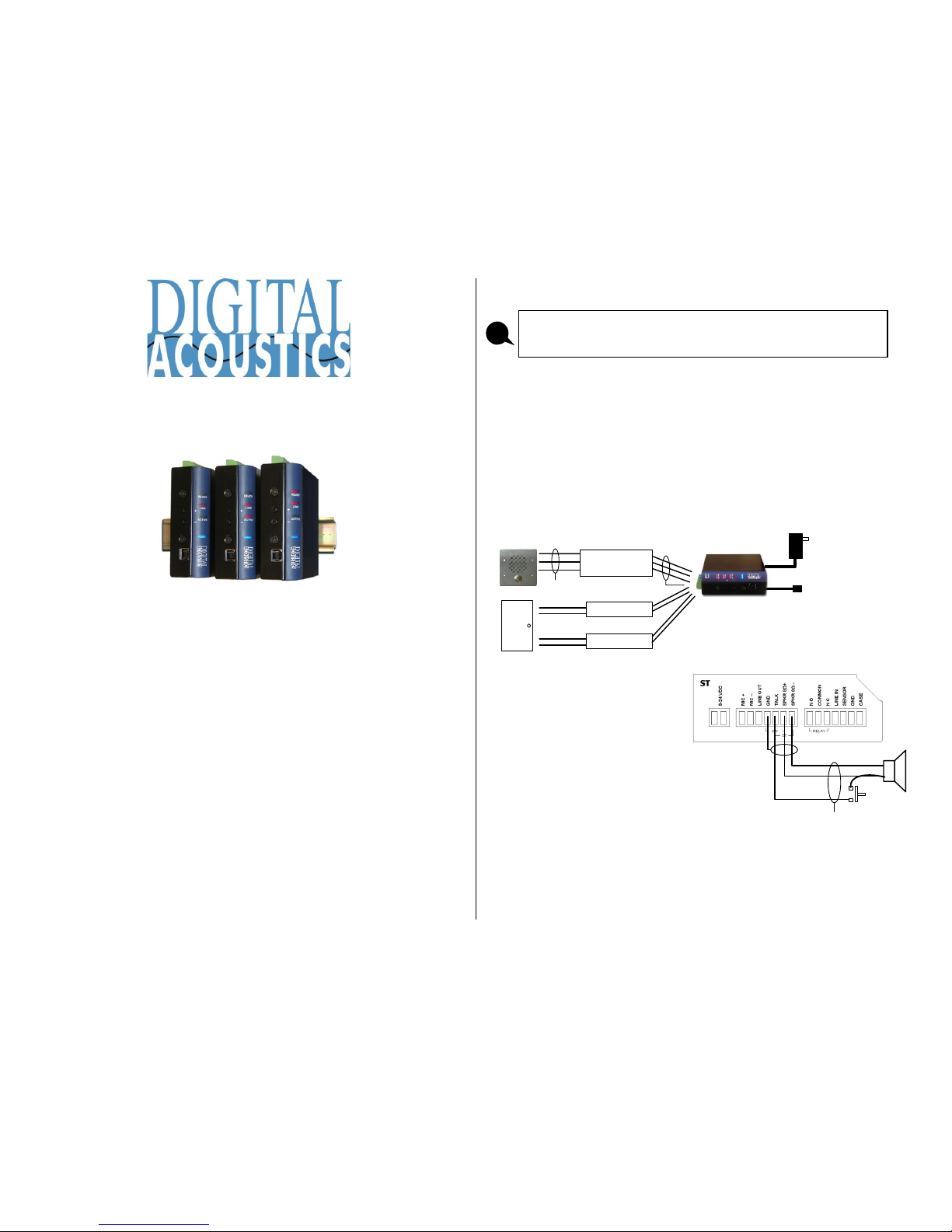
PNL-CISx Single Transducer Call Station Installation
Relay Output (Optional)
Cat-5/6 Cable to
Network Switch
PoE / 9VDC - 32VDC
2 Conductor Wire
18-20 AWG
Twisted Shielded
Sensor Input (Optional)
2 Conductor Wire
(No Connection)
• Set the internal ST-MIC switch
to the ST setting
• Connect SPKR 8Ω+ and SPKR
8Ω- (J2-6 and J2-7) to the
speaker terminals on the call
station (polarity independent)
• Connect TALK (J2-5) to one
contact on the call station’s
TALK button
• Jumper the remaining contact
on the call station’s TALK button
to one of the speaker terminals (this wire should be limited to 10ft or 3
meters)
• Connect GND (J2-4) to the shield of the shielded wire. Do not connect the
shield at the door station
Please refer to the IP7-ST/STx Reference Manual available on the Software
Installation CD for additional information on installation and setup
i
Talk Button
Talkback Speaker
No Connection
J1
J2 J3
Page 2
Page 2 of 4
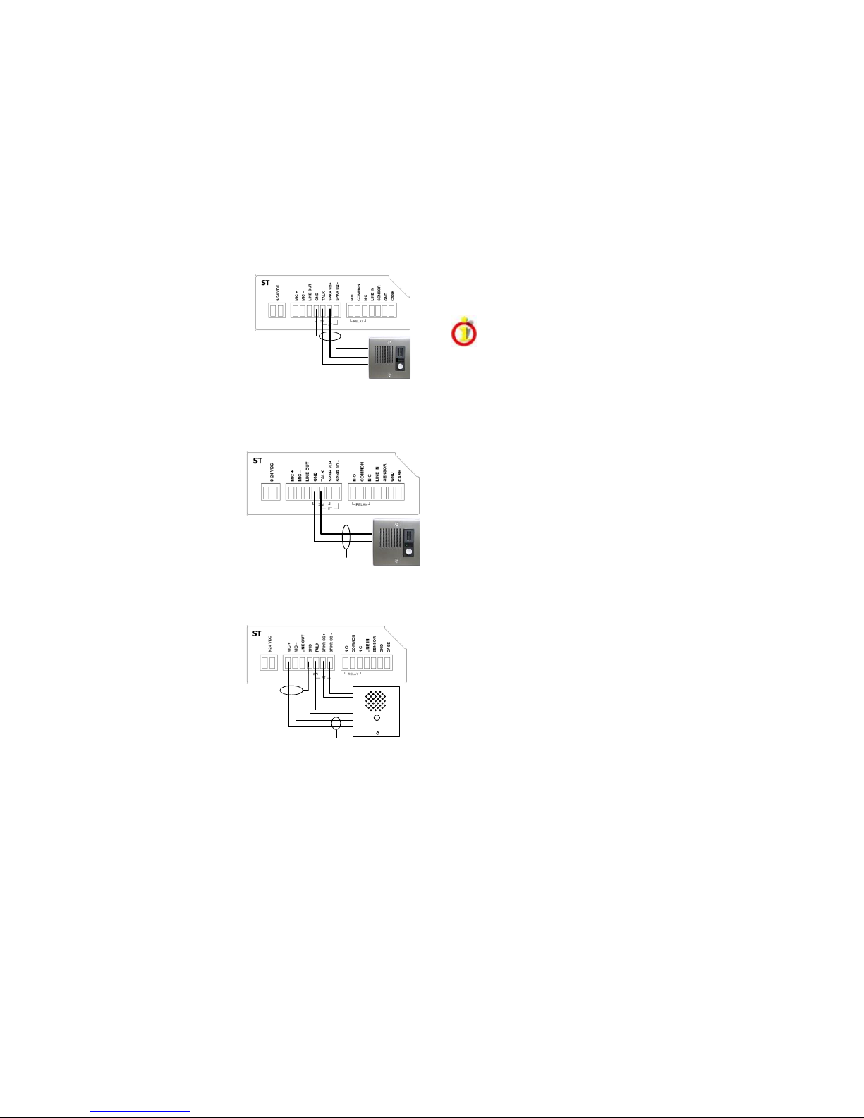
Aiphone™ LE / LS series 3-wire Call Station Installation
• Set the internal ST-MIC switch to the ST
setting
• Remove Aiphone shorting link between
E and - terminals
• Connect SPKR 8Ω+ and SPKR 8Ω- (J2-
6 and J2-7) to the “1” and “E” terminals
on the Aiphone call station
• Connect TALK (J2-5) to Aiphone “–“
(minus) terminal
• Connect GND (J2-4) to the shield of the shielded wire. Do not connect the
shield at the call station
Aiphone™ IE / IF series 2-wire Call Station Installation
• Set the internal ST-MIC switch to the
MIC setting
• Connect GND and TALK (J2-4, J2-5)
to Aiphone terminals 1 and 2 (polarity
independent)
• Connect GND (J2-4) to the shield of
the shielded wire. Do not connect the
shield at the door station
Call stations with a separate microphone, speaker and Call button
• Set the internal ST-MIC switch to the MIC setting
• Connect MIC+ and MIC- (J2-1, j2-2) to
the call stations microphone
• Connect GND (J2-4) to the shield of
the shielded wire. Do not connect the
shield at the call station
• Connect SPKR 8Ω+ and SPKR 8Ω-
(J2-6 and J2-7) to the call stations
speaker terminals
• Connect TALK (J2-5) to one contact
on the call station’s TALK button
• Connect the other contact on the call station’s TALK button to GND (J2-4)
or jumper it to one of the speaker terminals (this wire should be limited to
10ft or 3 meters)
Driving an Analog Paging Amplifier
The IP7-ST/STX has the capability to drive a balanced 600 Ohm input of an
analog amplifier using SPKR 8Ω+ and SPKR 8Ω- (J2-6 and J2-7). Set the
IP7’s volume level to 6 and adjust the amplifier’s volume control accordingly.
If the analog amplifier uses an unbalanced input, then the IP7’s Line
Out and GND (J2-3 and J2-4) must be used instead of SPKR 8Ω+
and SPKR 8Ω-. Failure to do so will damage the IP7 and void its
warranty.
Relay Options
• The integrated Relay uses COMMON (J3-2), along with NO - Normally
Open (J3-1) or NC - Normally Closed (J3-3). Use Admin Console to
configure the options
Sensor Options
• The integrated Sensor can be used to monitor the status of a door by
connecting Sensor (J3-5) and GND (J3-6) to a contact closure sense
switch. Use Admin Console to configure the options
Power Options
• Power over Ethernet (PoE - 802.3af compliant) - requires 7 watts from
Power Source Equipment (PSE)
• 9VDC - 32VDC external via J1-1 and J1-2 connectors or Aux Power
2.1mm barrel connector
• An external power supply, if detected, overrides PoE power
Network Installation
• Connect an RJ-45 cable between the Ethernet 10/100 connector and a
10/100 network switch
• On the IP7-STx, after the Ethernet 10/100 is connected, another IP device
can be connected to Port 2 10/100 jack
Mounting Instructions
The IP7 series is design to be mounted on standard 35mm DIN rail or
surface mounted using the surface mounting plate.
• DIN Rail Clip – Tilt top of unit (J1, J2, J3 connectors facing up with Volume
buttons facing forward) back towards the DIN Rail until the IP7 DIN clip
catches the top of the rail. Press in at the bottom of the IP7 to snap into
place
• Surface Mount Plate – Snap the surface mount plate in half and secure it
to the back of the unit using the provided screws so that the mounting
holes extend past the edges of the case
Aiphone LE, LS series
J1
J2 J3
Aiphone IE, IF series
J1
J2 J3
No Connection
J1
J2 J3
Call
Page 3
Page 3 of 4
TalkMaster™ Software
TalkMaster™ Server Software is a suite of Windows® based applications
used to configure and manage Digital Acoustics IP7™ and ii3™ Intercoms
and Paging endpoints. Applications included with the TalkMaster Server are
the Admin Console for configuration of the Server and IP Endpoints and the
Operator Console for managing 2-way Intercom calls and 1-way Paging
announcements.
• Install the TalkMaster software using the Software Installation CD
• Refer to the previous section to power up and connect the IP7 series
device to the network.
• Record the unique ID# from the bottom label of the IP Endpoint and note
the location where it will be installed
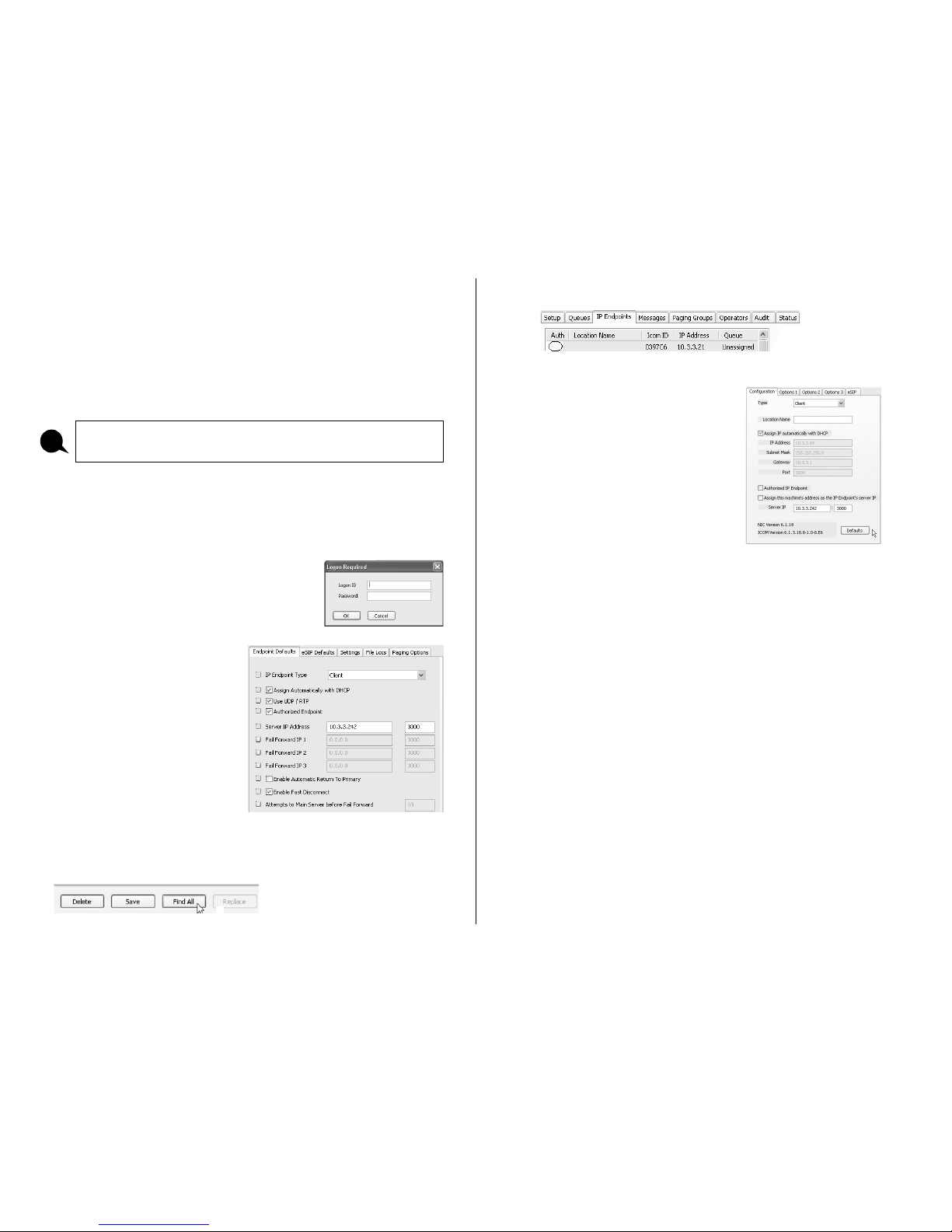
• Start the Admin Console and logon with an
Operator ID of admin and the default password
of admin
• Click the Settings → Endpoint
Defaults tab and make any
changes required for your
installation. For instance, if you
want to assign static IP
Addresses, uncheck the Assign
Automatically with DHCP
checkbox
• Click the IP Endpoints tab and press the FIND ALL button in the lower
right hand corner of the screen. Newly discovered IP Endpoints appear in
the list
• Click on the IP Endpoint to be configured (the “Icom ID” column must
match to the Intercom’s previously recorded ID#)
• Click the Defaults button to fill in default
values from the Endpoint Defaults tab
• Enter a descriptive name into the
Location Name field
• Make any other desired changes, then
select the Options 1 tab
Optional configuration options include:
Options 1 tab
Relay Options
• Door Open - adds an ICON to the Operator Console so the Operator
can activate the Relay for an electronic door strike
• PTT - Activates the Relay when the ‘Talk’ switch (J2-5) is grounded
• Activate on Speaker and/or Mic - activates the Relay when either MIC
and/or Speaker is active
Sensor Options - Used in conjunction with Door Open Relay. Changes the
color of the ICON in the Operator Console when the door is open
• Active when Closed to Ground - when J3-5 is closed to ground
• Activate when Open to Ground - when J3-5 is open to ground
Please refer to the TalkMaster Admin Console Reference Manual on the
Software Installation CD for additional information and software setup options
i
Page 4
Page 4 of 4
Options 3 tab
IP Endpoints can be optionally assigned to Queues
• Assigned Queue – select the Queue that the IP7 has been assigned to
Change additional IP7 Configuration Options and click SAVE when changes
have been completed
Press the Update Now button and close the Admin Console
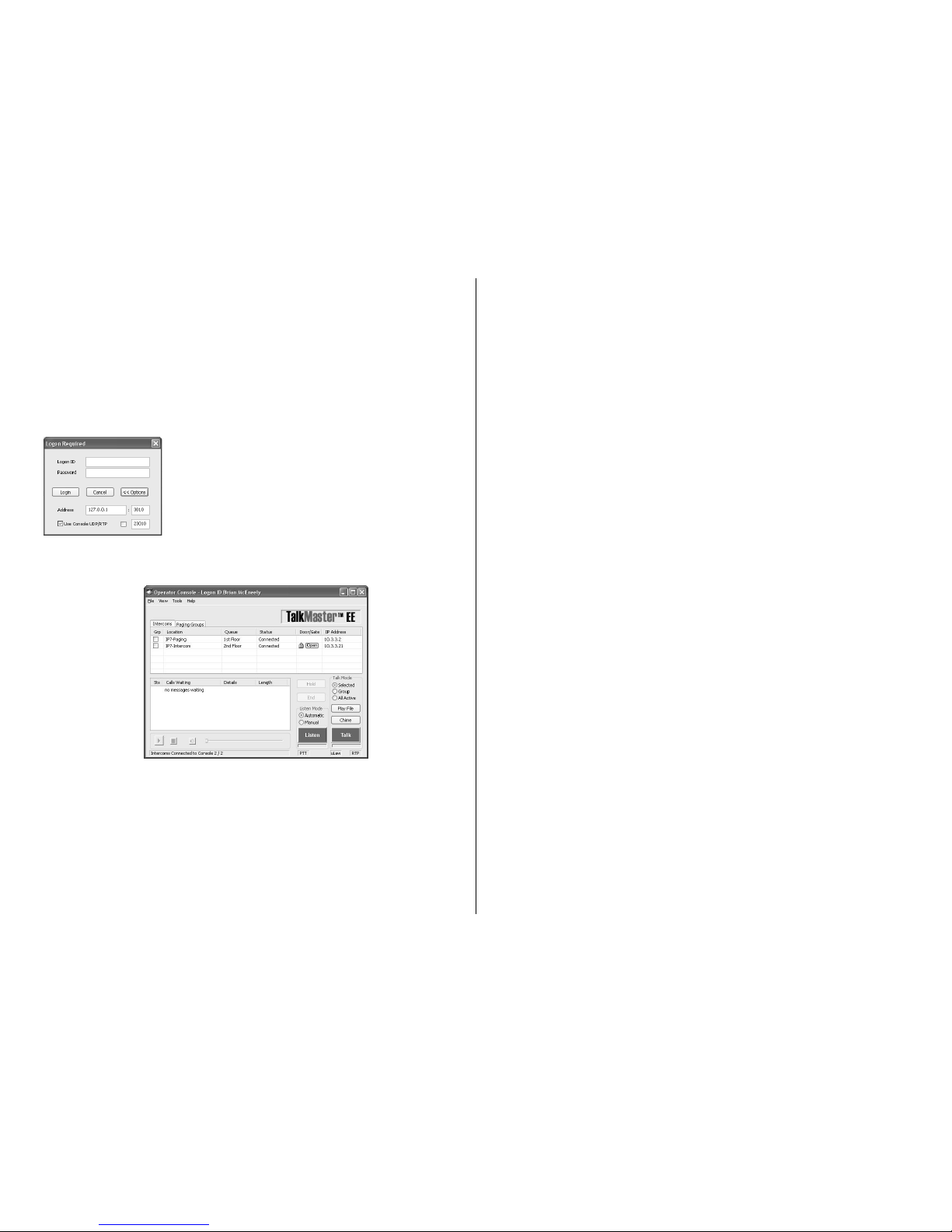
Start the Operator Console
• Logon with an assigned Operator ID and
Password or as the admin
• Specify the IP Address of the TalkMaster Server
(specify 127.0.0.1 if the Operator Console is
running on the TalkMaster Server PC)
• IP Endpoints will appear on the Intercoms tab or as part of the Paging
Groups tab of the Operator Console
• The PC’s microphone is used to send audio to an IP Endpoint
• The audio from an IP Endpoint can be heard on the PC’s speakers
Inbound Calls
• When the Talk button attached to the IP7 is pressed, Operator Console will
display the Incoming Call dialog and sound an audible alarm
• Click and hold the Talk button, or press and hold the Space Bar to speak
to the IP Endpoint
• Release the Talk button or Space Bar to automatically activate the Listen
button
• All incoming calls will be listed in the Calls Waiting list and remain “in
session” until removed from the Calls Waiting list by clicking the End
button, or pressing the Escape key
Outbound Calls
• To make an outbound call, select an IP Endpoint by clicking on it and press
the Talk or Listen button
• Click the Listen button or press the Escape Key to end the call
Open Door
• To open a door, select the Intercom, the click the Door Open Icon or
press the Enter key
IP7-ST/STX™
Getting Started Guide
Refer to the IP7-ST/STx Hardware Reference Manual for detailed
information on wiring, setup, configuring IP addresses and additional
software settings
IP7-ST-STX GettingStartedGuide.docu TalkMaster, IP7 and Digital Acoustics® are
trademarks of Digital Acoustics LLC. Other trademarks are the property
of their respective owners. All Rights Reserved ©2012 p/n 6620
www.digitalacoustics.com/support
 Loading...