

Page 1
™
IP7
IP Paging Amplifier
Reference Manual
-SS40
Page 2

This page left blank
Page 3

Table of Contents
Overview ........................................................................................1
Specifications .................................................................................2
IP7-SS40 Layout.............................................................................3
LED Indicators ................................................................................6
LEDs .............................................................................................. 6
LED Status Table ............................................................................. 6
LAN Connector LEDs......................................................................... 6
Connecting Power...........................................................................7
External Power ................................................................................ 7
USB Power...................................................................................... 7
Connecting a Speaker / Transformer..............................................7
SPKR 8Ω+ and SPKR 8Ω-.................................................................. 7
Speaker Configurations..................................................................... 7
25/70V Speaker(s) with optional 25/70V transformer............................ 8
8 Ohm Speaker(s) ........................................................................... 9
Connecting an I2C Bus..................................................................10
Mounting Instructions ..................................................................10
Din Rail Mounting............................................................................10
Surface Mounting............................................................................10
Setting Volume Levels ..................................................................11
Software Configuration.................................................................11
IP Address .....................................................................................11
Options .........................................................................................11
Environmental ..............................................................................12
Troubleshooting............................................................................13
Reset to Factory Defaults .................................................................13
Connecting 1/8” (3.5mm) Audio Plug to the Pluggable connectors..........13
Reducing electrical noise in audio ......................................................13
Viewing tech support info via the USB port .........................................13
Low Level Flashing Utility .................................................................14
Contacting Technical Support .......................................................14
Email support:................................................................................14
Telephone Support:.........................................................................14
Regulatory Notices .......................................................................15
Index............................................................................................16
i
Page 4
Overview
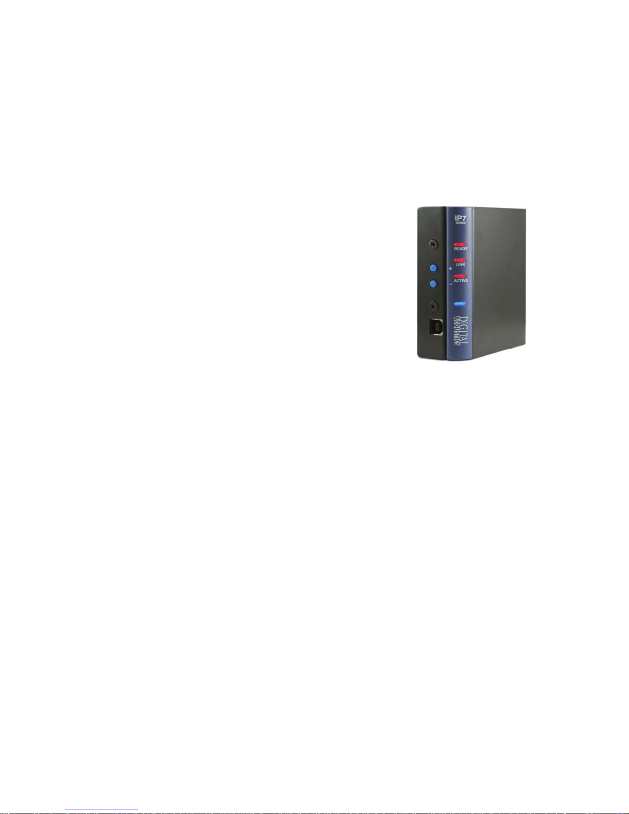
The Digital Acoustics IP7-SS40 is an IP (Internet Protocol) amplifier
that provide up to 40 watts of audio output. The SS40 is capable of
driving one or more speakers attached to a 25/70V audio distribution
line or an 8 ohm speaker.
Standard features include:
Drive one or more speakers for paging
applications
High quality 40 watt audio power with short
circuit protection.
Highly scalable and seamless expansion
DIN rail or surface mount
Fixed or DHCP compliant IP assignment
Field upgradeable OS using internal Flash
memory
Flexible User Access for delivering paging through VoIP/SIP 2.0
or TalkMaster ™ software
The IP7-SS40 must be configured using the TalkMaster software
before being used. Please consult the configuration section of the
software manual for details.
1
Page 5
Specifications
Items Specification
Hardware Protocols TCP, UDP, SIP, RTP, ICMP, IGMP Multicast
Network Interface 10/100 Ethernet (Auto detection, Auto MDIX)
Command protocols Proprietary (TalkMaster mode) or SIP 2.0
Audio Resolution G.711 (8-bit PCM and 16-bit uLaw)
Audio Sample Rate 8 kHz (Voice mode) 22kHz (Background Music)
Audio Frequency 90-4kHz (Voice band) , 90-11khz (Background Music)
Internal Amplifier 40 watts @ 8 Ohms @ 10% THD
Humidity 10~90%
Power 24 to 25 VDC @ 60 watts nominal
Size
3.85. x 3.59 x 1.37 in
98 mm x 91mm x 35mm
2
Page 6
3
5
IP7-SS40 Layout
1
2
4
6
7
J1
J2
3
Page 7
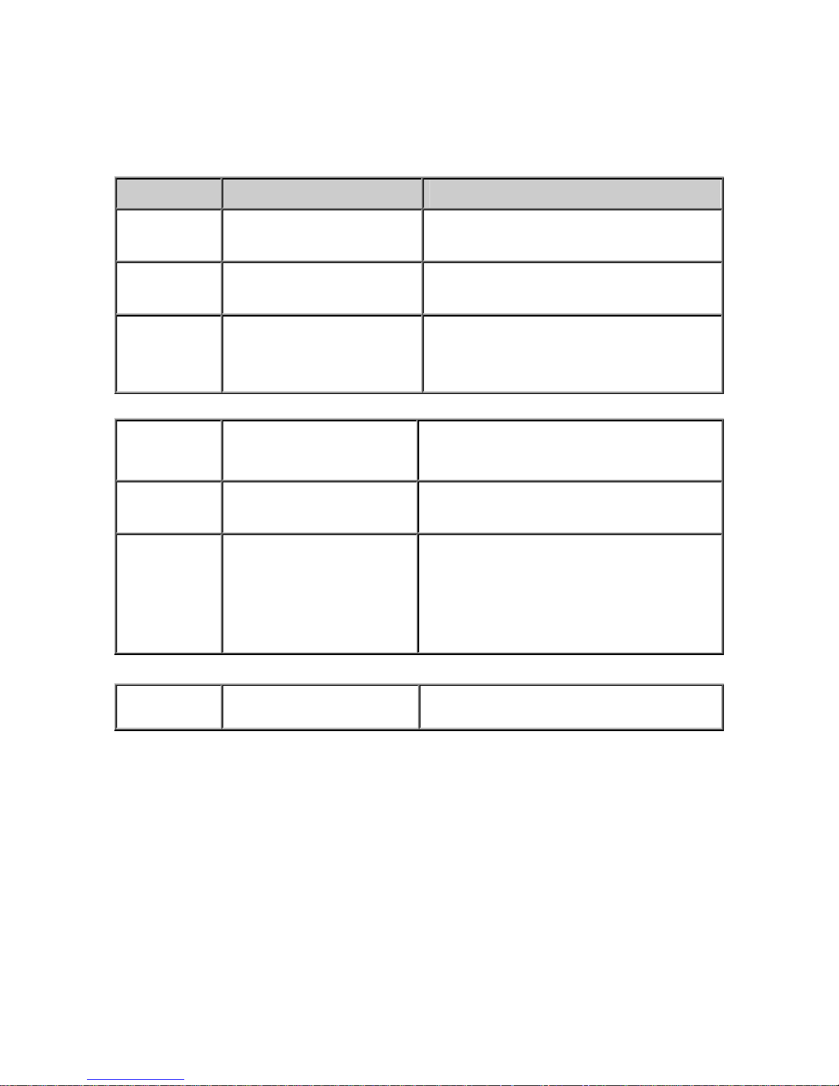
Connections and Controls
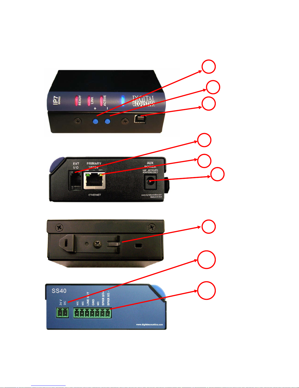
Refer to the preceding pictures.
Connector Connector / Control Notes
1 + Button Volume up button
2 - Button Volume down button
3 USB-B Provides for low level firmware flashing
as well as viewing technical support
information. Will also power the unit for
diagnostic purposes.
4 Ext I/O
5 Ethernet 10/100 10/100 Ethernet network interface.
6 Aux Power
7 DIN Rail Mounting Clip Allows unit to be snapped on to standard
I2C expansion bus interface that can be
used for custom applications. Requires
custom firmware from Digital Acoustics
Supports auto negotiation and auto-MDIX
2.1mm power connector with center tip
positive. 24V DC / CENTER POSITIVE
Warning: Connecting power to both the
2.1mm Power jack and the J1-1 and J1-2
power connectors at the same time will
damage the unit
35mm DIN Rail stock
4
Page 8
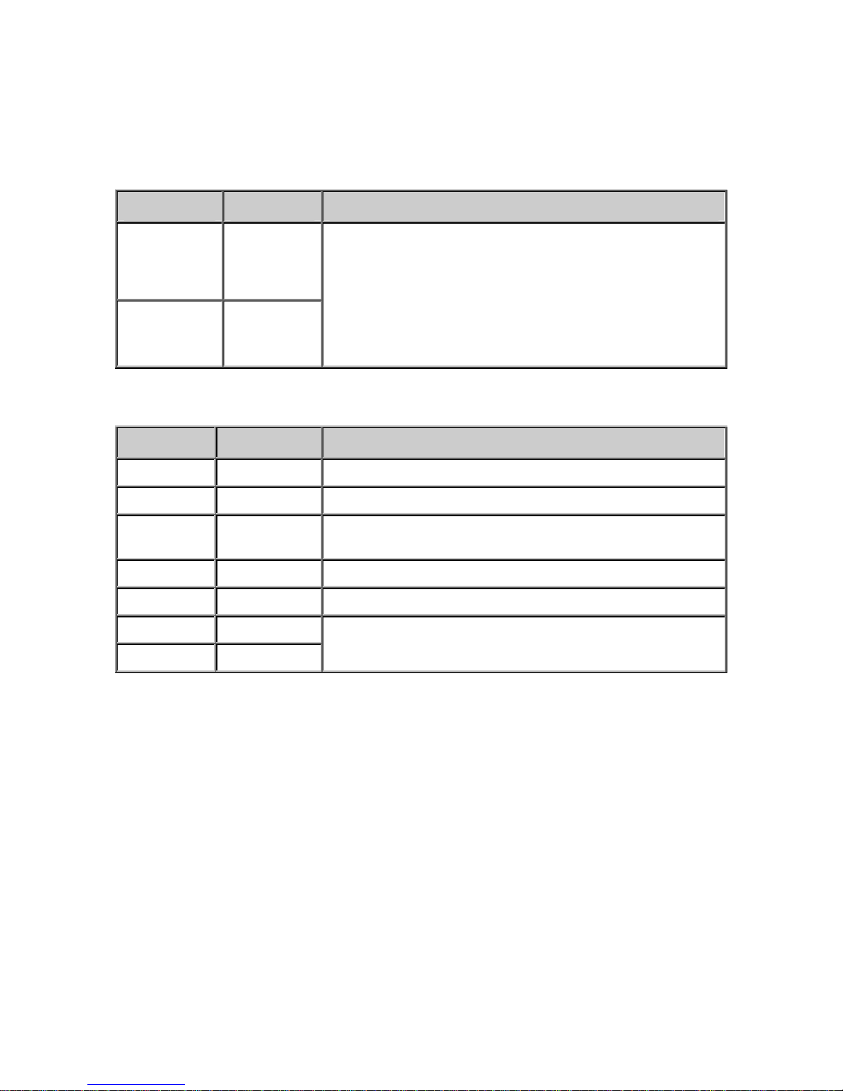
There are two sets of pluggable DIN connectors (3.81mm centers) on
the SS40:
SS40 J1 Connector
Connector Signal Notes
Note: The SS40 requires at least 60 watts of DC
power at 24 Volts to operate at maximum audio
power.
Warning: Connecting power to both the 2.1mm power
jack and the J1-1 and J1-2 power connectors at the
same time will damage the unit
J1-1
J1-2
Power +
24V DC
Power –
GND
SS40 J2 Connector
Connector Signal Notes
J2-1 nc No Connection
J2-2 nc No Connection
J2-3 Line Out
J2-4 GND System Ground
J2-5 nc No Connection
J2-6
SPKR 8Ω+
-10db with a 10k termination. Suitable for driving
powered multimedia speakers. Reference to J2-4
Floated* differential audio power amplifier output.
J2-7
SPKR 8Ω-
(*Do not apply either pin to ground)
5
Page 9
LED Indicators
LEDs
There are four LEDs present on the curved bezel on the front of the
product.
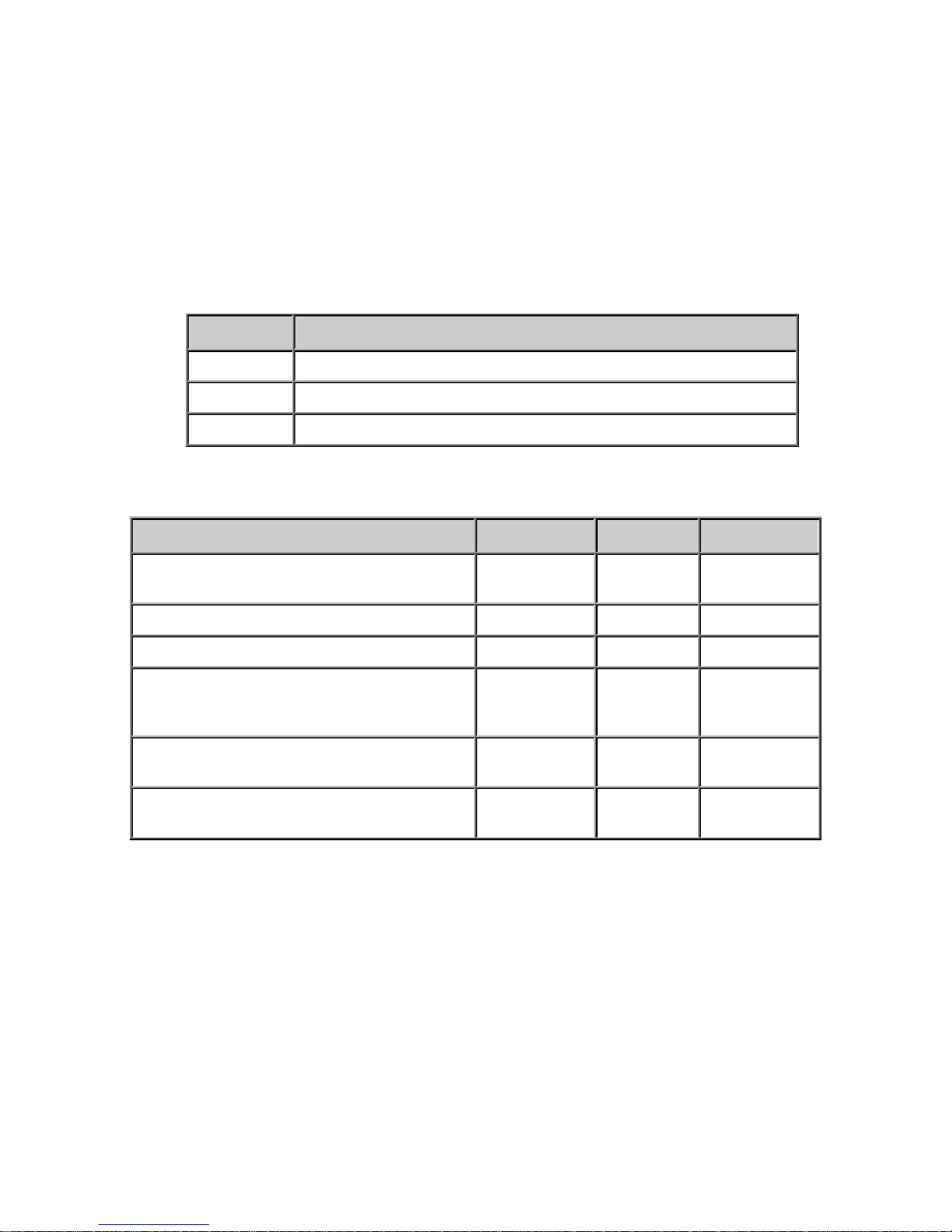
The blue LED indicates that the IP7-SS40 has powered up.
The three red LEDs indicate status of the unit.
LED Description
Ready Indicates whether the unit has connected to a Server
Link Indicates whether the unit has a valid network Connection
Active Indicates when audio is being received
LED Status Table
Description Ready Link Activity
Normal operational mode. Unit can
communicate with its Server
Playing Audio On On Flashing
Playing Broadcast Audio Fast Flash On Flashing
Attempting to connect to make a
connection or unit has not been
configured
LAN connection is inactive. The RJ45 may
be unplugged
Unit has been detected by the
Talkmaster Configuration Tool
On On Off
Flashing On
Flashing Off
Fast Flash On
LAN Connector LEDs
On the Ethernet 10/100 RJ-45 connector:
The Green LED tracks to the Ready LED
The Yellow LED tracks to the Link LED
Connecting to an Ethernet Network
The Ethernet 10/100 connector allows the unit to be attached to a
10/100 network.
6
Page 10

Plug a Cat5 cable into the RJ-45 connector labeled Ethernet
10/100 and connect the other end to a 10/100 switch.
The Ethernet 10/100 connector supports auto “MDIX” and can
be plugged directly into a PC for diagnostic purposes.
Connecting Power
The IP7-SS40 requires a 24VDC power supply rated at 60 watts.
External Power
The 2.1mm Power Jack (center tip positive) accepts 24 VDC
The J1-1 (+) and J1-2 (-) connector accepts 24 VDC
DO NOT supply power to both the 2.1mm Power Jack and the
J1-1 and J1-2 connectors
USB Power
The USB connector can be used to power up the unit for diagnostics or
low level firmware flashing. Plug a USB cable from a PC into the USB-B
connector. The unit will power up, but will not be able to be used for
audio operations.
Connecting a Speaker / Transformer
SPKR 8Ω+ and SPKR 8Ω-
The Speaker connectors are designed to drive an 8 Ohm load.
Connect J2-6 and J2-7 to the 8 Ohm side of an audio
transformer (polarity independent) or to the terminals or an 8
Ohm speaker
Please Note: Loads from 4 ohms to 12 ohms are supported,
however maximum power is transferred at 8 ohms
Speaker Configurations
The IP7-SS40 is designed to drive speakers attached to a 25/70V
distribution line (requires optional 25/70V Transformer) or an 8 Ohm
speaker. One or more speakers can be driven by a single IP7-SS40.
7
Page 11
25/70V Speaker(s) with optional 25/70V transformer
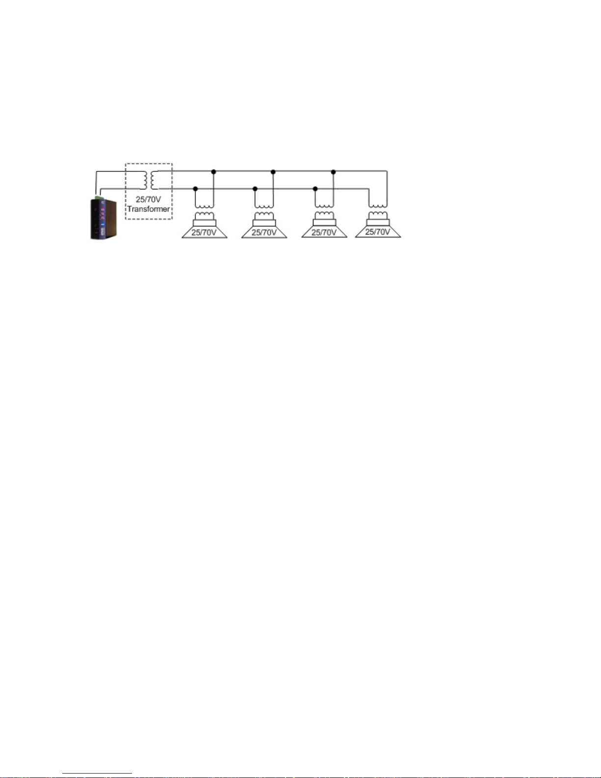
The SS40 can drive one or more 25/70V Speakers or Horns when
equipped with an optional 25/70V transformer. This is the
recommended installation method when driving multiple speakers.
Please note the following guidelines:
Each speaker must have its own 25/70V transformer
Do not mix Speakers tapped for 25V with a 70V distribution line
or speakers tapped for 70V with a 25V distribution line
All speakers must be wired in parallel.
Speakers should be installed within 3000 feet (900 meters) of
the SS40 using 14 gauge wire
The total wattage available from the SS40 must be reduced by
30% to account for transformer and line loss
The total wattage of the selected speaker taps cannot exceed the
wattage available from the IP7
Maintain the same wiring polarity between speakers
To use the optional transformer:
Mount the transformer next to the IP Amplifier
Connect the J2-6 (SPKR 8Ω+) and J2-7 (SPKR 8Ω-) from the IP
Amplifier to the 8 Ohm side of the transformer
Connect the 40 watt taps from the other side of the transformer
to the wires leading to the speaker(s)
Refer to the instructions included with the transformer for
additional information
25/70 volt systems should be installed within 3000 feet (900
meters) of the SS40 using 12-18 AWG depending on the length
of the wiring run
8
Page 12
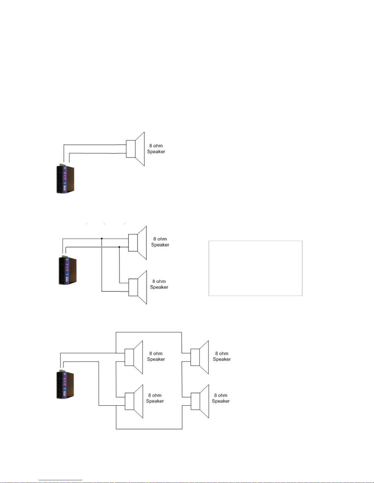
8 Ohm Speaker(s)
The following configurations are supported for driving 8 Ohm speakers.
If you plan on driving more than one speaker, consider using 25/70V
Speaker(s) with optional 25/70V transformer as described in the
previous section. The maximum distance between the IP7 and the
farthest speaker should not exceed 200 feet (60 meters)
A single 8 Ohm speaker
Two 8 Ohm speakers must be wired in parallel (total 4 ohm load).
Note:
Loads from 4 ohms to 12
ohms are supported by the
SS40, however maximum
power is transferred at 8
ohms.
Four 8 Ohm speakers must be wired in series-parallel
9
Page 13
Connecting Line Out
The Line Out connector is designed to drive a 600 Ohm unbalanced
load at -10db. This is capable of driving a powered multimedia
speaker
Connect J2-3 to the + side of the output source
Connect J2-4 to the - side of the output source
Cable length should not exceed 6ft (2 meters)
Use 22 AWG shielded/stranded cable
Connecting an I2C Bus
The IP7-SS40 can support an optional I2C bus via the RJ-10 connecter.
Buttons, relays and LEDs can be added to the I2C bus, BUT REQUIRE
CUSTOM FIRMWARE AND SOFTWARE. Please contact Digital Acoustics
for additional information.
Mounting Instructions
The IP7-SS40 can be installed on a DIN Rail or surface mounted.
Din Rail Mounting
To DIN rail mount:
Cut a piece of 35mm DIN rail (not supplied) to the desired length
and secure it to the wall
Place the IP7-SS40 onto the DIN rail by tilting the top of the unit
(J1, J2, J3 connectors facing up with Volume buttons and USB-B
connector facing forward) back towards the DIN Rail until the
IP7-SS40s DIN clip catches the top of the rail
Press in at the bottom of the IP7-SS40 to snap it in place
Surface Mounting
To surface mount:
Attach the detachable surface mount plate
to the back of the unit using the provided
screws. The two mounting holes of the
surface mount plate should be above the J1,
J2, and J3 connectors
Attach two (2) #8 pan head screws 2 inches
(52 mm) apart and screw in to within ¼”
Place the mounting holes of the IP7-SS40 over the #8 screws
10
Page 14

Attach one (1) #8 screw to the remaining hole at the bottom of
the mounting plate
Setting Volume Levels
The IP7-SS40 supports seven volume levels for an attached speaker.
Press the “+” or “-“ Button one time to increase or decrease the
speaker volume
If no audio is playing, a high frequency beep is heard when the
volume “+” is pressed and a low frequency beep is heard when
the volume “-” is pressed
Pressing the “-” or “+“ button seven times sets the unit at its
lowest or highest setting.
Refer to the software manuals for setting the volume via
software.
Software Configuration
IP Address
Refer to the software manuals for instructions on setting the IP
address information for the IP7-SS40
Options
Refer to the software manuals for instructions on setting the “Remote
Listen Disable” option in the IP7-SS40:
11
Page 15
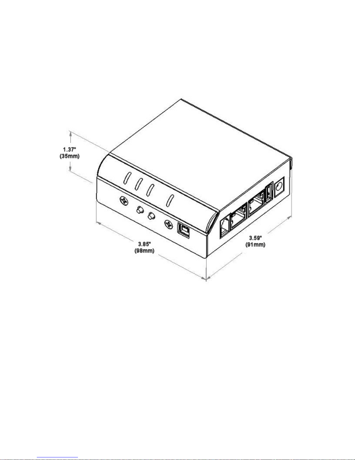
Physical Dimensions
The IP7-SS40 dimensions are as follows:
Environmental
The IP7-SS40 is designed to operate indoors or in a weather proof box
that has a NEMA4 or IP66 rating.
12
Page 16

Troubleshooting
Always refer the LED Indicator table when troubleshooting the IP7SS40.
Reset to Factory Defaults
The IP Address information and all options can be reset to factory
defaults by the following procedure:
Unplug the Power
Press and hold the “Vol +” and “Vol -“ buttons
Power the unit
Wait till the unit plays a 3 tone beep (about 5 seconds)
Release the “Vol +” and “Vol -“ buttons
Refer to the software manuals for instructions on setting the IP
address information
Connecting 1/8” (3.5mm) Audio Plug to the Pluggable connectors
To connect Line Out to the pluggable connectors via a 1/8” audio
connector, the audio plug should be wired as follows:
The Tip should be wired to J2-3 (Line Out)
The Sleeve should be wired J2-4 (GND)
On stereo plugs, the Ring should not be connected to the IP7
Reducing electrical noise in audio
Improper wiring can cause noisy audio when transmitting microphone
audio from the SS40. To minimize the possibility of this:
Locate the unit at least one meter away from transformers,
stepper motors or other noise producing equipment
Do not run audio cable in the same conduit with AC power
Attached J3-7 to an earth ground
Viewing tech support info via the USB port
If requested by Digital Acoustics Support, a USB cable can be attached
to the IP7-SS40 to capture additional information.
Attach a USB cable to the USB-B connector on the unit.
Attach the other end of the cable to a PC running Windows®.
If an “Install Hardware” prompt is displayed, insert the TM CD
that came with the product and install the USB Virtual Com port.
13
Page 17

Open the Windows Device Manager to determine the virtual
Serial port that has been assigned
Open the Windows® Hyperterm program (or similar terminal
emulation program) and set the properties to select the new
Serial port with settings of 115kbs, 8,N,1, no flow control and
ANSI Terminal
Press the Enter key
Provide the requested info to Digital Acoustics Tech support
Low Level Flashing Utility
If a power is removed from the unit while the firmware is being
updated from the network, the unit may require a low level flash.
Install the Low Level Flashing Utility from Technical Support
Remove the four screws (two on the front and two on the back)
Open the case by pulling up on the side opposite the Volume
buttons till the top pops off
Connect the USB cable (this will power the unit up)
Position the unit with the Vol “+” and Vol “-“ buttons facing you
Bend a paper clip or piece of wire and insert into the two holes
to the right of the Vol “+” and Vol “-“ buttons
Power cycle the unit by removing and reinserting the USB cable
Run the Low Level Flashing Utility and specify the file name of
the firmware
Repower the unit
Contacting Technical Support
Information online at www.digitalacoustics.com
Email support:
Telephone Support:
+1 (224) 544-5711 Mon-Fri 8-6 (Central Time Zone)
14
Page 18

Regulatory Notices
Federal Communication Commission Class A Notice
This equipment has been tested and found to comply with the limits for a Class A
digital device, pursuant to Part 15 of the FCC Rules. These limits are designed to
provide reasonable protection against harmful interference when the equipment is
operated in a commercial environment. This equipment generates, uses, and can
radiate radio frequency energy and, if not installed and used in accordance with the
instruction manual, may cause harmful interference to radio communications.
Operation of this equipment in a residential area is likely to cause harmful
interference in which case the user will be required to correct the interference at his
own expense.
In compliance with FCC regulations, the following information is provided on the
device or devices covered in this document.
Product Name: IP7 Series
Model number: SS20,Sx8,STx
Company name: Digital Acoustics LLC
37 Sherwood Terrace
Lake Bluff, IL 60044
847-604-9246
IC Notice (Canada Only)
This Class A digital apparatus complies with Canadian ICES-003.
Cet appareil numérique de la classe A est conforme à la norme NMB-003 du Canada.
NOTE: Industry Canada regulations provide that changes or modifications not
expressly approved by Digital Acoustics, LLC could void your authority to operate this
equipment
CE Notice
Marking by the symbol indicates compliance of this equipment to the EMC
(Electromagnetic Compatibility) directive of the European Community. Such marking
is indicative that this equipment meets or exceeds at least an EN 55022:2006
Class A device
VCCI Compliance
Class A
AS/NZS CISPR22:2006 Compliance
Class A
CNS 13438 Compliance
Class A
15
Page 19

Index
- Button.......................... 4, 11
+ Button......................... 4, 11
Aux Power ........................... 4
DIN rail mount.....................10
DIN Rail Mounting Clip........... 4
Ethernet 10/100 ................... 4
Ext I/O ................................ 4
External Power ..................... 7
IP Configuration...................11
LED..................................... 6
LED Status........................... 6
Line Out ...............................5
Line Out connector ............. 10
Options .............................. 11
Power ..................................5
Power - ................................5
SPKR 8Ω- .............................5
SPKR 8Ω+ ............................5
surface mount..................... 10
USB Power ...........................7
USB-B.................................. 4
Volume .............................. 11
16
Page 20
www.digitalacoustics.com
Digital Acoustics' product designs are packaged by leading
manufacturers around the world. Contact factory for
technical specification before product design and/or use.
Design and specification are subject to change without
notice.
Digital Acoustics®, IP7™, ii3™ and TalkMaster™ are
trademarks of Digital Acoustics, LLC. I2C is a registered
trademark of NXP Semiconductors, Inc. All other marks
used are properties of their respective owners.
Copyright 2007-2012, All Rights Reserved
IP7-SS40 Reference Manual.docu 2012-03-29-6
 Loading...