

Page 1
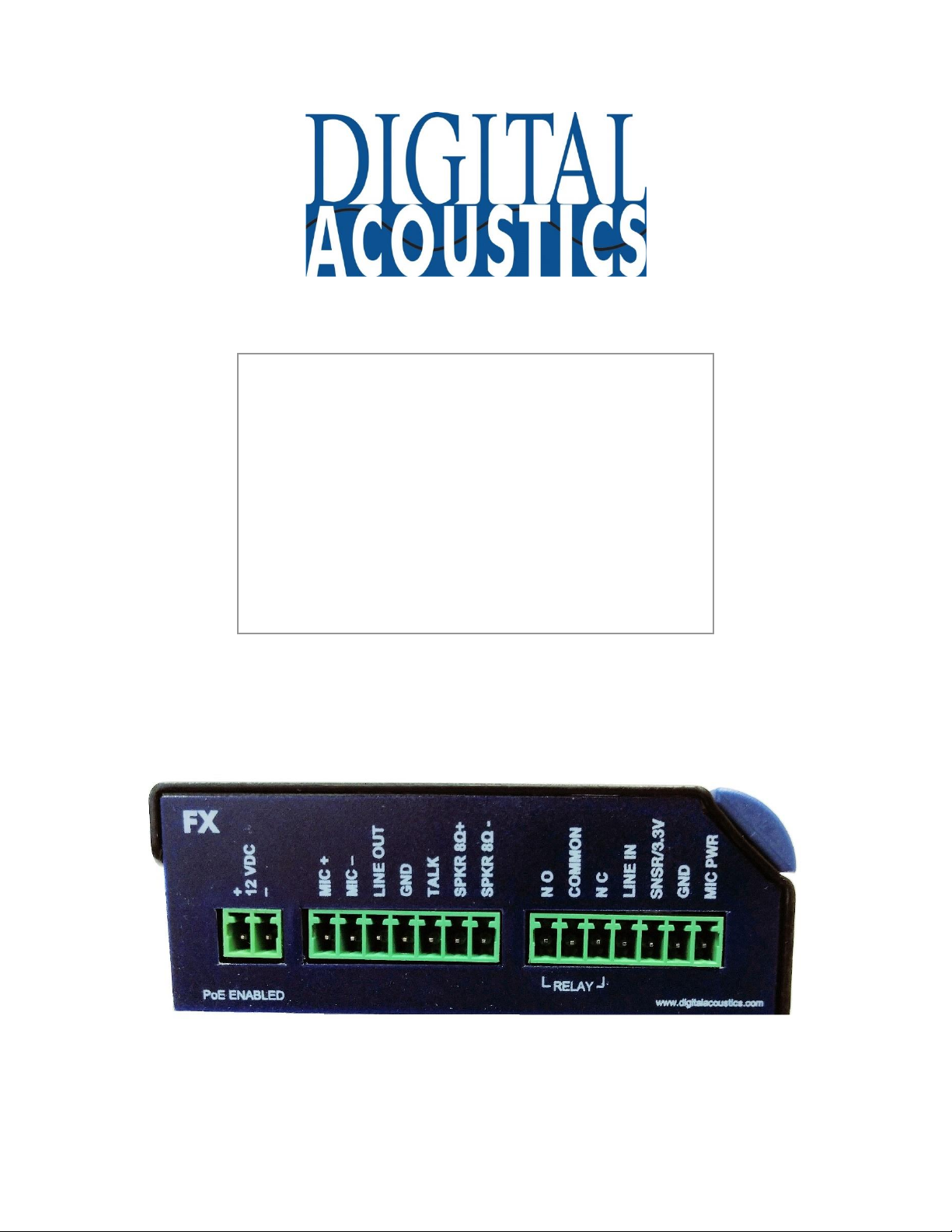
IP7™-FX
IP Intercom/Amplifier
Reference Manual
Page 2

This page left blank
Page 3

i
Table of Contents
Overview ................................................................................................................................................. 1
Specifications ........................................................................................................................................... 2
IP7-FX Layout ........................................................................................................................................... 3
LED Indicators .......................................................................................................................................... 6
Replacing an older Model IP7 .................................................................................................................. 7
Connecting Power .................................................................................................................................... 7
PoE ............................................................................................................................................................. 7
External Power ........................................................................................................................................... 8
USB Power ................................................................................................................................................. 8
Audio - Mic and Speaker .......................................................................................................................... 8
Understanding Full Duplex Audio .............................................................................................................. 8
Understanding Half Duplex Audio ............................................................................................................. 8
Understanding Paging Audio ..................................................................................................................... 8
Microphones ............................................................................................................................................ 9
Electret Microphone .................................................................................................................................. 9
Line Level Microphone............................................................................................................................... 9
TalkBack Speaker ....................................................................................................................................... 9
Speakers ................................................................................................................................................ 10
Single 8 Ohm Speaker .............................................................................................................................. 10
Amplified Speaker or Analog Amplifier ................................................................................................... 10
Multiple Speakers .................................................................................................................................... 10
Multiple Speakers using 25/70V transformers ........................................................................................ 10
Multiple 8 Ohm Speakers ........................................................................................................................ 12
Line Out ................................................................................................................................................. 13
Line In .................................................................................................................................................... 13
Talk (Call) Button ................................................................................................................................... 13
Dry Contact Relay .................................................................................................................................. 13
SNSR/3.3V.............................................................................................................................................. 14
Mounting Instructions ........................................................................................................................... 15
Din Rail Mounting .................................................................................................................................... 15
Surface Mounting .................................................................................................................................... 15
Setting Volume Levels ............................................................................................................................ 15
Configuration ......................................................................................................................................... 16
Page 4

ii
Physical Dimensions............................................................................................................................... 16
Environmental ....................................................................................................................................... 16
Troubleshooting ..................................................................................................................................... 17
Reset to Factory Defaults......................................................................................................................... 17
Connecting 1/8” (3.5mm) Audio Plug to the Pluggable connectors ........................................................ 17
Reducing electrical noise in audio ........................................................................................................... 17
Viewing tech support info via the USB port............................................................................................. 17
Low Level Flashing Utility ......................................................................................................................... 18
Technical Support .................................................................................................................................. 18
Regulatory Notices ................................................................................................................................. 19
Index ...................................................................................................................................................... 20
Page 5
Page 1
Overview
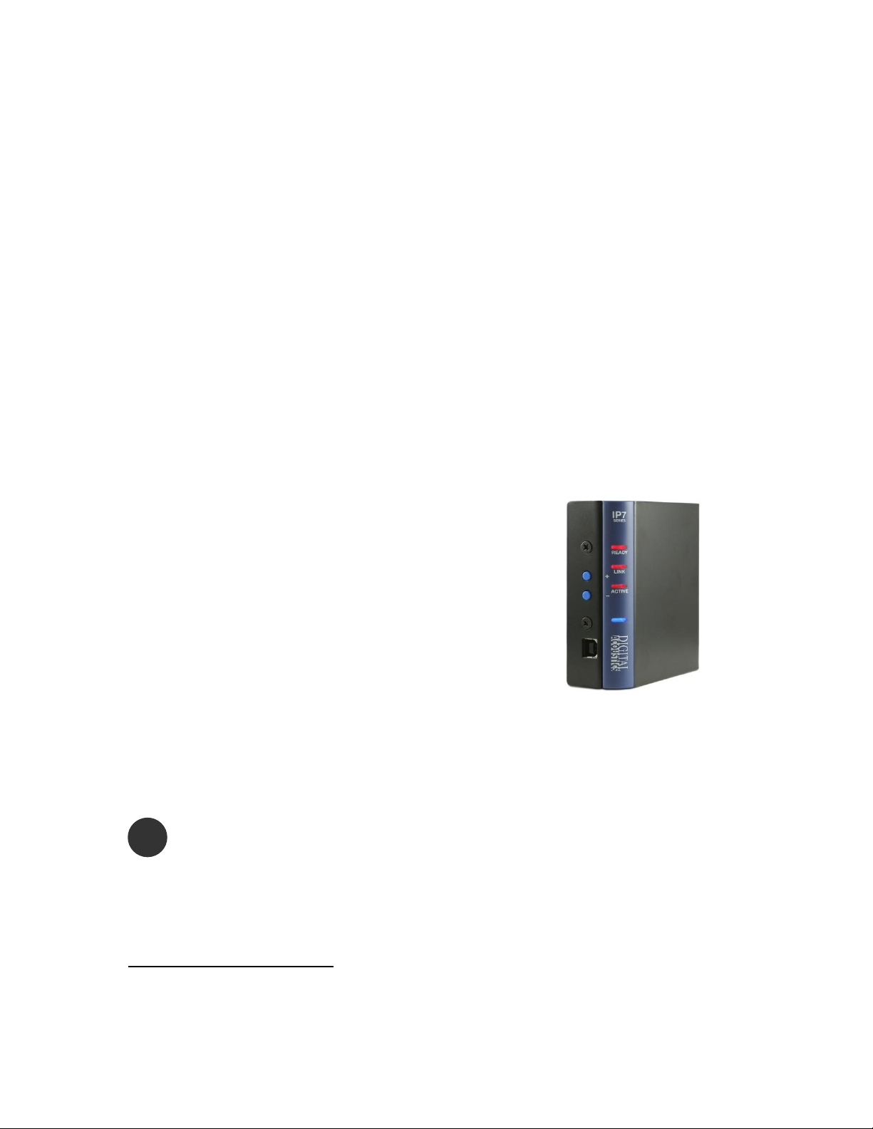
The Digital Acoustics IP7-FX is a versatile IP (Internet Protocol) 2-way audio
module with an integrated 8-watt amplifier, call button, relay, sensor and 2port network switch. It is designed to replace the older IP7-ST/STx1, IP7SS8, IP7-SE8 and the IP7-FD model IP audio modules and can support:
• Full duplex audio with echo cancellation
• Half duplex audio using a separate mic and speaker
• Half duplex audio using the speaker as both a speaker and microphone
• Paging only audio using one or more 8 Ohm speakers
• Paging only audio using an analog amplifier which is connected to
multiple speakers
With this flexible design the IP7-FX can be used in a variety of applications
where network-based audio is required.
Standard features of the IP7-FX include:
• Pluggable DIN connectors to facilitate wiring
connections
• Flexible analog audio device options
• Highly scalable, seamless expansion
• Mounting via rail or surface mount
• Fixed or DHCP compliant IP assignment
• Powered via external 12VDC or PoE (802.3af)
• Integrated 2-port switch
• Field upgradeable firmware
The IP7-FX must be configured using the TalkMaster software or
eSIP software before being used. Please consult the configuration
section of the software manual for details.
1
The IP7-FX does not support the Aiphone IE/IF Series two wire Door Station. The
IP7-STx is the only Digital Acoustics IP audio module that supports the IE/IF Series
!
Page 6

Page 2
Specifications
Items
Specification
Network Protocols
TCP, UDP, SIP, RTP, ICMP, IGMP Multicast
Network Interface
10/100 Ethernet (Auto detection, Auto MDIX)
Command protocols
Proprietary and Standards Based
Audio Resolution
G.711 (8-bit PCM and 16-bit uLaw)
Audio Sample Rate
8K (Voice band), 22K (Background Music)
Audio Frequency
90-4kHz (Voice band), 90-11khz (Background Music)
Internal Amplifier
8 watt @ 8 Ohms 1% THD
Humidity
10~90%
Power
External Power 12VDC @ 1.2 amps or 24VDC @ 2.5
amps.
PoE (802.3af) compliant (requires 15.4 watts from
PSE). External Power overrides PoE power
Size
3.85. x 3.59 x 1.37 in
98 mm x 91mm x 35mm
Page 7
Page 3
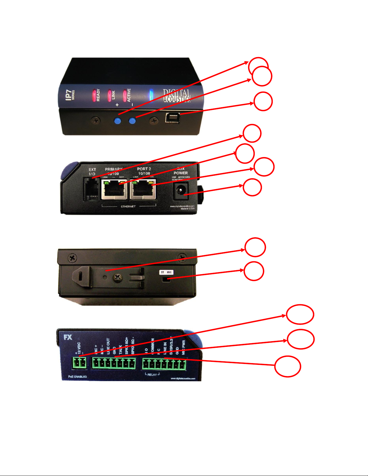
IP7-FX Layout
1
3
J1
8 5 9
J3
J2
2
Page 8
Page 4
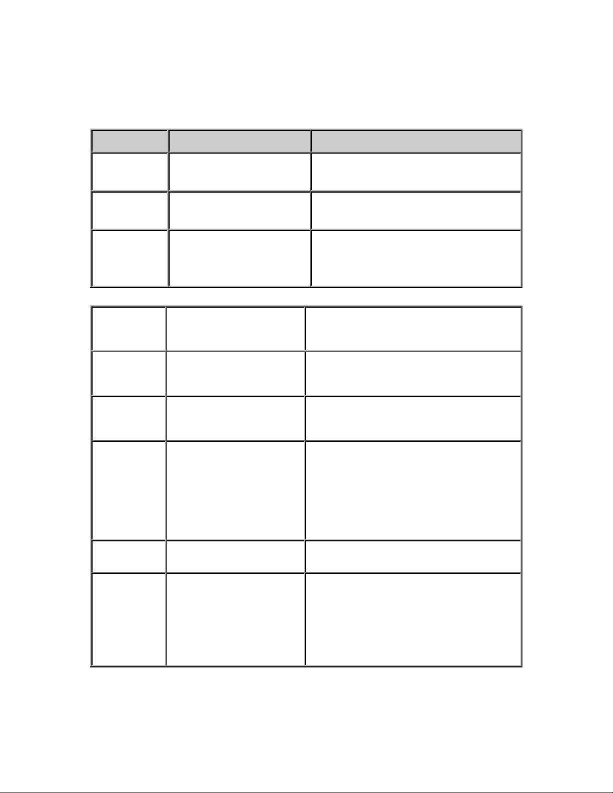
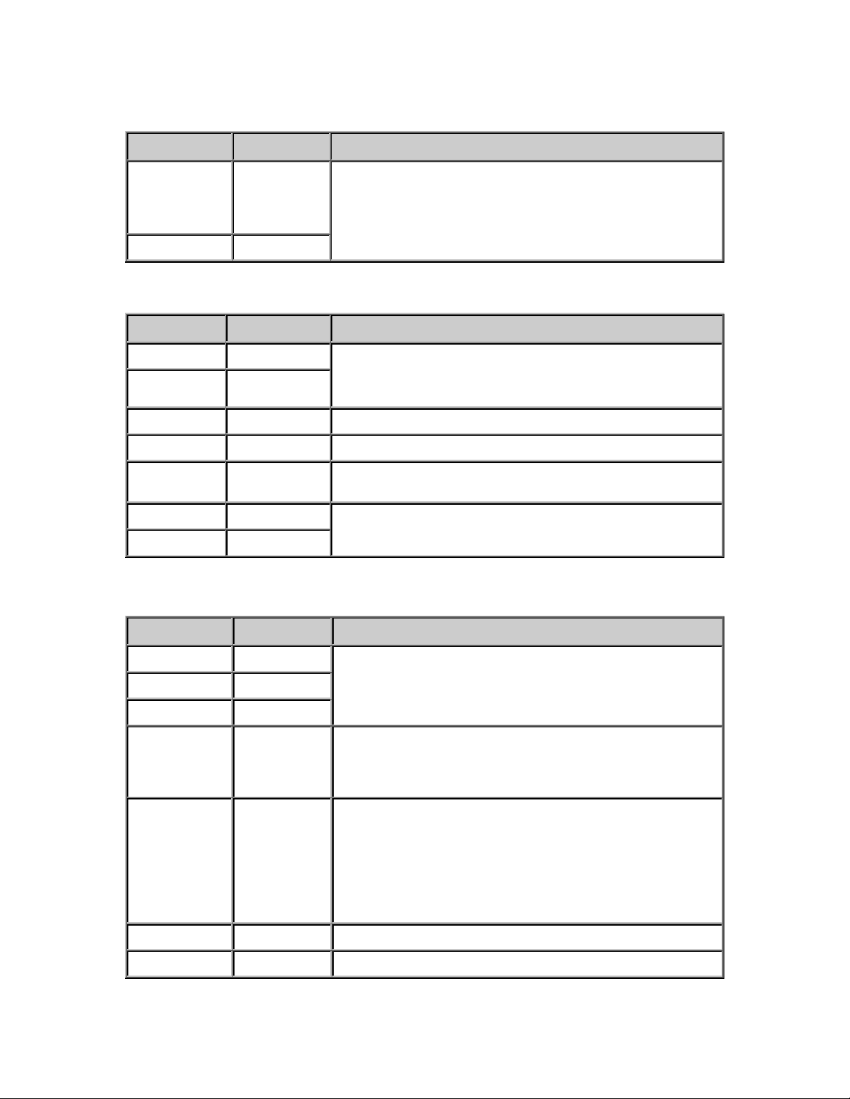
Connections and Controls
Refer to the preceding pictures.
Connector
Connector / Control
Notes
1
Volume Up
Volume up button +
2
Volume Down
Volume down button -
3
USB-B
Provides for low level firmware flashing
as well as viewing technical support
information. Will also power the unit
for diagnostic purposes.
4
Ext I/O
I2C expansion bus interface that can be
used for custom applications. Requires
custom firmware from Digital Acoustics
5
Ethernet 10/100
10/100 Ethernet network interface.
Supports auto negotiation and autoMDIX. PoE enabled
6
Port 2 10/100
Provides a 10/100 Ethernet network
connection for another device. Supports
auto negotiation and auto-MDIX
7
Aux Power
2.1mm power connector with center tip
positive. 12VDC @ 1.2 amps or 24VDC
at 2.5 amps. Overrides PoE power.
Warning: Connecting power to both
the 2.1mm Power jack and the J1-1 and
J1-2 power connectors at the same time
will damage the unit
8
DIN Rail Mounting Clip
Allows unit to be snapped on to
standard 35mm DIN Rail stock
9
ST MIC switch
The ST MIC switch is in the MIC
position by default. If using single
transducer mode (speaker used as both
a speaker and microphone) use a small
screwdriver to move the recessed
switch to the ST position (towards the
DIN clip).
Page 9
Page 5
J1 Connector
J2 Connector
J3 Connector
Connector
Signal
Notes
J1-1
Power +
12VDC at 15 watts or 24VDC at 2.5 watts. Overrides PoE
power.
Warning: Connecting power to both the 2.1mm power
jack and the J1-1 and J1-2 power connectors at the same
time will damage the unit
J1-2
Power -
Connector
Signal
Notes
J2-1
MIC +
Microphone Inputs. Pseudo differential (Actively Balanced
differential).
Also capable of accepting Line In signal
J2-2
MIC -
J2-3
Line Out
2VPP
J2-4
GND
System Ground. Same as J3-6
J2-5
TALK
Talk or Call button. Initiates a call to the configured
Server. Reference to J2-4
J2-6
SPKR 8Ω+
Floated differential output. Able to drive an 8 Ohm load @
8 watts or a 600 Ohm load
J2-7
SPKR 8Ω-
Connector
Signal
Notes
J3-1
NO
Isolated Dry Contact Relay output. Connect J3-2 and either
J3-1 for NO (Normally Open) or J3-3 for NC (Normally
Closed)
J3-2
COMMON
J3-3
NC
J3-4
LINE IN
Line In - Unbalanced. Reference to J3-6. Use J3-7 to
supply 12V to if needed to power a Line Level Microphone.
** NOTE: When configuring the device, make sure to
configure the Input Source from Microphone to Line In
J3-5
SNSR/3.3V
Sensor – Active when closed to ground (default) or
Active when open to ground based on software
configuration. Reference to J3-6.
Optionally provides 3.3V (current limited) to power an LED.
If powering an LED, make sure to configure SNSR/3.3V
from Activate when grounded to Activate when open
in the software configuration
J3-6
GND
System Ground. Same as J2-4
J3-7
MIC PWR
Provides 12VDC to power a Line Level Microphone
Page 10
Page 6
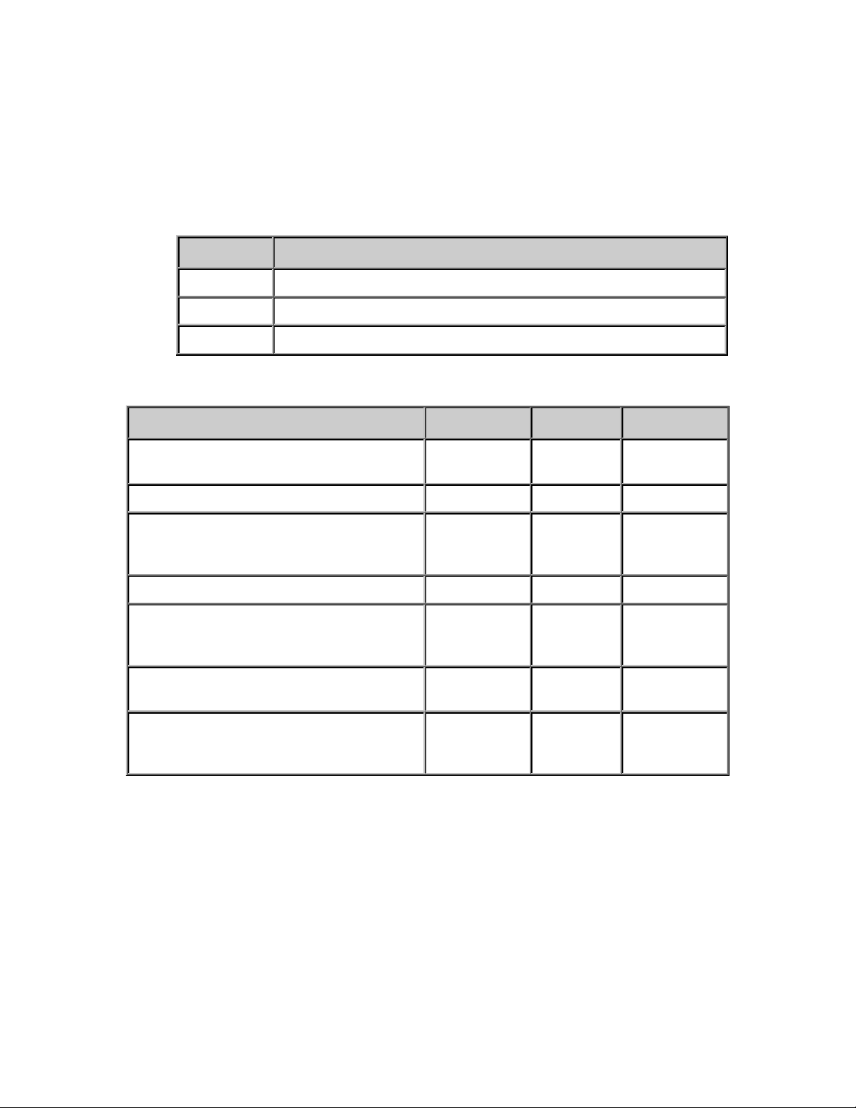
LED Indicators
Intercom LEDs
There are four LEDs present on the curved bezel on the front of the product.
• The blue LED indicates that the IP7-FX has powered up.
• The three red LEDs indicate status of the unit.
LED
Description
Ready
Indicates whether the unit has connected to a Server
Link
Indicates whether the unit has a valid network Connection
Active
Indicates whether audio is being transmitted or received
LED Status Table
Description
Ready
Link
Activity
Normal operational mode. Intercom can
communicate with its Server
On
On
Off
Playing Audio
On
On
Flashing
Playing Broadcast Audio
Fast Flash
20x per
second
On
Flashing
Sending Audio
On
On
On
Attempting to connect to make a
connection to a Server or unit has not
been configured
Flashing 4x
per second
On
LAN connection is inactive. The RJ45
may be unplugged
Flashing 4x
per second
Off
Device has reported its configuration on
a discovery request or connection. Fast
flash will stop after 20 seconds
Fast Flash
20x per
second
On
LAN Connector LEDs
On the Ethernet 10/100 RJ-45 connector:
• The Green LED tracks to the Ready LED
• The Yellow LED tracks to the Link LED
On the Port 2 10/100 RJ-45 connector
• The Green LED tracks to network transmit activity
• The Yellow LED tracks to network receive activity
Page 11

Page 7
Replacing an older Model IP7
If the IP7-FX is being used to replace an existing an existing IP7ST/STX, IP7-SS8/SE8 or an IP7-FD, please note the following:
• The J3-7 (Case) connector on older models was an extra
ground. If replacing an older model with an IP7-FX, any
wire connected to J3-7 should be moved to J3-6.
• If replacing an IP7-ST/STx, make sure the internal ST-MIC
switch (located on the DIN clip side) is set in the same
position on the IP7-FX
• If the older IP7’s J2-6 (SPKR 8Ω+) and J2-7 (SPKR 8Ω-) is
connected to an amplifier or amplified speaker, use the IP7FX’s J2-3 (Line Out) and J2-4 (GND) instead
• If replacing an IP7-SE8 / IP7-MSR-BRD with an IP7-FX, the
IP7-MSR-BRD can be eliminated by changing the IP7-FX’s
ST-MIC internal switch to the ST position
• The IP7-FX does not support the Aiphone IE/ IF series call
station. An IP7-ST/STx must be used
• Other than the exceptions noted above, the J1, J2, J3, and
network can be moved over to the IP7-FX
Connecting to an Ethernet Network
The Ethernet 10/100 connects to a 10/100 network switch port. Port 2
10/100 allows an additional IP device to be connected to the network
without the need for an additional network drop. The second port is not PoE
capable.
• Plug a Cat5 cable into the RJ-45 connector labeled Ethernet 10/100
and connect the other end to a 10/100 switch.
• To optionally connect a second IP device to the network, plug a Cat5
cable in the RJ-45 connector labeled Port 2 10/100
• The Ethernet 10/100 connector supports auto “MDIX” and can be
plugged directly into a PC for diagnostic purposes.
Connecting Power
The IP7-FX auto senses the power source and voltage. An external power
source will always override PoE power.
PoE
Plug a Cat5 cable from an 802.3af compatible switch or injector into the RJ45 connector labeled Ethernet 10/100. 15.4 watts will be requested from
PoE (802.3af compatible) Power Source Equipment (PSE).
Page 12

Page 8
External Power
• The 2.1mm Power Jack (center tip positive) and the J1-1(+) / J1-2(-)
connectors both accept 12VDC at 1.2 amps or 24VDC at 2.5 amps
(With 12VDC, the IP7-FX can supply up to 8 watts to the speaker.
With 24VDC, the IP7-FX can supply up to 25 watts to the speaker)
• DO NOT supply power to both the 2.1mm Power Jack and the J1-1
and J1-2 connectors
USB Power
The USB connector can be used to power up the unit for diagnostics or lowlevel firmware flashing. Plug a USB cable from a PC into the USB-B
connector. The unit will power up but will not be able to be used for audio
operations.
Audio - Mic and Speaker
Understanding Full Duplex Audio
The IP7-FX Full Duplex Operation is often referred to as Speakerphone or
Hands-Free mode. The technology to enable 2-way conversation without
acoustic feedback involves a process called Acoustics Echo Cancellation
(AEC). For AEC to be effective, the total system design needs to be
considered. This includes incorporating sophisticated DSP electronics and
optimizing the Speaker Frequencies and placement of the speaker and
microphone based on the maximum volume to be played on the speaker.
The Digital Acoustics IP7-FX series has highly advanced DSP electronics with
software that can optimize the endpoint based on the physical environment.
In full duplex echo cancellation mode, when the distance between the
microphone and speaker is small (under 24”), the speaker volume and
microphone sensitivity are limited to help prevent feedback. As the distance
between the two increases, the microphone sensitivity and speaker volume
can increase as there is less chance of feedback.
Understanding Half Duplex Audio
In half duplex audio mode, only the speaker or microphone is active at any
one time. In this mode, the speaker volume and microphone sensitivity can
both be maximized since there will not be any feedback.
Understanding Paging Audio
In paging mode, only the speaker will be active. The speaker volume can be
maximized since there will not be any feedback.
Simple ‘dialog’ choices in the configuration software offer several Audio
Profiles for different environments. Please refer to the Admin Console
Reference Guide for more information on selecting Audio Profiles.
Page 13

Page 9
Microphones
The IP7-FX can receive audio through a microphone and transmit it across
the network to be played or stored. There are several types of microphones
with different pickup patterns (omni directional, unidirectional, etc.). The
IP7-FX supports Electret and Line Level Mics as well as TalkBack Speakers.
Electret Microphone
An electret microphone (sometimes referred to as un-pre-amplified mic)
transmits “mic level” audio to the IP7-FX. To use an electret microphone:
• For best results and to minimize interference connect to the
microphone to the IP7-FX with 18-20 AWG shielded wire
• The Microphone wire must NOT be in the same jacket as the Speaker
wire!
• Connect the plus and minus leads to the IP7-FX’s J2-1 (Mic+) and J2-2
(Mic-) terminals
• Connect the shield to the IP7-FX J2-4 (GND), but do not connect the
shield on the microphone end
Some examples of electret microphones are the ETS ML1-x series and the
Louroe x-ML series.
Line Level Microphone
A line level mic (sometimes referred to as a powered or pre-amplified
mic) transmits “line level” audio to the IP8-FX. To use a line level mic:
• Connect the Black (or Audio) lead to the J3-4 (Line In) connector
• Connect the Shield (or Ground) to the J3-6 (GND) connector
• Connect the Red (or Power) lead to the J3-7 (MIC PWR) connector
Some examples of line level microphones are the ETS SM1 series and the
Louroe Verifact series.
TalkBack Speaker
Some 8 Ohm speakers work well as a microphone. To use a speaker as a
microphone:
• Connect the two speaker leads to the J2-1 (Mic+) and J2-2 (Mic-)
connectors. The connections are polarity independent
• Set the recessed ST MIC switch (connector 9 – next to the DIN clip) to
the ST position using a small screwdriver
Some call stations only have a single speaker that is used as both a speaker
and a microphone (also known as single transducer mode). The IP7-FX can
also support this configuration in half duplex operation.
Page 14

Page 10
• Connect the two speaker leads to the J2-6 (SPKR 8Ω+) and J2-72
(SPKR 8Ω-) connectors. The connections are polarity independent
• Set the recessed ST MIC switch (connector 9 – next to the DIN clip) to
the ST position using a small screwdriver. The ST MIC switch must be
in the MIC position for all other configurations!
• Make sure the IP7-FX software configuration is NOT configured for Full
Duplex
An example of a TalkBack Speaker is the Visiton FRS8-8.
Speakers
The IP7-FX receives audio from the network and plays it on its speaker. It
can drive one or more speakers, a self-amplified speaker or an analog
amplifier connected to one or more speakers. For best results and to
improve performance, connect the speaker or amplifier to the IP7-FX using
18 AWG wire.
Single 8 Ohm Speaker
To drive a single 8-Ohm speaker, connect the speaker leads to J2-6 (SPKR
8Ω+) and J2-7 (SPKR 8Ω-). The connections are polarity independent.
Amplified Speaker or Analog Amplifier
To drive an amplified speaker or analog amplifier connect the amplifier’s
Audio+ signal to J2-3 (Line Out) and the Ground to J2-4 (GND).
Do not connect the IP7-FX J2-6 and J2-7 connectors to an
unbalanced audio signal. This will cause permanent damage
and void the warranty!
Multiple Speakers
Multiple speakers are typically used if the IP7-FX will be used for
overhead paging. If more than one speaker is connected to an IP7-FX,
all speakers will sound when audio is sent to it.
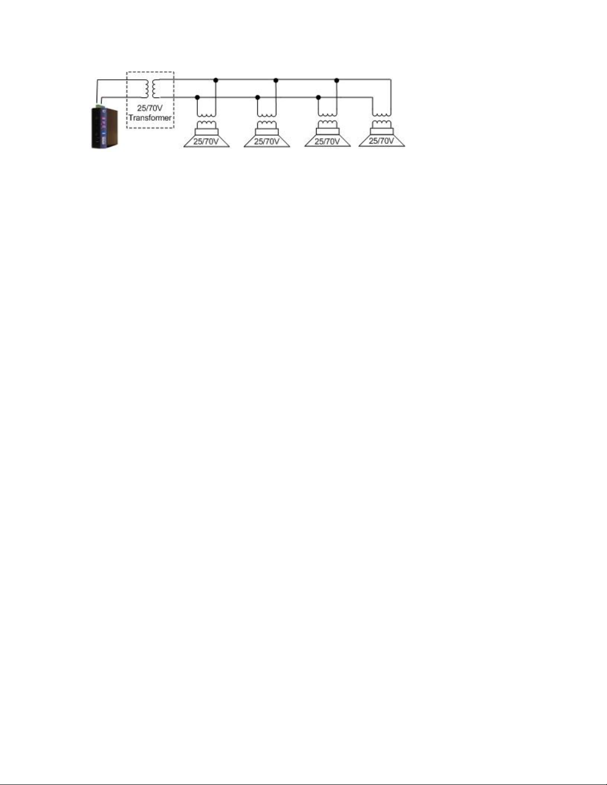
When driving multiple speakers, it is recommended that a 25/70V
distribution line be used. This requires the optional 25/70V
transformer (part# COMTR25/70-324J) for the IP7 and speakers with
25/70V transformers.
Multiple Speakers using 25/70V transformers
Due to transformer loss, the IP7-FX will only:
• Supply about five watts to the speaker output when using PoE or
12VDC.
• Supply about 30 watts to the speaker output when using 24VDC
Page 15
Page 11
Please note the following guidelines:
• Each speaker must have its own 25/70V transformer
• Do not mix Speakers tapped for 25V with a 70V distribution line
or speakers tapped for 70V with a 25V distribution line
• All speakers must be wired in parallel.
• Speakers should be installed within 500 feet (150 meters) of the
IP7-FX using 18-gauge wire. For longer runs, increase the wire
gauge
• Each speaker may be tapped differently
• The total wattage of the selected speaker taps cannot exceed the
five watts (12VDC or PoE) or thirty watts (24VDC) available from
the IP7
• Maintain the same wiring polarity between speakers
To use the optional transformer:
• Mount the transformer next to the IP Amplifier
• Connect the J2-6 (SPKR 8Ω+) and J2-7 (SPKR 8Ω-) (polarity
independent) from the IP Amplifier to the 8 Ohm side of the
transformer
• Connect the 10 watt tap and common from the other side of the
transformer to the wires leading to the speaker(s)
• Refer to the instructions included with the transformer for
additional information
Page 16
Page 12
Multiple 8 Ohm Speakers
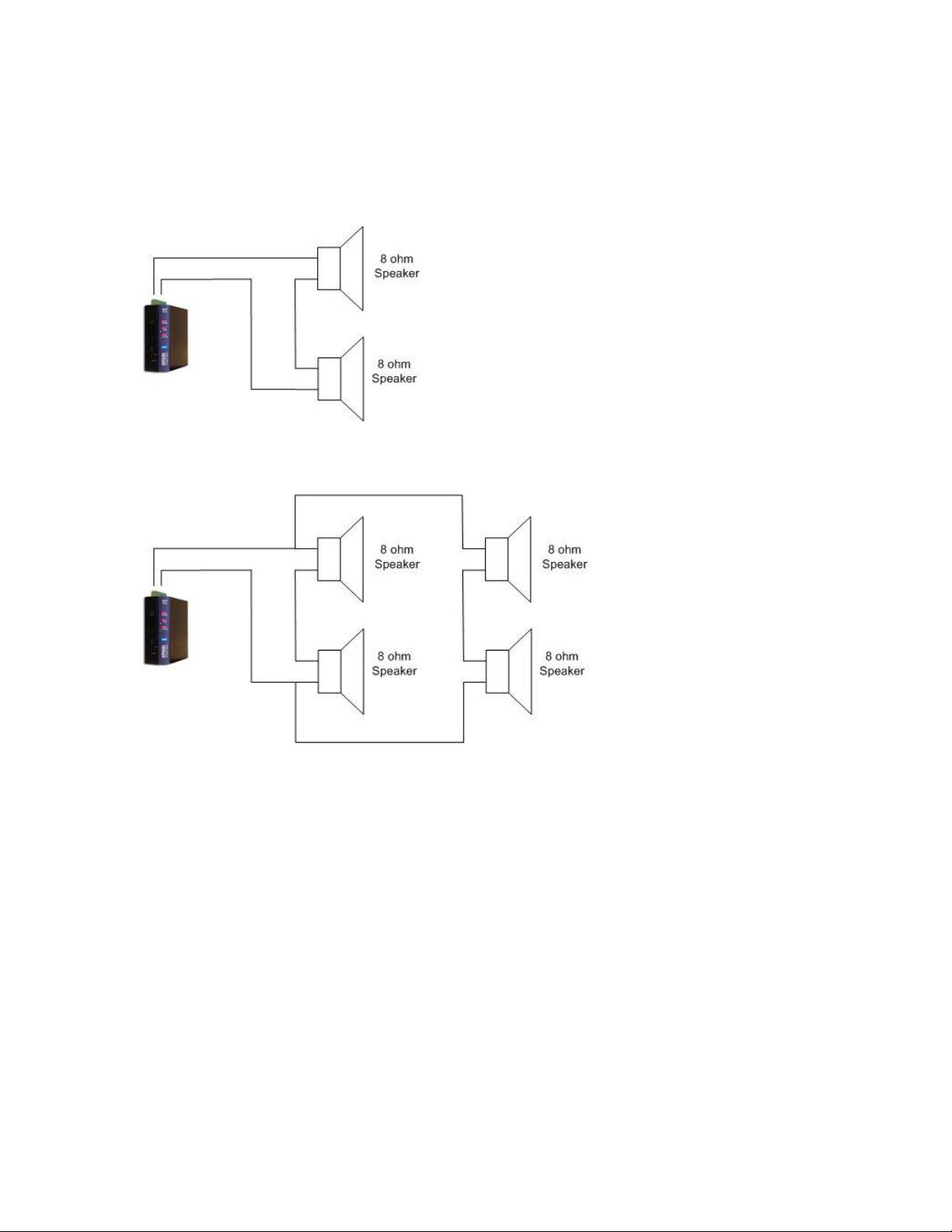
The IP7-FX is also capable of driving multiple 8 Ohm speakers without
25/70V transformers.
• Two 8 Ohm speakers must be wired in series
• Four 8 Ohm speakers must be wired in series-parallel
Please note the following guidelines:
• Connect the Speakers to the J2-6 (SPKR 8Ω+) and J2-7 (SPKR
8Ω-) (polarity independent)
• Speakers should be installed within 200 feet (60 meters) of the
IP7-FX using 18-gauge wire
• The total watts available from the IP7-FX are distributed equally
among the speakers so they will all have the same volume
Page 17

Page 13
Line Out
The Line Out generates a standard 2Vpp signal (two Volts peak to peak) to
drive a Line In signal.
To connect Line Out to a standard Line In signal, amplifier or amplified
speaker:
• Use 18-20 AWG shielded wire
• Connect J2-3 (Line Out) to the amplifier’s “+” connector
• Connect J2-4 (GND) and the amplifier’s “-“ connector
• Follow amplifier manufacture’s recommendations for balanced vs
unbalanced audio signals.
• If any noise is heard in the output signal, connect the J2-4 (GND) to
the negative terminal on the amplifier’s power source
Line In
The Line In is an alternate audio input and must be selected as the Input
Source instead of the Microphone in the IP7-FX software configuration.
Some devices that require a Line In are Line Level Microphones, Microphone
mixers, mobile phones or analog amplifiers.
To connect Line In:
• Use 18-20 AWG shielded wire
• Connect J3-4 (Line In) to the device’s “+” connector
• Connect J3-6 (GND) to the device’s “-“ connector
• Connect J3-6 (GND) to the shield and leave it floated at the line in
device
• Connect the shield to the device’s ground connector
Talk (Call) Button
The optional Talk Button connector is used to initiate a call to the
TalkMaster software or to a SIP Server.
To wire the Talk Button, connect J2-5 (Talk) to the Button, and then
connect J2-4 (GND) to the Button’s other contact. Optionally, the Button’s
other contact can be attached directly to one of the Speaker terminals. Use
18 AWG wire.
Dry Contact Relay
The Relay connector provides a dry contact output from the IP7-FX suitable
for activating equipment such as electronic door strikes, strobe lights or
CCTV cameras. Normally Open (N/O) or Normally Closed (N/C) can be
chosen. Use 18 AWG wire.
Page 18

Page 14
The Relay is rated at 250 VAC / 30VDC @ 60W / 1500 VAC Isolation.
• Connect either J3-1 (NO) for a normally open relay or J3-3 (NC) for a
normally closed relay to the device to be controlled
• Connect J3-2 (Common) to the other side
• Ensure Relay has been properly configured in the Intercom’s Software
Configuration program
SNSR/3.3V
The IP7-FX supports an input sensor that can be used for a variety of
applications. The sensor can be defined as Active when closed to ground
or Active when open to ground via software. Digital Acoustics’
TalkMaster™ Software provides functionality for monitoring the status (open
or closed) of a door via the sensor.
• Connect J3-5 (SNSR/3.3V) and J3-6 (GND) to a door sensor or device
that can provide a contact closure
• Ensure Sensor has been configured to be Activate when closed to
ground or Activate when open to ground in the IP7-FX’s software
configuration
Optionally, this connector can be used to power an LED at 3.3V (current
limited).
• Connect J3-5 (SNSR/3.3V) to the positive side of the LED and J3-6
(GND) to the negative side
• Ensure Sensor has been configured to Activate when open to
ground in the IP7-FX’s software configuration to prevent the sensor
alert from being generated
Page 19
Page 15
Mounting Instructions
The IP7-FX can be installed on a DIN Rail or surface mounted.
Din Rail Mounting
To DIN rail mount:
• Cut a piece of 35mm DIN rail (not supplied) to the desired length and
secure it to the location
• Place the IP7-FX onto the DIN rail by tilting the top of the unit (J1, J2,
J3 connectors facing up with Volume buttons and USB-B connector
facing forward) back towards the DIN Rail until the IP7-FXs DIN clip
catches the top of the rail
• Press in at the bottom of the IP7-FX to snap it in place
Surface Mounting
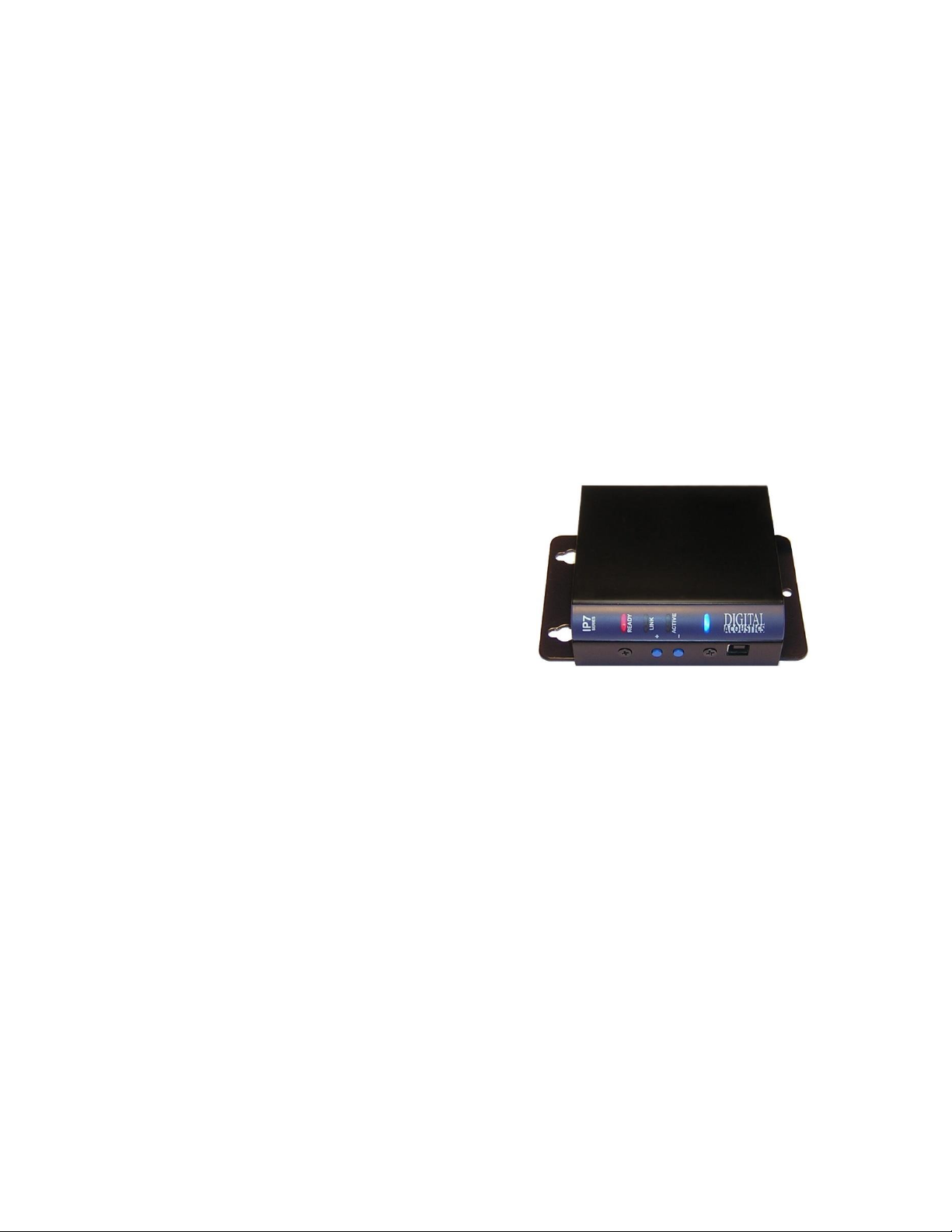
To attach the surface mount plate to the IP7-FX:
• Snap the plastic mounting plate in
half at the score marks
• Line up the two pieces of the surface
mount plate to the back of the unit.
The two mounting holes of the
surface mount plate should be above
the J1, J2, and J3 connectors
• Attach the two halves of the plate
using the four machine screws
included in the package
• Attach two (2) #8 pan head screws 2” (52 mm) apart and screw in to
within ¼”
• Place the mounting holes of the IP7-FX over the #8 screws
Setting Volume Levels
The IP7-FX supports seven volume levels for an attached speaker.
• Press the “+” or “- “ button one time to increase or decrease the
speaker volume
• If the IP7-FX’s Ready and Link LEDs are on solid, a high frequency
beep is heard when the volume “+” is pressed and a low frequency
beep is heard when the volume “-” is pressed
• Pressing the “-” or “+“ button seven times sets the unit at its lowest or
highest setting.
• Refer to the software manuals for setting the volume via software.
Page 20
Page 16
Configuration
Refer to the TalkMaster Administrator Reference Manual or the eSIP
Configuration utility software manuals for instructions on setting the IP
address information and optional settings for the IP7-FX.
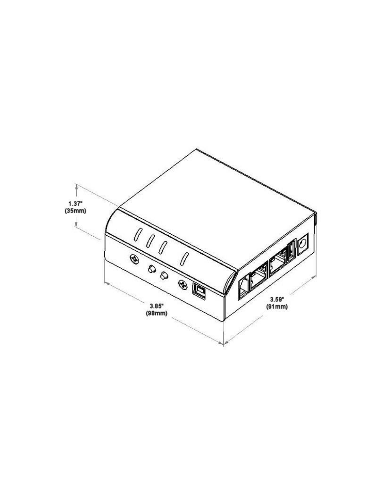
Physical Dimensions
The IP7-FX dimensions are as follows:
Environmental
The IP7-FX is designed to operate indoors or in a weatherproof box that has
a NEMA4 or IP66 rating.
Page 21

Page 17
Troubleshooting
Always refer the LED Indicator table when troubleshooting the IP7-FX.
Reset to Factory Defaults
The IP Address information and all Intercom options can be reset to factory
defaults by the following procedure:
• Unplug the Power
• Press and hold the “Vol +” and “Vol -“ buttons
• Power the unit
• Wait till the unit plays a 3-tone beep (about 5-8 seconds)
• Release the “Vol +” and “Vol -“ buttons
• Refer to the software manuals for instructions on setting the IP
address information
Connecting 1/8” (3.5mm) Audio Plug to the Pluggable connectors
To connect a Mic, Line In or Line Out to the pluggable connectors via a 1/8”
audio plug, the audio plug should be wired as follows:
• The Tip should be wired to positive
• The Sleeve should be wired to minus or ground
• On stereo plugs, the Ring should be left unconnected
Reducing electrical noise in audio
Improper wiring can cause noisy audio when transmitting microphone audio
from the IP7-FX. To minimize the possibility of this:
• Locate the unit at least one meter away from transformers, stepper
motors or other noise producing equipment
• Use shielded twisted multi-conductor cable for microphone audio and
follow the grounding recommendations
• Do not run audio cable in the same conduit with AC power
• Attached J3-6 to an earth ground
Viewing tech support info via the USB port
If requested by Digital Acoustics Support, a USB cable can be attached to the
IP7-FX to capture additional information.
• Attach a USB cable to the USB-B connector on the unit.
• Attach the other end of the cable to a PC running Windows®.
• Open the Windows Device Manager to determine the virtual Serial port
that has been assigned
Page 22

Page 18
• From the Windows Start menu, open a terminal emulation program
such as Teraterm and set the properties to select the new Serial port
with settings of 115kbs, 8,N,1, no flow control and ANSI Terminal
• Press the Enter key
• Provide the requested info to Digital Acoustics Tech support
Low Level Flashing Utility
If a power is removed from the unit while the firmware is being updated from
the network, the unit may require a low-level flash.
• Install the SAFMA - Low Level Flashing Utility from the TalkMaster
installation CD
• Perform the Phase 1 Reset procedure, followed by the Phase 2 Flashing
procedure
• If the Phase 1 Reset Procedure fails:
o Remove the four screws (two on the front and two on the back)
o Open the case by pulling up on the side opposite the Volume
buttons till the top pops off
o Connect the USB cable (this will power the unit up)
o Position the unit with the Vol “+” and Vol “-“ buttons facing you
o Bend a paper clip or piece of wire and insert into the two holes to
the right of the Vol “+” and Vol “-“ buttons
o Power cycle the unit by removing and reinserting the USB cable
o Run the SAFMA utility and perform the Phase 2 Flashing procedure
o Verify by repowering the IP7
Technical Support
Technical support information is available online at www.digitalacoustics.com
under the Support menu.
Email support:
Page 23

Page 19
Regulatory Notices
Federal Communication Commission Class A Notice
This equipment has been tested and found to comply with the limits for a Class A
digital device, pursuant to Part 15 of the FCC Rules. These limits are designed to
provide reasonable protection against harmful interference when the equipment is
operated in a commercial environment. This equipment generates, uses, and can
radiate radio frequency energy and, if not installed and used in accordance with the
instruction manual, may cause harmful interference to radio communications.
Operation of this equipment in a residential area is likely to cause harmful
interference in which case the user will be required to correct the interference at his
own expense.
In compliance with FCC regulations, the following information is provided on the
device or devices covered in this document.
• Product Name: IP7 Series
• Model number: FX
• Company name: Digital Acoustics LLC
37 Sherwood Terrace
Lake Bluff, IL 60044
847-604-9246
IC Notice (Canada Only)
This Class A digital apparatus complies with Canadian ICES-003.
Cet appareil numérique de la classe A est conforme à la norme NMB-003 du
Canada.
NOTE: Industry Canada regulations provide that changes or modifications not
expressly approved by Digital Acoustics, LLC could void your authority to operate
this equipment
CE Notice
Marking by the symbol indicates compliance of this equipment to the EMC
(Electromagnetic Compatibility) directive of the European Community. Such marking
is indicative that this equipment meets or exceeds at least an EN 55022:2006
Class A device
VCCI Compliance
Class A
AS/NZS CISPR22:2006 Compliance
Class A
CNS 13438 Compliance
Class A
Page 24

Index
A
Aux Power ................................ 4
C
CASE ....................................... 5
Common .................................. 5
D
DIN rail mount ......................... 15
DIN Rail Mounting Clip ............... 4
E
Earth ground ............................ 5
Ethernet 10/100 ........................ 4
Ext I/O ..................................... 4
External Power .......................... 8
G
GND ........................................ 5
Ground..................................... 5
L
LED ......................................... 6
LED Status ............................... 6
LINE IN .................................... 5
Line Out ................................... 5
M
MIC - ....................................... 5
MIC + ...................................... 5
N
Normally Closed ........................ 5
Normally Open .......................... 5
P
PoE .......................................... 7
Port 2 10/100 ........................... 4
Power ...................................... 5
Power - .................................... 5
R
Relay connector ....................... 13
S
SENSOR ................................... 5
SPKR 8Ω- ................................. 5
SPKR 8Ω+ ................................ 5
T
TALK ........................................ 5
Talk connector ......................... 13
U
USB Power ............................... 8
USB-B ...................................... 4
V
Volume ................................... 15
Volume Down ........................... 4
Volume Up ............................... 4
Page 25

Notes
Page 26

www.digitalacoustics.com
Digital Acoustics' product designs are packaged by
leading manufacturers around the world. Contact factory
for technical specification before product design and/or
use. Design and specification are subject to change
without notice.
Digital Acoustics®, IP7™, ii3™ and TalkMaster™ are
trademarks of Digital Acoustics, LLC. I2C is a registered
trademark of NXP Semiconductors, Inc. All other marks
used are properties of their respective owners.
Copyright 2019, All Rights Reserved
IP7-FX Reference Manual.docxu 2019-08-16-20
 Loading...