

Digital Acoustics IP7-FD Reference Manual
IP7™-FD
IP Intercom/Amplifier
Reference Manual

This page left blank

i
Table of Contents
Overview ................................................................................... - 1 -
Specifications ............................................................................ - 2 -
IP7-FD Layout ............................................................................ - 3 -
LED Indicators ........................................................................... - 6 -
Connecting to an Ethernet Network ........................................... - 7 -
Connecting Power ...................................................................... - 7 -
PoE ............................................................................................. - 7 -
External Power ............................................................................. - 7 -
USB Power ................................................................................... - 7 -
Audio - Mic and Speaker ............................................................ - 8 -
Understanding Full Duplex Audio .................................................... - 8 -
IP7-FD Panel Models and Installations ............................................. - 8 -
Wiring Overview ........................................................................... - 9 -
Wiring to FD Panels ..................................................................... - 10 -
Wiring the FD Panels - Summary .................................................. - 11 -
Connecting the Relay ............................................................... - 12 -
Connecting the Sensor ............................................................. - 12 -
Alternate Operational Modes ................................................... - 13 -
Line In ...................................................................................... - 13 -
External Microphone Connection Mode ........................................... - 13 -
Mounting Instructions ............................................................. - 14 -
Din Rail Mounting ....................................................................... - 14 -
Surface Mounting ........................................................................ - 14 -
Setting Volume Levels ............................................................. - 14 -
Configuration ........................................................................... - 15 -
IP Configuration.......................................................................... - 15 -
Intercom Options ........................................................................ - 15 -
Physical Dimensions ................................................................ - 16 -
Environmental ......................................................................... - 16 -
Troubleshooting ....................................................................... - 17 -
Reset to Factory Defaults ............................................................. - 17 -
Connecting 1/8” (3.5mm) Audio Plug to the Pluggable connectors .... - 17 -
Reducing electrical noise in audio .................................................. - 17 -
Viewing tech support info via the USB port ..................................... - 17 -
Low Level Flashing Utility ............................................................. - 18 -
Contacting Technical Support .................................................. - 18 -
Regulatory Notices .................................................................. - 19 -
Index ....................................................................................... - 20 -
Overview
The Digital Acoustics IP7-FD is an IP (Internet Protocol) 2-way intercom with
an integrated output amplifier, relay, sensor and 2-port network switch.
The “FD” is designed to work in tandem with Digital Acoustics FD “Full
Duplex” panels and enclosures to support high definition Full Duplex audio
and simultaneous 2-way hands free conversations.
Standard features of the IP7-FD include:
• IP connectivity for Intercom and Paging with TalkMaster™ and SIP
based VoIP telephones
• Full duplex audio when used in conjunction with ‘FD’ series wall panels
• Highly scalable, seamless expansion
• Paging capability
• Mounting via rail or surface mount
• Fixed or DHCP compliant IP assignment
• Auto sensing power from 12VDC - 15VDC
• PoE (802.3af) standard
• Integrated 2-port switch
• Field upgradeable OS
The IP7-FD must be configured using the TalkMaster software before
being used. Please consult the configuration section of the software
manual for details.
!

Specifications
Items
Specification
Network Protocols
TCP, UDP, SIP, RTP, ICMP, IGMP Multicast
Network Interface
10/100 Ethernet (Auto detection, Auto MDIX)
Command protocols
Proprietary and Standards Based
Audio Resolution
G.711 (8-bit PCM and 16-bit uLaw)
Audio Sample Rate
8K (Voice band) , 22K (Background Music)
Audio Frequency
90-4kHz (Voice band) , 90-11khz (Background Music)
Internal Amplifier
8 watt @ 8 Ohms 1% THD
Humidity
10~90%
Power
External Power 12-15 VDC @ 15 watts nominal.
PoE (802.3af) compliant (requires 15.4 watts from
PSE). External Power overrides PoE power
Size
3.85. x 3.59 x 1.37 in
98 mm x 91mm x 35mm
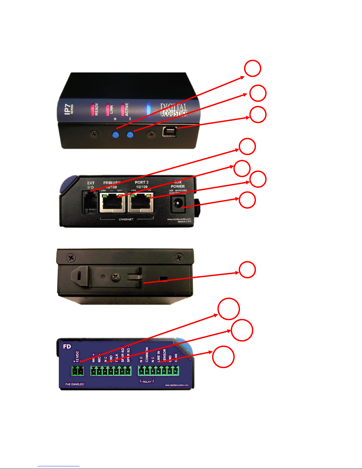
IP7-FD Layout
1 2 3 4 6
7
J1
8
5
J2
J3
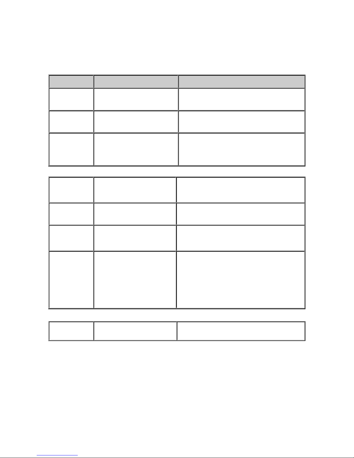
Connections and Controls
Refer to the preceding pictures.
Connector
Connector / Control
Notes
1
+ Button
Volume up button
2
- Button
Volume down button
3
USB-B
Provides for low level firmware flashing
as well as viewing technical support
information. Will also power the unit for
diagnostic purposes.
4
Ext I/O
I2C expansion bus interface that can be
used for custom applications. Requires
custom firmware from Digital Acoustics
5
Ethernet 10/100
10/100 Ethernet network interface.
Supports auto negotiation and auto-MDIX
6
Port 2 10/100
Provides a 10/100 Ethernet network
connection for another device. Supports
auto negotiation and auto-MDIX
7
Aux Power
2.1mm power connector with center tip
positive. 12VDC - 15VDC @ 15 watts.
Overrides PoE power.
Warning: Connecting power to both the
2.1mm Power jack and the J1-1 and J1-2
power connectors at the same time will
damage the unit
8
DIN Rail Mounting Clip
Allows unit to be snapped on to standard
35mm DIN Rail stock
There are three sets of pluggable DIN connectors (3.81mm centers) on the
FD:
J1 Connector
J2 Connector
J3 Connector
LED Indicators
Intercom LEDs
Connector
Signal
Notes
J1-1
Power +
12VDC at 15 watts. Overrides PoE power.
Warning: Connecting power to both the 2.1mm power jack and the
J1-1 and J1-2 power connectors at the same time will damage the
unit
J1-2
Power -
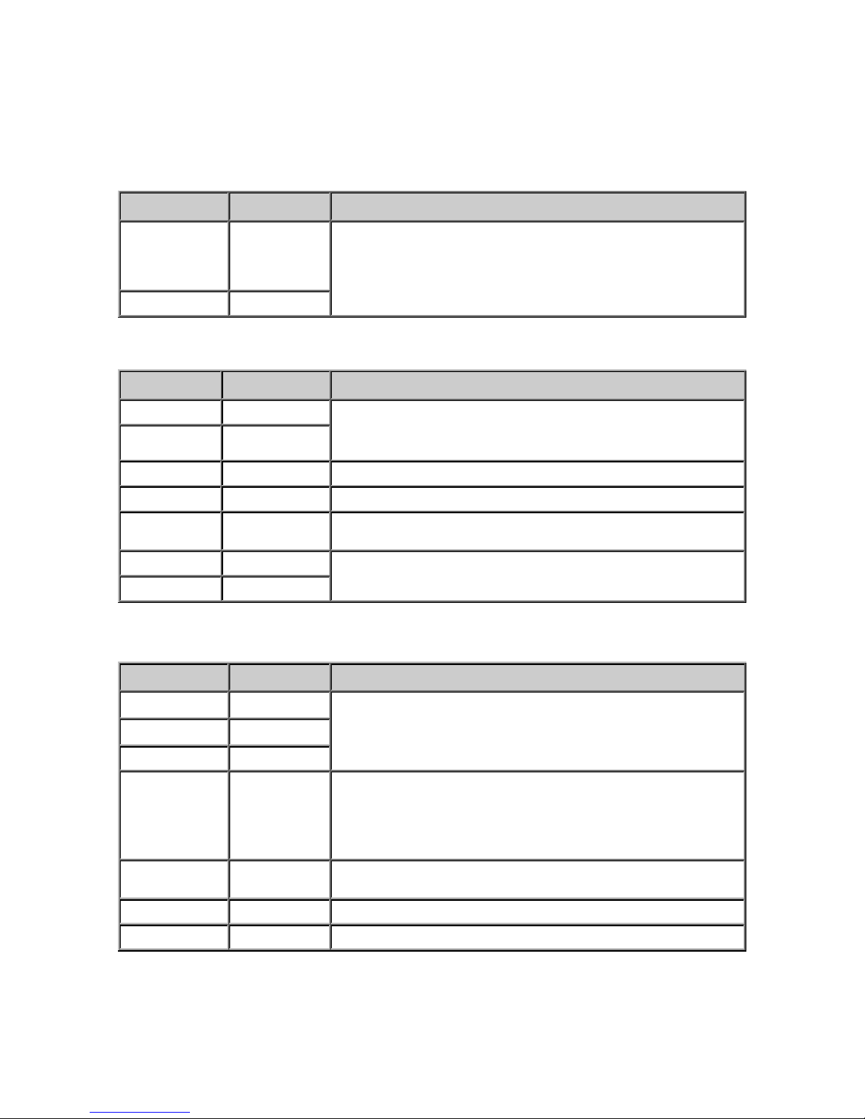
Connector
Signal
Notes
J2-1
MIC +
Microphone Inputs. Pseudo differential (Actively Balanced
differential).
Also capable of accepting Line In signal
J2-2
MIC -
J2-3
N/C
This connector is not used
J2-4
GND
System Ground. Same as J3-6
J2-5
TALK
Talk or Call button. Initiates a call to the configured Server.
Reference to J2-4
J2-6
SPKR 8Ω+
Floated differential output. Able to drive an 8 Ohm load @ 8 watts or
a 600 Ohm load
J2-7
SPKR 8Ω-
Connector
Signal
Notes
J3-1
NO
Isolated Dry Contact Relay output. Connect J3-2 and either J3-1 for
NO (Normally Open) or J3-3 for NC (Normally Closed)
J3-2
COMMON
J3-3
NC
J3-4
LINE IN
Multi Use Connector
Speaker Mix - Audio is sent directly to the Speaker Outputs (default
action). Unbalanced. Reference to J3-6
Standard Line In - Unbalanced. Reference to J3-6. Requires special
Audio Profile. This will bypass Acoustic Echo Cancellation!
J3-5
SENSOR
Door Sensor. Active when closed to ground or Active when open to
ground. Reference to J3-6
J3-6
GND
System Ground. Same as J2-4
J3-7
CASE
Optional connection to earth ground
 Loading...