

Page 1
ii3 IP Intercom
Users′ Guide
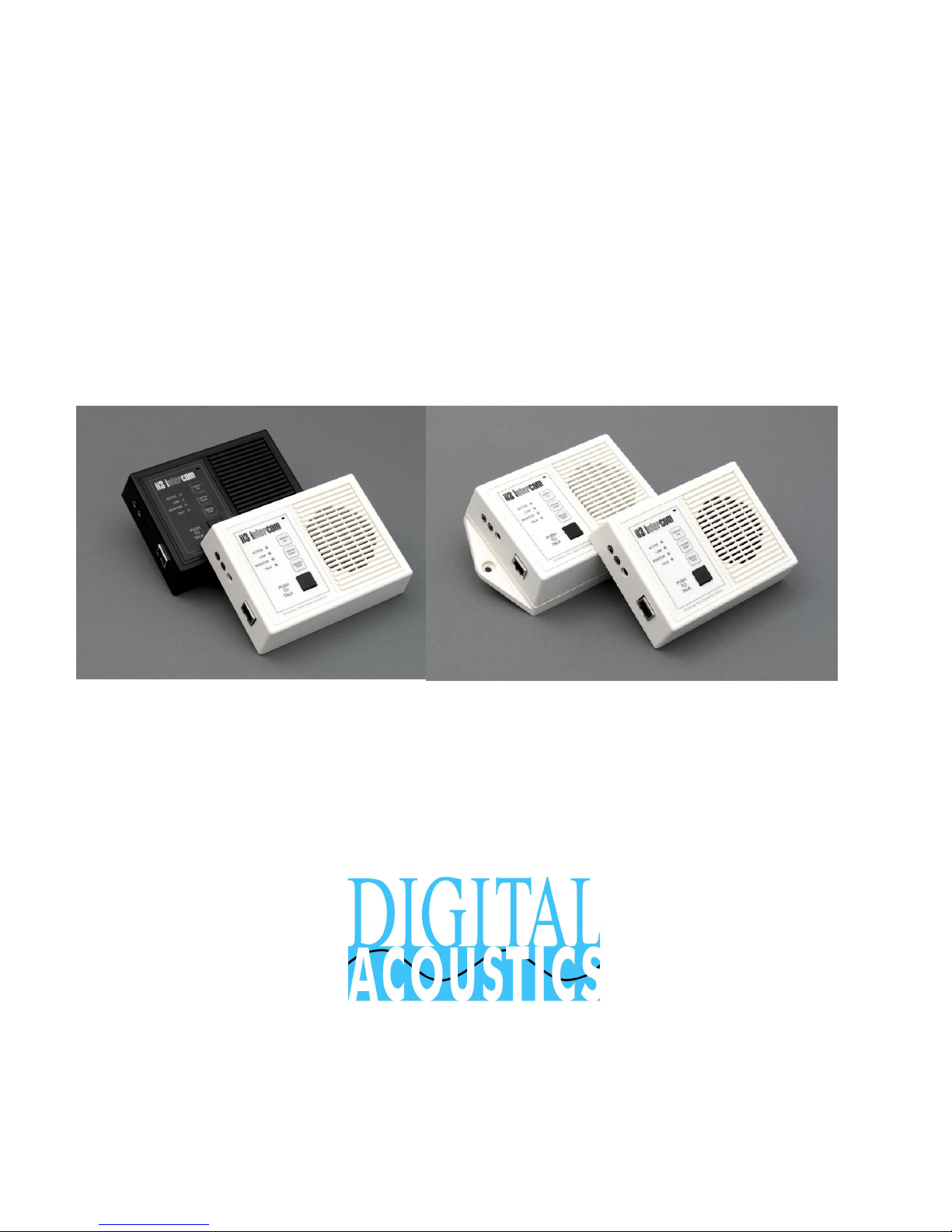
Model ED series
Model ES series
Page 2

This page intentionally left blank
Page 3

TABLE OF CONTENTS
OVERVIEW ................................................................................4
SPECIFICATIONS......................................................................5
INTERFACE CONNECTIONS ....................................................6
INTERFACE CONNECTION DETAIL .........................................6
CONFIGURATION AND IP ADDRESSES ..................................7
TYPICAL SYSTEM CONFIGURATIONS ....................................8
INTEGRATED SWITCHES.........................................................9
LED INDICATORS....................................................................10
EXTERNAL MICROPHONE SELECTION ................................11
EXTERNAL SPEAKER CONNECTIONS.................................11
NETWORK WIRING USING CAT5...........................................11
SOFTWARE SUPPORT ...........................................................12
FIRMWARE OS UPGRADES ...................................................15
TROUBLESHOOTING..............................................................14
INTEGRATED 2-PORT SWITCH OPTION ...............................13
POE OPTION ...........................................................................14
TECHNICAL SUPPORT ...........................................................14
- 3 -
Page 4

O
VERVIEW
Digital Acoustics IP (Internet Protocol) Intercom modules provide
a functional audio equivalent to the basic "push to talk" (PTT)
intercom. Features include:
Talk to/from any station to host PC server
High quality, clear transmit and playback audio
Simple operation utilizes push buttons for commands
Fixed and automatic and DHCP compliant IP assignment
Integrated 2-port switch option available
PoE (802.3af) option available
Hands-free listen mode at stations
Highly scaleable and seamless expansion
Field upgradeable OS using internal Flash memory
TalkMaster™ host software access and controls ii3 clients
The ED desktop series includes the following models:
• EDB-110/220 - Externally powered black PVC desktop
• EDBx-110/220 - Externally powered w/2-Port switch black
PVC desktop
• EDB-PoE - PoE powered black PVC desktop
• EDBx-PoE - PoE powered w/2-port switch black PVC
desktop
• EDW-110/220 - Externally powered white PVC desktop
• EDWx-110/220 - Externally powered w/2-Port switch
white PVC desktop
• EDW-PoE - PoE powered white PVC desktop
• EDWx-PoE- PoE powered w/2-port switch white PVC
desktop
The ES surface mount series includes the following models:
• ESB-110/220 - Externally powered black PVC wall mount
• ESBx-110/220 - Externally powered w/2-Port switch black
PVC wall mount
• ESB-PoE - PoE powered black PVC wall mount
• ESBx-PoE - PoE powered w/2-port switch black PVC wall
mount
• ESW-110/220 - Externally powered white PVC wall mount
• ESWx-110/220 - Externally powered w/2-Port switch
white PVC wall mount
• ESW-PoE - PoE powered white PVC wall mount
• ESWx-PoE- PoE powered w/2-port switch white PVC wall
mount
- 4 -
Page 5

S
PECIFICATIONS
Items Specification
Hardware Protocols
Network Interface
Command protocols Proprietary
Audio Rate 64kbs
Audio Resolution PCM-8bit and uLAW-16 bit 8bit
Audio Sample Rate 8 kHz (Voice band)
Audio Buffers 4KB TX and RX
Internal Amplifier 2w Max @ 4 ohms
Microphone sensitivity -42db integrated electret
Microphone AGC
PHY Interface
Temperature
TCP, UDP, IP, ARP, ICMP, Ethernet
MAC
10/100 Base-T Ethernet (Auto
detection)
37db with limiting and automatic
leveling
RealTek RTL8201BL single-port
PHYceiver
0'C ~ 70'C (Operating)
-40~85'C (Storage)
Humidity 10~90%
Power
Connector types
Size 135mm x 102mm x 37mm
Weight 7.5oz (213 grams)
- 5 -
Without integrated 2-port
switch: 7.5-9 VDC external power
supply or 5 VDC through header
pins (500MA min)
Optional integrated 2-port
switch: 5VDC (750mA min)
Optional PoE (Power over
Ethernet 802.3af standard) 7watts
Power 2.1 mm (positive center)
Audio 3.5 mm
Page 6
Microphone
I
NTERFACE CONNECTIONS
External
Microphone
Input
Audio Out
Power
Internal
Internal
Speaker
LAN 10/100
RJ-45
I
NTERFACE CONNECTION DETAIL
EXTERNAL CONNECTIONS
LAN
10/100
MIC
INPUT
JACK
AUDIO
OUT
JACK
RJ-45
3.5MM
3.5MM
TCP, UDP, IP, ARP, ICMP, 10/100 Base-T Ethernet
(Auto detection) MAC
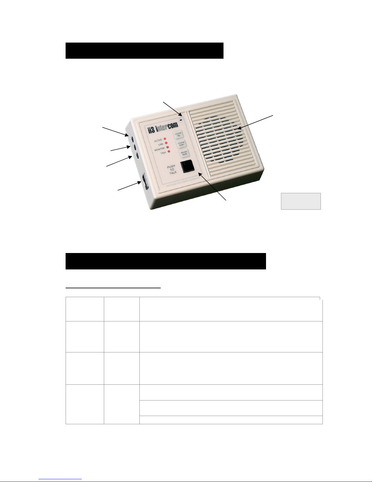
External Microphone Input. Use of this jack automatically
disconnects the onboard electret microphone. See
following section for recommended microphone
specifications
External audio out jack. Capable of driving headphones
or external amplifier. Use of this jack interrupts connection
to onboard speaker.
Talk Button
Version shown
Ii3-EDW
POWER
JACK
- 6 -
2.1 MM
Models without integrated 2-port switch use unregulated
DC input 7.5VDC to 9VC 500ma. POSITIVE TIP polarity
Models with integrated 2-port switch use regulated DC
5.0VDC 750ma. . POSITIVE TIP polarity
Do not use concurrently with optional PoE supply
Page 7
C
ONFIGURATION AND
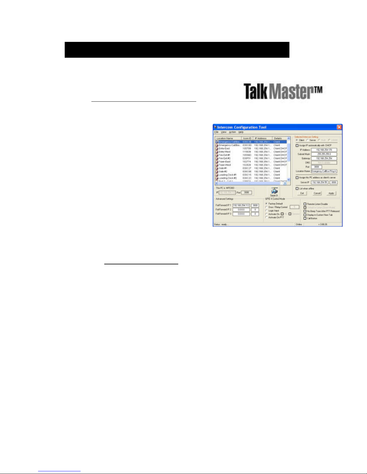
TalkMaster™ LE software is included with the
purchase of any ii3 IP Intercom.
Access www.digitalacoustics.com/ii3 for
downloads and more information.
Quick reference:
1. Install and start TalkMaster™ software
2. To configure your intercoms, select
menu option Admin Enable Admin
(default password is: admin)
3. Select menu option Admin Configure
Intercoms
4. Select and assign intercom’s IP address,
Subnet and Gateway
5. Assign a Location Name to the
Intercom
6. Assign the Server IP address the
Intercom will connect to
7. Click Apply
8. Click Exit
Refer to the TalkMaster User Guide for more information on setup and
configuration options!
IP A
DDRESSES
- 7 -
Page 8
T
YPICAL SYSTEM CONFIGURATIONS
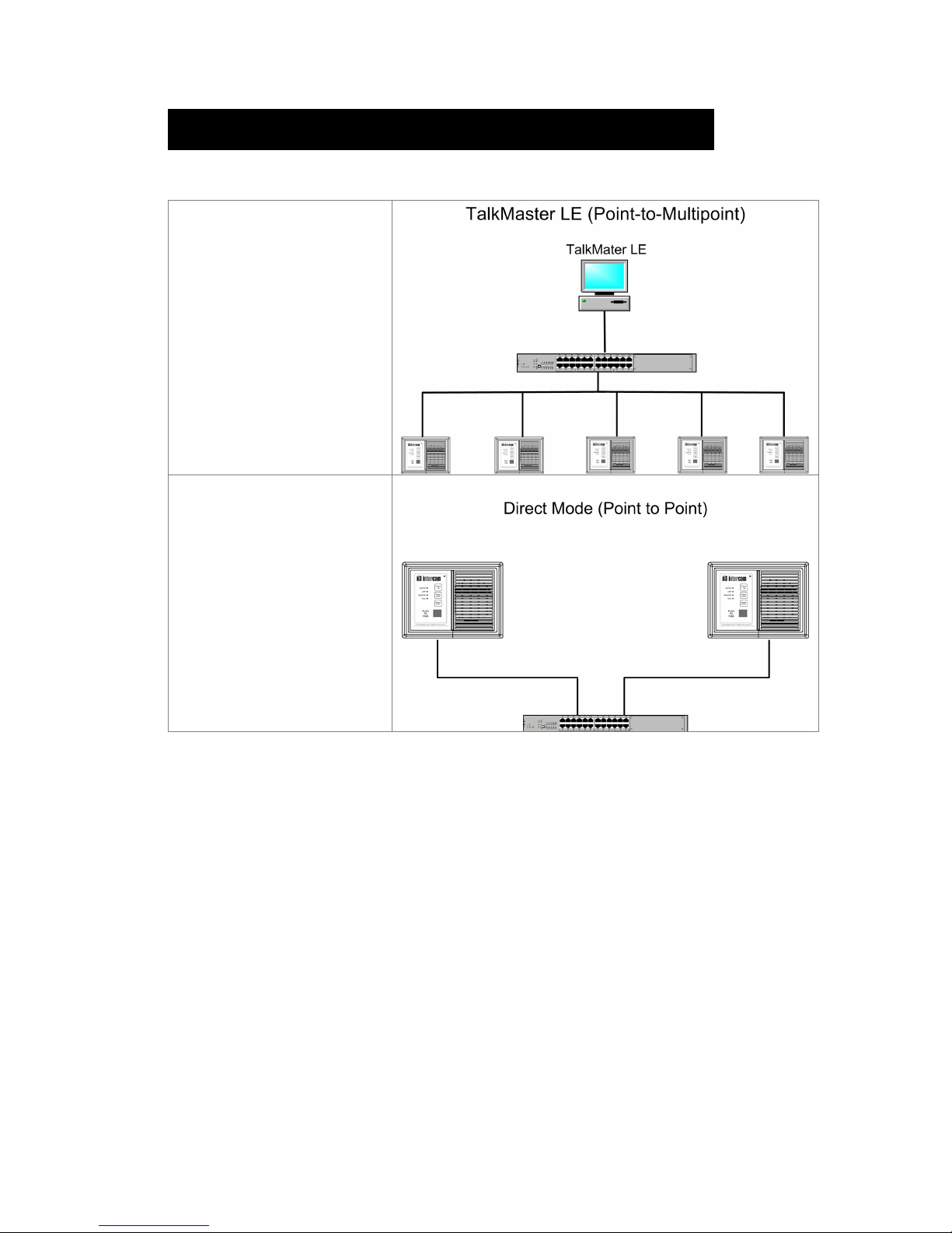
PC-SERVER
MODE
Server PC with
TalkMaster™ software
connected to Intercom
Client array
DIRECT
MODE
One ii3 Intercom
configured as 'Server' ,
connected to a another
as 'Client'
- 8 -
Page 9

I
NTEGRATED SWITCHES
Talk
Monitor/Open
Volume Up
Volume Down
Push to Talk. Turns on local microphone.
• In 'Client' mode, Monitor sets 'Talk' ON, as if the Talk
button is being held down for hands free speaking.
• In 'Server' mode quickly pressing Monitor turns on listen
mode on by turning the Client Intercom’s microphone on.
Press Talk to talk to the Client Intercom. Quickly
pressing Monitor a second time turns off remote
listening
• In ‘Server’ mode (Direct Mode), pressing and holding
this button activates the GPIO4 or the relay (dry contact)
on the “Client Intercom”
Sets volume locally (also set via TalkMaster). There
are 7 (seven) volume level settings.
- 9 -
Page 10

LED INDICATORS
The four LEDs marked Active, Link, Monitor/Open and Talk can provide the
following diagnostic information:
Operational Mode Active Link
Monitor/
Open
Talk
Normal operational mode. TalkMaster
is active. Intercom can communicate.
LAN connection is inactive. The RJ45
may be unplugged, or the cable may
be defective.
Intercom has not been configured yet
or has been configured for DHCP, but
no DHCP Server is available. To turn
off DHCP, power cycle the Intercom
while holding down the + and - buttons
(Volume up and Volume down)
TalkMaster™ Server software is not
running or not set to communicate.
TalkMaster software at the server has
"Searched" for intercoms in the
Configuration Mode utility setup
Receiving audio. The server software
(TalkMaster™) / PC microphone is on.
Sending audio. Talk button is pressed
or server has engaged "listen" mode.
Intercom is in "Server" mode, waiting
for a client to request connection
(Active LED flash alternates 1sec fast - 1sec slow)
ON ON - -
FLASH OFF - -
FLASH ON - ON
FLASH ON - -
FAST
FLASH
ON ON - FLASH
ON ON - ON
DUAL
FLASH
ON - -
- - -
Local "Monitor" button has been
depressed. Microphone is set to
constant "Talk" mode for monitoring
- 10 -
ON ON ON ON
Page 11
E
XTERNAL MICROPHONE SELECTION
ii3 supports high quality voiceband audio. Integrated AGC amplifiers
support a wide range of microphone inputs and low cost electret
microphones ($3usd) will have similar intelligibility as expensive
"professional" microphones ($10-$50usd). Microphones mounted
externally should be in a vibration and moisture free environment.
E
XTERNAL SPEAKER CONNECTIONS
A 3.5mm Audio Out jack is provided for headphones, external
speaker or an amplifier. When connecting speakers to the Audio
Out jack, user an external amplifier or powered speakers
N
ETWORK WIRING USING
CAT5
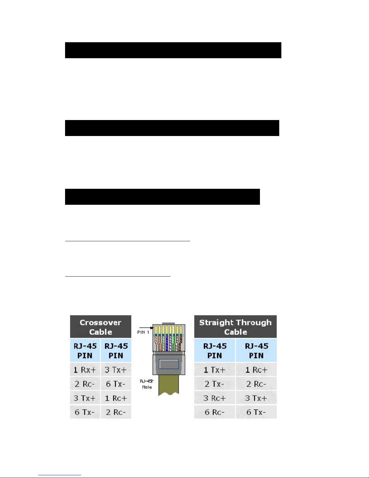
Ii3 series products connect to network hubs and switches using
standard Straight Through wiring, similar to PC connections and
do not support mdi auto-detection. No special connections or
cabling changes are needed under normal operating
environments.
Crossover Cable Connections
Use a Crossover cable ONLY when using 2 ii3 intercoms in DIRECT
CONNECTION (Server/Client) or when using a PC to single ii3
intercom WITHOUT a hub/switch interconnect.
Cat-5 Wiring reference
- 11 -
Page 12
S
OFTWARE SUPPORT
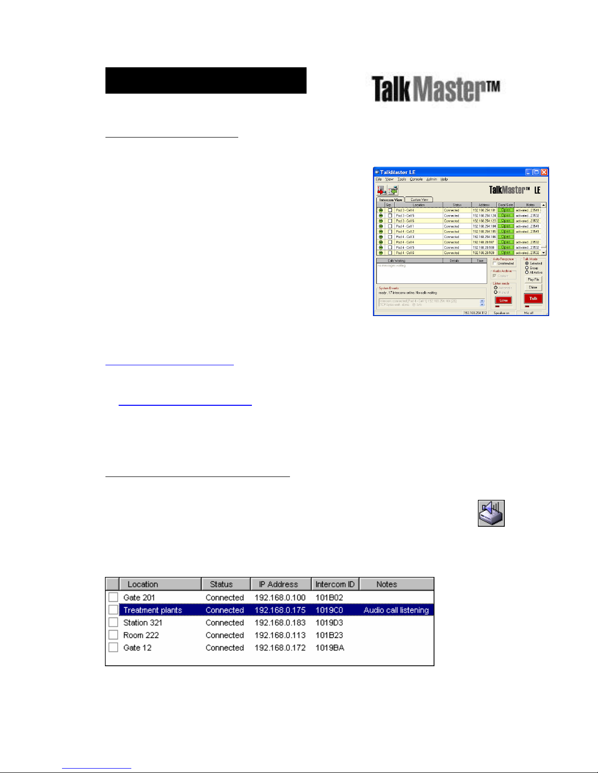
ii3-TalkMaster™ software
• Control and detection for intercom stations
• Audio access for all ii3 intercoms with Master
call to page all stations
• Program ii3 intercom internal OS/Flash memory
• Pop-up screens for identifying incoming station ID
and audio
• Utilizes PC Multimedia microphone/speaker for
access to intercoms
• Integrated UDP polling on to automatically
detects all stations
• ActiveX control available for easy custom GUIs
with sample program (C++)
• Windows® 98, Me, 2000, XP, Server 2003
TalkMaster™ software manuals and downloads are available at
www.digitalacoustics.com/ii3
If you require multiple concurrent consoles managing ii3 IP Intercoms, refer
to www.digitalacoustics.com for information on TalkMaster Enterprise
Edition software.
iTalk/X SDK development software
iTalk/X provides complete access to the functions used
in TalkMaster™, making it easy to write TCP/IP server
software for Digital Acoustics' ii3 Intercom Series. iTalk/X is
available as an ActiveX control for Visual Basic and Visual C++
applications, or and other GUIs that support ActiveX.
iTalk/XActiveX
- 12 -
Page 13
I
NTEGRATED
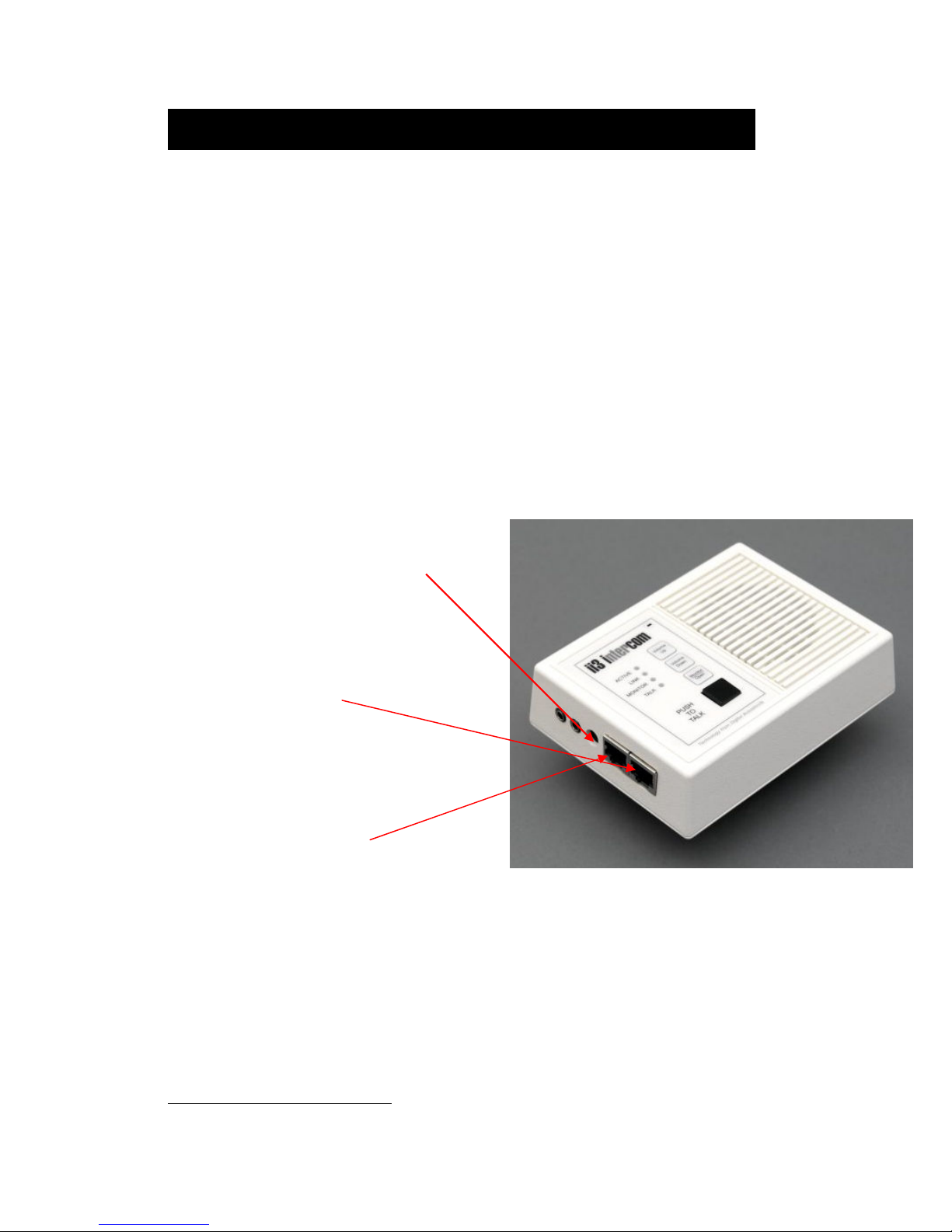
An integrated 2-port switch is an option available on all models of
the ED and ES series. The 2-port switch allows connection of an
additional IP device from a single network drop.
Important - ii3 intercoms with the integrated 2 port switch are
supplied with a regulated 5vdc (750mA) power supply. Other
intercoms in the ii3 series use 7.5vdc or 9vdc power supplies.
Using the wrong power supply could damage the unit.
• Connect a regulated 5vdc power
supply with 2.1mm plug, center
tip positive, min 750mA
• Connect an Ethernet cable from
a hub/switch into the RJ45
connector closest to the edge of
the intercom.
• Connect an Ethernet cable to
any other IP device using the
RJ45 connector that is next to
the power jack.1
2-
PORT SWITCH OPTION
Connecting ii3 Intercoms
With integrated 2 port switch
1
If the upstream device is another hub/switch that does not have mdix
capabilities, use a crossover cable
- 13 -
Page 14

Crossover Cable
POE O
PTION
A PoE (Power over Ethernet - 802.3af compatible) option is available on all
models in the ED and ES lines.
• Each ED or ES intercom will draw 7 Watts from your network switch
or injector
• On models with the PoE and integrated 2-port switch options, PoE
does not pass through to other devices connected to the 2nd port
• Do not plug power into the external power jack and connect the
Intercom to a PoE power source at the same time
T
ROUBLESHOOTING
Verify power connections. The "Active" or LD10 LED on should be on or
flashing.
Verify that the “Link” or LED is on solid. If not, a valid network
connection is not present.
ii3 Intercoms may operate across some firewalls or VPN's. They will
need to be configured locally (for setup) and will need to be assigned to
the STATIC IP addresses of the TalkMaster PC.
If the intercoms have been configured for DHCP and no DHCP server is
available, re-power the intercom while holding down the Volume Up and
Volume Down buttons. Wait 15 seconds, then Search for the Intercoms
again and assign a static IP address.
If you cannot detect any intercoms using the TalkMaster Intercom
Configuration Utility screen try directly connecting the PC (running
TalkMaster) to the ii3 intercom using a crossover cable (disconnected
from the network).
PC running
TalkMaster
ii3
intercom
To reset the Intercom’s configuration back to factory defaults, re-power
the intercom while holding down the TALK and Volume Up buttons.
This will erase the Intercom’s IP Address settings, Intercom Name and
all options. Wait 15 seconds, then Search for the Intercoms again and
re-configure the Intercom.
- 14 -
Page 15

F
IRMWARE
All ii3™ intercoms use internal Flash memory. Operating system
(OS) and firmware may be upgraded to include new revisions or
custom options. TalkMaster™ software is required to enable and
program the Flash memory upgrade feature.
T
ECHNICAL SUPPORT
Information online www.digitalacoustics.com/ii3
Email [email protected]
Telephone +1 (847) 604-9256 M-F 8-5 (Central Time Zone)
OS
UPGRADES
- 15 -
Page 16

This document may contain advance information. Contact factory for technical specification before
product design and/or use. Design and specifications are subject to change without notice.
Digital Acoustics® and TalkMaster™ are trademarks of Digital Acoustics Corporation, all other marks
used are properties of their respective owners. Digital Acoustics' product designs are packaged by
leading manufacturers around the world.
Digital Acoustics, LLC
263 Market Square • Lake Forest, IL 60045 U.S.A.
Office +1 847-604-9256
• Fax +1 847-604-9346
- 16 -
i3-m-1216D
Rev 2007-01-10-9
 Loading...