

DIGISYNTHETIC PRO DS216 Instruction Manual
OUTGAIN
PEQ
PROGRAM
STORE
SETUP
CH-SEL
POWER
MODE
CROSSOVER
PARAMETER
Instruction Manual
DIGITALCROSSOVER
CLIP
LIMIT
CLIP
LIMIT
CLIP
LIMIT
OUTPUTS
CLIP
LIMIT
CLIP
LIMIT
CLIP
LIMIT
-
-
3
-
CLIP
INPUTS
-
-
32BITDSP48KHZSAMPLINGRATE
6
12
30
18
24
-
-
-
-36-
MUTE
5
12
30
18
24
-
-
-
-36-
MUTE
4
12
30
18
24
-
-
-
-36-
MUTE
3
12
30
18
24
-
-
-
-36-
MUTE
2
12
30
18
24
-
-
-
-36-
MUTE
1
dB
12
30
18
24
-
-
-
-36-
MUTE
B
IN
-
-
-
-
-
-
6
dB
12
36
30
18
24
-
-
-
-
-
-
-
-
-
-
-
-
A
IN
INPUTB
INPUTA
D 216S
CROSSOVER
2~6 WAY OUT
DIGISYNTHETIC
24-BIT DIGITAL THREE CROSSOVER PROCESSOR MODEL DS216
DIGISYNTHETIC PRO
ATTENTION!
All DIGISYNTHETIC PRO products are carefully packed and designed to protect the units from rough handling
before shipping out from the factory. Examine your good upon receiving, to ensure no damage during transportation.
Any damage claim should be inform & notify to relative dealer within 14 days of good received. The dealer
will not except failing of such. The consignee must make all shipping claims.
The DS216 fits into a standard 19" rack unit of space (1 3/4"). Allow at least an additional 4" depth for the
connectors on the back panel. Be sure that there is enough air space around the unit for cooling and ventilation.
DO NOT place the DS216 on high temperature devices like power amplifiers etc. to avoid overheating.
Using a main cable and a standard IEC receptacle makes the main connection of the DS216. It meets all of the
international safety certification requirements.
Please make sure that all units have a proper ground connection. For your own safety, do not remove the ground
connection within the unit or at the supply, or fail to make this connection at all.
This machine is only intended for qualified personnel to operate & install. Do not attempt to repair and service
yourself but referred to qualified technical service personnel. The user must have sufficient electrical contact
to earth. Electrostatic charges might affect the operation of the DS216.
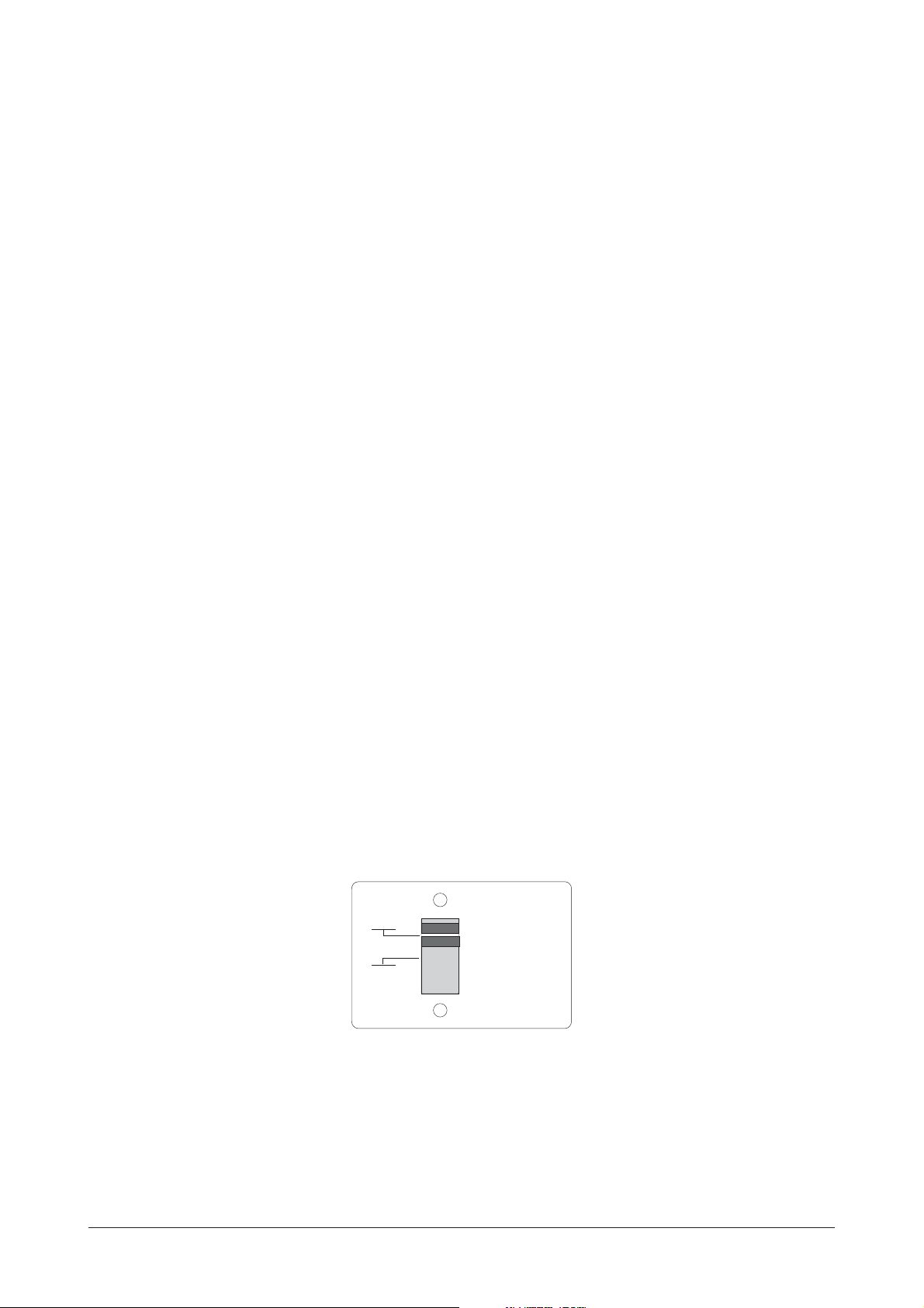
NOTICE: Before switching voltage for local supply requirement, correct fuse type and rate must be installed.
When the power supply is 220V/240V, fuse is 125mA; and the power supply is 110V/120V, fuse is changed
to 315mA. The switch is preseted to 220V/240V in the factory.
110V
120V
220V
240V
220V
CAUTION
THE POWER
SUPPLY CORD
SHOULD BE
DISCONNECTED
BEFORE
CHANGING
THE VOLTAGE
SELECTOR
1
DS216 Digital Three Crossover Processor
Operation Specification
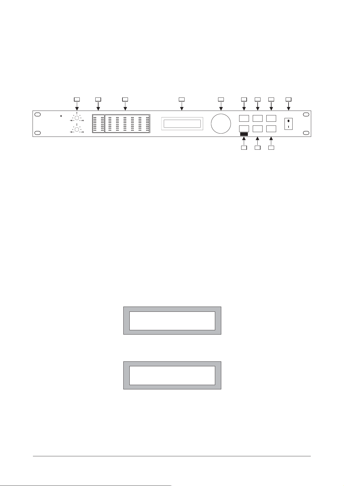
Front Panel
1 2 3 4
INPUTS OUTPUTS
-
-
CLIP
CLIP
CLIP
CLIP
CLIP
DIGISYNTHETIC
D 216S
CROSSOVER
2~6 WAYOUT
CLIP
-
-
-
3
-
-
-
INPUTA
INPUTB
6
-
-
-
12
-
-
-
18
-
-
24
-
-
-
-
30
-
-
-
36
dB
INB
IN
A
LIMIT
LIMIT
LIMIT
-
-
-
12
12
12
-
-
-
18
18
18
24
24
24
-
-
-
-
-
-
30
30
30
-
-
-
36
36
36
MUTE
MUTE
MUTE
1
dB
3
2
CLIP
LIMIT
LIMIT
LIMIT
-
-
-
12
12
12
-
-
-
18
18
18
24
24
24
-
-
-
-
-
-
30
30
30
-
-
-
36
36
36
MUTE
MUTE
MUTE
5
4
6
1.INPUTA&INPUTB--input level adjustable range:- ~ +12dB
DIGITALCROSSOVER
32BIT DSP 48KHZ SAMPLING RATE
8
PARAMETER
PROGRAM
CH-SEL SETUP
CROSSOVER
MODE
PEQ
OUTGAIN
97
126 85 10
STORE
POWER
11
2. INPUT-- input level indicator.
3. OUTPUT-- output level indicator.
4. LCD DISPLAY-- display work status and parameters.
5. PARAMETER ADJUSTMENT-- Encoder controller for parameter adjusting, parameters are increased by
rotating clockwise Encoder, or decreased by rotating anti-clockwise Encoder.
6. programs selection key. After pressing the key, users are able to select 10
PROGRAM -- programs from
"PR:1"~"PR:10". (show as Fig.1)
7.CH-SEL/CROSSOVER MODE-- channel selecting key/work mode selecting key. Firstly pressing the key,
to enter into the channel control status, at this time users are able to select 6 channels "CH:1"~ "CH:6"
by rotating Encoder clockwise or anti-clockwise. Pressing the key again, to enter into CROSSOVER
MODE setting, at this time, users are able to select 5 modes "M1"~ " M5" by rotating Encoder clockwise or
anti-clockwise. Pressing the key again, to return to the channel selecting.
PR:1 M1:2X2W+2S
CH:1 GN: +12.0 dB
Fig.1
8. Pressing the key in short time, to enter into PEQ editing status (show as Fig.2).PEQ --
CH:1 FLT:1 Q: 3.0
F:200Hz :+5 dB
Fig.2
At this time, users are able to select 3 Filters "FLT:1~ FLT:3" by rotating Encoder clockwise or anti-clockwise.
at the status, press Encoder to enter into the Filter parameters "Q" (bandwidth) selection. Users
are able to select 11 "Q" values (range:0.5~10) by rotating Encode clockwise or anti-clockwise.
2
 Loading...