


Manual
Digital karaoke processor
K3
K3

Contents
1
1 Safety Instruction 2
2 Product Overview 3
3 Front Panel Connections 4
4 Rear Panel Connections 5
5 Boot Screen 6
6 Music Function Instructions
6.1 Music Input Line Option 7
6.1.1 Analog Music Input 7
6.1.2 Digital Audio Format Input (S / PDIF) 7
6.2 Music Volume Setting 7
6.3 Music Tone Set 8
6.4 Music PEQ Settings 8
6.5 The Maximum Volume Setting 8
6.6 Music Noise Gate Settings 8
6.7 The Music Low-Cut Set 8
7 Microphone Function Instructions
7.1 Microphone Input and Potentiometer Settings 8
7.2 Microphone Volume Settings 8
7.3 Microphone Enhancement Feature 8
7.4 Microphone Optimization Settings 9
7.5 Microphone Noise Gate Settings 9
7.6 Microphone Feedback Elimination Settings 9
7.7 Microphone High & Low-Cut Setting 9
7.8 Microphone PEQ Settings 10
7.9 Microphone Direct Sound Volume, Phase Settings 10
7.10 The Effect Volume Settings 11
7.11 The High and Low-Cut of Effect Setting 11
7.12 The Effect of the PEQ Settings 11
7.13 Echo Volume & Phase Settings 12
7.14 Echo Delay Setting 12
7.15 The Maximum Volume of Effect Setting 12
7.16 Echo Mode, Echo Thickness Settings 13
7.17 The Reverberation Volume & Phase Settings 13
7.18 Reverb Pre-Delay & Reverb Time Setting 13
7.19 Reverb Type Setting 14
8 Main Output Function Instruction
8.1 Main Output Volume, PEQ Setting 14
8.2 Direct Sound to the Main Output, Effect to the Main
Output Volume Setting 15
8.3 Music to Center Volume Settings 15
8.4 Main Output PEQ Settings 15
8.5 Left & Right Delay Settings of Main Output 16
8.6 The Main Output Limit Settings 16
、
、
、
、
、
、
、
、
、
、
、
、
、
、
、
、
、
、
、
、
、
、
、、
、
、
、
、
、
、
、
、
、
、
、
、
、
、
、
、
、
、
、
9 Center Part Function Instruction
9.1 Center Volume Setting 17
9.2 Direct Sound to the Center,
Effect to Center Volume Setting 17
9.3 Center Musical Delay,
Music to Center Volume Set 17
9.4 Center PEQ 18
9.5 Center High & Low-Cut Settings 18
10 Sub Woofer Features
10.1 Sub Woofer Level and Phase Settings 19
10.2 Sub Woofer High & Low-Cut Settings 19
10.3 Sub Woofer PEQ Settings 20
10.4 Sub Woofer Music Delay set Direct Sound to the Sub
Woofer Volume Settings 20
10.5 Sub Woofer Limit Settings 20
1 Program Features Instruction
11.1 Program Saved 21
11.2 Program Recall 22
11.3 Program Delete(PC software interface features) 22
11.4 Program Data is saved to the Computer
(PC software interface features) 22
11.5 Program Upload the Data from the Computer to the
Processor (PC software interface features) 22
12 Power-On Upload Options 22
13 Volume, Gain Maximum Limit Functions 22
14 Volume Fader Function 22
15 Sub Woofer Output Options 23
16 Music Pitch Auto-Recovery Function 23
17 Panel Lock, Parameter Lock Function
17.1 Panel Lock Function 23
17.2 Parameter Lock Function 23
18 Power-On Reset Function 23
19 Automatically Return to the Boot Screen Function 23
20 Language Options 23
21 Remote Control Function
21.1 Wireless Remote Control 24
21.2 Line Remote Control Function 24
22 Computer Interface Software Control Functions 25
23 Important Notes on PC Control
24 Accessories 25
25 Technical Specifications 26
、
、
、
、
、
、
、
、
、
、
、
、
1 、
、
、
、
、
、
、
、
、
、
、
、
、
、
、
、
、
、
、
、
、
、
、
、

2
CAUTION
RISK OF ELECTRIC SHOCK
DO NOT OPEN
The lightning flash with arrowhead synbol within an
equilateral triangle is intended to alert the user to the
presence of uninsulated dangerous voltage within the
product's enclosure, that may be of sufficient magnitude
to constitute a risk of electric shock to persons.
The exclamation point within an equilateral triangle is
intended to alert the user to the presence of important
operation and maintenace (servicing) instruction in the
literature accompanying the appliance.
: TO REDUCE THE RISK OF ELECTRIC
SHOCK DO NOT REMOVE COVER ( OR BACK)
NO USER-SERVICEABLE PARTS INSIDE
REFER SERVICING TO QUALIFIED PERSONNEL
CAUTION
1. Please read all the safety instruction before using the product.
2. This product must be earthed. If it should be malfunction or break down, grounding provides a path of least resistance for electric
current to reduce risk of electric shock.
This product is equipped with a cord having an equipment-grounding conductor and a grounding plug. The plug must be plugged
into an appropriate outlet that is properly installed and earthed in accordance with all local codes and ordinance.
DANGER- Improper connection of the equipment-grounding conductor can result in a risk of electric shock. Check with a qualified
electrician or serviceman if you are in doubt as to whether the product is properly grounded. Do not modify the plug provided with
the product - if it will not fit the outlet, have a proper outlet installed by a qualified electrician.
3. To reduce the risk of injury, close supervision is necessary when the product is used near children.
4. Do not use this product near water-for example, near a bathtub, washbowl, kitchen sink, in wet basement or near a swimming
pool or the lake.
5. This product may be capable of producing sound levels that cloud cause permanent hearing loss. Do not operate for a long
period of time at high volume level or at a level that is uncomfortable. If you experience any hearing loss or ringing in the ears,
you should consult an audiologist.
6. This product should be located so that its location or position does not interfere with its proper ventilation.
7. This product should be located away from heat sources such as radiators, heat registers or other products that produce heat.
8. The product should be connected to a power supply only of the type described on the operation instructions or as marked on
the product.
9. This product may be equipped with a polarized line plug (one blade wider than the other). This is a safety feature. If you are
unable to insert the plug into the outlet, contact an electrician to replace your obsolete outlet. Do not defeat the safety purpose
of the plug.
10. The power-supply cord of the product should be unplugged from the outlet when left unused for a long period of time.
When unplugging the power-supply cord, do not pull on the cord, but grasp it by the plug.
11. Care should be taken so that object do not fall and liquid are not spilled into the enclosure through opening.
12. The product should be serviced by qualified service personnel when:
. The power-supply cord or the plug has been damaged; or
. Objects have been fallen, or liquid has been spilled into the product; or
. The product has been exposed to rain; or
. The product does not appear to operate normally or exhibits a marked change in performance; or
. The product has been dropped or the enclosure damaged..
13. Do not attempt to service the product beyond that described in the user-maintenance instructions.
All other servicing should be referred to qualified service personnel.
14 WARNING- Do not place objects on the product's power cord or place it in a position where anyone could trip over, walk
on or roll anything over it. Do not allow the product to rest on or to be installed over power cords of any type. Improper
installations of this type create the possibility of fire hazard and/or personal injury.
A
B
C
D
E
.
IMPORTANT SAFETY INSTRUCTIO
SAVE THESE INSTRUCTIONS
Please see below basic protection proceeding before using:
Version:V1.0
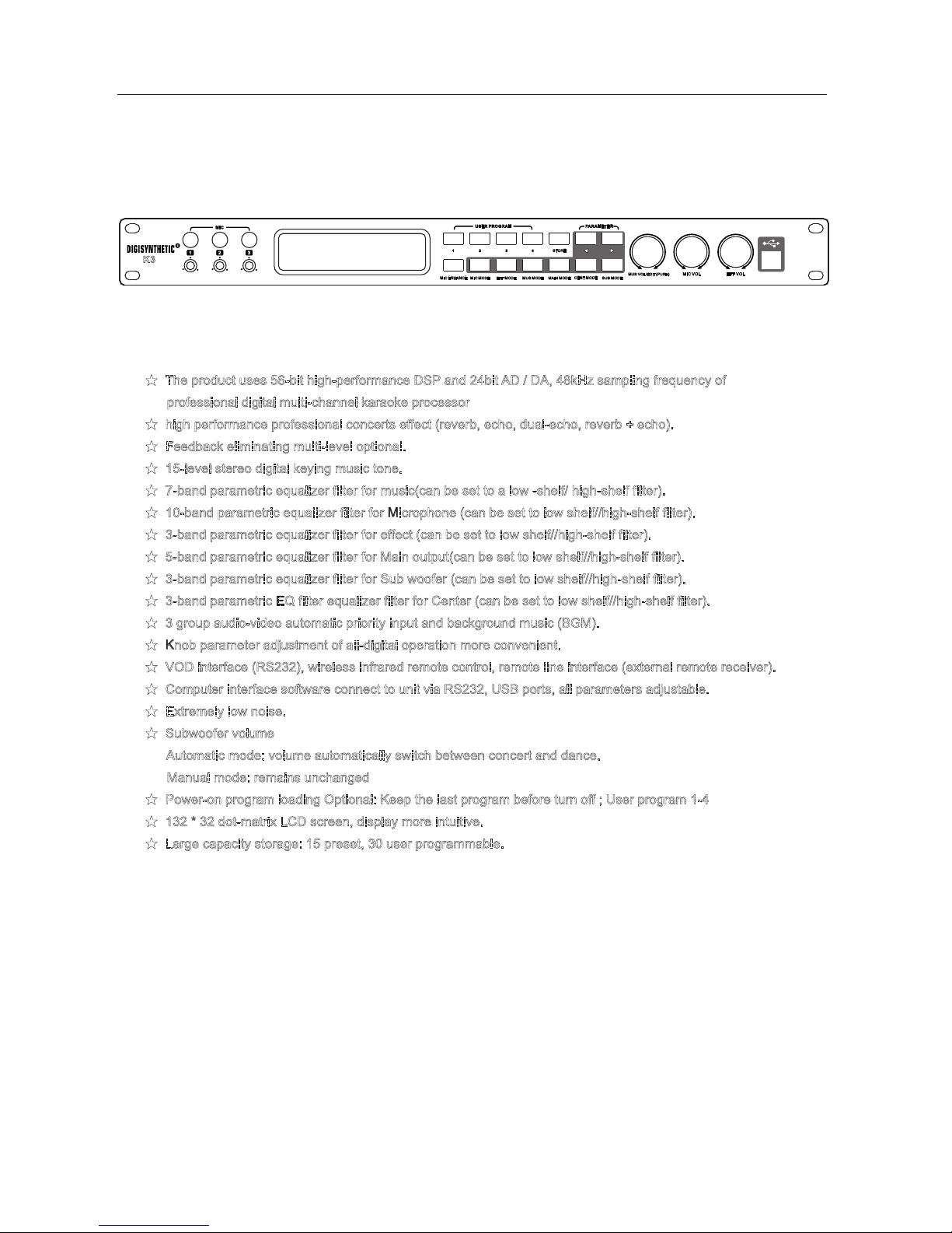
2、Product Overview
3
★
★
★
★
★
★
★
★
★
★
★
★
★
★
★
★
★
★
★
The product uses 56-bit high-performance DSP and 24bit AD / DA, 48kHz sampling frequency of
professional digital multi-channel karaoke processor
high performance professional concerts effect (reverb, echo, dual-echo, reverb + echo).
Feedback eliminating multi-level optional.
15-level stereo digital keying music tone.
7-band parametric equalizer filter for music(can be set to a low -shelf/ high-shelf filter).
10-band parametric equalizer filter for Microphone (can be set to low shelf//high-shelf filter).
3-band parametric equalizer filter for effect (can be set to low shelf//high-shelf filter).
5-band parametric equalizer filter for Main output(can be set to low shelf//high-shelf filter).
3-band parametric equalizer filter for Sub woofer (can be set to low shelf//high-shelf filter).
3-band parametric EQ filter equalizer filter for Center (can be set to low shelf//high-shelf filter).
3 group audio-video automatic priority input and background music (BGM).
Knob parameter adjustment of all-digital operation more convenient.
VOD interface (RS232), wireless infrared remote control, remote line interface (external remote receiver).
Computer interface software connect to unit via RS232, USB ports, all parameters adjustable.
Extremely low noise.
Subwoofer volume
Automatic mode: volume automatically switch between concert and dance.
Manual mode: remains unchanged
Power-on program loading Optional: Keep the last program before turn off ; User program 1-4
132 * 32 dot-matrix LCD screen, display more intuitive.
Large capacity storage: 15 preset, 30 user programmable.
1
USER PR OGRAM
PARAME TER
1 2
MIC ENHA NCE
MIC MODE
CENT MOD E
SUB MODE
3
4
STORE
MAIN MOD E
MUS MODE
EFF MODE
MUS VOL/ EDIT( PUSH)
EFF VOL
MIC VOL
MIC
2 3
K3

1
USER PR OGRAM
PARAME TER
1 2
MIC ENHA NCE
MIC MODE
CENT MOD E
SUB MODE
3
4
STORE
MAIN MOD E
MUS MODE
EFF MODE
MUS VOL/ EDIT( PUSH)
EFF VOL
MIC VOL
MIC
2 3
2
4
1
3
4
5 6
7 8 9 10 11 12 13 14 15 16 17
3、Front panel instruction
1 3-ways microphone input jack and volume control potentiometer
2 132 * 32 dot- matrix LCD display is used to display a variety of menus and parameter adjustment information.
3 Infrared remote control receiver window
4 User programming keys
5 Storage program key
6 Menu parameter switch key (in the start-up screen show the music rising tone, falling tone)
7 Microphone enhance keys
8 Microphone mode key
9 Effect mode key
10 Music mode key
11 Main output mode key
12 Center mode key
13 Subwoofer mode key
14 Music volume knob ("edit" function in the menu screen, adjust menu parameters, "ress " function is
switch other parameters in the same menu screen)
15 Microphone volume knob
16 effect volume knob
17 USB Connection
、
、
、
、
、
、
、
、
、
、
、
、
、
、
、
、
、
K3
5
1 2 3 4 6
789
10
11 12 13 14 15 16
17
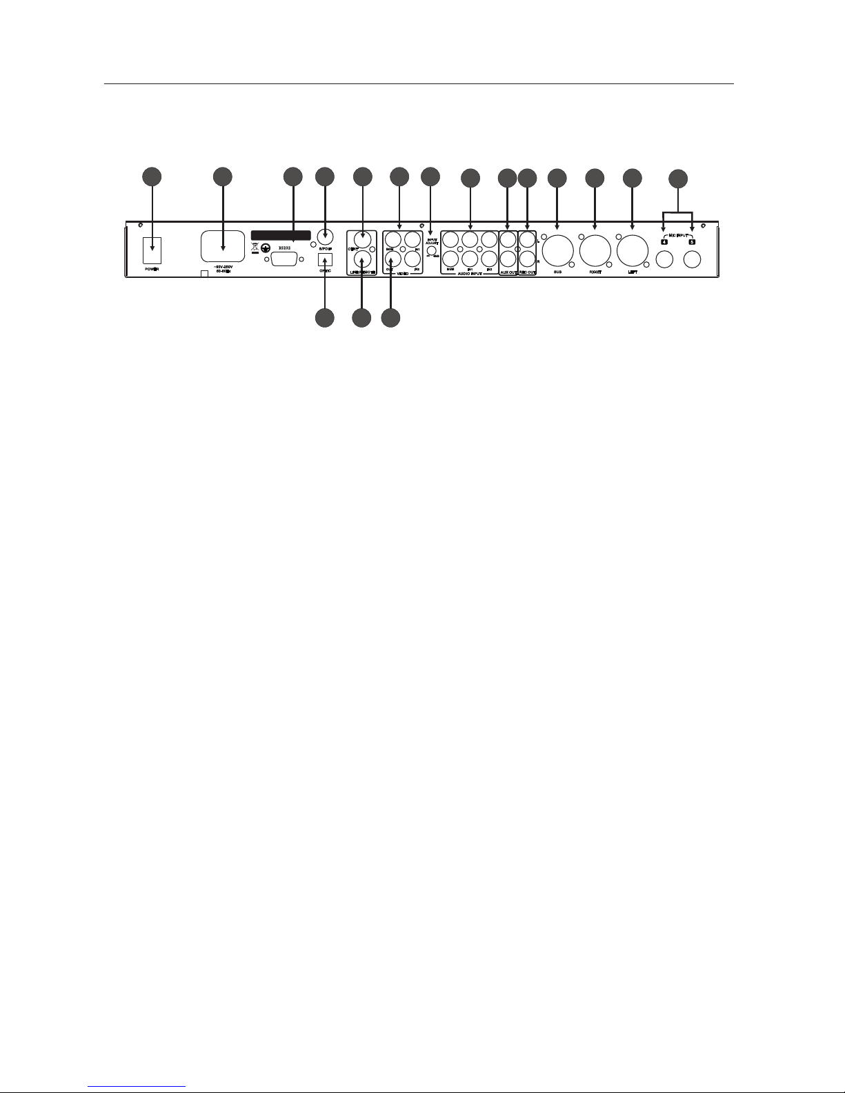
4、Rear Panel instruction
5
1 Power Switch (T1AL/250VAC)
2 Standard IEC Power Input (~ 90V-220V)
3 RS232 interface
4 Digital Audio Output (S / PDIF)
5 The OPTIC Interface (fiber interface)
6 Main Output
7 Remote Line Interface (external remote receiver)
8 3-way video inputs: the background music (BGM) "," Input 1 "," Input 2 "
9 1-way video output interface (selected from the 3-way input signal as the output signal)
10 Audio input level adjustment potentiometer
11 Stereo audio input interface: the background music (BGM) "," Input 1, Input 2
12 Auxiliary output (use as surround output)
13 Recording output
14 Sub woofer output
15 Right main output
16 Left main output
17 Microphone inputs
、
、
、
、
、
、
、
、
、
、
、
、
、
、
、
、
、
4 5
MIC INP UT
LEFTRIGHTS UB
L
R
REC OUT
AUX OUT
AUDIO I NPUT
IN2
BGM
IN1
-
∞
+3dB
INPUT
ADJUST
BGM
IN1
OUT
VIDEO
CENT
LINE RE MOTE
RS2 32
IN2
POWER
50-60 Hz
~90V-2 50V
S/PDI F
OPTIC
Mad e In Chin a
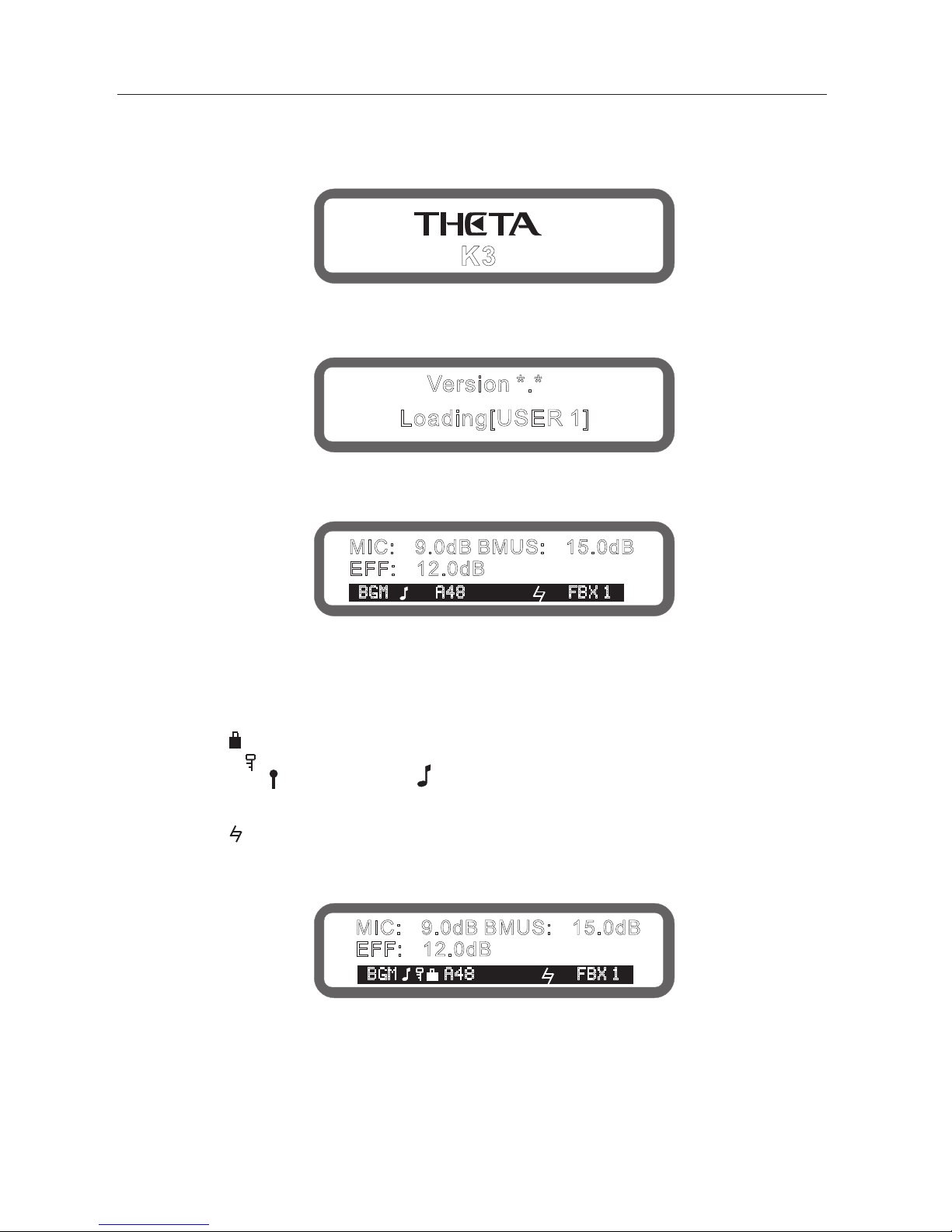
5、Power-On processor.
Connect power cable, press the power switch on the rear panel, screen display trademark will be shown as below:
Then the version No#, the processor unit starts loading data
(the boot loaded data can be set after the boot, there are 5 options:
[the last memory before turn-off], [1-4 user program],here show the selected set).
Loading is complete, display boot screen, as follows:
The boot screen shows the current microphone volume, music volume, effect volume
3-lines character and icon meaning is as follows:
The music input line (BGM/IN1/IN2)
Panel lock (" ", means the panel has been locked, no display indicates unlocked)
Encoder lock (" " means some parameters have been locked, no display indicates unlocked)
Subwoofer mode ( " " means concert mode," "means dance mode, no display indicates manual mode)
Musical input format ("A" represents the analog input "D" represents a digital input "44,48,32" represents
the sampling rate)
Music pitch (" " )
Feedback eliminator status ("FBX1-5" indicates feedback eliminate grade 1-5,
no display indicate feedback eliminator function closed)
6
Version *.*
Loading[USER 1]
MIC: 9.0dB BMUS: 15.0dB- -
EFF: 12.0dB-
BG M A48 F BX 1
BG M A48 F BX 1
MIC: 9.0dB BMUS: 15.0dB- -
EFF: 12.0dB-
K3
+
-
-
Mic
Mic
+
Musi c
Effe ct
Effe ct
-
+
Musi c
7
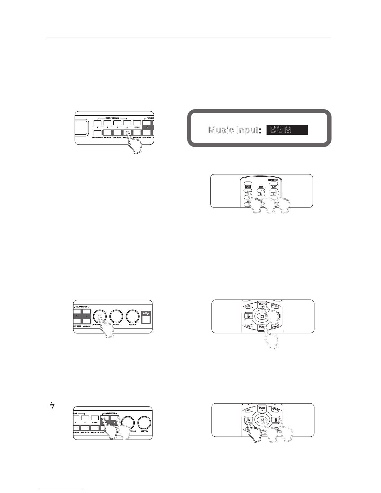
6、Music part operating instructions
6.1 Line select function of music input
6.1.1 analog music input
3-way analog music input line: background music, Input 1, Input 2
Potentiometer adjustment function, adjustment range: - 8 ~ +3 db
Method 1: continuously press panel buttons "music mode" until display to the music input selection screen,
as shown below:
Turning the knob "music volume/edited (pressed)" to set music input lines.
Method 2: setting from "device settings" of the interface software.
Method 3: use the remote control settings
6.1.2 digital audio format input (S /PDIF )
For different sampling rates (44.1khz/48khz) digital audio input, the machine will automatically recognize.
Method 1: Panel settings.
Method 2: setting from "device settings" of the interface software.
6.2 music volume set
Range: mute,-30db ~ 0db, Stepping: 0.5db
Method 1: panel knob usic volume set
Operation 2: on the remote control music + " Music-
Method 3: Operation from the interface software to set up
" "
" " "
BGM
4
IN2
IN1
2
1
5
PRES ET/US ER
3
6
FBE
Panel
Display
Music Input:
BGM
6.3 * Music tones
Range: b 7, b 6, b 5, b 4, b 3, B 2, B 1. # #1, #2, #3, #4, #5, #6 and #7
Method 1: The display on the screen.
Press the key on the panel " <" and " >" to set the music tone..
Method 2: remote control "b"
" ", "#"
REMOTE CONTROL
+
-
-
Mic
Mic
+
Musi c
Effe ct
Effe ct
-
+
Musi c
REMOTE CONTROL
Panel
REMOTE CONTROL
Panel
Method 3: Operation from the interface software to set up
+
-
-
Mic
Mic
+
Musi c
Effe ct
Effe ct
-
+
Musi c
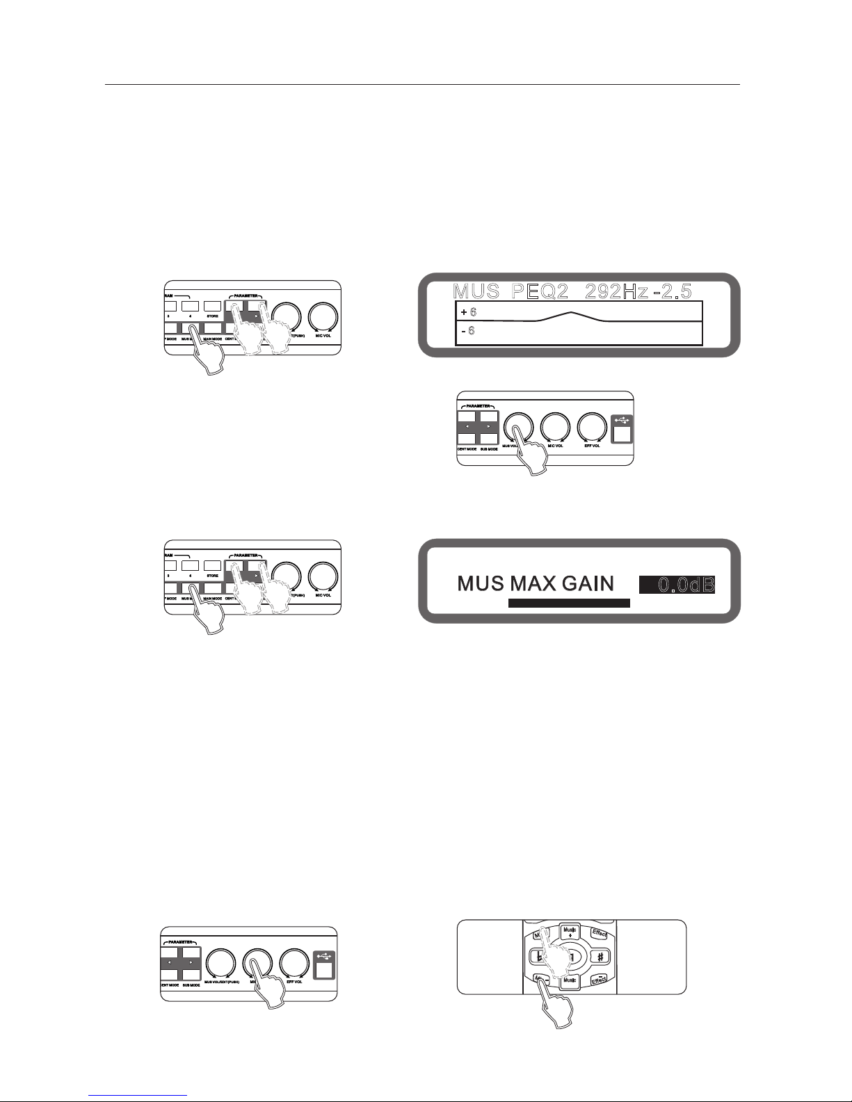
6.4. Music PEQ setting
PEQ: 7 bands
Type: Parametric equalization filters(can be set as low/high-tone filter), graphic equalization
(the 7 band can be set up as a high-cut).
Frequency range: 20Hz - 20kHz
Gain range: - 15db ~ + 12 db(can be limited to +6db in the "evice Settings" of interface software),stepping is 0.1 db
Band range: 0.011 ~3.595
Operating method 1: (panel can only set the gain) press "usic mode" on panel continuously to
enter the Music menu EQ,As below:
th
Press the " <" and " >" set the EQ
Rotate the knob " music volume/edit (press)" to set the gain "
Method 2: by the interface software
(All the EQ parameters can be set)
8
MUS PEQ2 292Hz -2.5
+ 6
- 6
Operation method 2: through the interface software to set up
6.6. Music Noise Gate settings
Scope: On and Off
Operation: Set up through the interface software.
7, Microphone part instructions
7.1microphone input and potentiometer settings
There are a total of 5 microphone connector, 3 on the front panel, 2 on rear panel.
3-microphone on the front panel with Level Adjust input, in general, set in the middle is best.
7.2 Microphone Volume Setting
Range: mute, -25dB~+6dB, stepping 0.5 dB
Operating method 1: panel knob Microphone volume set."
Method 2: Operation on the remote control icrophone + , microphone - "
Method 3: Operation from the interface software to set up
" "
" " "
6.5 The maximum volume setting
Range: mute,-30db ~ 0db, Stepping: 0.5db
Method 1: continuously press buttons "music mode" to the maximum music volume screen, as below:
MUS MAX GAIN
0.0dB
Panel
Display
Panel
Panel
Panel
REMOTE CONTROL
Display
6.7. Music low-Cut set
Range: OFF, 20Hz ~200Hz, stepping 5 Hz
Operation: Set up through the interface software.

BGM
4
IN2
IN1
2
1
5
PRES ET/US ER
3
6
FBE
9
7.3 Microphone Enhancement Feature
Range: adjust range - 50% (off) ~ + 50 %
Operating method 1: On the panel press the key "Music Enhance",
set to continuously change enhance switch, turn the knob to adjust music inspired.
Operating method 2: Operation from the interface software to set up
7.4 microphone optimization settings
Range: Off, Popular, Professional
Operation: Operation from the interface software to set up
7.6 microphone feedback elimination settings
Range: Off, Grade between 1 to 5.
Operation: Press panel button "microphone mode until show the
Feedback elimination on the screen, turning the knob "Music volume / Edit(Press) "to set the sensitivity
"
+ 8%
HPF: LPF:14.5kHz45Hz
OUT
MIC
MIC Enhance
FREQ
Panel
Display
Panel
REMOTE CONTROL
Panel
Panel
Display
7.5 microphone noise gate settings
Range: Off, On
Operation: Operation from the interface software to set up
Operating method 2: Operation from the interface software to set up
When the singer handheld microphone facing the speaker is singing, often occur howling/whistle,
the phenomenon often makes the listener feel irritable, serious cases will damage the speaker and amplifier.
Adjustment the feedback elimination setting, howling will be eliminated automatically, effective protection
of the speaker and amplifier.
Operation method 3: on the remote control "feedback inhibition" setting
7.7 microphone High-cut, Low-cut setting
Low-cut range: 20hz ~ 200hz, stepping 5hz
High-cut range: 12khz ~ 20khz, stepping 0.5khz
Operating Method 1: Press the panel button "microphone mode "into the microphone menu,
selected to the microphone low-cut, high-cut screen, as shown below:
Keys "<" and ">" switch Low-cut and High-cut.
Turning knob music volume / edit (press) " to set.
Operating method 2: Operation from the interface software to set up
"

10
7.8 microphone PEQ settings
Balanced qty: 10
Type: parametric equalization filter (can be set to low / treble tone filter), graphic equalizer
Frequency range: 20hz ~ 20khz
Gain Range:-15db ~ +12 db (can be limited to +6db settings, setting from Device Settings
in the interface software), step 0.1db
Bandwidth range: 0.011 to 3.595
operation: (panel only set the gain of equalizer election) Press the panel button microphone mode
until show MIC PEQ as below:
" "
" "
Buttons "<" and ">" to select the desired setting PEQ
Turning knob music volume / edit (press) to set the gain
Operating method 2: Operation from the interface software
to set up(all equalizer parameters can be set)
7.9 microphone direct sound volume, phase settings
Volume range: 0% ~100%, Stepping: 1%
Phase range: 0 180
Operation method 1: Press the panel button microphone mode " continuously into the microphone menu,
selected the direct sound and phase, as shown below:
° °
"
Keys "<" and ">" to switch direct sound and phase.
Turning knob "usic volume / edit (press) "to set
Operating method 2: Operation from the interface software to set up
MIC PEQ1 80.3Hz
+ 5.9
+ 6
- 6
100%
[0 ]
MIC DIR VOL
PHASE
Panel
Panel
Display
Panel
Panel
Display

11
7.10 effect volume set
Range: mute,-30db ~ 0db, Stepping: 0.5db
Operation: set by "effect volume knob on the panel.
Operating method 2: by effect +", ffect on the remote control
Operating method 3: Operation from the interface software to set up
"
" " "
Buttons "<" and ">" to select the desired setting PEQ
Turning knob music volume / edit (press) "to set the gain.
Operating method 2: Operation from the interface
software to set up(all equalization parameters can be set)
"
EFF PEQ 101Hz1
0.0
+ 6
- 6
Panel
+
-
-
Mic
Mic
+
Musi c
Effe ct
Effe ct
-
+
Musi c
REMOTE CONTROL
Panel
Display
Panel
7.11 Effect high-cut, low-cut set
Low-cut range: OFF, 50hz - 200hz, stepping 5hz
High-cut range: 8khz ~ 16khz, OFF, stepping 0.5khz
Operating : Operation from the interface software to set up
7.12 Effect PEQ set
The PEQ qty: 3
Type: parametric equalization filter (can be set to low / treble tone filter), graphic equalizer
Frequency range: 20hz ~ 20khz
Gain Range:-15db ~ +12 db, step 0.1db
Bandwidth range: 0.011 to 3.595
Operation: (panel only set the gain of equalizer )
Press the panel button Effect Mode until show EFF PEQ as below:
" "

12
7.13 Echo volume, phase settings
Volume range: mute,-30db ~ 0db, Stepping: 0.5db
Phase range: 0 , 180
operation: Press the buttons "Effect Mode" on the panel continuously into the echo volume and phase screen,
as shown below:
Buttons "<" and ">" to switch Echo volume and phase
Turning knob "music volume / edit (press) "to set .
Operating method 2: Operation from the interface
software to set up
7.14 Echo delay set
Delay range: 100ms-600ms, stepper: 5ms "
Depth range: 0% -100%, Stepping: 1%:
Operation: Press the buttons "Effect Mode" on the panel continuously into the effect delay, as shown below:
Button "<", ">" Switching echo delay and depth.
Turning knob "music volume / edit (press) "to set
Operating method 2: Operation from the interface software to set up
7.15 Effect maximum volume setting
Range: mute,-30db ~ 0db, Stepping: 0.5db
Operation: Press the buttons "Effect Mode" on the panel continuously into the effect maximum volume, as shown below:
Turning knob "music volume / edit (press) "to set the maximum volume.
Operating method 2: Operation from the interface software to set up
° °
ECHO DELAY 200ms
ECHO DEPTH 60%
10.0dB-
[0 ]
EFF MAX VOL 0.0dB
Panel
Display
ECHO VOL
PHASE
Panel
Panel
Display
Panel
Panel
Display
Panel

13
ECHO MODE
MONO
ECHO TO REV OFF
7.16 Echo mode, Echo thickness settings
Range: Single, stereo, dual echo
Range: On, Off
Operation: Press the buttons "Effect Mode" on the panel continuously into the Echo Mode/ Echo Thickness,
as shown below:
Keys "<" and ">" Switch echo pattern and thickness.
Turning knob "music volume / edit (press) "to set
Operating method 2: operation from the interface software to set up
7.17 Reverb volume, phase settings
Volume range: mute,-30db ~ 0db, Stepping: 0.5db
Phase range: 0 , 180
Operation: Press the buttons "Effect Mode" on the panel continuously into the Reverb
Volume/ Phase, as shown below:
Keys "<" and ">" switch reverb volume and phase.
Turning knob "music volume / edit (press) "to set
Operating method 2: Operation from the interface software to set up
7.18 reverb pre-delay, reverb-time setting
Reverb pre-delay range :0-250ms, Stepping: 10ms
Reverb-time range :0.5-6s, Stepping: 0.1s
Operation: Press the buttons "Effect Mode" on the panel continuously into the Reverb
Pre-delay/ Reverb-time, as shown below
Keys "<" and ">" switch reverb pre-delay and reverb-Time.
Turning knob "music volume / edit (press) "to set
Operating method 2: Operation from the interface software to set up
:
° °
REV PRE-DELAY 0ms
REV TIME 3.2s
Panel
Display
Panel
Panel
10.0dB-
[0 ]
Display
REV VOL
PHASE
Panel
Panel
Panel
Display

14
7.19 reverb type set
Range: 1.off ; 2. Room ; 3 Small hall; 4.Hall; 5. Church; 6. Cathedral; 7. Vocal.
Operation: Press the buttons "Effect Mode" on the panel continuously into the Reverb Type, as shown below:
Turning knob "music volume / Edit (press)" to set the reverb type
Operating method 2: Operation from the interface software to set up
REV TYPE
Room
8、the main output section instructions
8.1 main output volume, balance setting
Range: mute,-30db ~ 0db, Stepping: 0.5db
Operation: Press the buttons "Main output Mode" on the panel continuously into the Main output volume and
main output balance, as shown below:
Keys "<" and ">" to switch the main output volume and main
output balance.
Turning knob "music volume / edit (press) "to set
Operating method 2: Press keys "balance + " and" balance - "
on the remote control.
Operating method 3: Operation from the interface software to set up
MAIN OUT VOL 0.0dB
MAIN BALANCE L R 100%
Panel
Display
Panel
Panel
Display
Panel
REM OTE CON TROL
SUB BAL
CENT
+
SUB
CENT
-
BAL
+
-
+
REMOTE CONTROL

15
MIC DIR TO MAIN -5.0dB
EFF TO MAIN
MUS TO MAIN: 0.0dB
8.2 Direct sound to the main output, and the effect to the main output volume setting
Range: Mute,-30db ~ 0db, Stepping: 0.5db
Operation: Press the buttons "Main output Mode" on the panel continuously into the Direct sound to main output and
Effect to the main output volume, as shown below:
Keys "<" and ">" to switch the needed parameters.
Turning knob "music volume / edit (press) "to set
Operating method 2: Operation from the interface software to set up
8.3 Music to the main output volume settings
Range: Mute,-30db ~ 0db, Stepping: 0.5db
Operation: Press the buttons "Main output Mode" on the panel continuously into the Music to main output volume,
as shown below:
Turning knob " usic volume / edit (press) "to set
Operating method 2: Operation from the interface software to set up
8.4 main output PEQ settings
The PEQ qty: 5
Type: parametric equalization filter (can be set to low / treble tone filter) and graphic equalizer
Frequency range: 20hz ~ 20khz
Gain Range:-15db ~ +12 db, step 0.1db
Bandwidth range: 0.011 to 3.595
Methods of operation: (panel can only set the equalizer gain)Press the buttons "Main output Mode" on the panel
continuously into the MAIN PEQ, as shown below:
As shown below:
MAIN PEQ 101Hz1
0.0
+ 6
- 6
Panel
Panel
Panel
Panel
0.0dB
Display
Display
Display

16
Keys "<" and ">" to switch the needed PEQ.
Turning knob "music volume / edit (press) "to set Gain.
Operating method 2: Operation from the interface software to
set up(all equalizer parameter can be set )
8.5 Main output left delay, right-delay setting
Range: 0.0ms ~ 5.0ms, stepping 0.1ms
Operation method1: Press the buttons "Main output Mode" on the panel continuously into the Main output delay,
turning knob "usic volume / edit (press) "to set.
Operating method 2: Operation from the interface software to set up
8.6 Main output compression settings
Threshold range: -20 ~ +16 db, stepping 0.5db
Ratio: 2:1 4:1 8:1 16:1 32:1 64:1 128:1
Range: On, Off
Operation method1: (Only can set Threshold range and Ratio)Press the buttons "Main output Mode" on the panel
continuously into the Main output compression, as shown below:
Keys "<" and ">" to switch the Threshold Rang and Ratio.
Turning knob " usic volume / edit (press) "to set.
Operating method 2: Operation from the interface software to set up
MUS COMP:
THRES RATIO
2:1
-7 .0d B
OUT
In
+16
-20
Panel
Panel
Display
Panel

17
9.1 Center volume setting
Range: Mute, -3
0db ~ 0db, Stepping: 0.5db
Operation method 1: Press the buttons "Center Mode" on the panel continuously into the Center volume , as shown below:
Keys "<" and ">" to switch the center volume and microphone maximum volume.
Turning knob"usic volume / edit (press) "to set.
Operating method 2: Press on the keys "Center +" and ?Center -" on the remote control.
Operating method 3: Operation from the interface software to set up
9.2 Direct sound to the center, Effect to the center volume setting
Range: mute,-30db ~ 0db, Stepping: 0.5db
Operation method 1: Press the buttons "Mic Mode" on the panel continuously into the Direct sound to Center
and Effect to center , as shown below:
Keys "<" and ">" to switch Direct sound to the center and Effect to the center.
Turning knob "usic volume / edit (press) "to set.
Operating method 2: Operation from the interface software to set up
9.3 Center music delay, and The music to center volume set
Center Music delay range: 0 ~ 5ms, stepping 0.5ms
Music to the Center volume range: Mute,-30db ~ 0db, Stepping: 0.5db
How: Press the panel button microphone mode "election to set to music the delay, the volume of the music to the
center screen, as shown below:
Operation method 1: Press the buttons "Mic Mode" on the panel continuously into the Center music delay and
Music to the Center volume , as shown below:
9、Center part operating instructions
CENT VOL
0.0dB
CENT MAX VOL
+ 6.0dB
MIC DIR TO CENT -5.0dB
EFF TO CENT MUTE
CENT DELAY: 0.0ms
MUS TO CENT: 0.0dB
Panel
Display
Panel
REM OTE CON TROL
SUB BAL
CENT
+
SUB
CENT
-
BAL
+
-
+
REMOTE CONTROL
Panel
Display
Panel
Panel
Display

Keys "<" and ">" to switch Direct sound to the center and Effect to the center.
Turning knob "usic volume / edit (press) "to set.
Operating method 2: Operation from the interface software to set up
9.4 Center PEQ settings
The PEQ qty: 3
Type: parametric equalization filter (can be set to low / treble tone filter) and graphic equalizer.
Frequency range: 20hz ~ 20khz
Gain Range:-15db ~ +12 db, step 0.1db
Bandwidth range: 0.011 to 3.595
Operation method1: (Only can set EQ gain on the panel)Press the buttons "Mic Mode" on the panel continuously
into the CENT PEQ, as shown below:
Keys "<" and ">" to select the needing PEQ
Turning knob "usic volume / edit (press) "to set gain
.
Operating method 2: Operation from the interface software to set up
9.5 High-cut, low-cut settings
Low-cut range: OFF, 20Hz ~ 300Hz, stepping 5Hz
High-cut range: 2.5kHz ~ 20kHz, OFF, stepping 0.5khz
Operating method : Operation from the interface software to set up
18
CENT PEQ 101Hz1
0.0
+ 6
- 6
Panel
Panel
Display
Panel

10.1 Sub woofer volume and phase settings
Volume range: mute,-30db ~ 0db, Stepping: 0.5db
Phase range: 0 , 180
Operation method 1: Press the buttons "Sub Woofer Mode" on the panel continuously into the Sub woofer volume and
phase, as shown below:
Keys "<" and ">" to switch the Sub woofer volume and phase
Turning knob "music volume / edit (press) "to set
Operation method 2: Press the keys "bass +" and "bass" on the remote control
Operating method 3: Operation from the interface software to set up
10.2 High-cut, Low-cut setting
Low-cut range: 19.7 ~ 1000hz,, 203 stepper
High-cut range: 35.1 ~ 2000hz, 209 stepper
Operation method 1: Press the buttons "Sub Woofer Mode" on the panel continuously into the Low-cut and High-cut,
as shown below:
Keys "<" and ">" to switch the High-cut and Low cut
Turning knob "music volume / edit (press) "to set
Operating method 2: Operation from the interface software to set up
° °
10、The Sub woofer part operating instructions
19
SUB VOL
-19.5dB
PHASE
[0 ]
HPF: 19.7Hz LPF:2000Hz
OUT
SUB
Panel
REM OTE CON TROL
SUB BAL
CENT
+
SUB
CENT
-
BAL
+
-
+
REMOTE CONTROL
Display
Panel
Display
FREQ
Panel
Panel

10.3 Sub woofer PEQ settings
PEQ qty : 3
Type: parametric equalization filter (can be set to low / treble tone filter) and graphic equalizer
Frequency range: 20hz ~ 20khz
Gain Range:-15db ~ +12 db, stepping 0.1db
Bandwidth range: 0.011 to 3.595
Operation method 1: (Only can set EQ gain on the panel)Press the buttons "Sub Woofer Mode" on the panel
continuously into the SUB PEQ, as shown below:
Keys "<" and ">" to select the needing PEQ
Turning knob "music volume / edit (press) "to set gain
Operating method 2: Operation from the interface software to set up
(all the parameter of EQ can be set)
10.4 Subwoofer music delay, direct sound to the Subwoofer volume settings
Subwoofer music delay range: 0 ~ 20ms, stepping 0.5ms
Direct sound to the subwoofer range: MUTE,-30db ~ 0db, Stepping: 0.5db
Operation method 1: Press the buttons "MIC Mode" on the panel continuously into the Subwoofer music delay and
Direct sound to the subwoofer volume, as shown below:
Keys "<" and ">" to switch Subwoofer music delay and Direct sound to subwoofer volume
Turning knob "music volume / edit (press) "to set gain
Operating method 2: Operation from the interface software to set up
20
SUB PEQ3 120Hz
+ 10.0
+ 6
- 6
SUB MUS DELAY: 0.0ms
MIC DIR TO SUB: 0.0dB
Panel
Display
Panel
Panel
Panel
Display

10.5 Subwoofer compressor settings
Threshold range: -20 ~ +16 db, stepping 0.5db
Ratio: 2:1 4:1 8:1 16:1 32:1 64:1 128:1
Range: On, Off
Operation method 1: (Only Threshold can be set )Press the buttons "Sub Mode" on the panel continuously into the
Subwoofer compressor, as shown below:
Turning knob "music volume / edit (press) "to set Threshold
Operating method 2: Operation from the interface software to set up
The processor unit provides 15-preset programs and 30-user programs.
1 1.1 Program saved
Operation method 1: Press the keys "Save" on the panel, as below:
Turning knob "music volume / edit (press) "to choose the program to save .
Press the key " ave? again to save the program.
Operating method 2: Operation from the interface software to set up
11.2 program recall
Operating method 1: Press the keys[1], [2],[3], [4]: recall the program directly.
Operating method 2: by remote control
Operating method 3: Operation from the interface software to set up
11、Program/Memories management functions
21
SUB COMP:
THRES:
-9 .0d B
OUT
In
+16
-20
Save To
1
User Memory ?
Panel
Display
Panel
Panel
Display
Panel
Panel
BGM
4
7
IN2
IN1
2
1
5
8
3
6
9
0/30
10+ 20 +
REMOTE CONTROL

12 、Turn-On to load the selected program.
22
11.3 program deleted (computer software interface features)
11.4 program data is saved to the computer (computer software interface features)
11.5 program import the data from the computer to the processor (computer software interface features)
Connect the Processor unit to the computer ,open the software, set the program in"eboot effect"rom "evice setting"
(Program 1-4; Last program status before turn off).
The default program will be one of 1-4 whether or not making any parameter
adjustment before reboot. This feature is to prevent extra work loaded applied to the
Musical Technicians.
Default program remain the same to prevent sudden power failure.
Progr ams(memor ie s)
1 4-
Last program
13 Volume, Maximum gain limit functions
14 volume fader function
Set through the online software interface with the computer: "Device Settings"
Maximum volume of the music: Mute,-30db ~ 0db, Stepping: 0.5db
Maximum volume of the microphone: Mute,-25db ~ +6 db, Stepping: 0.5db
Maximum volume of effect: mute,-30db ~ 0db, Stepping: 0.5db
Maximum volume of center: mute,-30db to 0db stepper: 0.5db
Maximum volume of subwoofer: Mute,-30db ~ 0db, Stepping: 0.5db
The maximum gain of music equalizer : +6.0 db to +12.0 db, Stepping: 0.1db
Volume limit feature: To protect and prevent damaging speakers and amplifier in a certain range.
To avoid setting too high volume destroyed the sound field. Example: When the microphone parameter is set to-10db,
then the upper limit value of microphone volume is-10db, when using the microphone volume knob or the remote control
to adjust the microphone volume, maximum output volume is -10db.
Set this function under "Device Settings" in the software provided.
If the Switching Speed of its parameters set to fade during power On/off, Recall program, conversion mode,
the signal line, the signal is from small to large incremental increase; If the parameter set to "immediately",
the signal is changed over directly without fading process.
、
、
" "

23
Reset.....
Panel
Display
15、Subwoofer output options.
16、music pitch automatic recovery function
17、panel lock, parameter lock function
18、power-on reset function
19、boot screen automatically returns
20、 Language selection function
Set this function under "Device Settings" in the software provided.
when the mode is manual, the subwoofer volume setting does not change.
when the mode is automatic: once the Microphone receives input signal, subwoofer output volume is the "concert" setting.
if Microphone has no input signal, a certain time later , the subwoofer volume will switch to "ance" settings automatically .
The following parameters are valid only in the automatic mode: concert volume, dance volume
The microphone detection threshold: When the microphone detects a level greater than this threshold, then determinate
the microphone has input; otherwise determined to be no input.
The microphone detects time: when microphone no-signal input time more than this time, the subwoofer output volume
will switch to "Dance" volume setting automatically.
The music pitch will adjust treble or bass when the user failed to meet the correct tone.
It will return to original musical setting after it.
17.1 panel lock function
Press the knob [music volume / edit (press)] more than 5 seconds to lock the system
Press the Knob [Music volume / Edit (press)] for more than 5 seconds to unlock the system.
17.2 parameter lock function
Operation from the interface software to set up
Reboot while holding down the keys main output Mode and usic Mode until the display shows as follows
Note: After the reset, the user program will be deleted! Please stored in the computer in advance!
System will return to Start-Up screen automatically when no operation in 180s.
To change system language, press [Center Mode] and [Bass Mode] same time.
" " " "

21、 the wireless remote control
The easy-to-use remote control function, eliminating the need for manual operation. Simple parameter adjustment makes
you to adjust the parameter settings used easily as picture shown below. :
Remote con trol keys fu nction
Sheet 1 (the remote cont rol code, da ta-digit hexadecimal)
Adjust th e fe edback el im ination
Feedback eliminate
Digit keys
BGM(background music)
Input 1 Input 2
、
、
" "" " "
" " " "
0/30 1~ 9
10+ 20+
Press dig it k eys 1 ~ 9 can r ec all the mem or ies 1 ~ 9 ;
Press the " 10 + " firstly, w ithin 3 sec on ds press "0 " ~ "9 "
can recal l th e memorie s 10 ~ 1 9
Press the 0 +" f irstly, within 3 se co nds press " 0" ~ " 9"
can recal l th e memorie s 20 ~ 2 99
Press key 0/30 c an recall t he m emory 0 d ir ectly.
" "" " " " " " "
"
" " " "
Adjust th e mu sic input l in e
Press the d ig it keys to re ca ll the memo ry d irectly
Keys
Function
Code CodeCode Code
Keys KeysKeys Keys
24
MIC+ MIC-、
MUSIC+ MUSIC-、
EFFECT+ EFFECT-、
Demote Tone Original
Tone Rise Tone
、
、
SUB+ SUB-、
Cent+ Cent-、
EQ+ EQ-、
Feedback Eliminate
Default / user
Background Music(BGM)
Input 1
Output 2
1
2
3
4
00
01
04
03
02
05
06
07
0A
5
6
7
8
9
0/30
10+
20+
MIC+
09
08
0B
0C
0D
10
0F
0E
11
MIC -
Music+
Music-
Effect+
Effect-
Reduce Tone
Original Tone
Rise Tone
SUB+
17
12
18
13
19
16
15
14
1B
SUB-
Center +
Center -
EQ+
EQ-
1D
1E
1F
1A
1C
21.1 line remote function
This function is an external remote control receiver. Line remote interface defines the following figure:
5V Power Ou tp ut
Ground
Line Remo te C onnect( pr ocessor r ea r panel soc ke t)
Line remo te c ontrol
signal in pu t
RE MOTE C ON TRO L
BGM
4
7
IN2
IN1
2
1
5
8
+
-
SUB BAL
CEN T
+
SUB
CEN T
-
BAL
PRE SET/U SER
-
MIC
MIC
+
MUS IC
EFFE CT
EFFE CT
3
6
9
-
+
-
+
+
FBX
0/3 0
10+ 2 0+
MUS IC
Microphone volume Adjust
Music volume Adjust
Effect volume Adjust
Music Tone Adjust
SUB volume Adjust
Center volume Adjust
Main Left/Right output volume Adjust

25
22、When on-line computer interface software control the processor
functions Online, the panel can not operate.
23、Important instruction on PC control
COM Port Detect Automatically.
Software can set all the parameters of the processor.
Please refer to the corresponding HELP documentation software instruction.
USB and RS232 cannot operate together. If RS232 interface is needed, please remove USB connection.
Please read the following instruction carefully before doing the connection.
Or there is more risks on abnormal conditions as offline, computer crash.
Please assure the AC power applies with the machine working condition.
The ground connection should be set with AC power.
Please use the AC power to connect the computer with the machine.
Do not install the control software with the same version and model repeatedly.
Do not load all the software in the same catalogue. Advise to set the separate file folder for saving the software.
Try to avoid doing the PC software control operation in the condition with strong signal interference.
The wrong operation will lead to fail controlling and even damage the machine and the computer.
a.Do not insert or pull out the connection interface at the power on condition before PC connection..
b.Do not move the computer, the machine and the connecting cable after PC connection.
c.Do not use the panel operation or touch the key on the panel after PC connection.
d.Do not insert or pull out the connection interface of the computer and the machine after successful
PC connection.
E.Do not use one computer to control several machines.
Please refer to IMPORTANT SAFETY INSTRUCTION in the user instruction.
⑴
⑵
⑶
⑷
⑸
⑹
⑺
GROUN DING
24 Accessorie s:
Accessor ies Qty
RS232 Computer Communication lines
Software CD
USB computer communication line
Manual
Remote Control
1
1
1
1
1
Computer Iterface AC Power

26
25、Technical Specification
Music parts
SNR >102dB(BYPASS , Pitch shift closed)
THD 0.01% 20Hz-20kHz
Frequency response 20Hz-20kHz ± 0.5dB
Input sensitivity/ impedance 0.707V/47kohm
Max-output 14Vpp/60ohm EQ output
Parametric EQ :5 bands
Type PEQ High-shelf Low-shelf、 、
Gain +12dB~-15dB Stepping, ± 0.1dB
Frequency: 20Hz~20kHz
Bandwidth: 0.011-3.595
Pitch Shift ± 7 Levels, Stepping 100 cents
Stereo audio input Level-adjustment - ~+0dB∞
Video:
3-way video input, 1-way video output
Input Sensitivity/Impedance 1Vpp/75ohm
Output Sensitivity/Impedance 1Vpp/75ohm
Sub woofer parts
THD 0.01% 20Hz-2000Hz
Frequency Response 20Hz-2000Hz ± 0.5dB
3-bands PEQ
Type PEQ High-shelf Low-shelf、 、
Gain +12dB~-15dB Stepping 0.1dB, ±
Frequency 20Hz~2000Hz
Bandwidth 0.011-3.595
MIC parts
SNR >100dB(Effect closed)
THD
0.01%
50Hz-16kHz(Effect closed)
Frequency
Response
50Hz-16kHz ± 0.5dB
42mv/4.7kohmInput sensitivity/ impedance
Max-output 13.8Vpp
7-bands PEQ
Type PEQ High-shelf Low-shelf、 、
Gain +12dB~-15dB step 0.1dB, ±
Frequency 20Hz~20kHz
Bandwidth 0.011-3.595
5-way MIC input
Remote 1-way line control 5-pin, socket
RS232 9-pin socket
USB
Power Voltage AC 90-250V/50Hz
Fuse T1AL/250VAC
Power-consumption 10W
Weight 2.2KG
Size 45 482 123(mm)× ×
 Loading...