

USER MANUAL
POWER
EXCELLENT POWER AMPLIFIER
DIGISYNTHETIC
R
DP4800
DP3200
DP2240
DP1800
DP1400
CLIP
SIGNAL
PROTECT
Channel A Channel B
DP Series
Power Amplifier
PROPRO
CLIPCLIP
BRIDGEBRIDGE
ONON
CH CCH C
CH DCH DCH ACH A
CH BCH B
DP 4800
-4
-18
-21
-14
-24
-8
-28
-36
-2
0
-¡Þ
-18
-21
-14
-24
-8
-28
-36
-2
0
-¡Þ
-18
-21
-14
-24
-8
-28
-36
-2
0
-¡Þ
-18
-21
-14
-24
-8
-28
-36
-2
0
-¡Þ
PROTECT
SIG/CLIP
BRIDGE
PROTECT
SIG/CLIP
BRIDGE
DP 3200

WARNING
When using electric products, basic precautions should always be followed:
1. Read all the SAFETY INSTRUCTIONS before using the product.
2. This product must be earthed. If it has malfunction or breaks down, grounding provides a path of
least resistance for electric current to reduce risk of electric shock.
This product is equipped with a cord having an equipment-grounding conductor and a grounding plug.
The plug must be plugged into an appropriate outlet that is properly installed and earthed in accordance
with all local codes and ordinance.
DANGER - Improper connection of the equipment-grounding conductor can result in a risk of
electric shock. Check with a qualified electrician or serviceman if you are in doubt as to whether the
product is properly grounded. Do not modify the plug provided with the product - if it will not fit the outlet,
have a proper outlet installed by a qualified electrician.
3. To reduce the risk of injury, close supervision is necessary when the product is used near children.
4. Do not use this product near water - for example, near a bathtub, washbowl, kitchen sink, in wet
basement or near a swimming pool or the lake.
5. This product may be capable of producing sound levels that could cause permanent hearing loss.
Do not operate for a long period of time at high volume level or at a level that is uncomfortable. If you
experience any hearing loss or ringing in the ears, you should consult an audiologist.
6. This product should be located so that its location or position does not interfere with its proper
ventilation.
7. This product should be located away from heat sources such as radiators, heat registers or other
products that produce heat.
8. The product should be connected to a power supply only of the type described on the operating
instructions or as marked on the product.
9. This product may be equipped with a polarized line plug (one blade wider than the other). This is a
safety feature. If you are unable to insert the plug into the outlet, contact an electrician to replace your
obsolete outlet. Do not defeat the safety purpose of the plug.
10. The power-supply cord of the product should be unplugged from the outlet when left unused for a
long period of time. When unplugging the power-supply cord, do not pull on the cord, but grasp it by
the plug.
11. Care should be taken so that object do not fall and liquid are not spilled into the enclosure through
openings
12. The product should be serviced by qualified service personnel when:
A. The power-supply cord or the plug has been damaged;
B. Objects have fallen, or liquid has been spilled into the product;
C. The product has been exposed to rain;
D. The product does not appear to operate normally or exhibits a marked change in performance;
E. The product has been dropped or the enclosure damaged.
13. Do not attempt to service the product beyond that described in the user-maintenance instructions.
All other servicing should be referred to qualified service personnel.
WARNING - Do not place objects on the product's power cord or place it in a position where
anyone could trip over, walk on or roll anything over it. Do not allow the product to rest on or to be installed
over power cords of any type. Improper installations of this type create the possibility of fire hazard and/
or personal injury.
IMPORTANT SAFETY INSTRUCTION
1

Installation & operating instruction
Mains power connection.
Before connecting the amplifier to the mains power socket, make certain that the voltage corresponds
with that indicated on the rear of the unit (an allowance of ¡À 10% is acceptable).
Before connecting the power cable to the mains, always make certain that it is not damaged
and that there are no bare wires, always connect the power cable to the amplifier before
switching it on and only remove the cable after switching it off.
Switching on and off.
In an audio system, it's always better to switch power amplifiers on last and off first.
Remember to switch off the amplifier before connecting it to or disconnecting it from other units
and to switch always on first the mixer and then the amplifier: in this manner, peaks which are
annoying and sometimes dangerous particularly for the loudspeakers enclosures are avoided.
It is normal for the LEDs to light up for a few moments when switching on.
Handling.
Do not force knobs and connectors, as they could be damaged if treated with excessive
force.
Connections and prevention of possible interference.
Avoid installing your equipment near radios, televisions, etc., since they could cause noisy
disturbance. When connecting the other units in your sound system, watch out for to so-called
earth-loops, which can cause hum: in the event of interference, try using the EARTH switch on
the amplifier's rear panel.
Connector cables.
To connect the amplifier to the mixer, always make certain to use only signal cables
(screened cables made up of two wires plus a braid screen), not power cables (speaker
cables, normally made up of two wires, usually with a greater cross-section): to connect the
amplifier to the loudspeaker enclosures, always use power cables, not signal cables, as in the
latter case in fact, the power from the amplifiers would be partially disperse because of the
cable's smaller cross-section.
Take care of the connector cables. Always hold them by the connectors, avoiding pulling the
wire and avoid knots and twists when coiling them: this gives the advantage of increasing their
life and reliability.
Air circulation for cooling.
Amplifier's correct cooling is ensured by an internal fan, the speed of which is controlled by a
special sensor (the speed is proportional to output power and therefore the temperature
generated):remember never to block the air vents located on the unit's sides in any way: the air
necessary for cooling passes through these.
If the amplifier is kept in a flight-case during use, make certain that it has sufficient openings at
both the amplifier's air vents. Avoid locating it very small spaces which don't allow correct air
circulation.
2

FEATURE
1. Perfect electronic protections: short circuit/overload protection, overheating
¡¡protection and direct current excursion protection.
2 .Low noise and lower distortion
3. Three output modes: stereo, mono and bridge(only for DP1400 and Dp4800)
4. THD+N: 0.08%@1kHz
5. Frequence response: 20Hz-20kHz
3

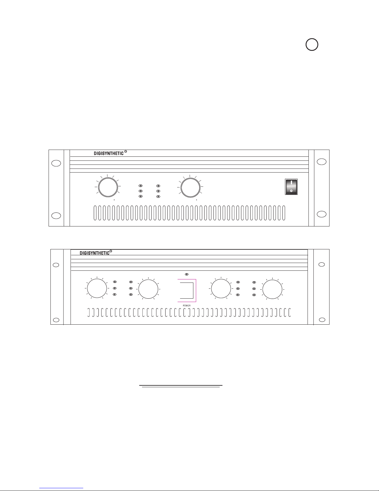
CONTROL PANEL
FRONT PANELA.
1
5
4
3
22
6
1. POWER: ON/OFF switch
2. CHA\B LEVEL : Adjust the volume of four channels
Control of the input level of the external signal: operates with continual
values which vary from £¢fully closed (position £¢-¡Þ£¢-the signal is not
fed to the amplifier sections) to fully open (position 0dB -the signal is
sent to the amplifier sections at the same level as that with which it arrives
at the input). In other words, this control operates s an attenuator of the
"
""""
3. PROTECT LEDs
Protection pilot lights.
If these LEDs light up, this indicates that one of the various protections
safeguarding the different sections of the amplifier and the loudspeaker
Enclosures has tripped due to an operating fault. In these cases, the
power output is normally switched off until normal operating conditions
are restored.
The following is a description of all the protections:
1) THERMAL PROTECTION ON TRANSISTOR: this protection intervene
whenever there is an excessive rise in temperature of the internal
heatsink.
4
POWER
CLIP
SIGNAL
PROTECT
Channel¡¤A Channel¡¤B
DP 3200

2)VOLTAGE PROTECTION: trips in the event of a short-circuit or
overload, limiting the output current.
3)CIRCUIT DAMAGE PROTECTION: in the events of damage, limit the
damage to extend, minish the loss.
Some protection situations require the amplifier to be switched off and
then back on for normal operating conditions be restored.
i
4. LIMIT LEDS
Amplifier £¢status indicators: these LEDs are able indicating the
operation of the internal limiter, when inserted, or the clipping of the
amplifier. They are POST-LEVEL: in other words they display the status of
"
5. SIGNAL LEDs
Signal status indicators: able to indicate a signal presence in the inputs
of the amplifier.
""
6. BRIDGE LEDS (only for DP1400 and DP4800)
Bridge switch with yellow indication. Pull the switch to the position
RIDGE , it lights up; Pull the switch to the position STEREO , it lights
off.
"B " " "
The bridge position:
5

8
B. REAR PANEL
11
6

8. OUTPUTS
Power out : outputs to be connected to the loudspeaker enclosures. Amplifier's A&B outputs
both have BINDING-POST connectors and speaker connectors
Only loudspeaker(or loudspeaker enclosure systems)within the amplifier's
declared power and Impedance load range should be connected to the
amplifier's outputs (see Technical pecifications). Use only speaker cables
(two-core cables, normally with a red and a black wire):do not use screened
of "signal" cables (cables normally used for microphones , instruments and
audio equipment in general).
9. GROUND ON / FLOATING
Controls the separation of the electrical earth from that of the chassis. Using this selector,
it is often possible to break earth loops which can form when several units are connected
together and which can cause hum of other noises.
10. STEREO/BRIDGE selector
Selector for the amplifiers 2 operating setting: allows to decide how to use the amplifier in
the audio setup considerably with other units (crossovers, other amplifiers, loudspeaker
enclosures).
This control should only be used when the amplifier is off, otherwise the
loudspeaker's components could be damaged.
7
A) STEREO
With the STEREO setting, 2 separate signals are treated separately by channels A and B of the amplifier. In
other words, a signal connected to input A is only treated by channel A of the amplifier and only fed to
output A and a signal connected to input B is only treated by channel B of the amplifier and only fed to
output B..
B) BRIDGE
With the BRIDGE setting signal is amplified by the two sections (A&B) of the amplifier
summed together. In other words the signal connected to input A is:
1)amplified by both the amplification sections summed together;
2)fed to a single output (BRIDGE).
The characteristic of this setting consists in the fact that there is a signal fed out with
double the power and rated impedance ( see TECHNICAL SPECIFICATIONS ).
11. INPUTS
Balance inputs (0 dB/30 k¦¸): in all models both channel A&B of the amplifier have a
double balanced input with an CANNON connector and a JACK connector connected in
parallel. In this manner, the amplifier¡¯s input signal can be connected to either of these
connectors (greatly facilitating connections) and if necessary, can be passed on to the
input of another amplifier or other units (see illustrations).

CONNECTOR CABLE
The following diagrams illustrate the wiring of the various types of sockets that can be
used with the DP power amplifiers.
To connect the amplifier to the mixer, always make certain to use only signal cables
(screened cables made up of two wires plus a braid screen ), not power cables (speaker
cables, normally made up of two wires, usually with a greater cross-section): the use of
unscreened cables could in fact cause annoying buzzes and background noise. We
therefore always suggest the use of balanced cables for microphones and line units
whenever possible.
To connect the amplifier to the loudspeaker enclosures, always use only power cables,
not signal cables, as in the latter case in fact, the power from the amplifiers would be
partially dispersed because of the cable's smaller cross-section.
Take care of the connector cables. Always hold them by the connectors, avoiding
pulling the wire and avoid knots and twists when coiling them: this gives the advantage of
increasing their life and reliability. Check your cables periodically, making certain that they
are in good condition, that the connectors are correctly wired and contacts perfectly
efficient: in fact, many problems and setbacks (faulty contacts, ground hum, disturbance,
etc.) are due to the use of unsuitable of faulty cables.
INPUTINPUT
Balanced cannon female connector
PC OUTPUT
HOT (+)
GROUND
COLD (-)
8

SPECIFICATION
Power supply DP3200 RMS 2 1000W (8 ) 2 1700W (4 )
DP2240 RMS 2 850W (8 ) 2 1300W (4 )
DP1800 RMS 2 650W (8 ) 2 1000W (4 )
DP1400 RMS 2 450W (8 ) 2 700W (4 )
BRIDGE 1 1300W (8 ) (only for DP1400)
DP4800 RMS 4 x 450W (8 ) 4x 700W (4 )
BRIDGE 2 x 1300W (8 ) (only for DP4800)
SNR >90dB
THD+N 0.08%@1kHz
IMD 0.1%8 , 1kHz@1W
Frequency response 20-20kHz(+0,-0.5dB)
Input sensitivity/impedance 0dB(0.775Vrms)/30k
Crosstalk >50dB
Damping factor >500:1 @1kHz/8
Phase response -18 ¡ã @20Hz
+25¡ã @20kHz
Voltage gain 40dB@1kHz/8
Protection DC , overload, thermal and shorted protection
Standard power AC220V¡À 10% 50-60Hz
Dimension 483 132 495mm
Gross weight 42kg (DP3200)
41kg( DP2240)
35kg(DP1800)
29kg(DP1400)
39kg(DP4800)
9
 Loading...