

SERIES
DSM104
DSM134
DSM164
DSM204
DSM 1043 POWER
DSM 1345 POWER
PROFESSIONAL MIXING CONSOLE DSP
DIGISYNTHETIC PRO
OPERATING INSTR UCTION

1 PREACUTIONS
-Read this manual carefully follow the instructions before using the mixer.Keep the manual for
future reference and for out new ways of using the system.Keep the packing too:as well as
ensuring that the equipment remains in good condition,it is also an important factor when the
unit is valued for sale on the second-hand market.
-Take great care to avoid spilling liquids on the unit or using it In excessively damp conditions.
-Avoid installing the mixer sources of excessive heat,exposing it to direct sunlight or leaving it
unprotected in dusty surroundings.
-Make certain the mains power voltage is not higher than that shown on the rear panel.
-Never use the unit if the power cable or plug are not in perfect conditon(if necessary,have them
replaced or carefully repaired).
-To prevent causing interference on the mixer,avoid installing the mixer near power
transformers,television sets,radio transmitters and electric motors,or lighting dimmers and the
cables connecting them to luminaires.
-Avoid pointing microphones In the direction of the loudspeaker enclosures:this can cause
annoying feedback,which could also damage the speakers.
-When connecting various units together(mixers,power amplifiers and electronic
instruments),noises and hum could be caused.These are normally due to earth loops,and can be
solved by breaking the loops,creathing a star earth set-up ,i.e.with all the units`earths
connected to a single reference point.
-To avoid regrettable costly problems,only use orginal connector cables.
-Never connect an output channel to another input channel on the mixer.Before connecting
anything,read the insrtuctions this manual.
-Never connect any audio connector of the mixer to any surce of electrical power.
-Do not use solvents such as acetone or alcohol to clean the mixer,as they would damage its
finish and the writing on its panels.
-In the event of faulty operation of any part of the system,contact the nearest DIGISYNTHETIC
assistance center or a specialized centre,but never try to carry out repairs yourselt.
2 WARNING
TO REDUCE THE RISK OF ELECTRIC SHOCK
REFER SERVICING TO QUALIFIED SERVICE PERSONNEL
TO REDUCE THE RISK OF FIRE OR ELECTRIC SHOCK
DO NOT EXPOSE THIS EQUIPMENT TO RAIN OR MOISTURE
DO NOT REMOVE COVER OR BACK
NO USER SERVICEABLE PARTS INSIDE
1
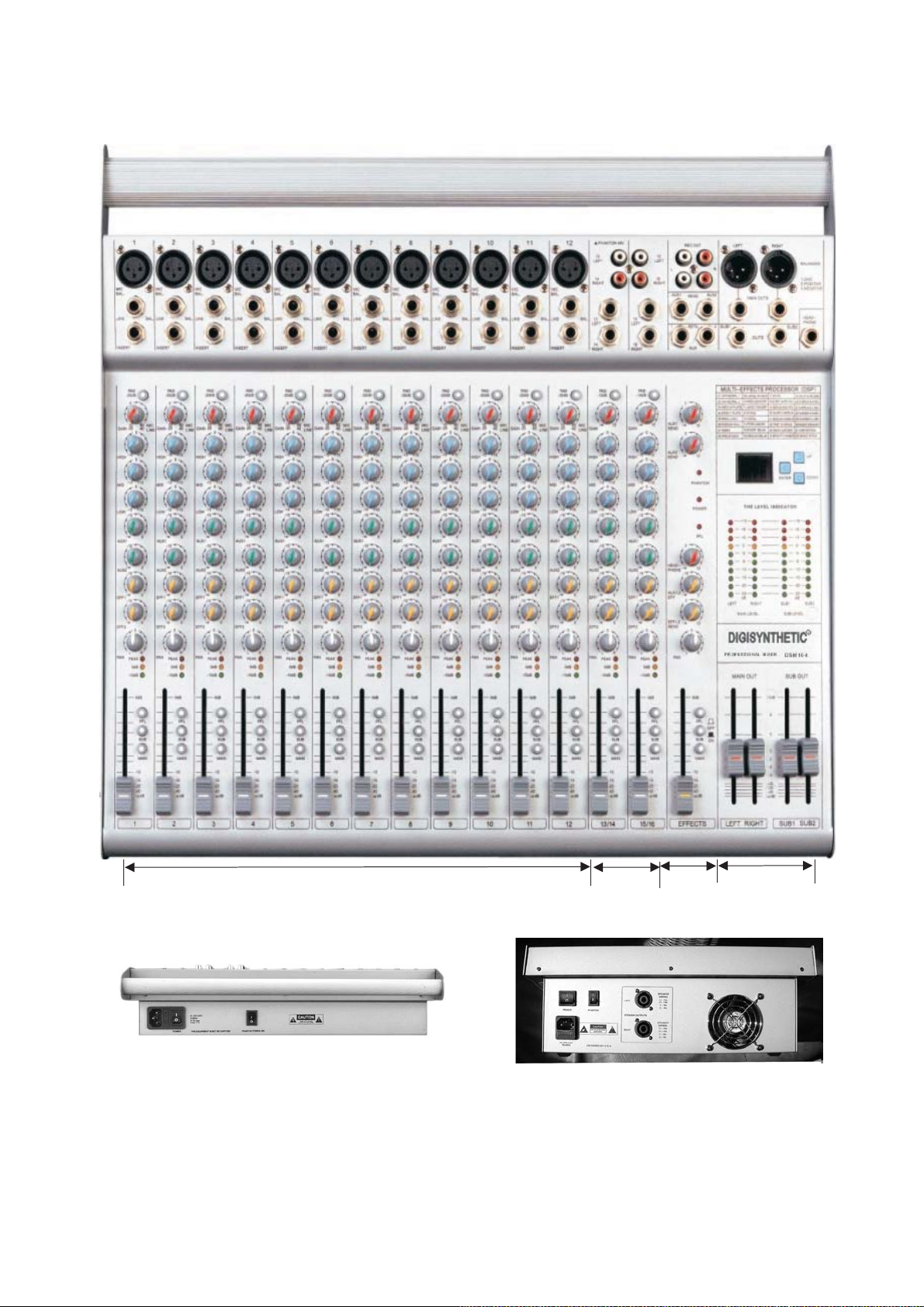
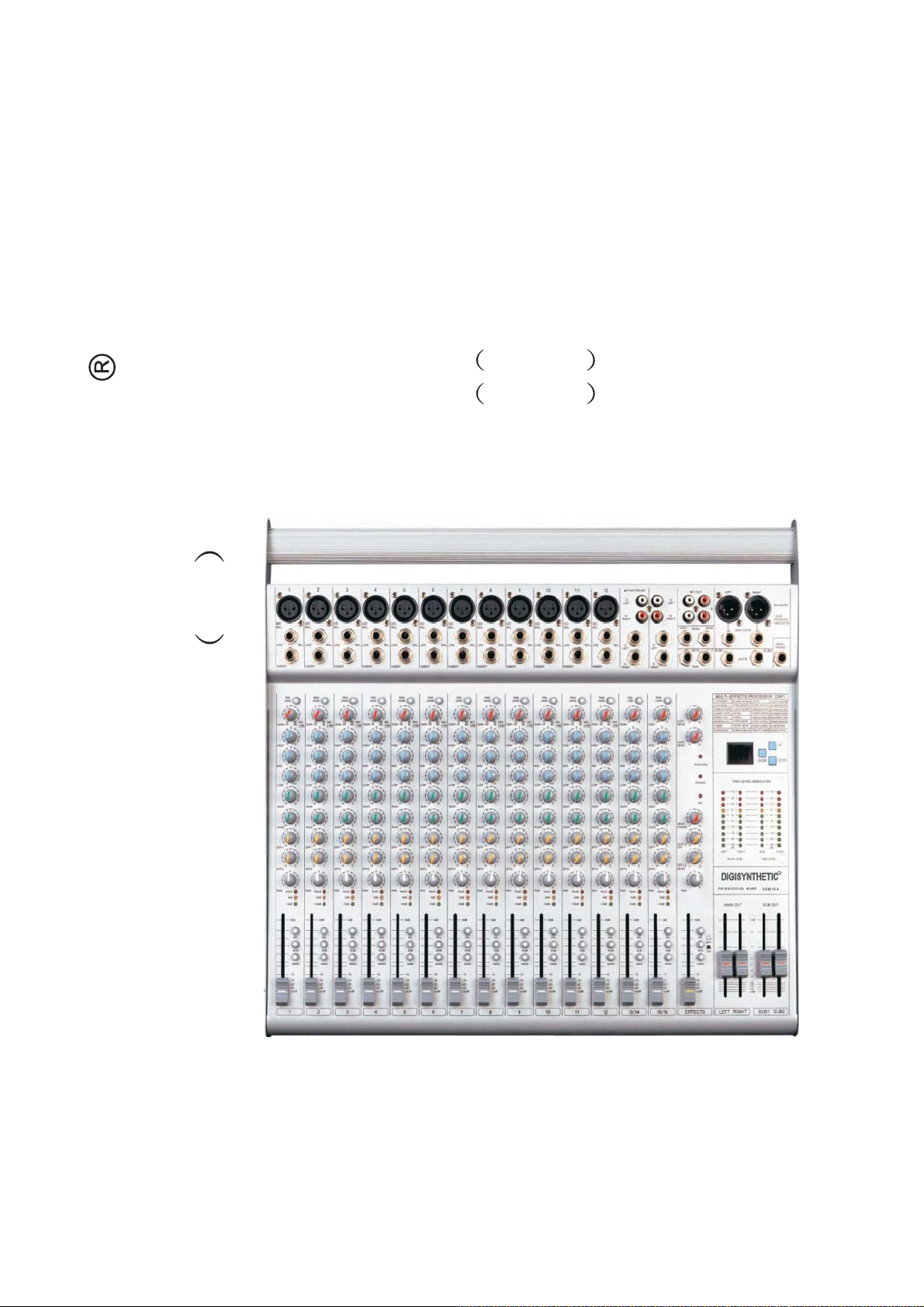
3 FRONT PANEL
MONO CHANNEL SECTION
DSM 104 DSM134
DSM 164 DSM204
REAR PANEL
STEREO CH ANNEL
SECTION
DSM 1043
DSM 1345
EFFECT
SECTION
MASTER SECTION
2

4 MONO CHANNELS SECTION
1 MIC
Neutrik electronically XLR connector
1
input socket. For connecting low level
signal sources, such as microphones or
other low impedance devices.
2) LINE
2
Balanced or unbalanced 1/4
(6.35mm)diameter stereo jack input
socket.For connection of high level sound
3
sources, such as keyboards, electric guitars,
electronic musical instruments or audio
playback units. Mono connectors can also
be used for automatic signal unbalancing.
When connecting a record rurnable , use
only an external R.I.A.A pre-amplifier.
4
3) INS
Stereo jack connector ( 6.3mm) for
5
connecting the input and output of a
remote device -noisegate, compresor,
equalizers - in series with the channel. The
command is only avaitable in mono
channels.
tones); tum the knob clockwise to boost mid
frepyencies (sound body is highlighted,
greater overall sound power and more nasal
tone).
LOW
- : controls the low range of signals (
15dB). When the knob is centrally positioned
(zero point), sound tone remains unchanted.
Turn the knob anticlockwise to Graduatly
reduce low frequencies (boom is neutralised,
excessively low sounds are removed); turn the
knob clockwise to boost low sounds are
removed); tum the knob clockwise to boost
low freuencies (more fullbodied sound,
highlighting of main signal frequencies,
prcussive sound more pronounced).
7) AUX1-AUX2
Use this control to the level of singal from
extemal soure and the main sigral control is
re-controled by MAS-TER or SUB section.
8) EFF1.EFF2
Use this control when you want to get effect
sound by adjustment of input signal, when
you don`t use extemal soure digital will be
working which in stallde inside.
4) PAD (-20dB)
6
When push this switch ,attenuates.the
input signal -20dB.
5) GAIN
Adjusts pre-amplifiction of signals from
the MIC (1)and LINE (2) inputs, ensuring
optimal performance of channel circuits.
For well-balanced Gain adjustment,
7
position the volum fader (14) at
approximately 3/4 of the control travel,
then adjust Gain until the PEAKLED (10)
lights up only at signal peaks.
6) HIGH-MID-LOW
8
The sound tone controls are positioned
after the GAIN control (5); the boosting of
these controls can cause channel
overloading , in which case the PEAK
LED will illuminate (10); turn the GAIN
control knob (5) in an anticlockwise
9
direction until PEAK LED(10)goes out.
- controls the high range of signals
HIGH:
10
( 15dB). When the knob is centrally
positioned (zero point), sound tone
remains unchanged. Turn the knob
anticlockwise to gradually reduce high
frequencies (vocals with less hiss,
reduction of background noise, cymbals
11
less cutting,etc.); Turn the knob clockwise
to boost high frequencies (sounds are
12
highlighted, vocals are more intelligible,
signal harmonics are emphasised).
13
- :controls the mid-range of signals(
MID
12dB). When the knob is centrally positioned
(zero point), sound tone remais unchanged.
Turn the knob anticlockwise to gradually
reduce mid frequencies (reduction of mid part
14
of sound, tones at extremes of high and low
ranges are emphasised, typical of dance music
9) PAN
Knob for adjusting signal stereo position, for
constant variation to the stereo image. Turn
the knob to the left (L) or right (R ) to vary the
proportion two signals; turn the knob to far
left or far right to eliminate the opposite
signal. To connect stereo soures, use two
mono channels; position one PAN to the left
(L), the other to the right (R).
10) PEAK.OdB.-10dB
Red LEDthat lights up when the signal level at
the tone control output is rear clipping
point.yillow LED is odb,green LED is -20dB.
11) PFL
Used for headphone monitoring of each
channel, regardless of the main mix. The
PFL(Pre-Fader Listen) function allows the
user to listen to the level before fader control;
subsequent adjustment of the fader control (14)
will not modify the level. The control is useful
during channel gain adjustment.
12) SUB1-2
Push the switch, can use sub1-2fader.
13)MAIN L-R
If you want to use master L-R fader, push this
switch.
14) FADER
ALPS 60mm slide control, with dust guard
.The fader adjusts channel signal level to be
sent to the Master MAIN controls L- R (41)
.Set the slider to 0dB for maximum signal
level; slide downwards to lower and
eventuaily eliminate ( ) the signal. For best
results, set the slide control to 3/4 of travel
upwards, then adjust the GAIN control (5) to
desired level.
3

5 STEREO CHANNELSECTION
15 LEFT RIGHT PIN JACK
15
This use for conectionctionction into
line level equipment.
16) LEFT.RIGHT
Line with connection 1/4 jack 0S line
input of L,R stereo and input the signal
16
of balance line level,if the signal input
the input terniant of right side , output
into the side only , if each signal input
the inpuy teminal of left &right output a
stereo of left & right.
17) PAD (-10dB)
When push this switch, atteruates the
input signal-10dB
17
18
18) GAIN
Adjusts unput sensitivity from 0dB to
+10dB
19) HIGH MID LOW
The sound tone controls are positioned
after the GAIN control (18); the
19
boosting of these controls can cause
channel overloading, in which case the
PEAK LEDwill illuminate (23); turn the
GAIN control knob (18) in an
anticlockwise direction until the PEAK
LED (10) goes out.
-HIGH
20
signals ( 15dB). When the knob is
centrally positioned (zero point ) ,sound
tone remains unchanged. Turn the knob
anticlockwise to gradually reduce
highfrequencies (vocals with less
cutting, etc.): turn the knob clockwise to
21
boost high frequencies (sounds are
higlighted, vocals are more intelligible,
signal harmonics are emphasised).
-MID:
22
signals ( 12dB). when the knob is
centrally positioned (zero point), sound
23
tone remains unchanged. Turn the knob
anticlockwise to gradually reduce mid
frequencies (reduction of mid part of
sound, tones at extremes of high and low
ranges are emphasised, typical of dance
24
music tones); turn the knob clockwise
to boost mid frequencies (sound body is
25
highlighted, greater overall sound
power and more nasal tone).
26
-LOW: controls the low range of
signals ( 15dB). When the knob is
centrally positioned (zero point), sound
tone remains unchanged. Turn the knob
anticlockwise to gradually reduce low
27
frequencies (boom is neutralised,
excessivel low sounds are removed);
: controls the high range of
controls the mid-range of
turn the knob clockwise to Boost low
sounds are removed); turn the knob
clockwise to boost low freuencies (more
fullbodied sound, highlighting of main
signal frequencies, percussive sound
more pronouncad).
20) AUX1 AUX2
Use this control to the level of signal
from external soure and the main signal
control is recontroued by MASTER or
SUB section.
21) EFF1 EFF2
Use this control when you want to get
effect sound by adjustment of input
signal, when you don`tuse extemal
soure digital will be working which
installed inside.
22) PAN
Knob for adjusting signal stereo
position,for constant variation for the
stereo image .Turn the knob to the left
(L)or right (R) to vary the proportion of
the two signals; turn the knob to far left
or far right to eliminate the opposite
signal. To connect stereo soures, use two
mono channels; position one PAN to
the left (L), the othe to the right (R).
23) PEAK 0dB-10dB
Red LED that lighs up when the signal
level at the tone control output is rear
clipping point. yellow LED is 0dB,
green LED is-20dB.
24) PFL
The PFL (pre Fader Listen) function
allows the level to be listened to before
the action of the volume control
25) SUB1-2
Push the switch, can use sub1-2fader
26) MAIN L-R
If you want to use master L-R fader,
push this switch.
27) PADER
ALPS 60mm slide control , with dust
guard. The fader adjusts channel signal
level to be sent to the main Master
MAIN controls L-R(41). Set the slider
to 0dB for maximum signal level; slide
downwards to lower and eventually
eliminate ( ) the signal.
4

28
29
6 EFFECT SECTION
28 REC OUT
This jack can be connected with cassette deck when recording the mixed
out.
29) AUX1.SUX2 SEND
Unbalance jack connectors for connection of monitors, either amplified or
for amplification; the output signal level is regulated by the Aux1.aux2
controls.
30
31
32
33
30) AUX1.AUX2 RET
Input connector allowing the output of the remote effect device to be
connected to the mixer.
31) AUX1.AIX2 SEND CONTROL
They regulate the general level of the monitor line signals received from
the input channels for sending to the monitor spedkers of the audio system
connected to the mixer by means of the AUX1. AUX2 outputs
32) PHANTOM LED .POWER LED.PFL LED
PHANTOM LED that lights up when push the phantom power switch,
power LED that leghts up when the power is on , PFL LED lights up
when the PFL switch is pressed.
33) HEADPHONE VOLUME CONTROL
Controls the level of the headphone listening volume.
34 )AUX1-2EFF
Controls the level of the EFFECTS signal to be send to the AUX1-2 SEND.
35) EFF1-2SEND
They regulate the general level of the effect line signals received from the
input channels for sending to the internal effect section.
36) PAN
Using by this control, you can adjust echo sound between left &right.
38
39
40
35
36
37
34
37) PFL
Allows headphone monitoring of the level of the EFF2 effect. The PFL (Pre
Fader Listen) function allows the level to be listened to before the action
of the volume control.
38) SUB1-2
Push the switch, the effect signal can to be the SUB1-2 fader.
39) MINA L-R
Push the switch, the effect signal can be main L-R fader.
40) EFFECT FADER
Control of the level of the effect1-2 signal level to be sent to the main, SUB
out outputs.
5

41
42
7 MASTER SECTION
41) MAIN OUT
XLR connectors which supply the signals controlled by the
MAIN LIR Fader (56), the signal taken from these outputs
requires use of a remote amplifier for connection to the speakers
if active spea kers (with bullt -in amplification) are used,direct
connection without a remote amplifier is possible .
42) HEAD PHONE
Balanced stereo jack connector for connection of headphones
with min ,impedance 32 Ohm.
43
44
43) SUB OUT
The terminal to be output with the volume control against
inputting signal into SUB1-2board.
44) OUTPUTS LEVEL INDICATOR
LEDS for display and decibel measurement of the output signal
levels.
45) SUB1-2FADER
Using by this control, you canadjust SUB1-2output level.
46)MAIN L-R FADER
Using this control, you can adjust MAIN L-R output level.
45
46

8.MULTEFFECT
8
47 MULTI-EFFECTS PROCESSOR
01 CATHEDRAL 1 12 STAGE 23 MED FLANGER
02 CATHEDRAL 2 13 VOCAL 24 BRIGHT FLANGER
03 MEDLUM PLATE 14 PERCUSSION 25 DELAY&REVERB
04 BRIGT PLATE 15 SHORT DELAY 26 CHORUS&MREV
05 SMALL HALL 16 MEDIUM DELAY 27CHORUS&LREV
06 MEDLUM HALL 17 ECHO 28 FLANGER&MREV
07 ROM 18 SHORT GATED REV 29 FLANGER&LREV
08 MED STUDIO 19 MED GATED REV 30 RADIO SPEAKER
09 LARGE STUDIO 20 SLOW CHORUS 31 DISTOR TION
10 MED CONCERT 21 MEDIUM CHORUS 32 MAGIC PITCH
11 LARGE CONCERT 22 FAST CHORUS
47
48
49
48)UP DOWN
Selects the type of effect.
49)ENTER
When you selects the type of effect, please push the key.

9 SUPPLYAND POWER SECTION
50
51 52
53
50
51
52
53
54
50 AC POWER CARD
AC200V-240V 50-60Hz
51 FUSE HOLDERS
When occur a problem on this appliance,the fuse will be cut off power to prevent fron problem. Fuse: TIA
(DSM-104 DSM-134 DSM-164 DSM-204) T4-6A(DSM-1043 DSM-1345)
52) POWER SWITCH
Push this switch ON , when you want to operate, the power LED (32) will be light up.
53) PHANTOM POWER SWITCH:
Switch for activating the 48Vpower on the MIC input connectors (1)of the mono channels; the LED
illuminartes to indicate the power is on. The phantom power supply is necessary for many professional
capacitor microphones.
54) OUTPUTSL/R
Speakon connector sockets. These allow a pair of loudspeaker enclosures to be connected to the built-in
amplification circuit. These enclosures must have an minimum impedance of 4ohm.

 Loading...