

Page 1
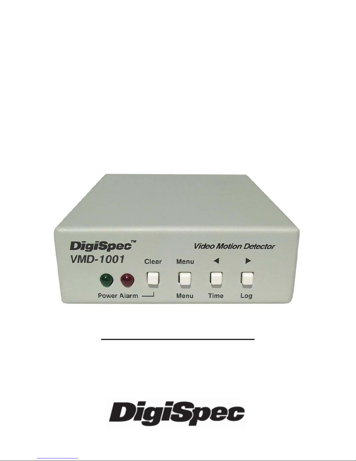
VMD-1001
Digital Video
Motion Detector
Version G
Operation Manual
Page 2

Introduction ..................................................................... 3
Features ........................................................................... 4
Connecting the Video .................................................... 6
Types of Cameras .............................................. 6
Cable .................................................................... 6
Lighting ................................................................ 7
Video Input & Output ........................................ 7
Connecting the Alarms ................................................. 8
Alarm Output ....................................................... 8
Connecting the Power .................................................. 9
Normal Operating Mode ................................................ 10
Front Panel .......................................................... 10
Button Operation ................................................ 10
On-Screen Displays ....................................................... 12
Present Time Display ........................................ 12
Log Display ......................................................... 13
Video Loss .......................................................... 13
Programming the VMD1001
Main Menu .............................................................................. 14
Security Code .........................................................................15
Alarm Setup .......................................................... 17
Sensitivity Level ................................................ 17
Tracking Level .................................................... 18
Relay Hold ........................................................... 19
Relay Contact ..................................................... 19
Buzzer .................................................................. 19
Alarm Zones ........................................................ 20
Clock Format ...................................................... 20
Clock Set ............................................................. 21
Alarm Log / Clearing ......................................... 22
Warranty ........................................................................... 24
Specifications ..................................................................... 26
Emergency Security Code Tear Out Page ........................................... 27
2
TABLE OF CONTENTS
Page 3
INTRODUCTION
Congratulations on your purchase of the VMD-1001 Digital Video Motion Detector . Y ou are now the owner of one of the most innovative, low
cost video motion detectors available today. We would like to personally thank you for your purchase and would like to provide you with
additional information on this remarkable product. The VMD-1001 analyses the video image 30 times per second to assure instantaneous
motion detection. By utilizing RISC processing, the VMD-1001 handles
millions of calculations per second, which greatly decreases the decision time and increases reliability.
Traditionally, motion detection has been used for surveillance and security applications. This unit is perfect for indoor or outdoor, low light
and difficult applications. Regardless of the job, the VMD-1001 can
handle it.
This ground breaking technology is representative of our commitment
to incorporate Quality , V alue and Innovation in every product we manufacture. We are and will continue to be the leader in Digital Video Motion Detection Technology .
3
Page 4

FEATURES
- Compact Size
- Simple Installation and Easy Set up
- 198 Independently Selectable Zones
- 99 Levels of Sensitivity
- Duration Settings from 0-99 seconds
- On-Screen Programming
- 100-Entry Event Log
- User Access Security Code
- No external synchronization required
- Low Power 7-15VDC @ 50mA
4
Page 5

CONNECTING THE VIDEO
Type of Cameras
Precautions: The VMD-1001 functions best with high quality video
cameras. Cameras must be securely locked down so the picture is stable
and jitter free. If the picture jitters or the Video Motion Detector’s (VMD)
character display jitters, the VMD may false trigger . If the camera has
any sync or phase adjustments, try adjusting these first.
To select the right camera for your application (i.e. indoor , outdoor , low
light, no light), you should consider the advantages and disadvantages
of each type.
CCD: High quality CCD cameras will work well with the VMD-1001.
The higher the resolution, the more precise the motion detection. CCD
cameras work equally well in both indoor and outdoor enviroments. It is
recommednded that B&W CCD cameras be used in outdoor applications due to their increased resolution. B&W low light level CCD cameras should be used in low light conditions. CCD cameras are sensitive to Infrared (IR) light and can be used for night vision with the aid of
an Infrared Illuminator .
IR: Infrared cameras should be used for no light applications or very
sensitive night vision applications. IR cameras are better equipped for
night vision than CCD cameras.
Cable
It is important that you use the proper cable type and installation procedures when installing the cameras and your VMD. Make sure you use
standard RG-59U coaxial cable with at least 95% braided shield for
video transmission. When installing, make sure that you do not run the
cable near any power lines for they may cause interference in the video
transmission. If you are cabling between floors or long distances, use
conduit to protect the cable from interference. Proper protection of the
video cable from external power interference, weather, and water is
5
Page 6

important to ensure a clear transmission of video signal and reliable
motion detection.
Grounding problems between the various components of a video system may cause noise or hum bars to appear in the video image. This
must be eliminated by properly grounding all equipment to an earth
ground and making sure all shields are intact in all video coaxial cables.
Grounding problems will effect the reliability of motion detection.
Lighting & Enviromental Conditions
Unless a camera is in a controlled enviroment, fluctuations in conditions will occur . The VMD-1001 provides the flexibility to configure the
Video Motion Detector for two separate sets of conditions.
Florescent Lighting: Gradual or sudden lighting changes, video noise,
intermittence or glitches in video lines, or power surges can be ignored
by the VMD-1001. T o compensate for such occurrences a balance must
be reached in the configuration of the motion criteria (see Motion Criteria). Fluorescent light may result in high speed flickering when a CCD
camera is used. V arious cameras have shutter selections for flickerless
option or you may have to disable the Auto White balance feature on
DC versions. Another solution is to change the lighting ballast to an
electronic one that operates at a higher frequency than the video sync
signal.
Video Input / Output
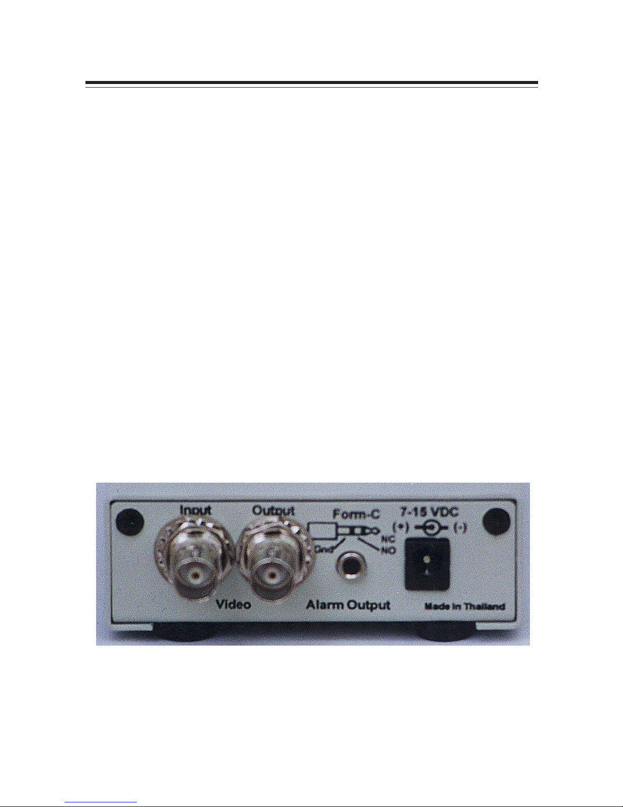
The video input and output are located on the rear of the unit. (see
Figure 1). The video input connects to the video source via the left BNC
connector. The video output connects to a display, recording device,
switcher, or other equipment via the right BNC connector. Both the
input and output are 1 V P-P into 75 ohms unbalanced EIA standard
RS-170A / NTSC or CCIR / P AL video format. Improper input termination or looping will cause the video level to be too low and effect the
motion detection. Improper output termination will make the image or
the video recording poor .
6
Page 7
Alarm Output
The VMD-1001 has one Form-C alarm output with a normally open (N/
O) and normally closed (N/C) configuration. When power is lost, the
contacts are as follows.
The contacts change state (open to closed N/O, or closed to open N/
C) whenever an alarm occurs. An alarm occurs when the VMD-1001
detects motion and the alarm has been enabled by pressing the ALARM
ON-OFF button (red LED on or slow flashing). The contacts remain
closed or open for the duration programmed in the Relay Hold time.
The location of the alarm output connector is seen in Figure 1. The
state of the relay when there is no alarm can be selected as N/C or N/
O so that power loss will indicate either an alarm or no alarm. For more
information, consult the Relay Contact Section of this manual under
Alarm Setup.
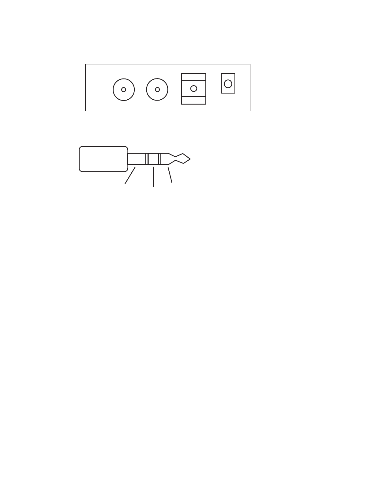
Some equipment may require a dry contact closure (normally open).
Connect such equipment to the N/O and common leads. For a normally closed alarm, connect between the N/C and common leads. There
Input Output
Alarm
Form-C
NO
NC
Com
Power
7-15VDC
Common NO NC Figure 2 - Alarm Plug
Connecting the Alarms
Figure 1 - Back Panel Diagram
7
Page 8

is no polarity; these leads may be swapped around. Other equipment
may require a closure to ground. In this case, a ground connection will
be provided on such equipment. Connect the common lead to ground
and N/O lead to the input of the equipment. There is no voltage on the
alarm connectors of the VMD-1001. No damage can be done by incorrect wiring.
For installation guidelines, consult the Relay Contact Section of this
manual under Alarm Setup.
Connecting the Power
The VMD-1001 operates from a DC supply range from 8V to 15VDC.
The power input connector , a st andard 2.1mm power jack, must have
positive (+) on the center and negative (-) or ground, on the outer shell.
The unit is reverse protected and correct polarity is indicated by the
green Power LED being lit on the front panel.
For mobile operation, a negative ground system is required, unless the
video ground is isolated from the automobile chassis ground. If operated in a vehicle, make sure the power supplied to the VMD-1001 is
properly filtered so alternator , radio or other equipment does not generated noise that might effect the motion detection performance. The
unit may be operated off of a regular 1 10 or 220 V AC household supply
using a transformer to supply the required 8-15VDC power .
8
Page 9
NORMAL OPERATING MODE
Front Panel
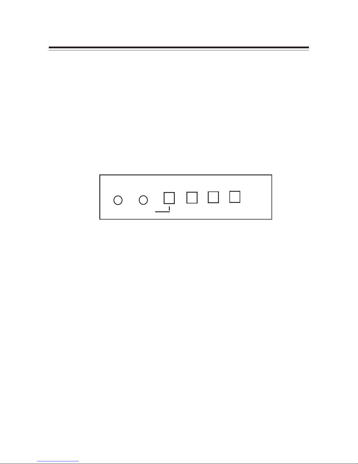
Four buttons on the front panel give full control of the unit.
The two LEDs indicate the general state of the unit. The green Power
LED indicates appropriate power is applied. The red Alarm LED indicates the unit is armed when solid and alarmed when flashing rapidly.
Note: Motion detection is inhibited during setup and during the time or
log display .
Figure 3 - Front Panel
In the normal operating mode, the VMD is processing alarms (if enabled) and displaying the date and time (if enabled). The 4 buttons
provide all the necessary functions.
Alarm Button
This button toggles between alarm enabled and disabled. When enabled, the VMD-1001 will generate alarms whenever the motion detector qualifies valid motion. When the alarm is disabled, no alarms will be
generated. However, the red LED will still flash whenever motion is
detected. This feature is useful when setting the Sensitivity Level. The
red LED will light solid or slow flashing when the alarm is enabled.
If an alarm is active (i.e. the VMD-1001 is generating an alarm) pressing
the Alarm button will clear the alarm. After that, the alarms will toggle
between enabled and disabled.
9
Clear Menu Z [
Menu Time Log
Power Alarm
Page 10

Menu Button
This button brings up the Programming Menu as white letters overlayed
on the video and starts the Programming Mode.
Time Button
Momentarily displays the current data and time on the screen.
Log Button
Displays Log Page #1 and starts the Log Display Mode. The most recent alarm events, and their date, time, and alarm number are displayed. Pressing the Left or Right button scrolls forward or backward
through the log. Pressing the Clear button clears the Log Page and
reverts back to normal running operation. Normal operation also resumes when no buttons have been pressed for 10 seconds.
Remember, motion detection is inhibited when the log is being displayed.
10
Page 11

ON-SCREEN DISPLAY DURING RUNNING
OPERATION
Alarm Display
Whenever an alarm occurs, a message is shown on the bottom
line of the screen which indicates the date and time of the alarm as
well as the number of accumulated alarms (1-99). This display will
continue for the duration of motion detection plus the programmed
alarm Hold time. In USA and 12 hour format, the display will appear as follows.
MM/DD/YY HH:MM:SS A##
where ## is the number of alarms accumulated since last clearing
the log.
Present Time Display
The system date and time will momentarily display whenever the
Time button is pressed.
PRESENT TIME
MM-DD-YY HH:MM:SSA
MM-DD-YY
Month (01=JAN, 02=FEB, etc.) Date (day of the month) and Y ear .
The sequence of these can be changed in the Clock Format Menu.
USA or European formats are selectable.
HH:MM:SSA
Hours, minutes, seconds, and am/pm indicators. The format can
be changed in the Clock Format Menu to display 12 hour mode
(with am/pm) or 24 hour mode (military time). The method used
here determines the mode for the T imer Mode menu screen.
11
Page 12

Log Display
Pressing the Log button will display the alarm log, eight alarms at a
time, starting with the most recent as number 1.
Sample Alarm Log:
Alarm Log 01 <=note:page number , press Left
04/02/99 08:05A 01 & Right to scroll through the
04/02/99 08:02A 02 pages of alarm events
04/01/99 03:25P 03
03/25/99 12:15P 04 <= each entry is: date, time,
and alarm number
Video Loss
When video is lost, the VMD stops all processing. An alarm will
occur immediately and will be displayed accordingly .
12
Page 13

Programming the VMD1001
T o st art the programming, press the Menu button. The Main Menu
page will be displayed.
Main Menu
MAIN MENU
-> SECURITY CODE
ALARM SETUP
ALARM ZONES
CLOCK FORMA
CLOCK SET
ALARM LOG
The 6 items on the Main Menu are the main catagories for setting
the VMD. From this menu, you branch to the menu page associated with each item, where the settings are changed.
During programming, the four buttons function as follows:
Clear Button
Clears the programming mode at any time during programming
and reverts back to normal running operation. Changes will be saved
to non-volatile memory and will take immediate effect.
Menu Button
Steps through the programming options which are displayed onscreen with flashing prompts. Each time the Menu Button is pressed,
the next prompt will be selected, indicating a change can be made.
At the end of each menu page, the last prompt will wrap around to
13
Page 14

the top of the page (the first prompt).
Left Button
Use this button to reduce the value if it is numeric or to sequence
backwards if the value is text. During zone pattern settings, the
cursor will move to the left. Holding down the button will cause its
action to repeat rapidly .
Right Button
Use this button to increase the value if it is numeric or sequence
forwards if the value is text. During Zone Pattern settings, the cursor will move to the right. Holding down the button will cause its
action to repeat rapidly .
Security Code
SECURITY CODE
-> >00< 00 00 00
SECURITY ENABLE?
YES >NO<
ACCEPT CHANGES?
YES >NO<
A security code may be set using this menu to prevent accidental
changes to the alarm criteria settings and subsequent missed
alarms.
The Security Code is essentially a password that consists of four
groups of numbers (each from 00 to 99)
14
Page 15

To set a security code, access this menu from the main menu by
selecting Security Code using the Menu button. When the right arrow is pointing to the Security Code, press the Log or Right (>)
arrow button. Then Menu button moves the flashing cursor >< around
the screen. Move the cursor to the set of numbers you wish to change
and then use the Left or Right arrow buttons to change the value.
For example, to set a security code of: 01 02 03 04, move the
cursor to the first set of zeros (00) using the Menu button and press
the Right arrow once to change the value to “01”
Press the Menu button to move to the next group of zeros (00) and
again press the Right arrow to change this value to “02”. Repeat
this for the third and fourth sets to set “03” and “04” respectively .
Next, using the Menu button, move the cursor to the Security Enable? prompt and press the Right arrow button to toggle to “Y es”.
Finally , move the cursor to the Accept Changes? prompt and toggle
to “Y es”.
Once you have set the code, enabled it, and accepted the changes,
press the Clear button to exit this menu.
At this point, the security code numbers you set will be required to
enter the Programming menu. Page 27 is provided to record the
security code.
15
Page 16

Alarm Setup
The Alarm Setup menu is the most important setup for the operation of the motion detector . It is used to adjust criteria for qualifying
a valid alarm.
ALARM CRITERIA
SENS >02<
TRACK 0.1
HOLD 0.05
RLY CONTACT
>NC< N0
BUZZER
ON >OFF<
The Two Motion Detection Criteria
There are 2 motion detection criteria for qualifying an alarm with
respect to contrast from background, and duration of motion.
Sensitivity Level adjusts for the size of a moving object that will
trigger an alarm. A small object requires a higher sensitivity level
to trigger . A larger object will trigger at a lower sensitivity . The Sensitivity Level has a range of between 1 and 99.
Each camers’s sensitivity must be set individually and adjusted
according to its use. Use the Menu button to highlight the SENS
setting and either increase or decrease the value using the Left or
Right arrow buttons. The right arrow button will increase the sensitivity , and the left arrow button will decrease the sensitivity .
Configuration Hints: To assist in adjusting the sensitivity, disable the alarm (red LED off) using the Alarm button. The red LED
will illuminate only when motion is detected. If it blinks often when
16
Page 17

there is no motion, the sensitivity is too high. If the LED does not
illuminate with motion, the sensitivity is too low .
In outdoor applications, variables such as shadows, precipitation,
etc. call for lower sensitivity . These conditions can be screened out
so only relevant motion is detected. Experimentation will provide
helpful information in determining the correct level.
The sensitivity must be set appropriately for each camera location.
If the sensitivity is too low , an alarm may never occur. If the sensitivity is too high, shadows and noise may falsely trigger alarms. Power
induced noise, thermal noise, and snow from the camera are types
of noise that may cause false triggering if the sensitivity is too high.
To filter out noise, set the sensitivity to a maximum and decrease
until the false alarms are stopped. Use the Alarm OFF mode to
detect false alarms by showing a motion trigger as a flash of the
Alarm LED.
Tracking Level is the length of time, in tenths of a second, that
motion must be continuously occuring to activate the alarm. T racking can be set for 0.0 seconds for instantaneous triggering or from
0.1 to 8.0 seconds for triggering equal to that number of seconds.
The T racking is crucial to motion calculation.
Tracking can filter out unwanted or random motion. It must be suf ficiently long to filter out this motion, but short enough to capture
required events.
Use the Menu button to highlight the T rack setting and either increase or decrease the value using the Left or Right arrow buttons.
Configuration Hints: The Tracking criteria makes the VMD-1001
excellent for outdoors. By increasing the number of seconds, many
natural occurences can be maske out. For example, lightning will
last no more than 0.4 seconds. A camera shaking in the wind takes
perhaps 0.5 to 0.6 seconds. Similarly , a tree branch shaking by a
17
Page 18

gust of wind might take 1.0 second. If the tracking is too low , sudden changes such as lighting, insects near the camera, flashing
lights, snow , and rain may falsely trigger alarms. The T racking attribute can require up to 8.0 seconds of continuous motion which is
more than sufficient to mask out most natural phenomena as well
as intermittent motion. If the T racking is set too high, the required
object moving in the image may not trigger an alarm. Thus, a balance between required and unwanted motion must be achieved.
Experimentation is required to properly set this alarm criteria.
HOLD is the length of time (in seconds) that the relay will output an
alarm condition to an external device before it resets. It can be set
from 0:00 to 3:00 minutes in increments of seconds. Use the Menu
button to highlight the Hold setting and either increase or decrease
the value using the Left or Right arrow buttons.
Configuration Hints: The length of time you will output an alarm
depends on the type of device being controlled. A light or a bell
may require a longer alarm time. An external matrix switcher or
VCR will usually require only a pulse. In this case, you may want to
set the alarm output time to 1 second.
RLY CONTACT allows you to select whether the relay contacts
you use will be normally closed (NC) or normally opened (NO) during an alarm. Use the Menu button to highlight the RL Y CONT ACT
setting and either select NC or NO using the Left or Right arrow
buttons.
The BUZZER simply allows you to enable or disable an internal
alarm buzzer . Use the Menu button to highlight the BUZZER setting
and either select ON or OFF using the Left or Right arrow buttons.
Press the Clear button when complete.
Configuration Hints: Determine if a power failure should indicate an alarm or no alarm. With VMD power OFF , wire up to the N/
O or N/C contacts of the VMD which gives the proper indication.
18
Page 19

Power up the VMD using the Relay Contact menu, select the proper
choice (NO or NC) which indicates no alarm when in fact no alarm
exists.
Alarm Zones
By selecting Alarm Zones you are able to change the detection
zones of the video motion.
Upon entering this menu, the top left most zone will be flashing a
rectangular box. The default is all zones active which is signified by
the rectangular box.
To deselect a zone, press the Menu button to toggle to the white
dot in the center of the zone. This dot signifies the zone is not active and all motion in this zone will be ignored.
Use the Left or Right button to select the previous or adjacent zone.
When you reach the bottom right most zone the cursor will wrap to
the top left most zone.
Continuous holding of the Right or Left button will cause the cursor
to move quickly to find the correct zone faster .
You can also quickly select or deselect all zones by holding the
“Menu” button in when the on-screen display is either selected or
deselected. Then hold continuously the Left or Right button. Rapid
selection or deselection of the zones very quickly will then be possible.
Clock Format
In this menu the T ime format can be configured to either 12 hour or
24 hour format, and the Date to either USA or European format.
19
Page 20

Use the Menu button to highlight the T ime Format setting and either select 12H or 24H using the Left or Right arrown buttons.
TIME FORMAT
-> >12H< 24H
DATE FORMAT
>MDY< DMY
Use the Menu button to highlight the Date Format setting and
either select MDY or DMY using the Left or Right arrow buttons.
MDY: Month, Day, Year USA Format
DMY: Day, Month, Year European Format
Clock Set
This menu provides the configuration option of setting the current
Date and T ime. The T ime can be configured for AM or PM, if in the
previous menu (Clock Format), 12 hour format was selected.
Use the Menu button to highlight the Hours setting and either increase or decrease the Hours using the Left or Right arrow buttons.
Use the Menu button to highlight the MINS setting and either increase or decrease the Hours using the Left or Right arrow buttons.
20
Page 21

Use the Menu button again to move down and select either AM or
PM using the Left or Right arrow buttons.
TIME SET
-> HOURS >09<
MINS 10
>AM< PM
DATE SET
YEAR 99
MONTH 04
DAY 01
Use the Menu button again to move down to Y ear and increase or
decrease the year using the Left or Right arrow buttons. Do the
same for Month and Day .
Press the Clear button when complete.
Alarm Log
The Clear Log? prompt provides the option for clearing (deleting)
the alarm log from memory and restarting the alarm log. The alarm
log holds up to 99 events. After 99 events have been logged, new
alarms overwrite the oldest (or first) events in the log.
Use the Menu button to position the cursor under Clear Log? and
the Left or Right arrow buttons to toggle Yes or No.
Note: If you clear the log, “Please Wait” will appear briefly on the
screen while this command processes.
21
Page 22

Configuration Hint: If you wish to preven accidental loss of the
alarm log, be sure to setup a security code.
CLEAR LOG?
-> YES >NO<
ENABLE LOG?
YES >NO<
Sample Alarm Log:
Alarm Log 01 <= Note: page number, press
04/02/99 08:05A 01 Left & Right to scroll through
04/02/00 08:02A 02 the pages of alarm events.
04/01/99 03:25P 03 <= each entry is: date, time and
03/25/99 12:15P 04 alarm number
The Enable Log? menu item will enable or disable the log feature. We recommend that you disable the Log if you normally
have more than 30 alarms per day , or if you are not using the Log
feature.
Use the Menu button to position the cursor under Enable Log?
and the Left or Right arrow buttons to toggle Yes or No.
Press the Clear button when complete.
22
Page 23

Programming Notes
Alarm Zone Settings
[] [] [] [] [] [] [] [] [] [] [] [] [] [] [] [] [] []
[] [] [] [] [] [] [] [] [] [] [] [] [] [] [] [] [] []
[] [] [] [] [] [] [] [] [] [] [] [] [] [] [] [] [] []
[] [] [] [] [] [] [] [] [] [] [] [] [] [] [] [] [] []
[] [] [] [] [] [] [] [] [] [] [] [] [] [] [] [] [] []
[] [] [] [] [] [] [] [] [] [] [] [] [] [] [] [] [] []
[] [] [] [] [] [] [] [] [] [] [] [] [] [] [] [] [] []
[] [] [] [] [] [] [] [] [] [] [] [] [] [] [] [] [] []
[] [] [] [] [] [] [] [] [] [] [] [] [] [] [] [] [] []
[] [] [] [] [] [] [] [] [] [] [] [] [] [] [] [] [] []
[] [] [] [] [] [] [] [] [] [] [] [] [] [] [] [] [] []
Sensitivity Level_______________
T racking Level ________________
Hold Time ___________________
Relay Contact ________________
Buzzer ______________________
23
Page 24

24
LIMITED W ARRANTY
(T erms and Conditions)
For 2 Years from the date of shipment, Seller warrants to Buyer that the
Product is free from defects in material or workmanship under normal use
and service. Equipment manufactured by other than Seller but furnished by
Seller carries the same warranty to Buyer as Seller receives from the other
manufacturer, notwithstanding any provision to the contrary. If Buyer has
specified a particular manufacturer’s product which is not the brand standardly
supplied by Seller , Buyer shall look only to the other manufacturer’s warranty
and Seller shall not warrant such item.
EXCLUSIONS. Seller’s warranty does not cover the following:
(1) in-transit damage claims, improper handling by carrier or post office
(Note: only the consignee of the shipment can file a claim with the
common carrier)
(2) damages caused by incorrect use, modification, carelessness,
improper storage, hostile operating conditions, or unauthorized
service, installation or repairs without proper training from the Seller
(3) damages caused by fire, flood, lightning, collision, acts of God or
other events beyond the control of Seller
(4) products or parts thereof that have had serial numbers removed,
altered or defaced
(5) products returned without an RMA number and sales or delivery
receipt showing the date of original purchase
(7) use of components that do not meet Seller’s specifications
(9) external parts such as cabinets or keypads
(10) periodic maintenance and adjustments resulting from normal use
WARRANTIES EXCLUDED, SELLER EXPRESSLY DISCLAIMS AND EXCLUDES ANY EXPRESS OR IMPLIED WARRANTY OR MERCHANTABILITY OR FITNESS FOR A PARTICULAR PURPOSE WHICH EXCEEDS OR
IS INCONSISTENT WITH THE WARRANTY HEREIN EXPRESSLY SET
FORTH.
NON-WARRANTY CLAIMS. In the event Buyer makes a warranty claim and
Seller’s warranty does not apply, Buyer shall reimburse Seller for all reasonable expenses incurred by Seller in diagnosing the installation/repair problem.
Page 25

BUYER’S EXCLUSIVE REMEDIES. If the Product supplied shall fail to
conform to the contract or any applicable warranty, Buyer shall immediately
notify Seller of such condition and afford Seller a reasonable opportunity to
inspect said Product. Seller shall, at its option, either repair or replace such
nonconforming Product. Seller shall not be responsible for labor charges for
removal or installation of such equipment or material or charges for transportation, handling and shipping except as provided in Seller’s written service
policy . No Product shall be returned without Seller’s prior written consent.
SELLER SHALL NOT BE LIABLE FOR ANY SPECIAL, DIRECT INCIDENT AL OR CONSEQUENTIAL DAMAGES OF A COMMERCIAL NATURE ARISING OUT THE USE OF OR INABILITY TO USE SELLER’S PRODUCT BY
REASON OF THE FACT THAT SUCH PRODUCT DOES NOT CONFORM
TO THE CONTRACT OR TO ANY EXPRESS OR IMPLIED WARRANTY.
SELLER’S MAXIMUM LIABILITY SHALL BE LIMITED TO THE COST OF
REPAIR AND/OR REPLACEMENT OF THE PRODUCT CLAIMED TO BE
DEFECTIVE OR NONCONFORMING, SUBJECT TO SELLER’S RIGHT OF
REMOV AL AND RETURN OF PRODUCT.
All of the foregoing constitute Buyer’s sole and exclusive remedy and Seller’s
sole and exclusive liability for supplying nonconforming or defective Product.
RETURNS. DigiSpec products are fully inspected and carefully packed to
ensure you are delivered a quality product in good condition. If you are not
fully satisfied with our product, returns of standard stocking items with no
restocking fee can be made within thirty (30) days of invoice to Buyer. All
such returns must have prior consent of Seller by obtaining an RMA number
and must include the sales or delivery receipt showing the date of original
purchase and be in an unused condition contained in its original packaging.
Any other returns must have prior written consent of Seller and are subject to
a restocking fee of fifteen percent (15%) and freight charges.
RMA NUMBER. The RMA (Return Material Authorization) number must be
obtained by contacting Seller prior to the shipment of the the product for
return. The RMA number is valid only for 15 days from the date of issue. The
RMA number must be clearly displayed on all shipping labels.
25
Page 26

SPECIFICATIONS
Video Input: 1V p-p, 75ohm, BNC
Video Output: 1V p-p, BNC, automatic loop-through on
power loss
Video Standards: EIA / NTSC, CCIR / P AL, and SECAM
(color or monochrome)
Pixel Resolution: 288 horizontal by 216 vertical
Power Supply: 7 to 15 V DC @ 50mA
Alarm Output: Form-C relay contacts Normally Open
(NO) and Normally Closed (NC)
each rated at 1A@250V .
Size: 4.5”Dx3.5”Wx1 1/8”H or 1 16Dx88Wx30Hmm
Weight: 14 oz. / .40 KG
Color: White with metal case
26
Page 27

Emergency Security Code
The Emergency Security Code for you VMD-1001 with serial number ________________ is 93 12 87 04.
Please do not inform any person or organization of this code except to gain access to this particular unit in an emergency.
Tear out this page and file in a secure area.
27
Page 28

DigiSpec Inc.
1906 Treble Dr .
Humble, T exas 77338
Tel: 281-540-6665 Fax: 281-540-6972
Email: [email protected]
Web Site: www .digispecvideomotion.com
 Loading...