

DigiSpec DTT-PRO Operation Manuals

DTTDTT
DTTDTT
DTT
-Pr-Pr
-Pr-Pr
-Pr
oo
oo
o
Digital Date / Time Titler
Operation Manual
May 2011
TM
2
DTTDTT
DTTDTT
DTT
-Pr-Pr
-Pr-Pr
-Pr
oo
oo
o
TO PREVENT ELECTRIC SHOCK, DO NOT REMOVE THE
COVER. DO NOT EXPOSE THE EQUIPMENT TO RAIN OR
MOISTURE. NO USER SERVICEABLE PARTS ARE INSIDE.
REFER SERVICING TO QUALIFIED PERSONNEL.
CAUTION!
RISK OF ELECTRICAL SHOCK!
DO NOT OPEN!
W ARNING!
THIS EQUIPMENT GENERA TES, USES, AND CAN RADIA TE RADIO FREQUENCY ENERGY AND IF NOT INSTALLED AND USED IN ACCORDANCE WITH THE INSTRUCTION MANUAL MAY CAUSE INTERFERENCE TO RADIO COMMUNICATIONS. IT HAS BEEN TESTED AND
FOUND TO COMPLY WITH THE LIMITS FOR A CLASS A COMPUTING
DEVICE PURSUANT TO SUBPART J OF PART 15 OF FCC RULES,
WHICH ARE DESIGNED TO PROVIDE REASONABLE PROTECTION
AGAINST SUCH INTERFERENCE WHEN OPERATED IN A COMMERCIAL ENVIROMENT. OPERATION OF THIS EQUIPMENT IN A RESIDENTIAL AREA IS LIKEL Y TO CAUSE INTERFERENCE IN WHICH CASE
THE USER AT HIS/HER OWN EXPENSE WILL BE REQUIRED T O TAKE
WHATEVER MEASURES MAY BE REQUIRED TO CORRECT THE INTERFERENCE.

3
CONTENTS
Introduction..................................................................................................................................................4
Features & Specifications.......................................................................................................................4
Features...........................................................................................................................................4
Specifications................................................................................................................................4
Connections...................................................................................................................................5
Front Panel.....................................................................................................................................5
Rear Connector................................................................................................................. ............5
Operating Mode.............................................................................................................................6
Programming Mode......................................................................................................................6
TITLER SETUP ...............................................................................................................................6
TIME-DA TE...................................................................................................................... ................7
T-D SETTING.......................................................................................................................7
TIME FORMA T .....................................................................................................................8
DA TE FORMA T ..................................................................................................................8
DST........................................................................................................................................8
EXIT.......................................................................................................................................9
DISPLAY...........................................................................................................................................9
TITLER...............................................................................................................................10
TIME-DA TE........................................................................................................................10
VIDEO LOSS.....................................................................................................................10
VL OUTPUT ...........................................................................................................1 1
TIME-DA TE............................................................................................................11
CAPTURE.............................................................................................................12
VL MESSAGE.......................................................................................................12
EXIT.........................................................................................................................12
GRAYSCALE....................................................................................................................13
BORDER...........................................................................................................................13
EXIT.....................................................................................................................................14
Video Loss Detection............................................................................................................................14
Master Reset............................................................................................................................................14
Warranty....................................................................................................................................................15
FIGURES
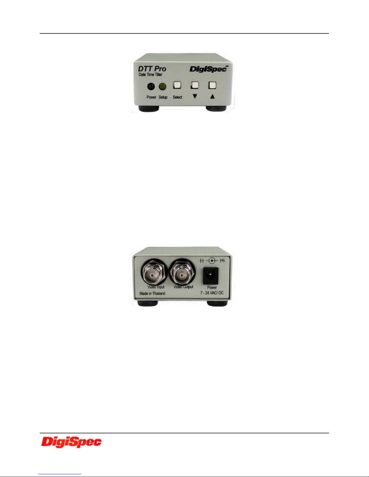
Figure 1: DTT-Pro Front Indicator LEDs and Programming Push buttons...............................5
Figure 2: DTT-Pro Rear Connections............................................................................................. .....5

4
SPECIFICATION
Video
Video Input / Output BNC - 1 VP-P Input +/- 20%, 1V P-P Output 75 Ohm Term. or UnT erm.
Video Format NTSC/EIA or P AL/CCIR
Display
Titler Format 20 Alpha-Numeric Character On/Off Select able
Date-Time Format On/Off Selectable
MMM-DD-YY HH:MM:SS A (A-AM, P-PM) 12Hr
MMM-DD-YY HH:MM:SS 24Hr
DD-MMM-YY HH:MM:SS A (A-AM, P-PM) 12Hr
DD-MMM-YY HH:MM:SS 24Hr
YY -MMM-DD HH:MM:SS A (A-AM, P-PM) 12Hr
YY -MMM-DD HH:MM:SS 24Hr
Clock Accuracy +/- 5 ppm
On-Screen Width 75% of active display width
Character Height 12 lines (5.8% of total image height)
Control / Programming
Control Interface 3 Front Panel Buttons: Select, Up, and Down
Status Indicators 2 Front Panel LEDs:Power (Greeen), Setup (Yellow)
Earth Grounding Screw T erminal on Bottom of Unit
Back-Up Battery Internal Rechargeable NiMH battery
Warranty 2 Y ears Part s and Labor
Size / Weight / Power
Size 3 3/8” D x 2 5/8” W x 1 1/8” H
85mm D x 62mm W x 30mm H
Weight 9 oz / .28 Kg
Power Multi Volt age Input 7.5-24 V DC @ 65mA or 24V AC @ 100 mA
2.1mm x 5.5mm DC Power Connector - Center Positive
INTRODUCTION
The DTT-Pro single-channel Date-T ime-Titler overlays date, time and camera identification onto a video image,
identifying precisely when and where an event has taken place. The output signal may be displayed on a monitor,
recorded on a VCR/DVR, or printed on a video printer. The characters have full programmability in 8 gray scales along
with background in 8 gray scales. In the event the video input fails or not used the DTT-Pro will output a composite video
image with the T/D T itle information visible. Full 7.5-24V DC or AC Operation. Power input full protected from surge and
lightning with screw terminal earth ground.
The DTT-Pro uses a precision crystal-controlled clock for unparalleled +/-5 ppm accuracy. Compatible with
both color and monochrome cameras NTSC/EIA or PAL/CCIR formats, its compact size and low power consumption
make it perfect for portable and covert applications. Fully programmable for all US and European Time/Date formats for
world compliance.
FEATURES
Displays Hours, Minutes and Seconds
Titles up to 20 Characters
Character Border Selectable 8 grayscale
Character Color Selectable 8 grayscale
Video Signal Loss Detection
Composite Video Output without Video Input
Power Failure Indicator
Low Voltage, Low Power AC/DC
NTSC / PAL Jumper Selectable
Works with Color or Monochrome Cameras
Information can be Positioned Anywhere On-Screen
FEATURES & SPECIFICATIONS
DTT-Pro (DA TE/TIME TITLER)
5
The DTT-Pro operates from a multi voltage input 7.5V to 24VDC 65 mA or 24 V AC 100 mA . The power
input connector is a standard 2.1mm x 5.5mm DC Coax power jack, must have positive (+) on the
center and negative (- or ground) on the outer shell. The unit is reverse protected for correct polarity and
is indicated by the Green Power LED being lit on the front panel.
Rear Connectors
Front Panel
CONNECTIONS
Video
Input/Output
The video input and output are located on the rear of the unit. (see Figure 2). The video input connects
to the video source via the left BNC connector. The video output connects to a display , recording device,
switcher, or other equipment via the right BNC connector . Both the input and output are 1 V P-P into 75
ohms unbalanced EIA st andard RS-170A / NTSC or CIR / P AL video format. Improper input termination
or looping will cause the video level to be too low and effect the text insertion. The video output is 1VPP whether terminated with 75 ohm or not and can drive two 75 ohm terminated loads without degradation. Additional output load will cause the level to decrease proportionally.
Power Input
Power Green Signifies power is supplied to the unit
Setup Y ellow This Yellow LED will light whenever going to the Programming mode
Programming push buttons
Select button Press this button to go to programming mode
Down button In the Operating mode press this button to move down the Title and Date-Time overlay on the screen.
In the Programming mode press this button to move down the cursor or change some setting.
Up button In the Operating mode press this button to move up the Title and Date-Time overlay on the screen.
In the Programming mode press this button to move up the cursor or change some setting.
LED Indicators
Figure 1: DTT-Pro Front Indicator LEDs and Programming Push buttons
Figure 2: DTT-Pro Rear Connections
DTT-Pro (DA TE/TIME TITLER)
 Loading...