

Page 1
1
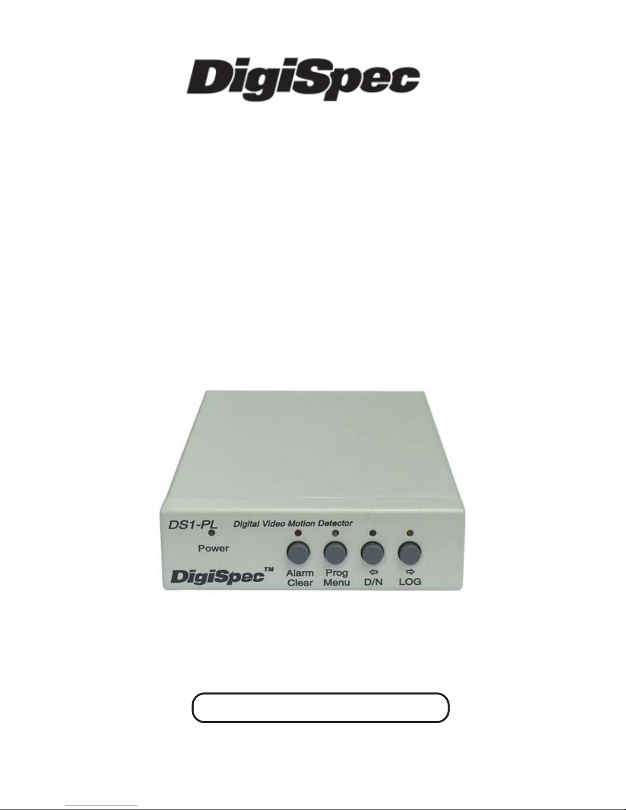
DS1-PL
July 2011
DIGIT AL OUTDOOR
VIDEO MOTION DETECTOR
TM
Version 6.17
OPERA TION MANUAL
Page 2

2
CONTENTS
Introduction ........................................................................................................................... 4
Features ................................................................................................................................ 5
5 Different Operation Modes ..................................................................................... 6
Motion Detection Parameter ..................................................................................... 6
Viewing Modes .......................................................................................................... 6
Motion Detection Set Up ............................................................................................ 6
Specifications ........................................................................................................................ 7
Detection Parameter ................................................................................................. 7
Zone Pattern Grid ...................................................................................................... 7
Alarm Outputs ........................................................................................................... 7
Connecting the Video ........................................................................................................... 8
Type of Cameras ....................................................................................................... 8
Cable ......................................................................................................................... 8
Lighting & Environment ............................................................................................. 8
Day / Night ................................................................................................................. 8
Florescent Lighting .................................................................................................... 9
Video Input / Output ................................................................................................... 9
Connecting the Alarms ........................................................................................................... 9
Alarm Output .............................................................................................................. 9
Alarm Connector DB-15 .............................................................................................. 10
Day / Night Inputs ...................................................................................................... 10
RS-232 ....................................................................................................................... 10
Connecting the Power ........................................................................................................... 10
Operation .............................................................................................................................. 11
Button Operation ....................................................................................................... 12
Normal Running Mode Button Functions ................................................................... 12
Programming Mode Button Functions ....................................................................... 13
Day / Night Mode ....................................................................................................... 13
Log Mode .................................................................................................................. 13
On-Screen Display during Running Operation ....................................................................... 14
Video Loss ................................................................................................................. 15
Programming the DS1-PL ...................................................................................................... 15
1. Motion Detection Menu .......................................................................................... 16
The Mode Setting .......................................................................................... 16
The Three Motion Detection Criteria ............................................................. 16
The Trigger Level .......................................................................................... 18
The Sensitivity Setting ................................................................................... 19
The Tracking Time Setting ................................................................................ 19
2. Zone Pattern Mask Menu ............................................................................... 19
The Cursor ..................................................................................................... 20
Button Function ................................................................................................. 20
3. Alarms, Relays, Menu .................................................................................... 21
Buzzer Setting ............................................................................................... 22
Relay Output Setting ..................................................................................... 22
External Input Setting ................................................................................... 23
Watchdog Timer ........................................................................................... 24
Entrance Delay Setting .................................................................................. 24
Exit Delay Setting .......................................................................................... 24
Alarm Process ................................................................................................ 24
Alarm Output Time Setting ............................................................................ 24
Alarm Reset Time Setting ................................................................................. 25
Page 3

3
CONTENTS
4. Timers Menu .......................................................................................................... 25
The 3 On-Off Timer Settings .......................................................................... 25
Start and Stop Times .................................................................................... 26
Timer Examples ............................................................................................ 26
The Day/Night Timer Setting ......................................................................... 28
5. On-Screen Data Menu ........................................................................................... 29
The Layout Setting ....................................................................................... 29
The Position Settings .................................................................................... 29
The Status Settings ....................................................................................... 30
The Calendar Display Setting ....................................................................... 30
The Time Display Setting .............................................................................. 31
The Trace Effect Setting ................................................................................ 31
The Video Blackout Setting ........................................................................... 33
The Titler Display Setting .............................................................................. 33
6. Camera Titler Menu ............................................................................................... 33
The Titler Settings ......................................................................................... 34
7. Date-Time Menu .................................................................................................... 34
The Date Time Settings ................................................................................. 34
Clearing The Alarm Counter ......................................................................... 34
8. Serial Port Menu ......................................................................................................... 35
The Mode Setting .......................................................................................... 35
The Address Setting ...................................................................................... 36
The Output Rate Setting ............................................................................... 36
The Output Data Setting ................................................................................ 36
The Text Output Mode Setting.................................................................................37
TCP/IP .......................................................................................................... 38
Serial Input Alarm Setting..................................................................................... 38
9. Video Loss ............................................................................................................ 39
Video Loss Alarm .......................................................................................... 39
Video Loss Buzzer ........................................................................................ 39
Video Loss Alarm Output .............................................................................. 39
10. Master Reset ........................................................................................................ 40
APPENDIX A .......................................................................................................................... 41
DS1-PL Feature / Alarm Connector ............................................................................ 41
DS1-SPL Feature / Alarm Connector ......................................................................... 41
APPENDIX B ........................................................................................................................... 42
Ethernet LAN Adpater ................................................................................................ 42
LAN and DS1-PL Connection ...................................................................................... 42
APPENDIX C - Cable Pinouts .................................................................................................. 42
APPENDIX D - DSVMD Software ............................................................................................. 43
Installation ................................................................................................................. 43
Opening Window ....................................................................................................... 43
Serial Connection ...................................................................................................... 43
Ethernet Connection .................................................................................................. 44
Setup IP Address ....................................................................................................... 44
Communications Complete ....................................................................................... 45
Main Menu ................................................................................................................ 45
APPENDIX E - Serial Protocol Rev 10 .................................................................................... 46
APPENDIX F - PC to DS1-PL Connection Pin Out .................................................................. 52
APPENDIX G - DS1-PL Relay Adapter .................................................................. 53
Limited Warranty ......................................................................................................................... 55
NOTES ........................................................................................................................................ 56
LIST OF T ABLE
T able 1 : DB-15 Pin-Out ................................................................................................................. 10
Table 2 : DB-15 Female Connector .......................................................................................... 41
Table 3 : LAN Adapter or PC to DS1-PL PinOut ....................................................................... 42
Page 4

4
INTRODUCTION
Congratulations on your purchase of the DigiSpec DS1-PL Digital V ideo Motion Detector. You are now the owner of one
of the most innovative, precise and reliable motion detectors available today . DigiSpec would like to personally thank you
for your purchase and would like to provide you with additional information on this remarkable product. The DS1-PL
utilizes a new technology developed by DigiSpec called Quantivision. This development divides the video image into over
262,144 pixels and analyses it 30 times per second for NTSC and 25 times per second for P AL. This insures inst antaneous motion detection on a real time basis. By utilizing pipeline processing, DS1-PL handles millions of calculations
per second, which greatly decreases the decision time and increases reliability .
Traditionally, motion detection has been used for surveillance and security applications. Special features such as the
Black-Out, Trace, and Museum Modes as well as the Delta Effect allow security personnel to quickly ascertain and
respond to suspect motion. These features and many more are just small examples of the innovation built into this
product. This unit is perfect for indoor or outdoor , low light and difficult applications. Regardless of the job, the DS1-PL
can handle it.
The flexibility of this unit has been proven in a variety of environments. Machine vision systems have been developed
within the industrial marketplace. The DS1-PL has also been utilized to assist in ground breaking research in the Medical
arena. The extreme sensitivity of this product allows very precise analysis of any video image in airport ques and
immigration. By utilizing the unit’s RS-232 port and/or LAN adpaters and a personal computer , motion can be studied and
plotted over time or output to a paper chart recorder to facilitate motion signature analysis. The limit of the DS1-PL is
limited only to the creativity of the user.
Regardless of your application the DS1-PL will open up numerous possibilities for you. This ground breaking technology
is representative of our commitment to Quality , V alue and Innovation in every product we manufacture. We are and will
continue to be The Leader in Digital Video Motion Detection Technology .
Thank You
DigiSpec Inc.
1906 Treble Dr. Houston, T exas 77338
T elephone 28-540-6665 Fax 281-540-6972
Email: [email protected]
Web Site: www .digispecvideomotion.com
WARNING !
TO PREVENT FIRE OR ELECTRIC SHOCK, DO NOT EXPOSE THIS APPLIANCE TO RAIN OR MOISTURE !
Table 4 : LAN Adpater to PC PinOut .............................................................................................. 42
Table 5 : LAN Adapter or PC to DS-16 ............................................................................................ 42
LIST OF FIGURES
Figure 1 : Video Input / Output ............................................................................................... 9
Figure 2 : DS1-PL BASIC CONFIGURATION ............................................................................ 11
Figure 3 : Button Operation ................................................................................................... 11
Figure 4 : Trace “Memory” .......................................................................................................... 32
Figure 5 : Trace “Memory Strobe” .............................................................................................. 32
Figure 6 : Blackout “On” & Trace “On” ....................................................................................... 32
Figure 7 : Blackout “Auto” ........................................................................................................... 32
Figure 8 : LAN and DS1-PL Connection ........................................................................................ 42
Figure 9 : Software Select Window .............................................................................................. 43
Figure 10 : Setting Window ........................................................................................................... 43
Figure 11 : DS1-PL to Laptop Serial Connection .........................................................................43
Figure 12 : Setting IP & Baud Rate Window ................................................................................. 44
Figure 13 : LAN Adpater to Laptop Connection ............................................................................... 44
Figure 14 : IP Address Setting Comport ........................................................................................ 44
Figure 15 : IP Address Setting ....................................................................................................... 44
Figure 16 : Main Menu DSVMD ...................................................................................................... 45
Figure 17 : PC to DS1-PL Connection Pin-Out .............................................................................. 52
Figure 18 : DS1-PL Relay Adapter ..................................................................................................................... 53
Figure 19 : DS1-PL Alarm Relay Board Schematic............................................................................................ 54
Page 5
5
WARNING !
THIS EQUIPMENT GENERA TES , USES AND CAN RADIARE RADIO FREQUENCY ANDIF NOT INSTALLED AND
USED IN ACCORDANCE WITH THE INSTRUCTIONS MANUAL , MA Y CAUSE INTERFERERCE TO RADIO COMMUNICA TIONS IT HAS BEEN TESTED FOUND TOCOMPL Y WITH THE LIMITED FOR A CLASS A COMPUTING
DEVICE PURSUANT TO SUBP ART JOF P ART 15 FCC RULES, WHICH ARE DESIGNED TO PROVID REASONABLE PROTECTION AGAINT SUCH INTERFERENCE WHEN OPERA TED IN A COMMMERCIAL ENVIROMENT .
OPERA TION OF THIS EQUIPMENT IN A RESIDENT AREA IS LIKEL Y TO CAUSE INTERFERENCE IN WHICH
CASE THE USER AT HIS OWN EXOENSE WILL BE REQUIRED TO TAKE WHATEVER MEASURES MAY BE
REQUIRED TO CORRECT THE INTERFERENCE
DS1-PL Features
PTZ Mode
This mode allows the use of Pan/Tilt/Zoom cameras while operating in the VMD mode. The unit electronically monitors
the entire video image and if the entire screen is moving simultaneously then this is determined to be a PTZ moving. The
VMD is disabled until the PTZ comes to rest and then enables the VMD function after a programmable period of time.
Tracking Modes
The popular “Trace” modes of the DS1-PL have been enhance to allow motion tracking to be displayed and saved on the
screen. Unlike other units that have arrows or boxes we actually display the form outline of the motion tracking target,
so the user can easily identify friend or foe and travel direction.
TCP/IP LAN Compatibility
The DS1-PL and DS-16 Rack now can be easily added to networked systems via the new LAN adapter using UDP
protocol of standard ethernet LAN systems. This adds convenience and flexibility in large enterprise or proprietary
systems.
DSVMD Windows Software
New and improved features of the powerful Windows based programming and control software. Fully compatible with our
TCP/IP LAN and interface and included with at no additional charge.
Watchdog Timer Output
The DS1-Pl can be programmed to give a periodic signal output to inform other equipment the VMD is continuously
online via this hardware signal. The DS1-PL always had a Watchdog timer input to monitor other equipment when
they are operational via our Alarm input function.
Video Loss Mode
This mode has added some programming features to make the video loss mode more flexible when interfacing with
other equipment down the line.
Alarm Process
The alarm modes have also been enhanced to allow for dwell or timed modes for ease in interfacing to other alarming
devices.
/ FCC / RoHS Compliant
Page 6

6
Features
5 Different Operating Modes
Motion Detection - 1 to 8 Zones for Perspective Detection
Motionless Detection - 1 to 8 Zones
Direction Detection - Up to 4 Directions
Museum Mode
PTZ-Compatible Mode
Motion Detection Parameters
Tracking T ime - V elocity of Movement
Size - Number of Pixels that Change
Sensitivity - Amount of Contrast Changes
288 Programmable Areas Maximum per Zone
8 Independently Programmable Zones
Viewing Modes
Trace Mode - Outlines Moving Targets in memory or strobe mode
Blackout Mode
Blackout and Trace Modes Combined
Motion Detection Set-Up
T otal Pixel Count
Peak Pixel Count
Alarm Count by Zone
Analyzes video at the pixel level with 262,144 detection points
On-Screen Menus
160-Entry Event Log
Video Loss with Programmable audible, red screen or alarm output
3 Daily Timers for On/Off and Weekend/Holiday Settings
NTSC/RS-170A, P AL/CCIR, and SECAM Compatible
Asynchronous; requires no external camera synchronization
Buzzer Settings for Alarm and Proximity Detection
Date/Time generator with all International S tandards and Daylight Savings
NiMH Battery Backup for Date/Time when power is lost
Internal Day / Night Timer
Day / Night modes can be switched by external devices
8 Individual Zone Alarm Output s
1 Global Form C alarm output - NC and NO with common
1 Alarm Input (“AND/OR/Enable/Disable” Selectable)
Non-Volatile EEPROM Backup Memory
16-Character Camera Titling
RS-232 Programming via PC for all Functions and Setups
Ethernet LAN Programming with optional adapter
Serial Printer Port for printing Event Log
Watchdog Timer Internal and Output
Programmable Alarm Process either Time or Retrigger
Powerful Windows-based Software for set-up and control
Firmware Update by RS-232 port using Laptop and HyperT erminal
DIGITAL VIDEO MOTION DETECTOR
Features
Page 7

7
DIGITAL VIDEO MOTION DETECTOR
Alarm Input HiZ 100K ohm 12VDC Max
Programming On-Screen with Momentary Pushbuttons for selection or RS-232 / LAN
Serial Communication RS-232C with open API command set
Status Indicators Power : Green LED (Solid On when power applied)
Alarm Mode : Red LED (Solid On when enabled, OFF when disabled, and
Flashing when alarm active
Setup : Y ellow LED
Day / Night : Green LED (On when day mode, OFF when night mode)
LOG : Y ellow LED (On when LOG is being displayed on-screen)
Trace Gray Scale White to Gray Adjustable internal control
Backup Program Memory Non-Volatile EEPROM memory
T/D Backup 4 days via Super Capacitor (without power connected)
Power 7-15VDC 3.3W Max via 2.1mmx5.5mm DC Power Jack
12VDC @ 190mA Nominal
12VDC @ 360mA when Alarming and Buzzer sounding
Temperature 32F - 120F / 0C - 50C
Humdity 0-85% Non Condensing
Size 230mm(D)x130mm(W)x38mm(H) / 9”(D)x51/8”(W)x1.5”(H)
Weight 1 lb / .46 Kg
Construction Computer Beige Metal Enclosure
Warranty 2 years, parts and labor
Specifications
Motion / Direction / Motionless / Museum / PTZ Modes Detection Parameters
Size Settings; 0 - 65,535 pixels
Sensitivity Settings; 0 – 100
Tracking Settings; 0 – 8 seconds, in 0.1 second increments
Zone Pattern Grid: 288 Zones (NTSC or P AL)
Video Input: 1 V P-P, 75 ohm terminated, NTSC, PAL,SECAM +/- 20%
Video Output: 1V P-P 75 ohm terminated or unterminated
Video Input / Output: BNC individual video loop-through outputs per channel
Alarm Outputs
Time: 0-99 seconds
8 Individual Zone Outputs, open collector transistor via DB-15 (20ma Max. at 5VDC)
Watchdog T imer Output uses Alarm Output H when selected
Global Form C output, either N/O or N/C with common (1A Max at 12-24 VAC / VDC)
Specifications
Page 8

8
Connecting the Video
Type of Cameras
Precautions
The DS1-PL functions best with high quality video cameras. Cameras must be securely locked down so the picture is
stable and jitter free. If the picture jitters or the DS1-PL character display jitters, the DS1-PL may false trigger. If the
camera has any sync or phase adjustments, try adjusting these first.
T o select the right camera for your application (i.e. indoor, outdoor, low light, no light), you should consider the advantages and disadvantages of each type.
CCD
High quality CCD cameras will work well with the DS1-PL. The higher the resolution, the more precise the motion
detection. CCD cameras work equally well in both indoor and outdoor environments. It is recommended that B&W CCD
cameras be using in outdoor applications due to their increased resolution. B&W low light level CCD cameras should be
used in low light conditions. CCD cameras are sensitive to Infrared (IR) light and can be used for night vision with the aid
of an Infrared Illuminator.
IR
Infrared cameras should be used for no light applications or very sensitive night vision applications. IR cameras are better
equipped for night vision than CCD cameras.
Cable
It is important that you use the proper cable type and installation procedures when installing the cameras and your DS1PL. Make sure you use standard RG-59U coaxial cable with at least 95% braided shield for video transmission.
When installing, make sure that you do not run the cable near any power lines for they may cause interference in the
video transmission. If you are cabling between floors or long distances, use conduit to protect the cable from interference.
Proper protection of the video cable from external power interference, weather, and water is important to ensure a clear
transmission of video signal and reliable motion detection.
Grounding problems between the various components of a video system may cause noise or hum bars to appear in the
video image. This must be eliminated by properly grounding all equipment to an earth ground and making sure all shields
are intact in all video coaxial cables. Grounding problems will effect the reliability of motion detection.
Lighting & Enviromental Conditions
Unless a camera is in a controlled environment, fluctuations in conditions will occur. The DS1-PL provides the flexibility
to configure the Video Motion Detector for two separate sets of conditions.
Day/Night
The DS1-PL works in both the day and night environments. But, each may require different configurations. The DS1-PL
provides two sets of settings that can be programmed by the user. One group of settings can be used for day settings and
the other for night settings or for whatever other conditions the user wishes to set them for. Night settings require higher
sensitivity, lower trigger levels, and shorter tracking times, making the DS1-PL more sensitive to motion. The Day/Night
mode may be toggled from day to night by giving a relay closure to ground on the Day/Night input – Pin 8 or using the
Day/Night timer to switch modes at a predetermined time.
Refer to Table 1 for more information.
Connecting
DIGITAL VIDEO MOTION DETECTOR
Page 9
9
Connecting
DIGITAL VIDEO MOTION DETECTOR
Florescent Lighting
Gradual or sudden lighting changes, video noise, intermittence or glitches in video lines, or power surges can be ignored
by the DS1-PL. To compensate for such occurrences a balance must be reached in the configuration of the motion
criteria (see Motion Criteria). Fluorescent light may result in high speed flickering when a CCD camera is used. V arious
cameras have shutter selections for flickerless option or you may have to disable the Auto White balance feature on DC
versions. Another solution is to change the lighting ballast to an electronic one that operates at a higher frequency than
the video sync signal.
Video Input / Output
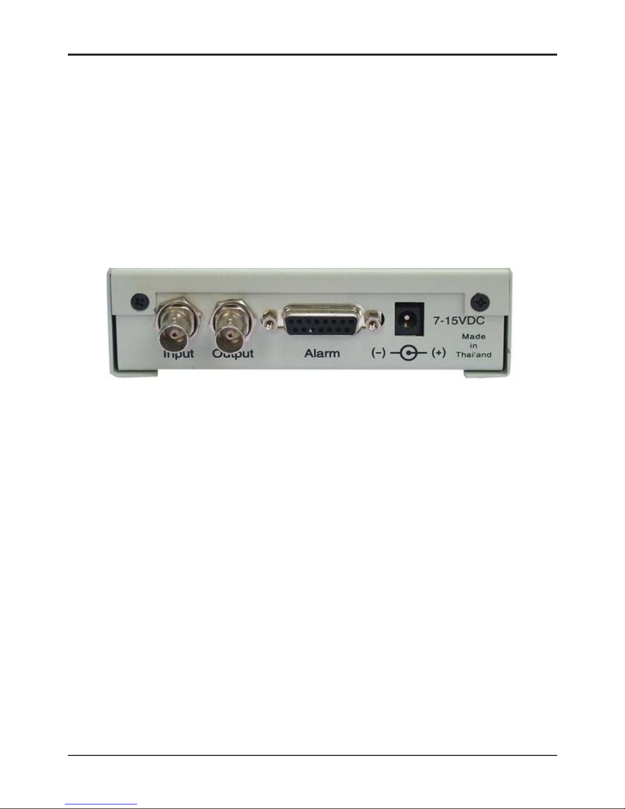
The video input and output are located on the rear of the unit. (see Figure 1). The video input connects to the video source
via the left BNC connector. The video output connects to a display , recording device, switcher , or other equipment via the
right BNC connector. Both the input and output are 1 V P-P into 75 ohms unbalanced EIA st andard RS-170A / NTSC or
CCIR / P AL video format. Improper input termination or looping will cause the video level to be too low and ef fect the
motion detection. Improper output termination will make the image or the video recording poor.
Connecting the Alarms
Alarm Output
The unit has one Form-C alarm output with normally open (N/O) and normally closed N/C configurations. It will produce
a closure and open whenever an alarm occurs. An alarm occurs when the DS1-PL detects motion or there is video loss
and the alarm has been enabled by pressing the ALARM ON-OFF button (red LED on). The contacts remain closed or
open for the duration programmed in the Relay Hold time. If the unit is set with a Relay Hold time of zero, no alarm will be
produced. The location of the alarm output connector is seen in Figure 1 and the pin-out configuration for the DB-15
connector is seen in T able 1. An alarm connector adapter is provided with the unit. All signals of the DB-15 connector can
be connected to this adapter via the screw terminals.
Some equipment may require a dry contact closure (normally open). Connect such equipment to the N/O and common
leads. For a normally closed alarm, connect between the N/C and common leads. There is no polarity; so these leads
may be swapped around or AC voltages used. Other equipment may require a closure to ground. In this case, a ground
connection will be provided on such equipment. Connect the common lead to ground and the N/O lead to the input of the
equipment. There is no voltage on the alarm connectors of the DS1-PL. No damage can be done by incorrect wiring
except exceeding the current or voltage rating.
Figure 1 : Video Input / Output
Page 10
10
Connecting
Alarm Connector DB-15
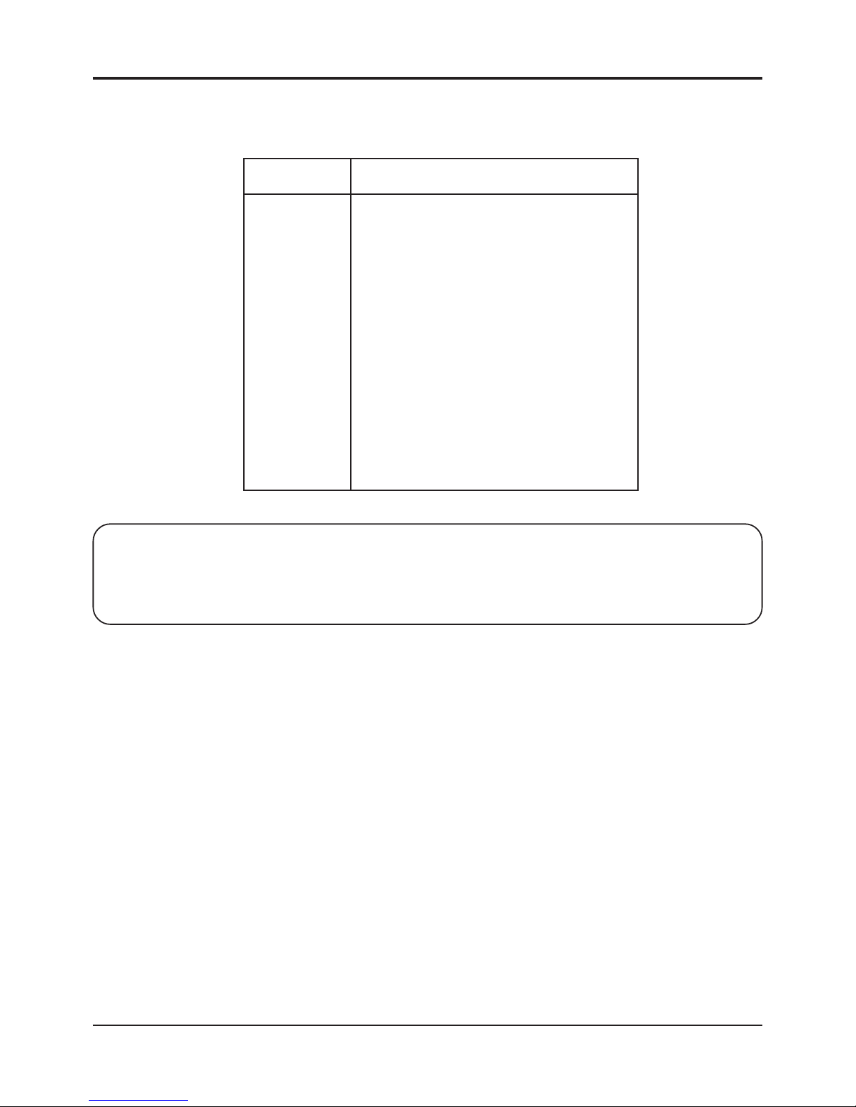
The DS1-PL has a female DB-15 Alarm connector with the following pin out for additional functions.
Pin # Function
1 Alarm Area A
2 Alarm Area B
3 Alarm Area C
4 Alarm Area D
5 Alarm Area E
6 Alarm Area F
7 Alarm Area G
8 Alarm Area H
9 N/C (Normally Closed) Universal Alarm
10 N/O (Normally Open) Universal Alarm
1 1 Com (Common) Universal Alarm
12 Ground
13 RS-232 Serial Output (TXD)
14 RS-232 Serial Input (RXD)
15 External Contact Input
Shield Ground
T able 1 : DB-15 Pin Out
Note
Pins 9-1 1 are Form C relay contact
Pins 1-8 are open collector transistor outputs (normally open)
Pin 15 is HiZ 100K ohm Max 5VDC input for Alarm or Day/Night mode
Day/Night Inputs
The Day/Night input switches settings from day settings to night when the unit receives a closure to ground on the
external contact input. If left open, day settings will be effective. An external timer, switch or photo cell can be used to
switch from day to night.
RS-232
The DS1-PL has an RS-232 interface for motion analysis and system configuration and operation that can be used in
conjunction with a PC or any RS-232C transmitting device. The DSVMD Windows based software gives complete
programming and operational command to the DS1-PL. The standard command set can be used to integrate control
functions within the users proprietary system for total system solution. See the Serial Protocol section on page 44 for the
complete command set.
Connecting the Power
The DS1-PL operates from a DC supply range from 7V to 15V DC. The power input connector, a standard 2.1mm x
5.5mm power jack, must have positive (+) on the center and negative (- or ground) on the outer shell. The unit is reverse
protected and correct polarity is indicated by the green Power LED being lit on the front panel.
For mobile operation a negative ground system is required. The unit may be operated from regular household power with
the appropriate adapter.
DIGITAL VIDEO MOTION DETECTOR
Page 11
11
DESCRIPTION
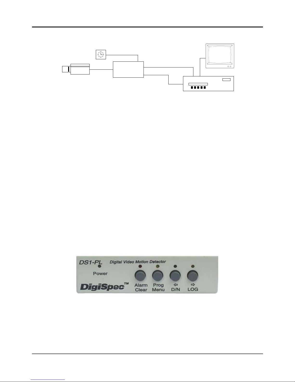
The DS1-PL is most commonly used for single channel systems requiring precision video motion detection. An alarm
output can be used to trip an event or time lapse recorder into real-time recording. An external timer can be used to toggle
the DS1-PL between Day and Night modes. Since the unit is 12V DC, it is perfect for covert surveillance applications. An
optional RS-232 remote communicating device can be used for programming and operation remotely.
Operation
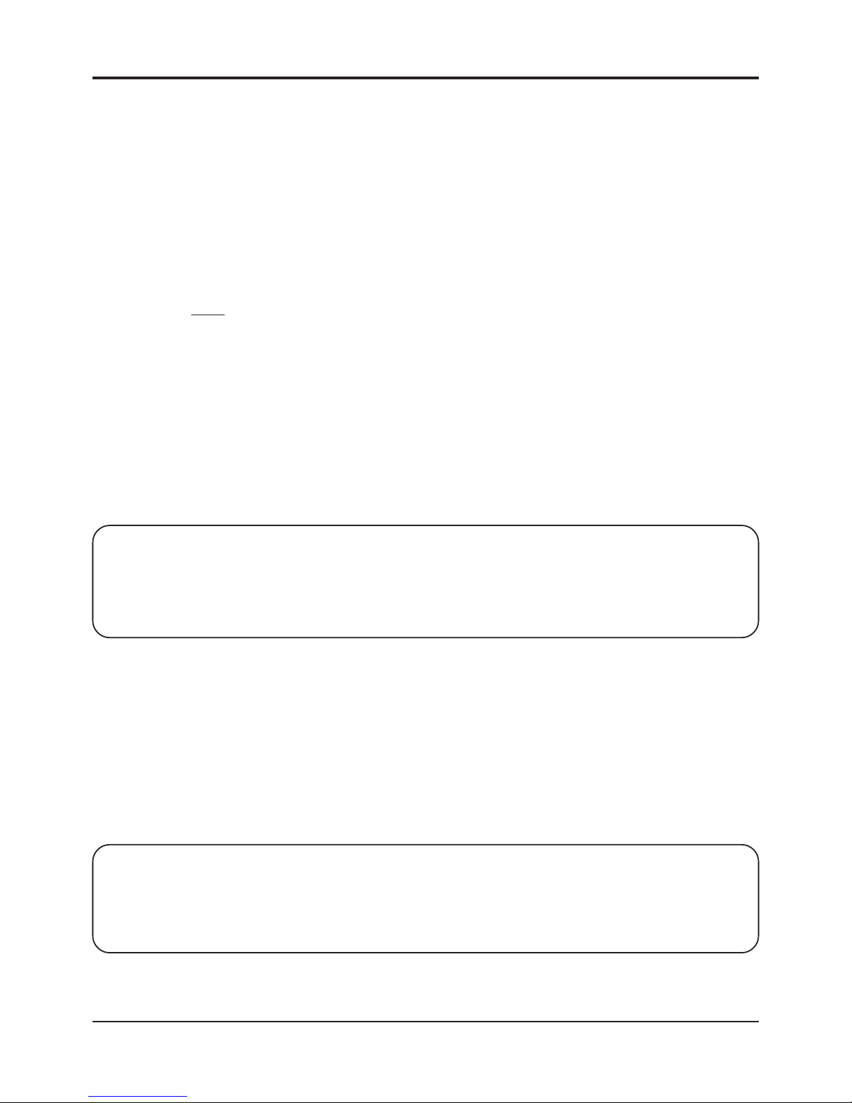
Four buttons on the front panel give full control of the unit. All settings are guided by on-screen prompt s. Simply press the
MENU button and follow the on-screen instructions.
The five LED’s indicate the state of the unit. The green Power LED indicates the unit is connected to the appropriate
power source. The red ALARM LED indicates the unit is armed when solid and alarmed when flashing. The yellow LED
above the MENU button indicates the unit is in the set-up mode. The green LED above the D/N button is lit when the unit
is in the day mode and off when in the night mode. The yellow LED above the LOG button is lit when the unit is displaying
the Log Page on-screen.
DAY/NIGHT INPUT
DS-1
MONITOR
ALM OUT 1
VID OUT 1
CAMERA
TIME-LAPSE RECORDER
EVENT RECORDER
Figure 2 : DS1-PL BASIC CONFIGURATION
Operation
DIGITAL VIDEO MOTION DETECTOR
Figure 3 : Button Operation
Page 12
12
Button Operation
The DS1-PL has 4 buttons, with associated LED’s, to provide all necessary functions.
There are four modes of operation of the DS1-PL
1) Normal Running Mode
2) Programming Mode
3) Day/Night Mode
4) Log Mode
1) Normal Running Mode Button Functions
In this mode, the DS1-PL is processing alarms (if enabled) and displaying the date-time (if enabled). The button functions
which are written
below each button, and are as follows
Alarm Button The Alarm button toggles between alarm enabled or disabled. When the alarm is enabled, the
DS1-PL will generate alarms whenever the motion detector qualifies valid motion. When the
alarm is disabled, all motion will be ignored. There are 2 indicators which display the alarm
enable/disable status.The red LED on the Alarm button will be lit during alarm enabled and will
be off during alarm disable. On-screen, the Alarm enabled status will display “A” if alarms are
enabled, and “a” if alarms are disabled.
If an alarm is active (i.e. the DS1-PL is generating an alarm) the red LED will be flashing.
Pressing the Alarm button will clear the alarm. Every time the Alarm button is pressed thereafter, alarms will toggle between enabled/ disabled again.
Operation
Note
The 3 On-Off timers will override the front panel alarm enable/disable toggle when their start or stop times
are reached. If you want to manually control the enabling from the front panel, you should disable all 3 On-Off
timers, in the Timers Menu.
Program Button The Program button starts the programming mode, which brings up the Main Menu on screen
with a blue back ground. The yellow LED will be lit while in this mode.
Day/Night Button The Day/Night button toggles between day and night settings. The DS1-PL can be programmed
for two indepen dent settings, called Day and Night, but these do not necessarily mean programming is required for Day and Night. It could be any time of the day or if there is any need
to switch between two programmed settings. There are 2 indicators which display the Day/
Night status. The green LED on the Day/Night button will be lit during Day settings and will be
off during night settings. On-screen, the Day/Night status will display “d” during day settings
and “n” during night settings.
DIGITAL VIDEO MOTION DETECTOR
Note
The day/night timer will override the front panel day/night button when The day/night timer will override the
front panel day/night button when their start or stop times are reached. If you want to manually control the day/ night
switching from the front panel, you should disable the day-night timer , in the T imers Menu.
Page 13

13
Log Button The Log button displays the Log Page on-screen on a green background. This displays the
most recent 160 alarm events, with their dates and times. Pressing the left/right buttons scrolls
forwards of backwards through the log. Pressing the Menu button prints the complete log.
Pressing the Clear button reverts back to normal running operation. The yellow LED will be lit
above this button while in the Log Display mode.
2) Programming Mode Button Functions
n this mode the DS1-PL is being set up. The yellow LED on the Menu button will be lit, and the screen will have a blue
background (except for zone pattern settings). The button functions are as follows:
Clear Button The Clear button is used to leave menu one level up or revert back to normal running operation
if current page is main menu page. If any changes were made, they will be saved to non-volatile
memory and these changes will take immediate effect on the operation of the DS1-PL.
Menu Button The Menu button steps through the programming options which are displayed on screen with
flashing prompts.Each time the menu button is pressed, the next prompt will flash indicating
that you may set this prompt. At the end of each menu p age, the last prompt will wrap around
to the top of the page (the first prompt).
Left Button The Left button is used to set the prompt by reducing its value if it is numeric, or sequencing
backwards if it is a text prompt. During zone pattern settings, the cursor will move to the left. If
you hold the Left button pressed for longer than a second, many of the settings will automatically change 3 times per second, or the zone pattern cursor will move left at a rate of 5 times
per second.
Right Button The Right button is used to set the prompt by increasing its value if it is numeric, or sequencing
forwards if it is a text prompt. During zone pattern settings, the cursor will move to the right. If
you hold the Right button pressed for longer than a second, many of the settings will automatically change 3 times per second, or the zone pattern cursor will move right at a rate of 5 times
per second.
3) Day/Night Mode
The DS1-PL has two sets of programming setups, one for Day and one for Night. The Green LED above the D/N button
when lit signifies the unit is in the Day mode. When the light is not lit the unit is in the Night mode.This light can be
controlled by the front panel button D/N, RS-232 command, or external input when selected as Day/Night input or the
internal timer.
4) Log Mode
The Log mode is constantly enabled and every event is recorded into the Log memory . When the Log memory is full to
its maximum of 160 events, the oldest event is discarded and the newest event replaces it. To enter the Log Mode, press
the LOG button on the front panel. The screen will have a green background and the latest logged events will be present
on the screen. Repeatedly press the LOG button to scroll through all the store logged events. Press the D/N button to
scroll the opposite direction through the Log File. To exit, press the Alarm button to return to normal operaton. The Log
mode can be entered by remote RS-232 operation also. The Log memory can not be erased unless you do a complete
system Master Reset which will set all the programmed settings to the factory defaults.
Operation
DIGITAL VIDEO MOTION DETECTOR
Page 14

14
On-Screen Display
On-Screen Display during Running Operation
During normal running mode, various information is overlaid onto the video picture. This is used as status information, to
be recorded to tape, or viewed by the person watching the monitor . Any or all this information may be turned on or off.
Refer to the On-Screen Data programming screen. There are 2 layout formats, S tacked and Series. This is set so that
image information is not obscured by this overlaid on-screen data. Stacked creates a tall and narrow display format.
Series creates a short and wide display format. The position of this block of information can further be positioned
anywhere on the screen by adjusting the horizontal and vertical position in the On-Screen Data programming screen.
Series Stacked
ABCDEFGHIJKLMNOPssssssss
MMM-DD-YY HH:MM:SSA A00d
Description
ABCDEFGH 16-character camera ID. Letters, numbers, and special characters
IJKLMNOP split into 2 blocks of 8 characters each if stacked.
ssssssss Status display of up to 8 areas as defined in the zone p attern setup.Indicates areas A-H from
left to right. Each of these 8 status indicators displays information pertaining the defined area,
and there are 5 symbols used to indicate the status
1) space Area is not enabled
2) . (dot) Area is enabled
3) -(dash) Area has motion
4) a - h Area has motion exceeding trigger level (a-h for respective area) Use this as
an indicator to assist in adjusting trigger level.
5) A - H Area has qualified alarm (A-H for respective area) Use this as an indicator to
assist in adjusting tracking time.
MMM-DD-YY Month (in 3 character alpha format, e.g. JAN,FEB,MAR...), Date, and Y ear . The sequence of
these can be changed at the Calendar mode prompt, in the On-Screen Data set-up menu, for
USA, Canadian, European, or Japanese formats.
HH:MM:SSA Hours, Minutes, Seconds, and AM/PM flag. The format can be changed in the Time mode
prompt to display 12-hour mode (with AM/PM), or 24-hour mode (military time). Whichever
mode chosen will also be used in the Timer mode menu screen.
A00d Alarm Enable Status, Alarm Counter , Day/Night S tatus.
Alarm Enable status will display “A” (upper case) when alarming is enabled (the red LED will
also be lit), or “a” (lower case) when alarming is disabled (the red LED will also be off). During
an alarm output condition, the status will change to a “ * ” (asterisk) and at the end of the alarm
output it will revert back to “A”.
The Alarm Counter counts up from 00 to 99 every time an alarm is generated. This is helpful in
searching a tape for the start of alarm events. Manually clearing an alarm (by pressing the
Alarm button) resets this counter to 00.
The Day/Night status will display “d” during Day mode settings, and “n” during Night mode
settings. The green LED on the Day/Night button will also be lit during Day mode and will be off
for Night mode.
DIGITAL VIDEO MOTION DETECTOR
A00d
ssssssss
ABCDEFGH
IJKLMNOP
MMM-DD-YY
HH:MM:SSA
Page 15

15
Programming
Video Loss
When video goes missing from the DS1-PL, a red warning background will be displayed with the message flashing
“VIDEO LOST” in large characters. If the date-time information is enabled (see the On-Screen Data programming menu),
the date and time when video went missing will be inserted under the “VIDEO LOST” message. This will warn an operator
of the video loss condition and give the time and date of this occurrence. If the video is recorded to tape, the date and
time will provide when the video loss had occurred.
After video has been restored, the DS1-PL checks it s validity , then does a “cold boot” which restores the DS1-PL to its
condition prior to video loss. See Section 9., Video Loss for programmig options for this function.
Programming the DS1-PL
T o start programming, press the Program button. The Main Menu p age will be displayed and the yellow LED will be lit on
the Program button.
Main Menu
Main Menu
1:MOTION DETECTION
2:ZONE PA TTERN MASK
3:ALARMS, RELA YS
4:TIMERS
5:ON-SCREEN DA TA
6:TITLER
7:DA TE-TIME
8:SERIAL PORT
9:VIDEO LOSS
There are 9 items on the Main Menu. They itemize the main categories for setting the DS1-PL. From this menu, you
branch to the menu page associated with each item where the setting is done.
Clear Button Leave menu one level up or revert back to normal running operation if current page is Main
Menu.
Menu Button Sequences down through the Main Menu prompts. When it gets to the bottom, it wraps
around to the top. An asterisk symbol highlight s the selected item.
Left Button or Selects the item in the Main Menu to program. The menu for the
Right Button selected item is called up.
DIGITAL VIDEO MOTION DETECTOR
Page 16

16
1. Motion Detection Menu
This is the most important set-up for the operation of the motion detector. It is used to adjust criteria for qualifying a valid
alarm. There are up to 8 areas which may be defined, and each of these areas has 3 criteria.
MOTION DETECTION: d
Mode...................Motion 8 Areas
__TrigL TrigH----SENS----TRACK__
A: ##### ##### ## #.# s
B: ##### ##### ## #.# s
C: ##### ##### ## #.# s
D: ##### ##### ## #.# s
E: ##### ##### ## #.# s
F: ##### ##### ## #.# s
G:##### ##### ## #.# s
H: ##### ##### ## #.# s
The top of the screen is the heading for this menu page, Motion Detection.
At the top right corner will be displayed “d” or “n” indicating you are programming the day
or Night settings. Remember to toggle the Day/Night mode (the Day/Night button) prior to
programming, to select the Day or Night settings.
The Mode Setting
The Mode setting defines the complexity of the DS1-PL, which is dependent on the scene from the camera. You may
analyze up to 8 areas in the image, setting the criteria for each. Or you may want to analyze the direction of moving
objects, etc. These are the options in the Mode setting.
Off This disables motion detection. However, alarms may still be triggered from an externals
source if you set the “External Input” prompt to “Alarms”.
Motion - 1 Area This sets up a single area to be analyzed for motion. For those familiar with the DS-1, it will
perform the same in this mode.
Motion - 2 Areas Multiple area analysis for perspective or difficult lighting situations. Each area can have
different criteria set to generate alarms. With 2 areas, one can be made foreground and the
other background.
Motion - 3 Areas Same as above with 3 definable areas.
Motion - 4 Areas Same as above with 4 definable areas. This mode may be used for the DS1-PL to process a
quad display .
Motion - 5 Areas Same as above with 5 definable areas.
Motion - 6 Areas Same as above with 6 definable areas.
Motion - 7 Areas Same as above with 7 definable areas.
Motion - 8 Areas Same as above with 8 (the maximum) definable areas.
Programming
DIGITAL VIDEO MOTION DETECTOR
Page 17

17
Programming
Direction A>B...G>H This causes the DS1-PL to analyze motion moving in a particular direction and to generate an
alarm when such an event occurs. Up to 8 areas are defined, being 4 “source” areas and 4
“destination” areas. Whenever an object moves from any “source” area to its associated “des
tination” area, an alarm is generated. Thus any direction can be defined by creating areas A and
B, C and D, E and F, G and H in the Zone Pattern setups.
The sequence of events to satisfy direction qualification are:
a) Motion in “source” area (A,C,E,G) above their trigger level with motion in “destination” area
below the trigger level....then within the tracking time of “source” and “destination” areas.
b) Motion in “destination” area (B,D,F ,H) above the trigger level.
This timing of motion between “source” and “destination” areas may also be used to qualify
motion by the speed of the moving object.
Motionless - 1 Area This causes the DS1-PL to analyze the defined area A, and if motion is less than the trigger
level for the duration set by the tracking time, then an alarm is generated. The primary applica
tion is for industrial machine-vision installations where you would typically watch machinery
such as a conveyor belt. If the conveyor belt stops moving, an alarm will be generated. Also,
this mode may be used to determine if an area has been deserted of people, being an abnormal
event.
Motionless - 8 Areas This causes the DS1-PL to analyze each defined area A-H, and if motion is less than the trigger
level for the duration set by their tracking times, then an alarm is generated for this area.
Anyalarm will also generate a global alarm output.
.
Museum Mode This mode causes the DS1-PL to check the amount of obscurity of areas defined by the Zone
Pattern menu. If an object is removed from the defined area for the duration set by the tracking
time, then an alarm is generated. T ypical applications include monitoring pictures in a museum
(hence Museum mode). Up to 8 works of art may be covered in this application.
NOTE
If museum mode is selected in operation . The track effect are Memory / S , Memory / A , Memory / AS will
not available if these functions have been used then VMD will disable it automatically
PTZ Compatible Mode This mode is a special mode to disable the video motion detection function while a Pan-to-
Zoom (PTZ) is in operation. Zones E,F,G and H are utilized for detection if the PTZ is in
motion. This is done by looking for motion in 3 out of 4 of these preset zones. The trigger ,
tracking, and sensistivity of these reference zones can be programmed by the user for
different applications. It is assumed that if 3 of the 4 zones have motion simulta neously
then the entire camera view is changing and motion detection is disabled. The “Alarm Reset
Time” is used here to time-out after the PTZ has stopped completely for video motion detec
tion functions to be initiated. Zones A-D can be programmed as normal for motion detection.
Upon detection of a moving PTZ image, the DS1-PL will display the text “PTZ” in the bottom
right-hand of the screen. This will indicate that the video motion detection is disabled and the
unit is in the PTZ mode. Af ter the PTZ has stopped and the relay hold time has expired,
normal video motion detection fuctions will resume. This text display can be turned off
by
turning off the St atus display via the on-screen programming.
DIGITAL VIDEO MOTION DETECTOR
Page 18

18
Programming
The Three Motion Detection Criteria
Each of the areas up to 8 as indicated by rows A-H is set independently for detecting motion. There are 3 motion
detection criteria for qualifying an alarm with respect to size, contrast from background, and duration of motion.
These 3 criteria, named Trigger Level, Sensitivity, and Tracking, are placed in 3 columns so they may be adjusted in a
tabular type format where values may be compared to each other to simplify set-up.
Different parts of the screen, depending on distance from the camera, lighting conditions, shadows, etc., may be defined
in separate areas using the zone pattern. Then the criteria should be adjusted to match the conditions to qualify an
alarm.
The Trigger Level Setting
The Trigger Level setting includes lower trigger & upper trigger are a threshold level, proportional to the size of the moving
objects. The motion of objects generate “delta” (which can be observed on the video image if the Trace effect is turned on
in the On-Screen Data menu page). The amount of delta is continuously compared to the trigger level, and an alarm is
qualified if the motion exceeds this trigger level threshold for a duration (as defined by the tracking time).
Objects further from the camera generate less delta than objects close up. So if the defined area is in the background,
you should reduce the trigger level.
There are 3 ways used to assist in setting up the Trigger Level.
Firstly, you may set the Status Display mode in the On-Screen Data menu to Area (A-H) Delta. This will display the
actual delta count in the on-screen status display . This number is then used to estimate the size of the moving objects
you want the motion detector to trigger. You then set the trigger level to that number. Each of the areas may be set
accordingly.
Secondly , you may set the Status Display mode in the On-Screen Dat a menu to Alarm Flags. This will display the status
information for all defined areas. After setting the trigger level, observe these status flags. If they change from a “-” (dash)
to a letter a-h without sufficient motion, then you should increase the trigger level for that area. If the status flag remains
a “-” (dash) with sufficient motion, then you should reduce the trigger level.
Thirdly , (and this comes with practice), you may calculate the desired trigger level. Each zone cell (there are 288 cells)
has 432 pixels, or points, that are calculated for delta. If you estimate the size of the object you want to trigger as a ratio
to the size of a zone cell and you multiply this by 432, this will give the number of pixels that the object will occupy in the
image. This will be the ideal trigger level for that size object. Keep in mind, not all pixels bound by the moving object will
generate “delta” pixels. This is because some moving objects will have some content of uniform shades of gray within the
object, so these pixels do not generate “delta”.
NOTE
The zones E-H are fixed and the defineable area cannot be changed, only the motion parameters. It is
recom mended that the velocity setting be set at least half that of the normal zones but no times set for longer
time than any detection zone.
DIGITAL VIDEO MOTION DETECTOR
Page 19

19
The Sensitivity Setting
The sensitivity setting is a contrast setting which discriminates the moving object from the background and also is a filter
to reduce the effects of noise on the video signal. The values in the sensitivity setting are 0-99, where 0 is the least
sensitive and 99 is the most sensitive. It is the level of
deviation of the grayscale required to generate a “delta” pixel. The
higher the sensitivity setting, the less the deviation required to generate “delta”. This may sound confusing, so just
remember, the higher the sensitivity setting, the more sensitive the video motion detector is to detecting moving object s.
Y ou may observe the “delta” effect on-screen by turning on the T race in the On-Screen Data
set-up menu. This is helpful
in setting up the sensitivity . If you want to reduce the ef fect of shadows triggering alarms, reduce the sensitivity, then
again observe the “delta” effect to see if shadows are generating “delta” pixels.
If you see false “delta”, which is normally produced by noise in the video signal, reduce the
sensitivity setting and again observe the “delta” effect to see if the false “delta” has been eliminated.
In low contrast images such as misty or foggy conditions where the moving object blends in closely with the background,
you will need to increase the sensitivity setting until sufficient “delta” is generated.
In most cases, however, the sensitivity can be lef t on 50%, the mid point.
The T racking Time Setting
The tracking time measures the duration of motion to qualify an alarm. Whenever the amount of motion exceeds the
trigger level, the defined areas are considered “triggered”. If this triggered condition remains for a certain time then an
alarm is qualified. This time is an adjustable setting and is called the tracking time because it is the time a triggered
object is tracked.
The tracking time is the best way to reduce false alarms in outdoors scenes. This is because most natural motion from
trees, insects, birds, etc. are erratic and their motion is not sustained long enough to qualify an alarm. A person however
has more “intent”, having a defined objective to move from point a to point b in a desired time. Objects moving with “intent”
can therefore be separated from objects with little or no “intent”.
Obviously when the object is further away from the camera it would take a longer time to traverse the image than if it were
in the foreground. This can be used as an advantage to qualify distant motion by increasing the tracking time.
Other atmospheric conditions such as lightning are of very short duration (generally under one second) and these can be
filtered out by keeping the tracking time to one second or more. If you do set the tracking time to 0, then effects such as
these will qualify an alarm. So if you do want to detect lightning for instance on your local golf course, set the tracking
time to 0.
Automobiles can cause alarms if they move in the defined area for the tracking time. If you do not want to trigger alarms
on automobiles but only people, then you will need to reduce the tracking time by compromise. Knowing that people
move slower than cars, estimate the minimum amount of time a person will move in the defined area and set the tracking
time accordingly . The tracking time is adjust able in 1/10th of a second increments from 0 seconds to 5 minutes.
2. Zone Pattern Mask Menu
The Zone Pattern Mask Menu is used to divide up the image into separate areas or to mask-out areas where motion is
analyzed or ignored.
There is a grid of 12 rows by 24 column zone cells. Any of these zone cells can be turned off (where motion will be
ignored) or assigned to one of 8 areas A-H.
Programming
DIGITAL VIDEO MOTION DETECTOR
Page 20

20
Programming
The Cursor
A cursor is displayed in a zone cell which is a flashing letter A-H depending on the area it is over . All other letters will not
be flashing. The cursor can be moved by pressing the Left or Right button keys. The cursor will change to a block while
it is moving to make it easier to see. As the cursor moves over areas, it will not change the area assignment s. It will
simply flash A-H depending on the area it is over . If it is over an undefined area (or off area) a dot will flash.
Button Functions
Clear Button Programming mode will terminate and the DS1-PL will return to Main Menu after saving the
zone pattern into non-volatile memory .
Menu Button The Area under the cursor will increase to the next area letter . If it was a B, it will become a C.
Each time the Menu button is pressed, the area assignment will increase one at a time until
area H (or the maximum possible). The next press will turn the area under the cursor off. If for
example, 3 areas are defined in the Motion Detection menu, then the zone under the cursor will
step A,B,C,off,A,B,C,off,A,B,C,off,.......etc.
DIGITAL VIDEO MOTION DETECTOR
AAAAAAAA BBB HHHHHH
AAAAAAAA BBBB HHHHH
BBBBB HHHH
CCCCCCCCC BBBBBB HHH
CCCCCCCCC HHH
CCCCCCCCCCCCCCCCCC HH
CCCCC HH
DDDDDD CCC HH
DDDDDDDD HH
EEEEEEEEEEEEEEEEEEEE H H
HHH
FFF GGGGGGGGGGGG HHHHH
FFF GGGGGGGGGGGGG HHHHH
Depending on how many areas are defined (A-H) in the Motion Detection set-up menu, this determines the maximum
number of areas that can be generated by the Zone Pattern Mask menu. If only 3 areas are defined for example, then
each zone cell can be either assigned OFF , A, B or C area. This area assigning will prevent areas greater than area C to
be assigned.
AAAAAAAA
AAAAAAAA
AAAAAAAA
AAAAAAAA
BBBBBBBB
BBBBBBBB
BBBBBBBB
BBBBBBBB
CCCCCCCCCCCCCCCCCCC
Page 21

21
Programming
Left Button This moves the cursor left one position. The cursor will flash the area letter assignment over the
new area. If you hold the left button for longer than a second, then the cursor will move at a rate
of 5 steps per second. While the cursor is moving it becomes a block to make it easier to see.
When the cursor reaches the left most position on the line, it will wrap around to the right most
position in the line above. If it is on the top line, it will wrap around to the bottom line.
Right Button This moves the cursor right one position. The cursor will flash the area letter assignment over
the new area. If you hold the right button for longer than a second, then the cursor will move at
a rate of 5 steps per second. While the cursor is moving it becomes a block to make it easier
to see. When the cursor reaches the right most position on the line it will wrap around to the left
most position in the line below. If it is on the bottom line, it will wrap around to the top line.
Menu+Left Button If you hold in the Menu button, then press or hold the left button, the cursor will move left (just
like the left button), except the area assignment under the cursor is dragged and copied as it
moves left. By doing this you can quickly paint in a contiguous area.
Menu+Right Button If you hold in the Menu button, then press or hold the right button, the cursor will move .
If during the zone pattern set-ups no buttons are pressed for longer than 2 seconds, then an alternative zone pattern
screen appears. You may at any time go back to the original zone pattern screen by pressing the Menu button. This
alternative zone pattern screen is used to quickly identify the area assignments. Its other purpose is to prevent the first
zone pattern screen from obscuring the image behind it.
What is shown on this zone pattern screen is the zone pattern grid of 24x12 except the present area A-H (under the
cursor) is replaced with flashing blocks. All other defined areas are replaced with dot s and undefined (or off) areas are
blank. The cursor will still indicate the present area as A-H with all other zone cells of the present area now being blocks.
Pressing the Left or Right buttons now flip through all areas, one at a time as blocks. This is an easy way to identify the
areas defined, especially if complex layouts have been generated. Keep an eye on the cursor, which will display the area
flipped.
The button functions for this zone pattern menu are as follows:
Clear Button Programming mode will terminate and the DS1-PL will return to Main Menu after saving the
zone pattern into non-volatile memory .
Menu Button The original zone pattern menu will be restored, with all area assignments displayed as A-H.
Left Button This flips the present area, as displayed by the cursor to the next area, which is now displayed
as flashing blocks. All other defined areas become dots.
Right Button This flips the present area, as displayed by the cursor to the next area, which is now displayed
as flashing blocks. All other defined areas become dots.
3. Alarms, Relays Menu
DIGITAL VIDEO MOTION DETECTOR
ALARMS: d
Buzzer....................................ALARM
Relay Output..........................ALARM
Relay State..............................NO
External Input........................OFF
Watchdog Timer ...................OFF
Entrance Delay.......................## s
Exit Delay...............................## s
Alarm Process ......................Time
Alarm Output Time.................## s
Alarm Reset Time..................## s
Page 22

22
Programming
The top of the screen is the heading for this menu page, Alarms.
At the top right corner will be displayed “d” or “n” indicating you are programming the day
or night settings. Remember to toggle the Day/Night mode (the Day/Night button) prior to
programming to select the day or night settings.
The Buzzer Setting
Options: OFF , ALARM
The DS1-PL has an internal piezo buzzer which can be turned off or beep during alarm or
motion conditions.
OFF The buzzer will not sound under any conditions. If you want the DS1-PL to be “silent”, be sure
to turn the buzzer mode setting to OFF.
ALARM The buzzer will sound whenever an alarm output is generated by the DS1-PL. That is when
motion has been qualified to generate an alarm. The buzzer will sound for the duration of the
Alarm Output Time Setting (see below). This is the actual time an alarm contact is generated.
Relay Output Setting
Options: OFF , ALARM, PRETRIG , TIMER1, TIMER2, TIMER3, DA Y/NGT
The universal form-C (NO, COM, NC) Alarm Relay generates cont act closure and opening.
These contacts are connected to the device such as a video recorder or alarm distribution
panel. There are 3 “dry” contacts, normally-open, common, and normally closed, which are
accessed by the back panel connector . Refer to the back panel diagram for these connection
points.
The Alarm Relay can activate under various programmed conditions:
OFF The Relay will remain inactive under all conditions. Even if the DS1-PL qualifies an
alarm, no operation of the relay will take place.
ALARM The Relay will activate whenever an alarm is qualified by the DS1-PL. The Alarm Relay
remains activated for the duration of the Alarm Output Time Setting (see below). This is the
most common for the alarm relay output mode setting.
PRETRIG The Relay will activate before an alarm is fully qualified. Whenever motion exceeds the
trigger level in any defined area, the Relay will activate. This may be used as an
early
warning alarm output, to either warn an operator of a potential pending alarm or to start a
recorder recording early, so that more alarmed foot age may be recorded to tape.
TIMER1,2,3 The Relay will activate between the Start and S top times of any of the 3 on-of f timers.
This may be used to turn equipment on and off such as lights, at different times of the day.
DA Y/NIGHT The Relay will activate following the Day/Night mode of the DS1-PL. The relay will be
active during Night mode and inactive during Day mode. The toggling of the DS1-PL ’s Day/
Night mode can be done from the front panel, from the Day/Night timer if enabled, from an
external input (see below), or from a serial RS-232 command.
DIGITAL VIDEO MOTION DETECTOR
Page 23

23
Programming
External Input Setting
Options: OFF, ALM-AND, ALM-OR, ENABLE, DISABLE, DA Y/NGT, CAP REF
An input signal to the DS1-PL may be used to control the DS1-PL in various ways. A closure to ground activates this
signal, so it may be in the form of a loop-closure switch to ground, a TTL level low , or a closure to ground from an external
device (in this case both the DS1-PL’ s ground and the equipment’s ground needs to be commoned).
The various modes of this external input contact are set with this prompt to provide the following actions:
OFF The DS1-PL takes no action on the external input whether it be open or closed to ground.
ALM-AND The DS1-PL combines alarms from external equipment (or another DS1-PL) such that an
alarm is output when the DS1-PL qualifies an alarm
and the external equipment generates an
alarm. This is used as a
redundancy-verification system to double-check the validity of an
alarm. This mode may also be used as a 3D-triangulation method of detecting motion in 3D
space. If 2 DS1-PL ’s are used with their cameras looking perpendicularly at a scene with the
first DS1-PL’ s alarm output connected to the External Input of the second DS1-PL, then the
second DS1-PL will generate an alarm whenever motion occurs at the intersection of both
DS1-PL’ s zoned areas.
ALM-OR The DS1-PL combines alarms from external equipment (or another DS1-PL) such that an
alarm is output when the DS1-PL qualifies an alarm
or the external equipment generates an
alarm. This is used as a
redundancy-safety system, to generate an alarm condition, from
one of many events. If 2 DS1-PLs are used with the first DS1-PL ’s alarm output connected to
the External Input of the second DS1-PL, then the second DS1-PL will generate an alarm
whenever qualified motion occurs from either camera. This can be used in heavy industry
where stamping presses need to be turned off whenever a person moves into any area where
they may be harmed.
ENABLE The DS1-PL is enabled whenever this signal is active (a closure to ground). You may use this
to gate the operation of the DS1-PL on and off. For example, this may be used to enable the
DS1-PL only when a door is closed by using a door contact which makes a contact closure
when the door is closed.
DISABLE The DS1-PL is disabled whenever this signal is active (a closure to ground). Y ou may use
this to gate the operation of the DS1-PL on and off. For example, this may be used with a
PTZ controller to disable the DS1-PL whenever the camera moves, then enable the DS1-PL
again when the camera stops moving.
DAY/NGT The DS1-PL can be switched between the day and night settings with the External Input.
When the External Input is active (closure to ground), the DS1-PL will switch to the Night
mode settings, and when this signal becomes inactive the DS1-PL will switch to the Day
mode settings.
CAP REF In the Museum mode, the DS1-PL compares the live image from the camera to a freeze
frame image stored in memory to determine the obscurity of the areas it is processing.
Normally this freeze frame reference image is captured automatically at the end of the
programming of the DS1-PL. Y ou may want to capture this reference image at any time later ,
you can do this by setting this mode. The reference image will be captured when the Exter
nal Input makes a closure to ground.
DIGITAL VIDEO MOTION DETECTOR
Page 24

24
Watchdog Timer
Options: ON, OFF
The internal watchdog timer is in continuous operation whether this setting is ON or OFF . If for some reason the uP stops
for more than 250ms, the internal counter is automatically timed-out and issues a reset to the uP to continue operation.
When this option is selected ON, the watchdog timer signal is output to Zone Alarm H. This output is continuously
toggled ON and OFF at a period of 250ms. If for some reason this signal is not periodic, the uP has ceased to operate
from a hardware failure. When this option is set OFF, the watchdog output is not sent to Zone Alarm H and this alarm
function is normal.
Entrance Delay Setting
Options: 0-99 seconds
The entrance delay is the delay which occurs the first time the DS1-PL qualifies an alarm (after being manually enabled)
to the time it generates its first alarm output. This will give the user the opportunity to enter the premises without
generating an alarm. Most domestic alarm systems have this feature. The Entrance Delay can be programmed to
between 0 and 99 seconds. If it is set to 0, then the DS1-PL will generate an alarm immediately after the the first motion
has been qualified.
Exit Delay Setting
Options: 0-99 seconds
The exit delay is the delay which occurs after the DS1-PL has been manually enabled (by pressing the Alarm button) to
the time it starts processing motion to qualify an alarm. This will give the user the opportunity to exit the premises before
an alarm is generated. Most domestic alarm systems have this feature. The Exit Delay can be programmed to between
0 and 99 seconds. If it is set to 0, then the DS1-PL will start to process alarms immediately after the DS1-PL has been
enabled.
Alarm Process
Options:Time or Retrigger
The Time mode is defined as a fixed period of time from when the alarm is initiated. After the programmed time period,
the alarm is stopped and can not be reset until the Alarm Reset time has elap sed. If multiple alarms occur within the
Time mode, they are ingored and the time starts from the initiation of the first alarm.
The Retrigger mode starts the programmable time from the last alarm occurance within the dwell period. If an alarm
occurs and is reset within the programmed alarm time and a new alarm occurs, the programmed alarm time is reset and
the process occurs indefinitely until no alarms occur within the programmed time period.
Alarm Output Time Setting
Options: Man 0-99 seconds
The Alarm Output T ime is the time an alarm is actively output to the relay contact s. The buzzer will also sound for this
duration if it has been set to Alarm mode. The alarm will stay active for this time and no further processing of motion will
take place until it has timed-out. If motion continues when it has timed-out, the alarm output time will be extended to the
point where motion no longer exceeds the trigger level set. One second should be an adequate setting in most cases
because video recorders have their own recording time setting, and video switchers and matrix switchers have their own
alarm dwell time settings. If the Alarm Output Time is set to Man ( Manual ). Alarms will generated following VMD.
Programming
DIGITAL VIDEO MOTION DETECTOR
Page 25

25
Alarm Reset Time Setting
Options: 0-99 seconds
This is the minimum time between alarms generated by the DS1-PL. This is a means to stretch out alarm events. For
instance, if you are using the DS1-PL to trigger a video printer , you want one picture when an alarm event occurs but not
hundreds of pictures of each event. At the end of the alarm output when the relay drops out, the DS1-PL will reset itself
and stay reset for this duration before the next alarm is qualified.
4. Timers Menu
The DS1-PL has 3 independent on-off timers used to enable/disable motion detection, and one day/night timer to toggle
between 2 banks of user’s settings called Day and Night.
TIMERS:
Tmr1: OFF HH:MMA - HH:MMA
Tmr2: OFF HH:MMA - HH:MMA
Tmr3: OFF HH:MMA - HH:MMA
Day/Night Timers.......................OFF
Day.....................................HH:MMA
Night ..................................HH:MMA
The top of the screen is the heading for this menu page, Timers.
The 3 On-Off Timer Settings
Each of the 3 timers are set independently . Each has a mode and a S t art and Stop time.
The mode, which is the first setting (on the left), determines if the timer is turned on and which day(s) of the week the
timer will be active. The DS1-PL alarm will be enabled on this day(s) between the set S tart and Stop time.
Mode Options: OFF, SUN, MON, TUE, WED, THU, FRI, SAT, M-F, M-S, S-S, ALL
This selects if the timer is either Off, is a specific day of the week (Sunday through Saturday), or is a combination of
days.
M-F is Monday through Friday
M-S is Monday through Saturday
S-S is Saturday and Sunday (weekend)
ALL is every day of the week
Programming
DIGITAL VIDEO MOTION DETECTOR
Page 26
26
Start and Stop Times
On the day(s) of the week selected, the DS1-PL will be made enabled during the Start and Stop times. The first time,
displayed as HH:MMA, is the hour, minute, and AM/PM that the DS1-PL will become enabled. This is the St art time.
The second time, displayed as HH:MMA, is the hour, minute, and AM/PM that the DS1-PL will become disabled. This
is the Stop time. If the S top time is earlier than the S tart time, then the DS1-PL will become disabled on the following day .
Programming
By combining up to 3 On-Off timers, many combinations of enabling/disabling of the DS1-PL can be achieved. The times
and days of the timers may be seperated or may even be overlapped. When more than one timer is on, then motion
detection will be enabled when any timer is between its St art and Stop time. The motion detector will be disabled when
all timers have reached their stop times. The examples that follow will show how this works.
Timer Examples
Example 1
Enable motion detection every day between 8 AM and 5 PM.
Tmr1: ALL 08:00A - 05:00P
Tmr2: OFF
Tmr3: OFF
Example 2
Enable motion detection every day between 7:30 PM and 8:45 AM.
Tmr1: ALL 07:30P - 08:45A
Tmr2: OFF
Tmr3: OFF
Example 3
Enable motion detection every weekday in the mornings between 6 AM and 6:30 AM,and in the
afternoons between 4:30 PM an 5:10 PM.
Tmr1: M-F 06:00A - 06:30A
Tmr2: M-F 04:30P - 05:10P
Tmr3: OFF
DIGITAL VIDEO MOTION DETECTOR
For example:
Tmr1: TUE 4:00P - 8:00A will enable the DS1-PL from 4 PM on Tuesday to 8 AM on Wednesday.
Note
If a timer is turned Off, then the S tart and S top times will have no effect.
Page 27
27
Programming
Example 4
Enable motion detection every Saturday between 9 AM and 4 PM, every Sunday between noon and
3 PM, and every weekday between 7 AM and 6 PM.
Tmr1: SAT 09:00A - 04:00P
Tmr2: SUN 12:00P - 03:00P
Tmr3: M-F 07:00A - 06:00P
Example 5
Enable motion all Friday .
Tmr1: FRI 12:00A - 1 1:59P
Tmr2: OFF
Tmr3: OFF
Example 6
Enable motion detection every weekday between 9 PM and 5:30 AM and every weekend between
7 PM an 10 PM.
Tmr1: M-F 09:00P - 05:30A
Tmr2: S-S 07:00P - 10:00P
Tmr3: OFF
Example 7
Enable motion detection on Tuesday at 7 AM, at 8 AM, and at 9 AM for 5 minutes each.
Tmr1: TUE 07:00A - 07:05A
Tmr2: TUE 08:00A - 08:05A
Tmr3: TUE 09:00A - 09:05A
Example 8
Enable motion detection every day between 6 AM and 7:30 PM except Fridays which should be
between 5:30 AM an 9 PM.
Tmr1: ALL 06:00A - 07:30P
Tmr2: FR I 05:30A - 09:00P
Tmr3: OFF
DIGITAL VIDEO MOTION DETECTOR
Page 28

28
The on-off timers are a way to fully automate the generation of alarms. Once the timers have been set, the DS1-PL needs
no further intervention. If you do not want an automated (by time) DS1-PL, then be sure to turn all the timers off. In this
way , you can enable or disable alarming from the front panel using the alarm button as an enable/disable toggle.
you are using a timer (or timers) to enable/disable the motion detector, you may still override the enable/disable function
from the front panel, but at the next Start or S top time of the timer , the timer will take control again of enabling/disabling.
After you set the timers you may wish to manually disable motion detection from the front panel, then walk away and let
the timers take control from that point. Y ou may observe the timers kicking in and out of operation by watching the st atus
indicators. When the DS1-PL is enabled, the red LED will be lit above the Alarm button. Also, the Alarm status onscreen will display “A” (uppercase) when enabled, and “a” (lowercase) when disabled.
The Day/Night Timer Settings
The Day and Night modes of the DS1-PL are 2 independent banks of the user’s settings which contain all the settings of
the DS1-PL where you may have different zone patterns, sensitivities, and buzzer on/off, etc.
The purpose is to quickly switch between these settings for different conditions. It will most likely used for switching
between motion criteria for detecting motion in the day and at night. However, the day and night settings may be used at
any time of the day or night when the user wants to switch between 2 programmed banks of settings.
The Day/Night timer can be used to automate this switching between day and night settings. There are 2 modes, On and
Off. Turn the Day/Night timer On if you need to use it and Off if you want to manually switch between Day/Night modes
by using the Day/Night toggle button on the front panel.
There are 2 times that are set. The first is the Day switchover time and the second is the Night switchover time. The
format is the same as the On-Off timers: HH:MMA This sets the hours, minutes, and AM/PM for the Day or Night
switchover times.
At the time of the day’s switchover time, the DS1-PL will use the “day” settings. Also, the green LED will be lit and the
day/night status indicator on screen will display “d”.
At the time of the night’s switchover time, the DS1-PL will use the “night” settings. Also, the green LED will be of f and the
day/night status indicator on-screen will display “n”. The Day/Night timer works independently of the 3 On-Off timers. So
while the On-Off timers are enabling/disabling the motion detection, the day/Night timer will load the Day or Night
settings.
Y ou may use the Day/Night timer as a 4th On-Off timer if you need by turning on motion in the Day settings (mode setting
in the Motion Detection menu), and turning it off at night, or visa versa.
DIGITAL VIDEO MOTION DETECTOR
Programming
Page 29

29
Programming
5. On Screen Data Menu
The DS1-PL displays overlaid on the video image various information to be observed or recorded to tape. It is used mainly
as status information pertaining to the image being analyzed. There are various items such as date and time and camera
titler, or black screen or “delta” ef fects, and each of these may be turned on or off or placed in various modes of display .
None of these settings affect in any way the performance of the motion detection. They are only there for the benefit of
enhancing the information provided to the user.
DIGITAL VIDEO MOTION DETECTOR
ON SCREEN: d
Display Layout......................SERIES
Position...........................H: 03 V: 20
Status........................ALARM FLAGS
Calendar Display...........MMM-DD-YY
Time Display.........................12 Hour
Trace Effect..........................MOTION
Video Blackout...........................OFF
Titler Display................................ON
The top of the screen is the heading for this menu page, On Screen.
At the top right corner will be displayed “d” or “n” indicating you are programming the day
or night settings. Remember to toggle the Day/Night mode (the Day/Night button) prior to
programming to select the day or night settings.
The Layout Setting
Options: OFF , ST ACKED, SERIES
The DS1-PL has 2 dif ferent ways the on-screen information is displayed (such as date, time, titler , etc). This is set so
that the image behind it is not obscured.
OFF No on-screen information is displayed. This is a way to globally turn all the on-screen
information off so that the camera’s video is all that is seen on the monitor .
ST ACKED The on-screen information is displayed in a tall and narrow format of up to 5 lines of text high
and of 9 characters across.
SERIES The on-screen information is displayed in a short and wide format of up to 2 lines high and of
24 characters across.
The Position Settings
Options: Horizontal: 1-12, V ertical: 1-22 (NTSC) or 1-27 (PAL)
The on-screen information can be shifted to any part of the screen by setting the values in the horizontal and vertical
settings.
Horizontal is the left to right positioning of the display. The higher the number, the more to the right the
Vertical is the top to bottom positioning of the display . The higher the number, the more to the bottom the display will be.
Page 30

30
Typical settings are:
Horizontal: 3, V ertical: 3 (for the top left corner)
Horizontal: 3, V ertical: 20 (for the bottom left corner)
Lining up the on-screen display to the top or bottom right corners depends on the stacked or series settings because this
defines the shape of the layout information.
The Status Setting
Options: OFF , AREA # DELTA, ALL DEL TA, ALARM FLAGS
The DS1-PL has 2 different ways the on screen information is displayed (such as date, time, titler ,etc). This is set so that
the image behind it is not obscured.
OFF No on screen status information is displayed. This turns of the 8-character position status
indicators, as well as the alarm status display , alarm counter display, and day/night status
display.
AREA # DELTA The delta for a specific area A-H can be displayed. This indicates the number of pixels which
have moved in that area, as defined in the zone pattern setups. The higher the number , the
larger is the moving object. No motion will indicate 0 (zero pixels moving). You may use this
setting to assist in setting up the trigger level for a specific area.
ALL DELTA The delta for all defined areas A-H can be displayed. This indicates the number of pixels which
have moved in all defined areas. The higher the number , the larger is the moving object. Any
motion in any area will generate a number indicating the number of pixels.
ALARM FLAGS This is probably the most informative status display . It indicates the st atus of eacharea by
using symbols to indicate their status. For each area A-H:
1) a dot represents no motion (or even noise) is present.
2) a dash represents any motion not exceeding the trigger level.
3) a lower case letter (a-h) represents motion exceeding the trigger level.
4) an upper case letter (A-H) represents motion exceeding the trigger level for a sustained
period of time as set in the tracking time setting. This also shows when an alarm is qualified.
The DS1-PL will generate an alarm output condition if any upper case (area) is displayed.
The Calendar Display Setting
Options: OFF , MMM-DD-YY, YY -MMM-DD, DD-MMM-YY
The month, date, and year display may be turned off or displayed in various international modes which change the order
of this data. This setting is only for on-screen information, so does not affect the internal clock used for timers and
logging functions. The calendar format is used for date-time generation and the same setting is also used in the Log
display.
OFF No on-screen calendar information is displayed.
MMM-DD-YY Month, then date, then year (USA).
YY-MMM-DD Y ear , then month, then date (Canada, Japan).
DD-MMM-YY Date, then month, then year ( Europe, Asia).
Programming
DIGITAL VIDEO MOTION DETECTOR
Page 31

31
The Time Display Setting
Options: OFF , 12 hour , 24 hour
The hours, minutes, and seconds display may be turned off or displayed in 2 formats. This setting is only for on-screen
information so does not affect the internal clock used for timers and logging functions. The time format is used for datetime generation and the same setting is also used in the Log display as well as the setting page for timers.
OFF: No on-screen time information is displayed.
12 hour Hours (1-12) , minutes, seconds, and AM/PM st atus (A or P).
24 hour Hours (00-23) , minutes, seconds
The Trace Effect Setting
Options: OFF, MOTION, MEMORY , MEMOR Y/F, MEMORY/S, MEMORY/A, MEMORY/AS
The DS1-PL calculates motion on the pixel level. Each pixel is calculated for motion independently. Any pixel that
exceeds the sensitivity threshold can be displayed on-screen. These appear as little highlighted dots called the “delta”
display or “trace effect”.
These dots appear to surround moving objects or follow the trajectory of moving objects when they are accumulated in
the “memory” modes.
OFF: No on-screen time trace effect is displayed.
Motion Trace effect continuously updates frame by frame, normally seen as high lighted pixels
surrounding moving objects.
Memory Trace effect is accumulated, which highlights areas in the image where motion has taken
place since last cleared. The trace memory may be cleared manually by pressing the
Alarm button or automatically at the end of the alarm timeout. If the alarm is disabled, the
trace will continue accumulating. This feature is used to display the history of past motion
activity or display the trajectory of moving objects. The trace memory highlights the pixels
affected so the image becomes brighter in these areas, so the image is still seen.
Memory/F Trace effect, same as above, except flashed on and off the screen 2 times per second. This
may be used when the trace memory obscures the background video image too much.
Memory/S Same as Memory Function, but this function will show trace effect in strobe effect at 2 Hz.
Memory/A Same as Memory Function but the memory on-screen starts after the motion alarm has
occured.
Memory/AS This is the same as Memory/S but the memory strobe mode starts after the motion alarm
has occured.
Programming
DIGITAL VIDEO MOTION DETECTOR
Note
Memory /S, Memory /A, and Memory / AS are not available in museum mode . If these function have been
seleceted.The VMD will disable it automatically .
Page 32
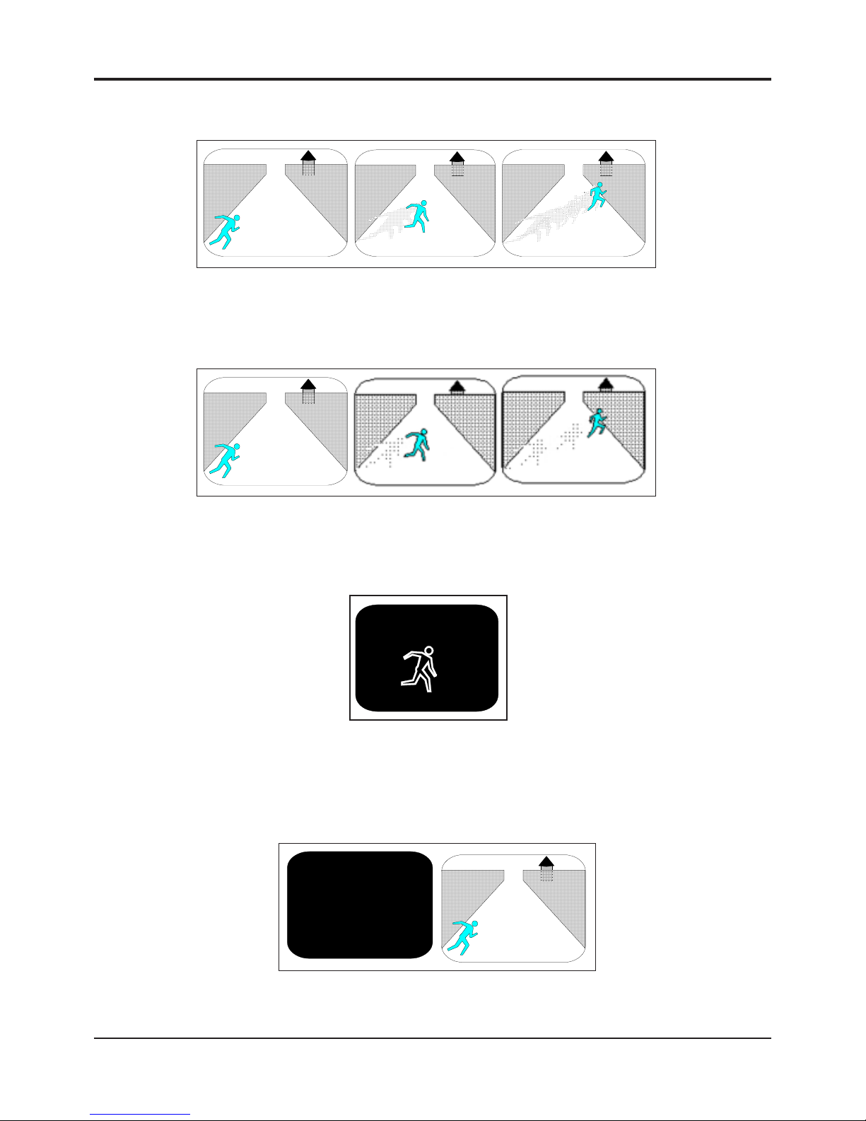
32
Programming
TRACE "MEMORY"
Figure 4 : TRACE "MEMORY"
BLACKOUT "ON" & TRACE "ON"
Figure 6 : BLACKOUT "ON" & TRACE "ON"
BLACKOUT "AUTO"
Figure 7 : BLACKOUT "AUTO"
TRACE "MEMORY"
Figure 5 : TRACE "MEMORY"
DIGITAL VIDEO MOTION DETECTOR
Page 33

33
Programming
DIGITAL VIDEO MOTION DETECTOR
The Video Blackout Setting
This setting allows for the entire screen to be black so no video view of the camera can be seen. If the trace motion is
enabled, you will see the white trace outline on the black video background.
Options: OFF , ON, AUTO, AUTO RST
OFF Normal video screen operation.
ON The entire video screen will be black with the exception of the on-screen data and the trace
effect if enabled.
AUTO The entire video screen will be black with the exception of the on-screen data and the trace
effect if enabled until an alarm is detected. When this occurs the video screen will switch
back to the normal video view. The normal view will remain until manual alarm botton is reset
and set and gain.
AUTO RST When alarm is set will turn on video. When alarm is reset will turn on blackout.
The Titler Display Setting
Options: OFF , ON
The 16-character camera titler may be turned on or off. The titler may also be turned off by making all the characters a
“space”, but this is an easier way to do it.
OFF No on-screen camera titler is displayed.
ON The camera titler is displayed. A dif ferent titler message may be used for day and night settings
to indicate different conditions or to identify the operators name or what the camera is looking
at, etc.
6. Camera Titler Menu
The Camera Titler is a means of writing a message onto the video image, to identify the camera, or for any other
information you wish to put there. It is a text message of 16 character positions which may consist of any mix of alpha
characters (A-Z), numeric characters (0-9), and special characters (such as periods, commas, spaces, etc.).
The titling information along with the Date and Time information is recorded on the tape. It is used mainly as status
information pertaining to the image being analyzed. There are various items such as date and time, and camera titler , or
black screen or “delta” effects, and each of these may be turned on or off or placed in various modes of display . None of
these settings affect in any way the performance of the motion detection. They are only there for the benefit of enhancing
the information provided to the user.
TITLER: d
DIGI-SPEC DS-1PL
: SP ACE CHARACTER
The top of the screen is the heading for this menu page, T itler .
At the top right corner will be displayed “d” or “n” indicating you are programming the day or night settings. Remember to
toggle the Day/Night mode (the Day/Night button) prior to programming to select the day or night settings.
Page 34

34
DIGITAL VIDEO MOTION DETECTOR
Programming
The Titler Settings
Press the MENU button to sequence through all 16 positions. If you overstep a position, the prompt will wrap around from
the end to the beginning again. A flashing prompt will indicate which character is being set. Press the left or right buttons
to sequence forwards or backwards through all available characters until the desired character is reached. A space
character is displayed as a flashing block.
7. Date-Time Menu
The Date-Time Menu is used to set the clock of the DS1-PL. The clock is used for the following functions:
1) On-Screen Date-Time Generator (this may be turned off in the On-Screen menu)
2) On-Off Timers
3) Day/Night Timer
4) Alarm Logging
The clock will keep time if the DS1-PL is powered down for as many as 3 days by using power from an internal
“SuperCap”. You will need to set the clock if the unit is powered down for longer than this period. The clock should
maintain accuracy within less than 7 seconds per month depending on the ambient temperature.
The top of the screen is the heading for this menu page, Date-Time.
In this menu, the preset date and time information, alarm counter, and day of week is displayed. This screen can be
called up independently of day/night settings.
The Date Time Settings
Clearing The Alarm Counter
There are 9 prompts associated with this set-up screen and they sequence in the order displayed:
MMM Month displayed as (JAN, FEB, MAR,...... NOV, DEC)
DD Date (1-31)
YY Year (00-99). Note: the year 2000 is 00
HH Hours (1-12 with AM/PM, or 00-23, depending on 12/24 format chosen on the On-Screen menu
set-up)
MM Minutes (00-59)
SS Seconds (00-59)
A00 Alarm Counter (00-99) -Can clear this number by selecting and setting to 00
DAY Day of the week (SUN, MON, TUE,...... FRI, SA T) requires setting if you use the timers.
DA TE-TIME:
APR-30-96 10:22:47A A00
DA Y : FRI
DST : OFF
Page 35

35
DIGITAL VIDEO MOTION DETECTOR
Programming
DST Daylight Saving Time (OFF, USA, CANADA, AUSTRALIA, T ASMANIA). This mode automatically
adjusts for daylight saving time, a 1-hour decrease in the Fall and a 1-hour increase in the Spring.
USA - Second Sunday of March after 2:00 a.m. (+1 hr)
- First Sunday of November after 2:00 a.m. (-1 hr)
Canada - Second Sunday of March after 2:00 a.m. (+1 hr)
- First Sunday of November after 2:00 a.m. (-1 hr)
Australia - Last Sunday of October after 2:00 a.m. (+1 hr)
- Last Sunday of March after 3:00 a.m. (-1 hr)
Tasmania - Last Sunday of October after 2:00 a.m. (+1 hr)
- Last Sunday of March after 3:00 a.m. (-1 hr)
8. Serial Port Menu
The DS1-PL has a RS-232 interface to receive and transmit data from a PC or a serial printer or any other peripheral
device that will accept RS-232 data.
The serial input may be used to set up the DS1-PL to alter settings. Software named PLSETUP.EXE will run on a PC to
configure the DS1-PL remotely from the PC. Refer to the Serial Protocol Section for details.
The serial output generates various status information which may be captured on a PC or printed to a serial printer . A
serial/parallel converter box is required if the printer has a parallel (Centronics) interface.
The pins on the female DB-15 connector used for serial communication are:
12 ----- Ground (Common)
13 ----- Transmit Data (Output)
14 ----- Receive Data (Input)
SERIAL: d
Serial Mode....................4800,N,8,1
Unit Input Address......................00
Output Rate................PER ALARM
Output Data............ALARM FLAGS
TCP/IP 192.168.000.100
Text Ouput Mode......................--->
Serial Input..............................OFF
The top of the screen is the heading for this menu page, Serial Port.
At the top right corner will be displayed “d” or “n” indicating you are programming the day or night settings. Remember
to toggle the Day/Night mode (the Day/Night button) prior to programming to select the day or night settings. The baud
rate and address are the same for the Day mode and Night mode. If you change in one mode, the other will change
automatically.
The Mode Setting
Options: 1200, 2400, 4800, 9600 ,19200, 28800
These are the baud rates available for communication with the DS1-PL. The mode is fixed at 8 data bits, no p arity , and
1 stop bit. The DS1-PL may , however , receive 2 or more stop bit s.
Page 36

36
The Address Setting
This sets the address of the unit for the serial communications. This allows the RS-232 data to all units to be in parallel
and only accept commands if the correct address is selected.
Options: 0-127
The Output Rate Setting
Options: OFF , PER ALARM, CONTINUOUS
The data rate setting configures the rate at which the DS1-PL outputs data.
OFF No serial data is transmitted by the DS1-PL. Serial data may still be received.
PER ALARM The serial data is sent at the start of each alarm generated by the DS1-PL, so data may be
“stretched out” over time by increasing the Alarm Output T ime setting in the Alarms menu.
CONTINUOUS The serial data is sent each and every frame of video, which consists of single bytes or packets
of information every 1/30th second in NTSC (1/25th sec in P AL).
NOTE: When you select the UDP Mode below the data is only sent out once every 5 seconds.
However when an alarm occurs the data is sent out at that time also immediately .
The Output Data Setting
Options: MOVE FLAGS, TRIGGER FLAGS, ALARM FLAGS, ST A TUS FLAGS, ALL FLAGS, AREA #
DEL T A, ALL DEL T A, ALARM LOG, UDP
The data setting configures the type of information the DS1-PL sends.
MOVE FLAGS Any motion or noise. Eight area bit-mapped
TRIGGER FLAGS Any motion exceeding the trigger level. Eight area bit-mapped.
ALARM FLAGS Any area qualified alarm. Corresponds to the 8 area relay outputs. Eight area bit- mapped.
STATUS FLAGS V arious status information of the present condition of the DS1-PL, including common alarm,
enabled, day/night etc.
ALL FLAGS Combination of the 4 flags with a header byte.
AREA # DELTA Number of pixels triggered (delta pixels) in a selected area A-H. T wo bytes binary number (64k)
with a header byte.
ALL DELTA Number of pixels triggered (delta pixels) in all selected areas A-H. This is full screen delta.
Three bytes as above, saturated to 64K.
EVENT LOG This transmits the date and time and areas (A-H) under alarm. All ASCII characters, followed
by a CR, LF . This is mainly used for alarm log printout. Also, in this mode, dat a is output once
per alarm, independent of the above rate setting.
UDP This selects the protocol UDP (Universal Data Protocol) that is used to communicate to the
Ethernet LAN adapter. When selecting this function and using with the DigiS pec LAN adpater
data sent when the “Continuous” Output Rate is selected is the data is only output once every
5 seconds. However when an alarm occurs the data is sent out at that time also immediately .
Programming
Page 37

37
Programming
The Text Ouput Mode Setting
This menu uses to generate ASCII text output to RS232 and enable or disable text ouputs when alarm is set from alarm
A-H & Global.
ENABLE/DISABLE SETTING:
Use this menu to stop or send RS232 Output on each alarms
Options: DISABLE, ENABLE
DISABLE Stop to generate RS232 output
ENABLE Allow to generate RS232 output when alarm is set
SET ALARM SETTING:
This menu will generate ASCII text output to RS232 on each alarm, DS1PL offered 10 charactors long
maximum on each alarm. Any alarm is set, it will generate RS232 Output.
ENABLE/DISABLE:
-------------------------------------------------------
ALARM : A..........................Disable
ALARM : B..........................Disable
ALARM : C..........................Disable
ALARM : D..........................Disable
ALARM : E..........................Disable
ALARM : F..........................Disable
ALARM : G..........................Disable
ALARM : H..........................Disable
ALARM : Global..................Disable
TEXT OUPUT MODE:
-----------------------------------------------------
ENABLE/DISABLE.....................--->
SET ALARM..............................--->
In this format the data output contains the following information:
Zones Selected A-D, E-H truncated
Date and Time
Move Flags A-H
Trigger Flags A-H
Alarm Flags A-H
Status - Day/Night, Alarm Disable/Enable, Video Ok/Lost
Additional informaton on the display of this data review the DSVMD Software manual or Appendix E Serial Protocol
Page 38

38
Programming
When used with the optional Ethernet LAN adapter the DS1-PL can be used to set the IP address of this adapter from the
on-screen menu. The Output Data must be set to “UDP” and the proper cabling connection made from the DS1-PL serial
port to the LAN adpater serial port. The LAN adpater can also be programmed directly from a PC serial port if desired
using the DSVMD software and proper cable. Y ou may also program the DS1-PL directly via a PC and serial port and set
the TCP/IP settings along with all other DS1-PL settings. See Appendix B Page 43 for add tional information.
Serial Input Alarm Settting
This menu will use to detect any RS232 serial input.
Options: OFF , ALARM
OFF Ignore RS232 Input Detection
ALARM Alarm when there is RS232 Input
TCP/IP
SET ALARM:
-------------------------------------------------------
ALARM : A...............XXXXXXXXXX
ALARM : B...............XXXXXXXXXX
ALARM : C...............XXXXXXXXXX
ALARM : D...............XXXXXXXXXX
ALARM : E...............XXXXXXXXXX
ALARM : F...............XXXXXXXXXX
ALARM : G...............XXXXXXXXXX
ALARM : H...............XXXXXXXXXX
ALARM : Global.......XXXXXXXXXX
DIGITAL VIDEO MOTION DETECTOR
Page 39

39
Video Loss Alarm
Options: ON, OFF
OFF When this option is turned off, the relay output does not close upon a video loss alarm.
ON When turned on, the relay will close upon a video loss occurance and function under the
settings of alarm output and reset times.
Video Loss Buzzer
Options: ON, OFF
OFF Does not allow the buzzer to sound upon video loss.
ON Allows the buzzer to sound upon video loss.
VL Output
Options: RED SCREEN, VIDEO
RED SCREEN When selected, the video output of the DS1-PL is an internally-generated RED SCREEN with
the Time and Date of the video loss occurance. This Red Screen is actually a composite
video signal and devices in series with the DS1-PL will see a valid video signal.
VIDEO When selected, the input video is passed through the DS1-PL continuously whether in a
video loss condition or normal condition. This will allow devices in line with the DS1-PL to
continue to record or to make their own decision if video is lost or not.
DIGITAL VIDEO MOTION DETECTOR
Programming
9. Video Loss
The option selects how the video loss alarm performs.
VIDEO LOSS:
Video Loss Alarm OF F
Video Loss Buzzer OFF
VL Output RED SCREEN
Page 40
40
10. Master Reset
T o reset the entire unit to the factory default s, do the following:
- Power down the unit.
- Press and hold the “Alarm Clear” button.
- Power up the unit while continuing to hold the “Alarm Clear” button for 3 seconds.
- The unit will revert to the factory default settings and all user programing will be erased. The Date/Time will,
however, still be the current setting.
Note
Additional information regarding applications and technical issues can be found on the
DigiSpec web site: www.digispecvideomotion.com
Programming
DIGITAL VIDEO MOTION DETECTOR
Page 41
41
DS1-PL Feature / Alarm Connector
DB-15 Female Connector
Pin# Function:
1 Alarm Area A Open Collector 20ma@5 VDC
2 Alarm Area B
3 Alarm Area C
4 Alarm Area D
5 Alarm Area E
6 Alarm Area F
7 Alarm Area G
8 Alarm Area H
9 N/C (normally closed) Universal Alarm
10 N/O (normally open) Universal Alarm
1 1 COM (common) Universal Alarm
12 GROUND
13 RS-232 Serial Output
14 RS-232 Serial Input
15 External Contact Input
Table 2 : DB-15 Female Connector
DS1-SPL Feature / Alarm Connector
20 Pin Male Box Header
Relay NO (Normally Open)- 1 2 -Relay NC (Normally Closed)
Alarm Out (Active Low 5VDC)- 3 4 -Relay Common
Serial Date In- 5 6 -Alarm Input
N/C- 7 8 -N/C
GND- 9 10 -GND
Video Out- 11 12 -Video Out
GND- 13 14 -GND
Video In- 15 16 -Video In
GND- 17 18 -GND
VCC (5 VDC)- 19 20 -VCC (5 VDC)
Table 3 : 20 Pin Male Box Header
APPENDIX A
DIGITAL VIDEO MOTION DETECTOR
Page 42
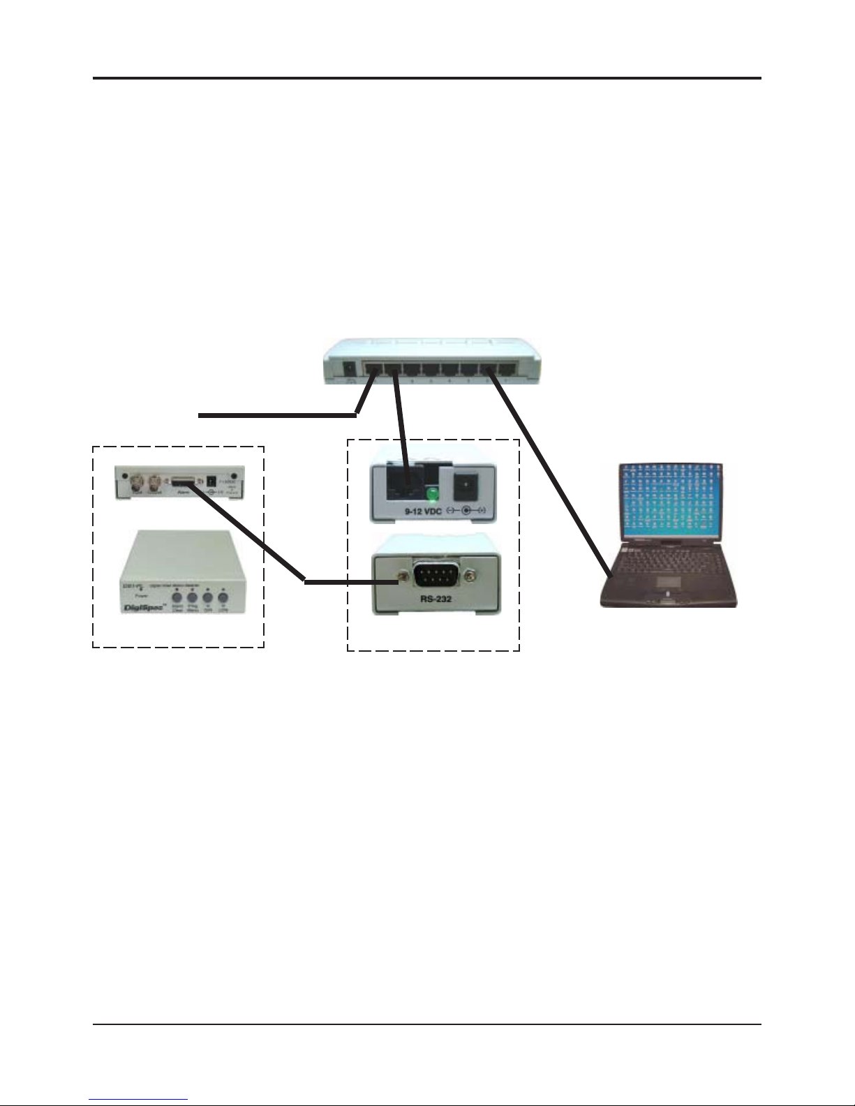
42
DIGITAL VIDEO MOTION DETECTOR
APPENDIX B
Ethernet LAN Adapter
The Ethernet LAN adapter allows for the DS1-PL to be operated on any common LAN network. The adapter connects
to the DS1-PL Serial port and its IP can be set via the on-screen menu of the DS1-PL. When used with conjunction
with our DSVMD Software for Windows you can fully operate and program the DS1-PL remotely . Additional features
like uploading, downloading, and saving configurations are also possible. This software also supports direct serial
connection to the DS1-PL and IP direct programming of the LAN adapter via a PC or laptop.
Additional windows can be opened for simulating the front panel keypad, view alarm status and read the data packet
of the alarm conditions. The data on the LAN is in the UDP format and can conincide with TCP/IP and other LAN
based networks simultaneously .
LAN and DSI-PL Connections
Appendix C - Cable Pinouts
The following cable is for connection from the DS1-PL
to the LAN adapter or from a PC to the DS1-PL for
serial programming.
LAN Adapter or PC DS1-PL
DB9 Female DB15 Male
2 (RXD) ------------------------------------- 13 (TXD)
3 (TXD) ------------------------------------- 14 (RXD)
5 (GND) ------------------------------------- 12 (GND)
The following cable is for the connection from the DS-16 to
the LAN adapter or from a PC to the DS-16 for serial
programming.
Note: The DS-16 is only one way communication and can
not upload or reply any status to the LAN adapter or PC.
LAN Adapter or PC DS-16
DB9 Female DB25 Female
2 (RXD) ------------------------------------- 3 (TXD)
3 (TXD) ------------------------------------- 2 (RXD)
4 (DTR) -------------------------------------- 4 (DTR)
5 (GND) ------------------------------------- 7 (GND)
Table 3: LAN Adapter or PC to DS1-PL
T able 5: LAN Adapter or PC to DS-16
LAN Adapter P C
DB9 Female DB9 Female
2 (RXD) ------------------------------------- 3 (TXD)
3 (TXD) ------------------------------------- 2 (RXD)
5 (GND) -------------------------------------5 (GND)
Table 4: LAN Adapter to PC
Router
Figure 8: LAN and DS1-PL Connections
The cable pin out to the left is for direct programming of the
LAN adapter via a serial port of a PC or Laptop.
DSI-PL
LAN Adapter
Laptop / PC
LAN Network
LAN Network
LAN Network
RS-232 Cable
Page 43
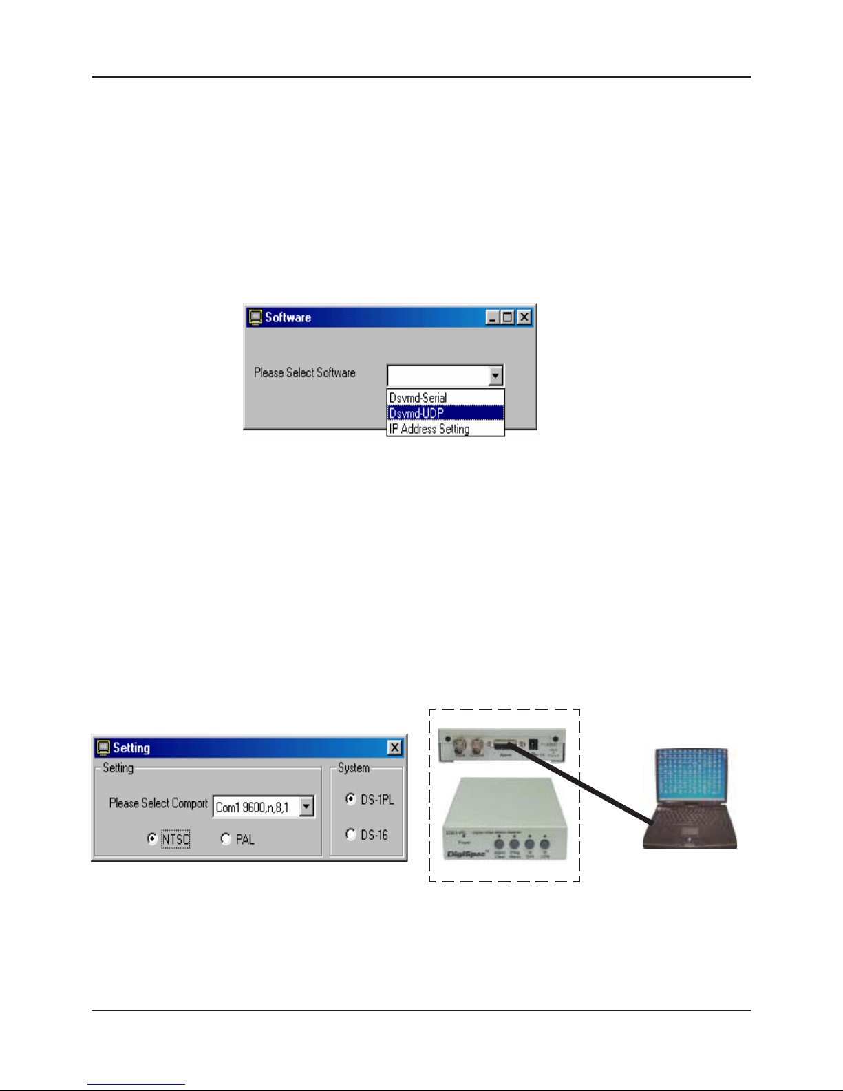
43
DIGITAL VIDEO MOTION DETECTOR
APPENDIX D
DSVMD Software
Installation
Place the included CD-ROM in your drive and should open with menu selections. If it does not open then select
“Explore” of the CD-ROM and double click on the “Setup.exe” file in the software directory . It will look similar to the
following “E:\Software\DSVMD\Setup.exe”. When the installation of the software is finished, then run DSVMD software
from your Program Menu.
Opening Window
Select Software
“DSVMD - Serial” - This selection allows you to directly connect to the DS1-PL via a serial connection from your
PC. The appropriate cable must be connected to a powered up DS1-PL and the connection will be made. If a proper
connection is not made you still can run the program in the off-line mode, save your settings and later connect.
“Dsvmd - UDP” - This selection allows you to connect to the DS1-PL via the Ethernet LAN adapter . The proper IP
address must be programmed into the LAN adapter. This can be done by the on-screen menu of the DS1-PL while the
LAN adapter is connected to the DS1-PL or via the IP Address Setting function below . Then make sure your LAN
adapter is connected to the network and connected to the DS1-PL.
“IP Address Setting” - This selection allows you to directly connect the serial port of the PC to the LAN adapter.
Y ou then can program the IP address directly into the LAN adapter . The IP address is stored in non volatile memory
so will never be lost.
Serial Connection
Setting;
Format NTSC or P AL - Select the proper format for cameras you are using
System DS1-PL or DS-16 - Select the device you are communicating with
Select Comport - Select the baud rate, parity , and bits of the comport connected to the device. The default setting of
the DS1-PL and DS-16 is 4800,n,8,1 so most likely use this first unless you have programmed
another baud rate into the DS1-PL. The DS-16 is always 4800,n,8,1 and can not be changed.
RS-232
Laptop / PC
DSI-PL
Figure 9: Software Select Window
Figure 10: Setting Window
Figure 11: DS1-PL to
Laptop Serial Connection
Page 44
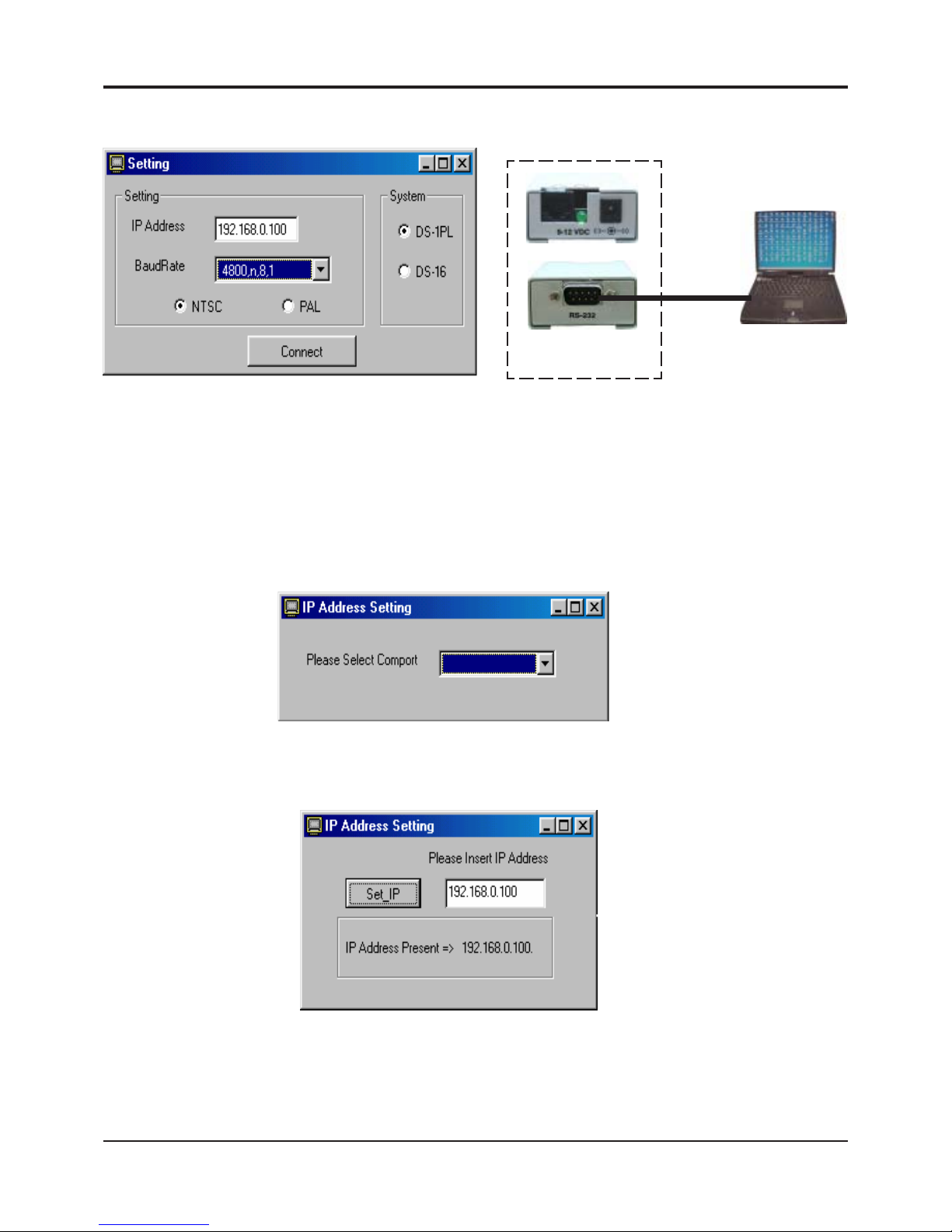
44
DIGITAL VIDEO MOTION DETECTOR
APPENDIX D
Ethernet Connection
Setting;
IP Address - Set the preprogrammed IP address of the LAN adapter
Format NTSC or P AL - Select the proper format for cameras you are using
System DS1-PL or DS-16 - Select the device you are communicating with
BaudRate - Select the baud rate, parity , and bits of the connected device. The default setting of the DS1-PL and DS-
16 is 4800,n,8,1 so most likely use this first unless you have programmed another baud rate into the DS1PL. The DS-16 is always 4800,n,8,1 and can not be changed.
Setup IP Address
Make sure the proper cable is connected from the PC to the LAN adapter. Select the Comport of the PC with baud
rate, parity , and bits. The default baud rate of the LAN adapter is 4800,n,8,1 so select that first unless you have
previously changed.
Type in the IP address you wish the LAN adapter to respond to. The display will show the present IP address programmed into the LAN adapter to show previous setting and to confirm new settings. Check you network IP addresses carefully and make sure you are not duplicating any other IP address on your network or a conflict will occur
and cause problems.
Laptop / PC
LAN Adapter
RS-232
Figure 12: Setting IP/Baud Window
Figure 13: LAN Adpater to Laptop Connection
Figure 14: IP Address Setting Comport
Figure 15: IP Address Setting
Page 45
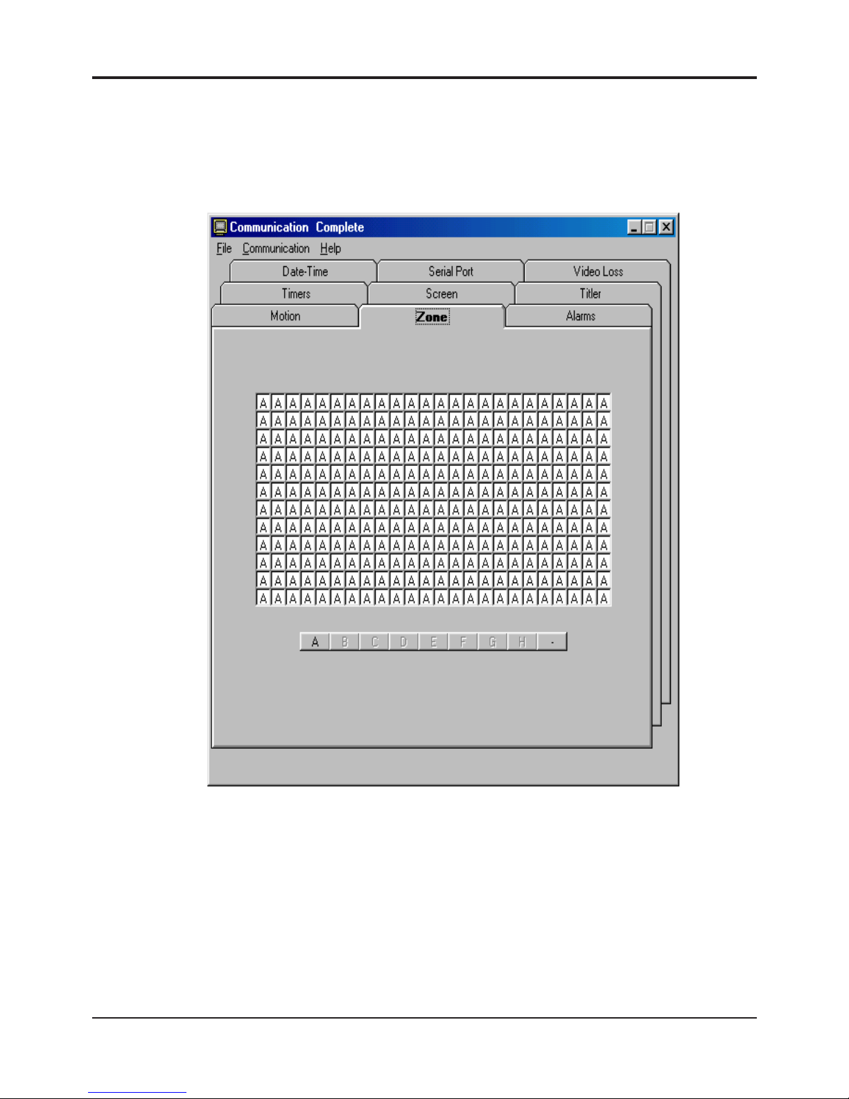
45
APPENDIX D
Communication Complete
Upon successfully selecting one of the previous connection methods the following Main Menu will appear. If cabling or
baud rate or othe communications settings are not correct the error messages will be displayed and you will returned
to the previous menus selections to set correctly .
From this Main Menu you will be able to set all the programming features of the DS1-PL.
“File T ab” - From this tab you can then save them on your PC, or open a previously saved configuration.
“Communications T ab” - From this tab you will be able to open the additional following windows, Keyboard, Alarm,
and Serial or St atus windows, along with Upload settings to the DS1-PL and Download from the DS1-PL to the PC
and select the Day or Night Programming menu.
“Help T ab” - From this tab you can open the online “DS1-PL” Manual for detailed description of each programming
option.
For additional information on the DSVMD Software refer to the DSVMD Software Manual on the included CD-ROM.
DIGITAL VIDEO MOTION DETECTOR
Figure 16: Main Menu
Page 46

46
DIGITAL VIDEO MOTION DETECTOR
SERIAL PROTOCOL REV 10
DS-16 DS1-PL
Serial Configuration 4800 baud Programmable
No parity No Parity
8 data bit 8 data bit
1 or 2 Stop bit s 1 or 2 Stop bit s
CONTROL: T wo types
a) Button Press Control, for simulating front panel button controls.
b) Serial Dump Control, for loading settings from a computer etc.
Serial command for DS1-PL / DS-16 Version 10
<00H>-<7FH> : Unit address 0 –127
<80H>-<8FH> : Unit address blank 0-15,16-31,32-47,48-63,64-79,80-95,96-111,1 12-127
<91H> : Right Button
<92H> : Left Button
<94H> : Menu Button
<98H> : Alarm Button
<A0H> : Unaddress
<A1H> : Day mode
<A2H> : Night mode
<A4H> : Enable Alarm
<A5H> : Disable Alarm
<A8H> : Clear alarm
<B0H> : Done Program(Address Mode)
<B3H> : Menu Mode(Address Mode)
<B4H> : Down Button(Address Mode)
<B5H> : Up Button(Address Mode)
<B6H> : Left Button(Address Mode)
<B7H> : Right Button(Address Mode)
<BDH> : View Log(Address Mode)
Reboot System and Restore Factory Defaults
1. St art (1 byte)
Transmitter: <E0H>
2. Select Address (2 bytes)
Transmitter: <D0H or High nibble (Address)>
<D0H or Low nibble (Address)>
Example: Address of DS1-PL = 04
Transmitter:<D0H>,<D4H>
3. Command (2 Bytes)
Transmitter: <DEH>,<DFH>
4. End Command (1 Byte)
Transmitter:<EFH>
Serial Download
<C0H> : Start download command
<CFH> : End download command
<DXH> : Send data for download command
- Download Date time
- Download Timer(Address Mode)
- Download Registers(Address Mode)
- Download Title(Address Mode)
- Download Zones(Address Mode)
APPENDIX E
Reboot System
1. Start (1 byte)
Transmitter: <E0H>
2. Select Address (2 bytes)
Transmitter: <D0H or High nibble (Address)>
<D0H or Low nibble (Address)>
Example: Address of DS1-PL = 04
Transmitter:<D0H>,<D4H>
3. Command (3 Bytes)
Transmitter: <DEH>,<D0H>
4. End Command (1 Byte)
Transmitter: <EFH>
Page 47

47
DIGITAL VIDEO MOTION DETECTOR
Download Registers
1. Start download (1 byte)
Transmitter: <C0H>
2. Select address (2 bytes)
Transmitter: <D0H OR High nibble(Address)>
<D0H OR Low nibble(Address)>
Ex Address of DS-1PL = 04
Transmitter: <D0H>,<D4H>
3. Length of data (2 bytes)
Transmitter: <D3H>,<DAH>
4. Command for Download Title (4 bytes)
Transmitter: <D0H>,<D2H>,<D0H>,<D0H>
5. Send all registers in this
sequence(1 16 bytes)
5.1 Mode(2 bytes)
OFF <D0H>,<D0H>
MOTION 1 AREA <D0H>,<D1H>
MOTION 2 AREAS <D0H>,<D2H>
MOTION 3 AREAS <D0H>,<D3H>
MOTION 4 AREAS <D0H>,<D4H>
MOTION 5 AREAS <D0H>,<D5H>
MOTION 6 AREAS <D0H>,<D6H>
MOTION 7 AREAS <D0H>,<D7H>
MOTION 8 AREAS <D0H>,<D8H>
DIRECTION A>B <D0H>,<D9H>
DIRECTION A>B G>H <D0H>,<DAH>
MOTION LESS 1 AREA <D0H>,<DBH>
MOTION LESS 8 AREAS <D0H>,<DCH>
MUSEUM <D0H>,<DDH>
PTZ COMP ATIBLE <D0H>,<DEH>
5.2 Buzzer(2 bytes)
OFF <D0H>,<D0H>
ON <D0H>,<D1H>
5.3 Relay output(2 bytes)
OFF <D0H>,<D0H>
ALARM <D0H>,<D1H>
PRETRIG <D0H>,<D2H>
T1 <D0H>,<D3H>
T2 <D0H>,<D4H>
T3 <D0H>,<D5H>
D/N <D0H>,<D6H>
APPENDIX E
5.4 External input(2 bytes)
OFF <D0H>,<D0H>
ALM-AND <D0H>,<D1H>
ALM-OR <D0H>,<D2H>
EN A <D0H>,<D3H>
DISA <D0H>,<D4H>
D/N <D0H>,<D5H>
CAPREF <D0H>,<D6H>
5.5 Watchdog Timer(2 bytes)
OFF <D0H>,<D0H>
ON <D0H>,<D1H>
5.6 Entrance delay(2 bytes)
00 <D0H>,<D0H>
99 <D6H>,<D3H>
5.7 Exit delay(2 bytes)
00 <D0H>,<D0H>
99 <D6H>,<D3H>
5.8 Alarm Process(2 bytes)
Time <D0H>,<D0H>
Retrigger <D0H>,<D0H>
5.9 Alarm Output Time(2 bytes)
Man <D0H>,<D0H>
01 <D0H>,<D1H>
99 <D6H>,<D3H>
5.10 Alarm reset time(2 bytes)
00 <D0H>,<D0H>
99 <D6H>,<D3H>
5.11 Display layout(2 bytes)
OFF <D0H>,<D0H>
STACKED <D0H>,<D1H>
SERIES <D0H>,<D2H>
5.12 Horizontal position(2 bytes)
1 <D0H>,<D1H>
12 <D0H>,<DCH>
5.13 Vertical position(2 bytes)
1 <D0H>,<D1H>
NTSC 22 <D1H>,<D6H>
PAL 27 <D1H>,<DBH>
Page 48

48
5.14 Status(2 bytes)
OFF <D0H>,<D0H>
AREA A DEL TA <D0H>,<D1H>
AREA B DELTA <D0H>,<D2H>
AREA C DELTA <D0H>,<D3H>
AREA D DELTA <D0H>,<D4H>
AREA E DELTA <D0H>,<D5H>
AREA F DEL T A <D0H>,<D6H>
AREA G DELTA <D0H>,<D7H>
AREA H DELTA <D0H>,<D8H>
ALL DEL T A <D0H>,<D9H>
ALM FLAGS <D0H>,<DAH>
5.15 Calendar(2 bytes)
OFF <D0H>,<D0H>
MMM-DD-YY <D0H>,<D1H>
YY-MMM-DD <D0H>,<D2H>
DD-MMM-YY <D0H>,<D3H>
5.16 Time display(2 bytes)
OFF <D0H>,<D0H>
12 HOUR <D0H>,<D1H>
24 HOUR <D0H>,<D2H>
5.17 Trace Effect(2 bytes)
OFF <D0H>,<D0H>
MOTION <D0H>,<D1H>
MEMORY <D0H>,<D2H>
MEMORY/F <D0H>,<D3H>
MEMORY/S <D0H>,<D4H>
MEMORY/A <D0H>,<D5H>
MEMORY/AS <D0H>,<D6H>
5.18 Video blackout(2 bytes)
OFF <D0H>,<D0H>
ON <D0H>,<D1H>
AUTO <D0H>,<D2H>
AUTO RST
5.19 Titler display(2 bytes)
OFF <D0H>,<D0H>
ON <D0H>,<D1H>
5.20 Serial port(2 bytes)
1200,n,8,1 <D0H>,<D0H>
2400,n,8,1 <D0H>,<D1H>
4800,n,8,1 <D0H>,<D2H>
9600,n,8,1 <D0H>,<D3H>
19200,n,8,1 <D0H>,<D4H>
28800,n,8,1 <D0H>,<D5H>
DIGITAL VIDEO MOTION DETECTOR
APPENDIX E
5.21 Address(2 bytes)
00 <D0H>,<D0H>
127 <D7H>,<DFH>
5.22 Output rate(2 bytes)
OFF <D0H>,<D0H>
PER ALARM <D0H>,<D1H>
CONTINUOUS <D0H>,<D2H>
5.23 Output data(2 bytes)
MOVE FLAGS <D0H>,<D0H>
TRIG FLAGS <D0H>,<D1H>
ALARM FLAGS <D0H>,<D2H>
STAT FLAGS <D0H>,<D3H>
ALL FLAGS <D0H>,<D4H>
AREA1 DEL TA <D0H>,<D5H>
AREA2 DEL TA <D0H>,<D6H>
AREA3 DEL TA <D0H>,<D7H>
AREA4 DEL TA <D0H>,<D8H>
AREA5 DEL TA <D0H>,<D9H>
AREA6 DEL TA <D0H>,<DAH>
AREA7 DEL TA <D0H>,<DBH>
AREA8 DEL TA <D0H>,<DCH>
TOT AL DEL T A <D0H>,<DDH>
EVENT LOG <D0H>,<DEH>
5.24 Video loss alarm(2 bytes)
OFF <D0H>,<D0H>
ON <D0H>,<D1H>
5.25 Video loss buzzer(2 bytes)
OFF <D0H>,<D0H>
ON <D0H>,<D1H>
5.26 Video loss output(2 bytes)
RED SCREEN <D0H>,<D0H>
VIDEO <D0H>,<D1H>
5.27 Sensitivity(16 bytes)
00 <D0H>,<D0H>
99 <D6H>,<D3H>
Sensitivity Zone A 2 bytes
Sensitivity Zone B 2 bytes
Sensitivity Zone C 2 bytes
Sensitivity Zone D 2 bytes
Sensitivity Zone E 2 bytes
Sensitivity Zone F 2 bytes
Sensitivity Zone G 2 bytes
Sensitivity Zone H 2 bytes
Page 49

49
DIGITAL VIDEO MOTION DETECTOR
APPENDIX E
5.28 Trigger level(32 bytes)
0 <D0H>,<D0H>,<D0H>,<D0H>
65,535 <DFH>,<DFH>,<DFH>,<DFH>
Trigger Level Zone A 4 bytes
Trigger Level Zone B 4 bytes
Trigger Level Zone C 4 bytes
Trigger Level Zone D 4 bytes
Trigger Level Zone E 4 bytes
Trigger Level Zone F 4 bytes
Trigger Level Zone G 4 bytes
Trigger Level Zone H 4 bytes
5.29 Tracking T ime Setting (16 bytes)
0.0sec <D0H>,<D0H>
0.1 sec <D0H>,<D1H>
0.9 sec <D0H>,<D9H>
1.0 sec <D0H>,<DAH>
7.9 sec <D4H>,<DFH>
8.0 sec <D5H>,<D0H>
10 sec <D6H>,<D4H>
11 sec <D6H>,<D5H>
59 sec <D9H>,<D5H>
1.00 minute <D9H>,<D6H>
1.05 minute <D9H>,<D7H>
1.10 minute <D9H>,<D8H>
1.55 minute <DAH>,<D1H>
2.00 minute <DAH>,<D2H>
3.00 minute <DAH>,<DEH>
4.00 minute <DBH>,<DAH>
5.00 minute <DCH>,<D6H>
Tracking Zone A 2 bytes
Tracking Zone B 2 bytes
Tracking Zone C 2 bytes
Tracking Zone D 2 bytes
Tracking Zone E 2 bytes
Tracking Zone F 2 bytes
Tracking Zone G 2 bytes
Tracking Zone H 2 bytes
6. End command(1 byte)
Transmitter: <CFh>
Download Zones
1. Start download (1 byte)
Transmitter: <C0H>
2. Select address (2 bytes)
Transmitter: <D0H OR High nibble(Address)>
<D0H OR Low nibble (Address)>
Ex Address of Ds-1pl = 03
Transmitter: <D0H>,<D3H>
3. Length of data (2 bytes)
Transmitter: <D4H>,<D8H>
4. Command for download Zones(4 bytes)
*Row 1 Column – Row 6 Column 24
Transmitter: <D0H>,<D4H>,<D0H>,<D0H>
*Row 7 Column – Row 12 Column 24
Transmitter: <D0H>,<D5H>,<D0H>,<D0H>
5. Send all registers in this
sequence(144 bytes)
Row 1 Column 1-24 1 - 24
Row 2 Column 1-24 25 - 48
Row 3 Column 1-24 49 - 72
Row 4 Column 1-24 73 - 96
Row 5 Column 1-24 97 - 120
Row 6 Column 1-24 121 - 144
Row 7 Column 1-24 1 - 24
Row 8 Column 1-24 25 - 48
Row 9 Column 1-24 49 - 72
Row 10 Column 1-24 73 - 96
Row 11 Column 1-24 97 - 120
Row 12 Column 1-24 121 - 144
A <D0H>
B <D1H>
C <D2H>
D <D3H>
E <D4H>
F <D5H>
G <D6H>
H <D7H>
OFF <D8H>
6. End command(1 byte)
Transmitter: <CFh>
Page 50

50
DIGITAL VIDEO MOTION DETECTOR
APPENDIX E
Download Date Time
1. Start download (1 byte)
Transmitter: <C0H>
2. Select all address (2 bytes)
Transmitter: <D8H>,<D0H>
3. Length of data (2 bytes)
Transmitter: <D0H>,<D9H>
4. Command for download date time(4 bytes)
Transmitter: <D0H>,<D0H>,<D0H>,<D0H>
5. Send all registers in this sequence(18 bytes)
5.1 Month
JAN <D0H>,<D1H>
FEB <D0H>,<D2H>
MAR <D0H>,<D3H>
APR <D0H>,<D4H>
MAY <D0H>,<D5H>
JUN <D0H>,<D6H>
JUL <D0H>,<D7H>
AUG <D0H>,<D8H>
SEP <D0H>,<D9H>
OCT <D1H>,<D0H>
NOV <D1H>,<D1H>
DEC <D1H>,<D2H>
5.2 Date
00 <D0H>,<D0H>
31 <D3H>,<D1H>
5.3 Year
00 <D0H>,<D0H>
99 <D9H>,<D9H>
5.4 Hours
00 <D0H>,<D0H>
23 <D2H>,<D3H>
5.5 Minutes
00 <D0H>,<D0H>
59 <D5H>,<D9H>
5.6 Second
00 <D0H>,<D0H>
59 <D5H>,<D9H>
5.7 Day of week
SUN <D0H>,<D1H>
MON <D0H>,<D2H>
TUE <D0H>,<D3H>
WED <D0H>,<D4H>
T HU <D0H>,<D5H>
FR I <D0H>,<D6H>
SAT <D0H>,<D7H>
5.8 Alarm Counter
00 <D0H>,<D0H>
99 <D6H>,<D3H>
5.9 Daylight Saving Time
OFF <D0H>,<D0H>
USA <D0H>,<D1H>
CANADA <D0H>,<D2H>
6. End command(1 byte)
Transmitter: <CFh>
Download Timer
1. Start download (1 byte)
Transmitter: <C0H>
2. Select address (2 bytes)
Transmitter: <D0H OR High nibble(Address)>
<D0H OR Low nibble(Address)>
Example: Address of DS-1PL = 02
Transmitter: <D0H>,<D2H>
3. Length of data (2 bytes)
Transmitter: <D1H>,<D4H>
4. Command for download timer(4 bytes)
Transmitter: <D0H>,<D1H>,<D0H>,<D0H>
5. Send all registers in this sequence(40 bytes)
Page 51

51
DIGITAL VIDEO MOTION DETECTOR
APPENDIX E
5.1 Timer1
OFF <D0H>,<D0H>
SUN <D0H>,<D1H>
MON <D0H>,<D2H>
TUE <D0H>,<D3H>
WED <D0H>,<D4H>
T HU <D0H>,<D5H>
FR I <D0H>,<D6H>
SAT <D0H>,<D7H>
M-F <D0H>,<D8H>
M-S <D0H>,<D9H>
S-S <D0H>,<DAH>
ALL <D0H>,<DBH>
5.2 Timer1 hour start
00 <D0H>,<D0H>
23 <D2H>,<D3H>
5.3 Timer1 minute start
00 <D0H>,<D0H>
59 <D5H>,<D9H>
5.4 Timer1 hour stop
00 <D0H>,<D0H>
23 <D2H>,<D3H>
5.5 Timer1 minute stop
00 <D0H>,<D0H>
59 <D5H>,<D9H>
5.6 Timer2
OFF <D0H>,<D0H>
SUN <D0H>,<D1H>
MON <D0H>,<D2H>
TUE <D0H>,<D3H>
WED <D0H>,<D4H>
T HU <D0H>,<D5H>
FR I <D0H>,<D6H>
SAT <D0H>,<D7H>
M-F <D0H>,<D8H>
M-S <D0H>,<D9H>
S-S <D0H>,<DAH>
ALL <D0H>,<DBH>
5.7 Timer2 hour start
00 <D0H>,<D0H>
23 <D2H>,<D3H>
5.8 Timer2 minute start
00 <D0H>,<D0H>
59 <D5H>,<D9H>
5.9 Timer2 hour stop
00 <D0H>,<D0H>
23 <D2H>,<D3H>
5.10 Timer1 minute stop
00 <D0H>,<D0H>
59 <D5H>,<D9H>
5.11 T imer 3
OFF <D0H>,<D0H>
SUN <D0H>,<D1H>
MON <D0H>,<D2H>
TUE <D0H>,<D3H>
WED <D0H>,<D4H>
T HU <D0H>,<D5H>
FR I <D0H>,<D6H>
SAT <D0H>,<D7H>
M-F <D0H>,<D8H>
M-S <D0H>,<D9H>
S-S <D0H>,<DAH>
ALL <D0H>,<DBH>
5.12 Timer3 hour start
00 <D0H>,<D0H>
24 <D2H>,<D3H>
5.13 Timer3 minute start
00 <D0H>,<D0H>
59 <D5H>,<D9H>
5.14 Timer3 hour stop
00 <D0H>,<D0H>
23 <D2H>,<D3H>
5.15 Timer3 minute stop
00 <D0H>,<D0H>
59 <D5H>,<D9H>
5.16 Day/Night Timers
OFF <D0H>,<D0H>
ON <D0H>,<D1H>
5.17 Day hour start
00 <D0H>,<D0H>
23 <D2H>,<D3H>
5.18 Day minute start
00 <D0H>,<D0H>
59 <D5H>,<D9H>
Page 52
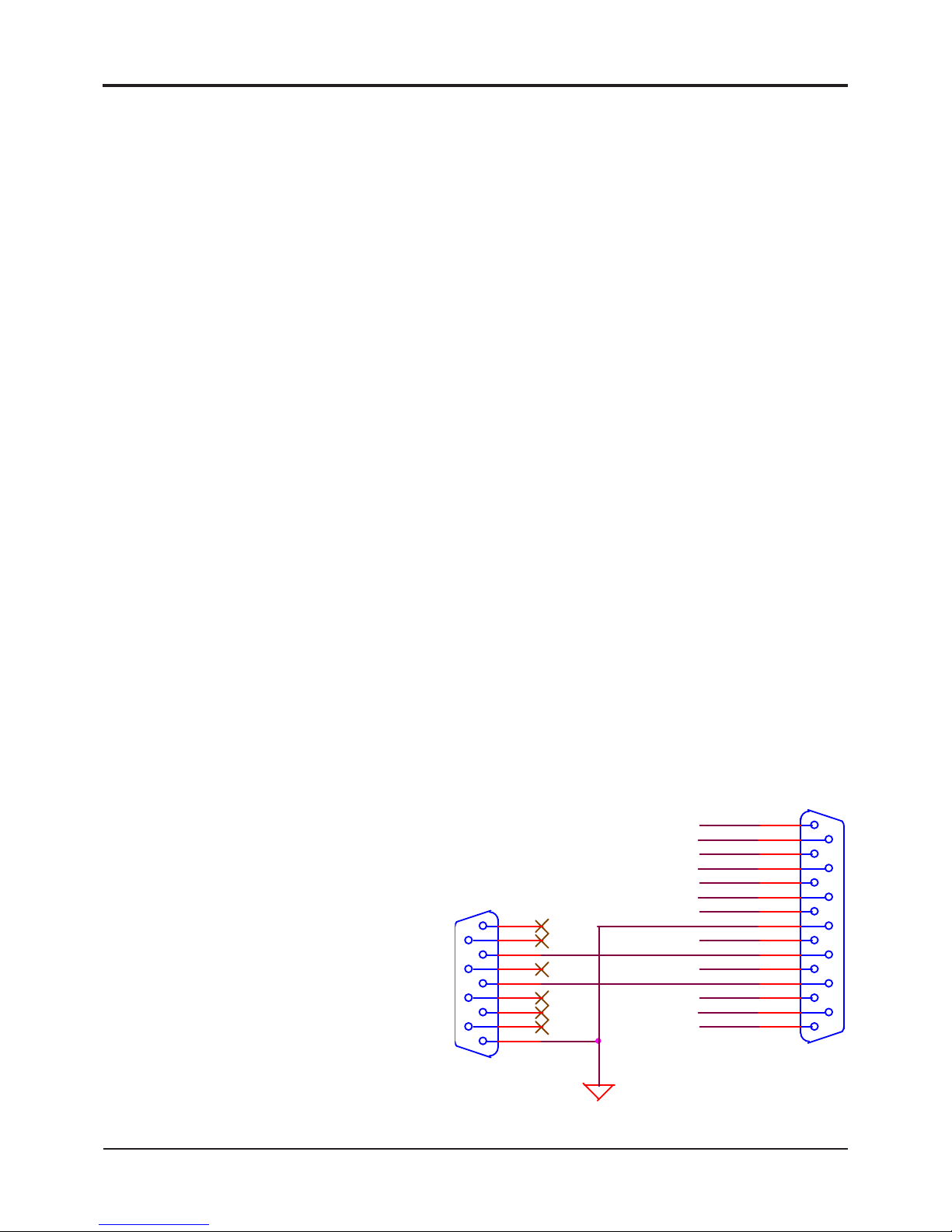
52
DIGITAL VIDEO MOTION DETECTOR
APPENDIX E
5.19 Night hour start
00 <D0H>,<D0H>
23 <D2H>,<D3H>
5.20 Night minute start
00 <D0H>,<D0H>
59 <D5H>,<D9H>
6. End command(1 byte)
Transmitter: <CFh>
Download Title
1. Start download (1 byte)
Transmitter: <C0H>
2. Select address (2 bytes)
Transmitter: <D0H OR Highnibble(Address)>
<D0H OR Low nibble(Address)>
Example: Address of Ds-1pl = 01
Transmitter: <D0H>,<D1H>
3. Length of data (2 bytes)
Transmitter: <D1H>,<D1H>
4. Command for DownloadTtitle (4 bytes)
Transmitter: <D0H>,<D3H>,<D0H>,<D0H>
5. Title 32 Bytes for 16 characters
‘0’ = <D0H>,<D0H>
‘1’ = <D0H>,<D1H>
‘2’ = <D0H>,<D2H>
‘3’ = <D0H>,<D3H>
‘4’ = <D0H>,<D4H>
‘5’ = <D0H>,<D5H>
‘6’ = <D0H>,<D6H>
‘7’ = <D0H>,<D7H>
‘8’ = <D0H>,<D8H>
‘9’ = <D0H>,<D9H>
‘:’ = <D0H>,<DAH>
‘<’ = <D0H>,<DBH>
‘>’ = <D0H>,<DCH>
‘-‘ = <D0H>,<DDH>
‘.’ = <D0H>,<DEH>
‘,’ = <D0H>,<DFH>
Sp ace = <D1H>,<D0H>
‘A’ = <D1H>,<D1H>
‘B’ = <D1H>,<D2H>
‘C’ = <D1H>,<D3H>
‘D’ = <D1H>,<D4H>
‘E’ = <D1H>,<D5H>
‘F’ = <D1H>,<D6H>
‘G’ = <D1H>,<D7H>
‘H’ = <D1H>,<D8H>
‘I’ = <D1H>,<D9H>
‘J’ = <D1H>,<DAH>
‘K’ = <D1H>,<DBH>
‘L’ = <D1H>,<DCH>
‘M’ = <D1H>,<DDH>
‘N’ = <D1H>,<DEH>
‘O’ = <D0H>,<D0H>
‘P’ = <D2H>,<D0H>
‘Q’ = <D2H>,<D1H>
‘R’ = <D2H>,<D2H>
‘S’ = <D2H>,<D3H>
‘T’ = <D2H>,<D4H>
‘U’ = <D2H>,<D5H>
‘V’ = <D2H>,<D6H>
‘W’ = <D2H>,<D7H>
‘X’ = <D2H>,<D8H>
‘Y’ = <D2H>,<D9H>
‘Z’ = <D2H>,<DAH>
6. Relay State (2 bytes)
NO <D0H>, <D0H>
N C <D0H>, <D1H>
7. End command(1 byte)
Transmitter: <CFh>
SER_OUT
RXD
SER_INPTXD
Alm_B
Alm_C
Alm_D
Alm_E
Alm_F
Alm_G
Alm_H
Alm_A
N/C
N/O
Common
X_INP
DB15
DS1-PL
8
15
7
14
6
13
5
12
4
11
3
10
2
9
1
DB9
Comport
5
9
4
8
3
7
2
6
1
APPENDIX F
PC to DS1-PL Connection Pin-Out
Female Male
Figure 17 : PC to DS1-PL Connection Pin-Out
Page 53
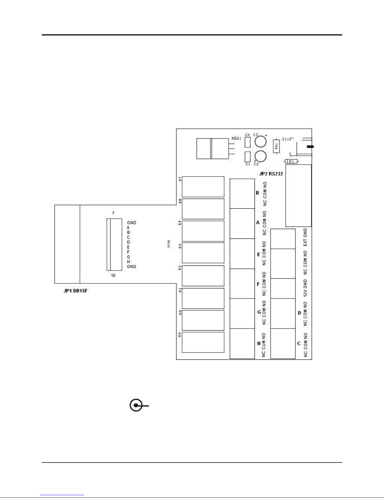
53
(-) (+)
DIGIT AL VIDEO MOTION DETECTOR
APPENDIX G
Figure 18 : DS1-PL Relay Adapter PCB Silkscreen &Pinouts
DS1-PL Relay Adapter
Intoduction
DS1PL Relay Adapter is an alarm relay interface for the DS1PL. It connects to the DB15 on
the back panel and allows for the breakout of all connections including all alarms in & out and
also includes RS-232 connection to a DB9 Female to connect with a standard RS232 cable
between the PC and the DS1-PL. A 10 Pin header connector for the TTL level alarm outputs
is also provided for direct digital interface.
PCB Silkscreen & Pinouts
12VDC
Input
PC
DB9
RS-232
Alarm
Relay
Outputs
Alarm
TTL Outputs
DB15 to
DS1-PL
Power : 7.5 - 12VDC@ 6mA Normal mode; 280mA Maximum Alarm mode
2.1mm x 5.5mm DC Power Connector Center Positive
RS-232 PC Cable Pin Out
DB9 Male DS1-PL -----------------------------------DB9 Female (PC)
2----------------------------------------------------------3
3----------------------------------------------------------2
5----------------------------------------------------------5
Relay: 1A @ 30 VDC
0.3A @ 125 VAC
0.3A @ 110 VDC
Page 54
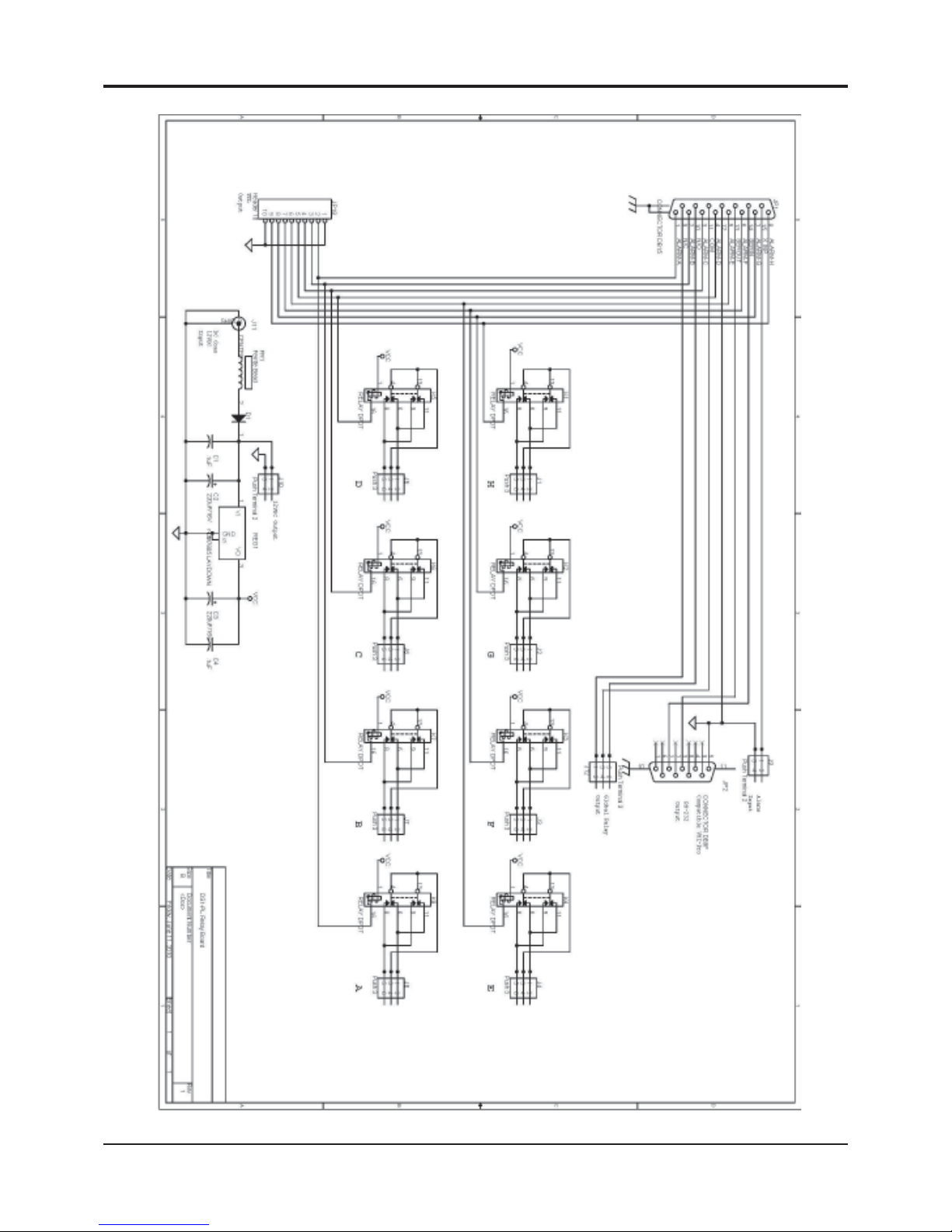
54
DS1-PL Alarm Relay Board Schematic
Figure 19 : DS1-PL Alarm Relay Board Schematic
DIGIT AL VIDEO MOTION DETECTOR
APPENDIX G
Page 55

55
DIGITAL VIDEO MOTION DETECTOR
WARRANTRY
Limited Warranty
(T erms and Conditions)
LIMITED WARRANTY
For 2 Years from the date of shipment, Seller warrants to Buyer that the Product is free from defects in material or workman-
ship UNDER NORMAL USE AND SERVICE. Equipment manufactured or supplied by others (manufacturers other than
Seller) but furnished by Seller carries the same warranty to Buyer as Seller receives from the other manufacturer, NOTWITHST ANDING ANY PROVISION TO THE CONTRARY, if Buyer has specified a particular manufacturer’s product which is not
the brand standardly supplied by Seller, Buyer shall look only to the other manufacturer’s warranty and Seller shall not
warrant such item. In such event, Buyer shall obtain only the warranty which comes with such other manufacturer’s product.
EXCLUSIONS. Seller’s warranty does not cover the following:
(1) in transit damage claims, improper handling by carrier or post office (NOTE: only the consignee of the
shipment can file a claim with the common Carrier);
(2) damages caused by incorrect use, modification, carelessness, unauthorized alterations, improper
storage or unauthorized service, installation or repairs;
(3) damages caused by fire, flood, lightning, collision, acts of God or other events beyond the control of
Seller;
(4) products or parts thereof that have had serial numbers removed, altered or defaced;
(5) products received for repair without a RMA number and a sales or delivery receipt showing the date of
original purchase;
(6) hostile operating conditions;
(7) use of components that do not meet Seller’s specifications;
(8) damage or failure caused by or resulting from the operation of the product with incorrect voltage;
(9) external parts such as cabinets or keypads;
(10) periodic maintenance and adjustments resulting from normal use.
(11) installation or repair of the equipment without proper training from the Seller
WARRANTIES EXCLUDED
SELLER EXPRESSLY DISCLAIMS AND EXCLUDES ANY EXPRESS OR IMPLIED WARRANTY OR MERCHANTABILITY OR FITNESS FOR A ’ P ARTICULAR PURPOSE WHICH EXCEEDS OR IS INCONSISTENT WITH THE W ARRANTY HEREIN EXPRESSL Y SET FORTH.
NON-WARRANTY CLAIMS
In the event Buyer makes a warranty claim and Seller’s warranty does not apply, Buyer shall reimburse Seller for all
reasonable expenses incurred by Seller in diagnosing the Installation/repair problem. Seller shall not be responsible for any
damages to the Product or other property due to installation or service by a party not authorized by Seller .
BUYER’S EXCLUSIVE REMEDIES
If the Product supplied shall fail to conform to the contract or any applicable warranty , Buyer shall immediately notify Seller
of such condition and afford Seller a reasonable opportunity to inspect said Product. Seller shall, at its option, either repair or
replace such nonconforming Product. Seller shall not be responsible for labor charges for removal or installation of such
equipment or material or charges for transportation, handling and shipping except as provided in Seller’s written service
policy . No Product shall be returned without Seller’s prior written consent.
SELLER SHALL NOT BE LIABLE FOR ANY SPECIAL, DIRECT INCIDENTAL OR CONSEQUENTIAL DAMAGES OF A
COMMERCIAL NA TURE ARISING OUT THE USE OF OR INABILITY T O USE SELLER’S PRODUCT BY REASON OF
THE FACT THA T SUCH PRODUCT DOES NOT CONFORM TO THE CONTRACT OR T O ANY EXPRESS OR IMPLIED
WARRANTY. SELLER’S MAXIMUM LIABILITY SHALL BE LIMITED TO THE COST OF REP AIR AND/OR REPLACEMENT OF THE PRODUCT CLAIMED TO BE DEFECTIVE OR NONCONFORMING , SUBJECT TO SELLER’S RIGHT OF
REMOV AL AND RETURN OF PRODUCT.
Page 56

56
DIGITAL VIDEO MOTION DETECTOR
W ARRANTRY
All of the foregoing constitute Buyer’s sole and exclusive remedy and Seller’s sole and exclusive liability for supplying
nonconforming or defective Product.
RETURNS
Returns of standard stocking items with no restocking fee can only be made within thirty (30) days of invoice to Buyer. All
such returns must be in unopened original packaging. Any other returns must have prior written consent of Seller and
restocking fee of not less than fifteen percent (15%) will apply .
To locate the service or dealer nearest you, or for service assistance or resolution of a service problem, or for product
information or operation, contact DigiSpec at.
Tel: 281-540-6665
Fax: 281-540-6972
Email: [email protected]
NOTES:
_________________________________________________________________________________________________
_________________________________________________________________________________________________
_________________________________________________________________________________________________
_________________________________________________________________________________________________
_________________________________________________________________________________________________
_________________________________________________________________________________________________
_________________________________________________________________________________________________
__________________________________________________________________________________________________
_________________________________________________________________________________________________
_________________________________________________________________________________________________
_________________________________________________________________________________________________
_________________________________________________________________________________________________
Page 57

57
_________________________________________________________________________________________________
_________________________________________________________________________________________________
_________________________________________________________________________________________________
_________________________________________________________________________________________________
_________________________________________________________________________________________________
_________________________________________________________________________________________________
_________________________________________________________________________________________________
__________________________________________________________________________________________________
_________________________________________________________________________________________________
_________________________________________________________________________________________________
_________________________________________________________________________________________________
_________________________________________________________________________________________________
NOTES
_________________________________________________________________________________________________
_________________________________________________________________________________________________
_________________________________________________________________________________________________
_________________________________________________________________________________________________
_________________________________________________________________________________________________
_________________________________________________________________________________________________
_________________________________________________________________________________________________
DIGITAL VIDEO MOTION DETECTOR
Page 58

58
_________________________________________________________________________________________________
_________________________________________________________________________________________________
_________________________________________________________________________________________________
_________________________________________________________________________________________________
_________________________________________________________________________________________________
_________________________________________________________________________________________________
_________________________________________________________________________________________________
__________________________________________________________________________________________________
_________________________________________________________________________________________________
_________________________________________________________________________________________________
_________________________________________________________________________________________________
_________________________________________________________________________________________________
NOTES
_________________________________________________________________________________________________
_________________________________________________________________________________________________
_________________________________________________________________________________________________
_________________________________________________________________________________________________
_________________________________________________________________________________________________
_________________________________________________________________________________________________
_________________________________________________________________________________________________
DIGITAL VIDEO MOTION DETECTOR
Page 59

59
Page 60

60
DigiSpec Inc.
1906 Treble Dr.
Humble, Texas 77338
Tel: 281-540-6665 Fax: 281-540-6972
Email:
Web Site: www.digispecvideomotion.com
TM
 Loading...