

Page 1
DG-BG1100N
802.11N 150MBPS SINGLE PORT WIRELE SS ADSL2/2+
ROUTER
User Manual
V1.0
2013-12-12
As our products undergo continuous development the specifications are subject to change without prior notice
Page 2

DG-BG1100N Use r Manual
2
Index
1
Product Information .............................................................................................. 4
1.1
Safety Precautions .................................................................................. 4
1.2
Package Contents ................................................................................... 5
1.3
Features ................................................................................................... 5
1.4
System Requirements ............................................................................. 6
1.5
LEDs and Interfaces ................................................................................ 7
2
Hardware Installation .......................................................................................... 10
2.1
Softw are Inst all ation .............................................................................. 11
2.2
PC Network Configuration ..................................................................... 21
3
Accessing the Internet ........................................................................................ 23
3.1
Accessing the Internet by Wireless Connection ................................... 23
3.2
Accessing the Internet in Bridge Mode ................................................. 25
4
Web Configuration .............................................................................................. 26
4.1
Access the Router ................................................................................. 26
4.1.1
Status ..................................................................................... 27
4.1.2
Device Info ............................................................................ 27
4.1.3
Syst em L og ........................................................................... 28
4.1.4
Statistics ................................................................................ 28
4.2
Quick Start ............................................................................................. 30
4.3
Interface Setup ...................................................................................... 40
4.3.1
Internet .................................................................................. 40
4.3.2
LAN ........................................................................................ 46
4.3.3
Wireless ................................................................................. 50
4.4
Advanced S etup .................................................................................... 53
4.4.1
Firewall .................................................................................. 53
4.4.2
Routing .................................................................................. 53
4.4.3
NAT ........................................................................................ 55
4.4.4
VLAN ..................................................................................... 59
4.4.5
ADSL ..................................................................................... 62
4.5
Access Management ............................................................................. 63
4.5.1
ACL ........................................................................................ 63
4.5.2
Filter ....................................................................................... 64
Page 3

DG-BG1100N Use r Manual
3
4.5.3
SNMP .................................................................................... 67
4.5.4
UPnP ..................................................................................... 68
4.5.5
DDNS .................................................................................... 69
4.5.6
CWMP ................................................................................... 70
4.6
Maintenance .......................................................................................... 71
4.6.1
Administration ....................................................................... 71
4.6.2
Time Zone ............................................................................. 72
4.6.3
Firmware ............................................................................... 73
4.6.4
SysRestart ............................................................................. 74
4.6.5
Diagnostics ............................................................................ 75
4.7
Troubleshooting ..................................................................................... 76
Page 4

DG-BG1100N Use r Manual
4
1 Product Information
The DG-BG1100N device is an ADSL access device that supports multiple line modes. It
provides one 10/100Base-T Ethernet interface at the user end. The device provides
high-speed ADSL broadband c onnec tion and supports wir el ess networ k access to the Internet
or Intranet for high-end users such as net cafes and office users . The devic e provides high
performance access to the Internet, downlink up to 24 Mbps and uplink up to 1 Mbps.
1.1 Safety Precautions
Take the following instructions to prevent th e de vice from ri s ks and dam age c aused b y fi re or
electric power.
•
Use the type of power marked by the volume label.
•
Use the power adapter in the device package.
•
Pay attention to the power load of the outlet or prolonged lines. An overburden power
outlet or damaged lines and plugs may cause electric shock or fire accident. Check
the power cords regularly. If you find any damage, replace it at once.
•
Proper space left for heat dissipation is necessary to avoid damage caused by
overheating the device. The long and thin holes on the device are designed for heat
dissipation to ensure that the device works normally. Do not cover these heat
dissipation holes.
•
Do not put this device close to a place where a heat source exists or high temperature
occurs. Avoid the device from direct sunshine.
•
Do not put this device close to a place where it is over damp or watery. Do not spill any
fluid on this device.
•
Do not connect this device to PCs or electronic products, unless our engineer or your
broadband provider instructs you to do this, because any wrong connection may
cause power or fire risk.
•
Do not place this device on an unstable surface or support.
Page 5

DG-BG1100N Use r Manual
5
1.2 Package Contents
Before you star t using this router, please chec k if there’s anything miss ing in the package, and
contact your dealer of purchase to claim for missing items:
•
1 x ADSL Wireless router
•
2 x Telephone cables (RJ11)
•
1 x Ethernet cable (RJ45)
•
1 x External ADSL splitter
•
1 x Power adapter (DC12V 0.5A, EU)
•
Installation Guide CD ( includes user manual, QIG & Utility)
•
Quick Installation Guide
1.3 Features
The device supports the following features:
•
Various line modes
•
Wireless network access
•
External PPPoE dial-up access
•
Internal PPPoE/PPPoA dial-up access
• 1483Bridged/1483Routed with dynamic IP or static IP
•
Multiple PVCs (the number of PVCs support is eight)
•
DHCP server/relay
•
Static route
•
Network Address Translation(NA T)
•
DMZ
•
Virtual Server
•
Universal plug and play (UPnP)
•
Dynamic Domain Name Server(DDNS)
•
One-level password and username
•
Network Time Protocol(NTP)
•
Firmware upgrading through Web, TFTP, or FTP
•
Resetting to the factory defaults through Reset button or Web
•
Diagnostic test
• Web interface
Page 6

DG-BG1100N Use r Manual
6
•
Telnet CLI
•
IP/MAC/URL Filter
•
Application layer service
•
QOS
•
Port binding
1.4 System Requirements
Recommended system requirements are as follows:
•
A 10/100 base-T Ethernet card is installed on your PC.
•
A hub or Switch. (To connect several PCs through one of the Ethernet interfaces on the
device.)
•
Operating system: Windows 98 SE, Windows 2000, Windows ME, Windows XP,
Windows Vista, Windows 7.
•
Internet Explorer V5.0 or higher, Netscape V4.0 or higher, or Firefox 1.5 or higher.
Page 7
DG-BG1100N Use r Manual
7
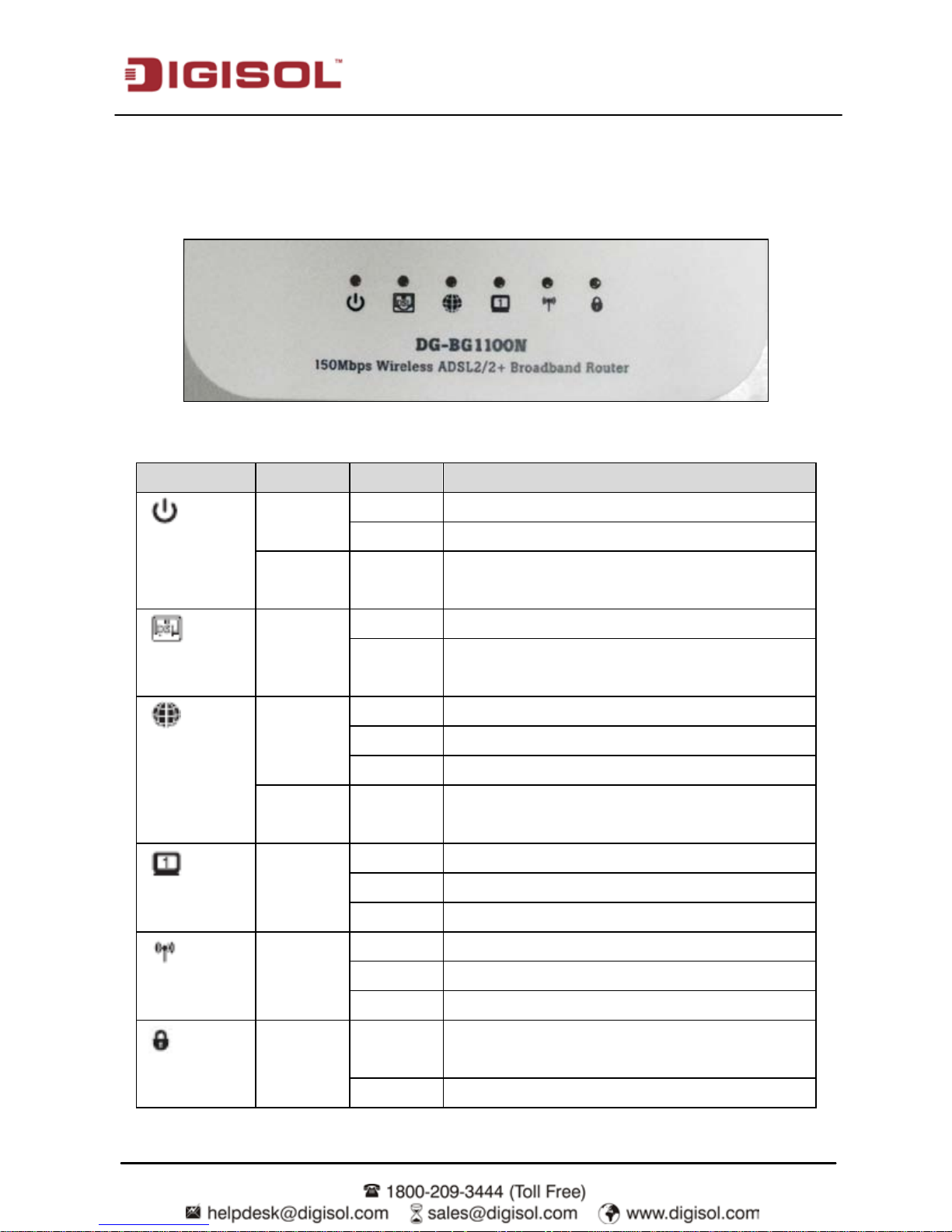
1.5 LEDs and Interfaces
Top Panel
The following table describes the LEDs of the device:
LEDs Color Status Description
Power
Green On Power is ON.
Off Power is OFF.
Red On The device is initializing or initialization has
failed.
DSL
Green On DSL physical link is up.
Blinking ADSL handshaking pr ocess is on or ADSL line
unplugged.
Internet
Green On Internet connection is established.
Blinking Data is beihng transmitted or received.
Off Set as bridge mode.
Red On PPPoE/ PPPo A user nam e-passw ord not set or
is wrong.
LAN
Green On PC is connected to the LAN port.
Blinking Data is being transmitted or received.
Off PC is unplugged / Not connected.
WLAN
Green On Wireless is enabled.
Blinking Data is being transmitted or received.
Off Wireless is not enabled.
WPS
Green Blinking WPS negotiation is enabled, waiting for the
wireless clients.
Off WPS negotiation is not enabled on the device.
Page 8
DG-BG1100N Use r Manual
8
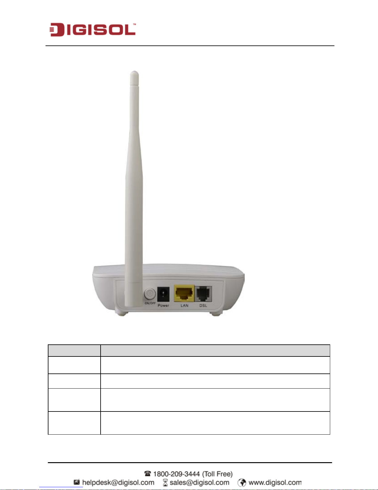
Rear Panel
The following table describes the interfaces of the device:
Items Description
On/Off Power switch. Power on or off the device.
Power
Power interface, for connecting to the power adapter of DC 12 V, 0.5 A, EU.
LAN
RJ-45 interface, for connecting to the Ethernet interface of PC or other
Ethernet devices through Ethernet cable.
DSL
RJ-11 i nter face, for connecting to the ADSL interface or a spli tter thr ough the
telephone cable.
Page 9
DG-BG1100N Use r Manual
9
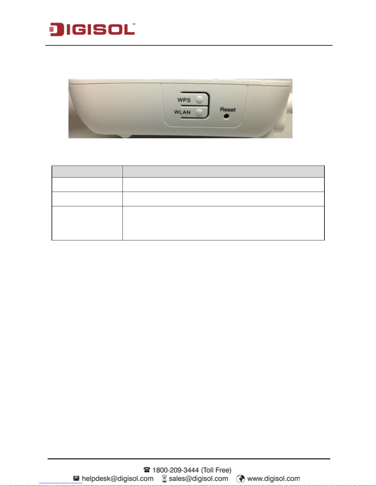
Side Panel
Items Description
WPS
Press the button to enable WPS.
WLAN
Press the button to enable WLAN.
Reset
Reset to the factory defaults. Keep the device powered on, then
insert a paper clip in t o the hole, pr ess and hol d for over 3 seconds.
The configuration will be reset to the factory defaults.
Page 10
DG-BG1100N Use r Manual
10
2 Hardware Installation
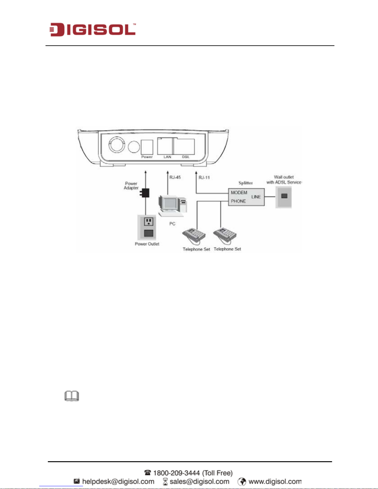
The follow ing figure shows the appli cation diagram for the connection of the router, PC, splitter
and the telephone sets, when no telephone set is placed before the splitter.
Step 1 Connect the DSL interface of t he device and t he Modem interfac e of the splitter
through a tel ephone cabl e. Connect the ph one to the Ph one interface of the s pl itter
through a cable. Connect the incoming line to the Line interface of the splitter.
The splitter has three interfaces:
•
Line: Connect to a wall phone jack (RJ-11 jack).
•
Modem: Connect to the ADSL jack of the device.
•
Phone: Connect to a telephone set.
Step 2 Connect the LAN interface of the de vice to the networ k card of the PC through an
Ethernet cable (MDI/MDIX).
Note: Use twisted-pair cables to connect with t he hu b or switch.
Step 3 Plug one end of t he power adapter to t he wall outlet and c onnect the other end to
the Power interface of the device.
Page 11
DG-BG1100N Use r Manual
11
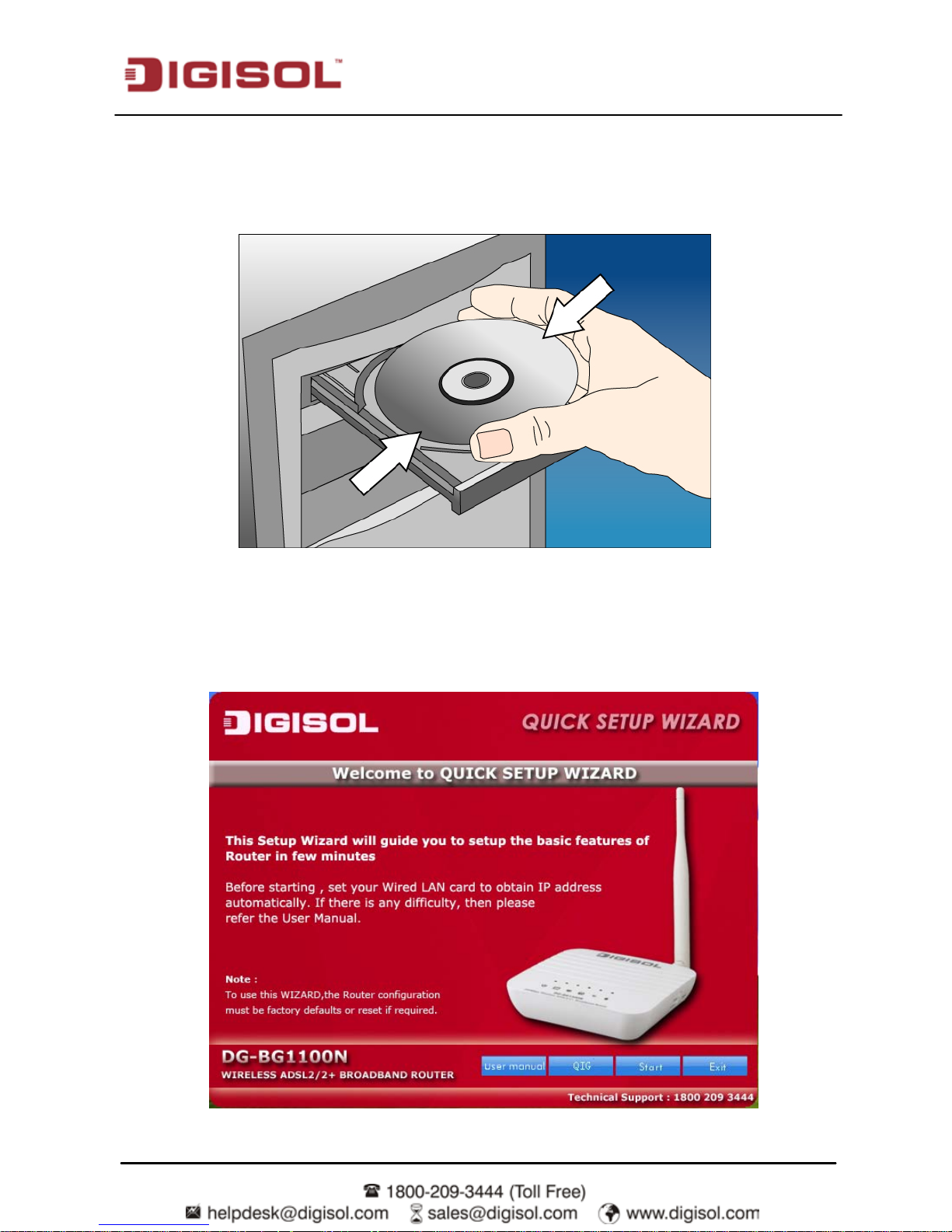
2.1 Software Installation
Insert the Setup CD into your CD-ROM drive of notebook/desktop computer.
Explore the CD and execute the “
DG-BG1100N.EXE
” file. Screen given below will be
displayed. Click ‘Start’ to continue.
Page 12
DG-BG1100N Use r Manual
12
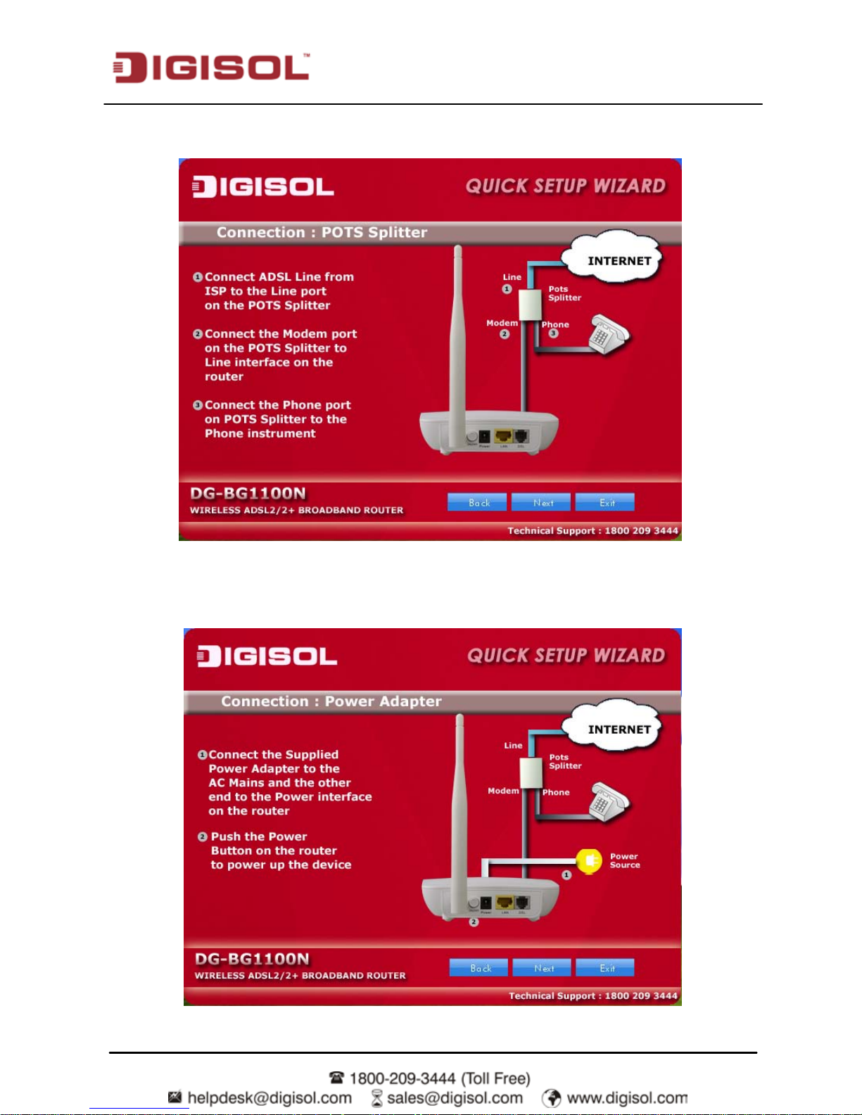
Connect the ADSL line to the router. Click ‘Next’.
Connect the power adapter to the AC Mains and the other end to the power interface on
the router. Push the power button on the router to power up the device.Click ‘Next’.
Page 13
DG-BG1100N Use r Manual
13
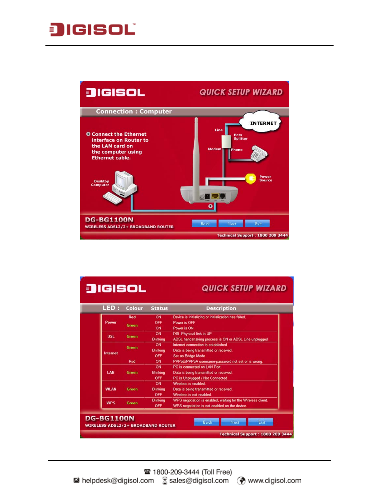
Connect the Etherne t i nter face on th e r outer to the LAN c ard on th e c om puter usi ng the
Ethernet cable. Click ‘Next’.
After powering up the ro uter, veri f y the status of th e LED indi c ators on the fron t panel of
the router. Click ‘Next’.
Page 14
DG-BG1100N Use r Manual
14
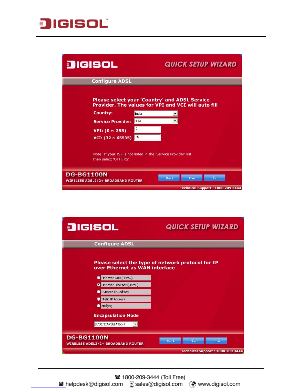
Please select your ‘Country’ and ADSL service provider. VPI and VCI values will auto fill.
Select the network protocol for WAN interface. Click ‘Next’.
Page 15
DG-BG1100N Use r Manual
15
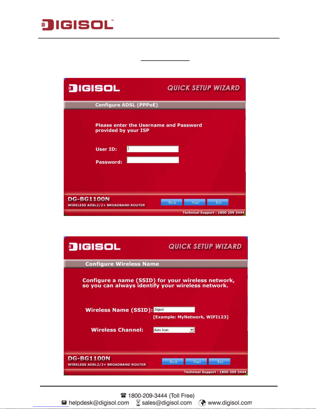
All the utility installation steps till here are the common steps to be followed for the modes.
Following are the steps for configuring
PPPoE connection
Enter the username and password provided by your ISP. Click ‘Next’.
:
Configure a wireless name (SSID) for your router. Click ‘Next’.
Page 16

DG-BG1100N Use r Manual
16
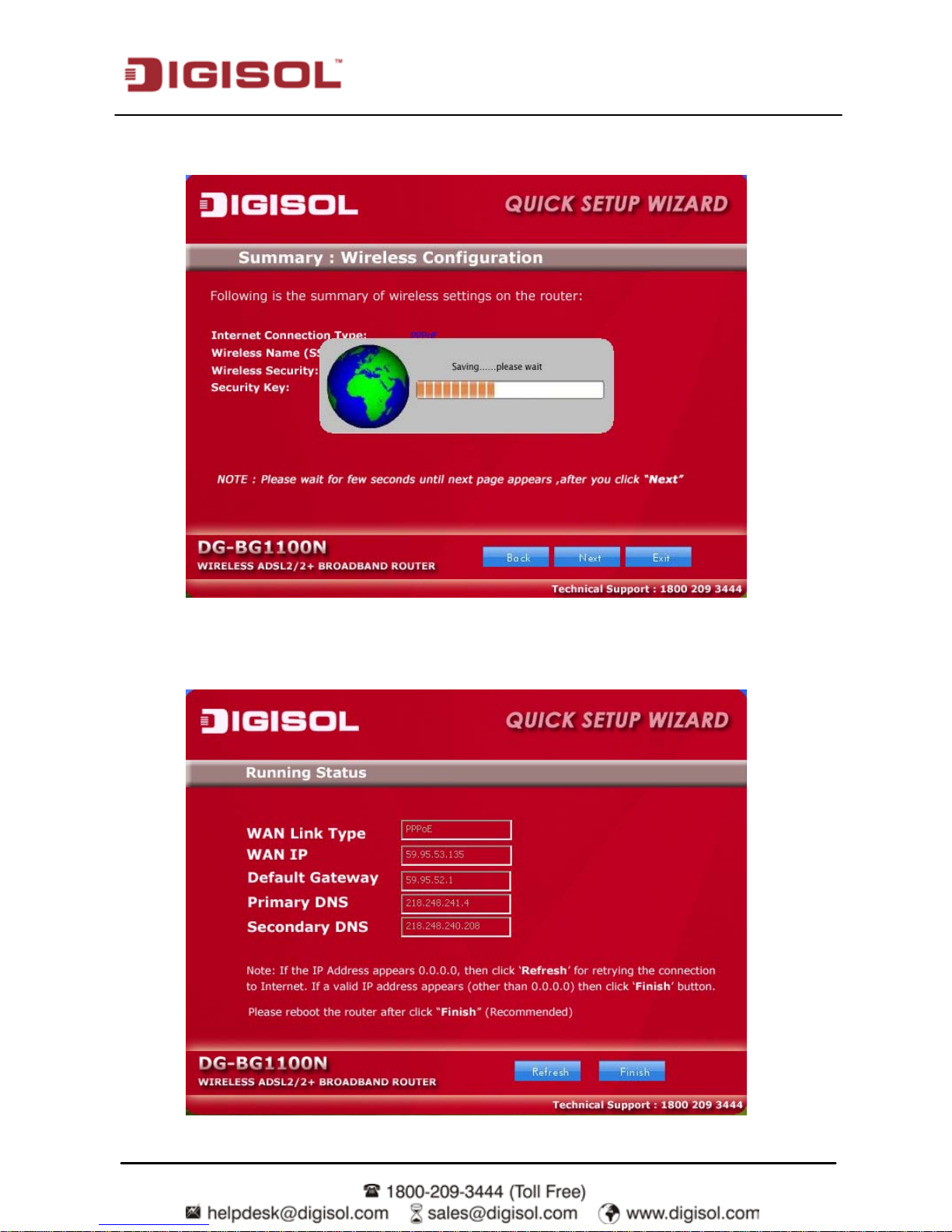
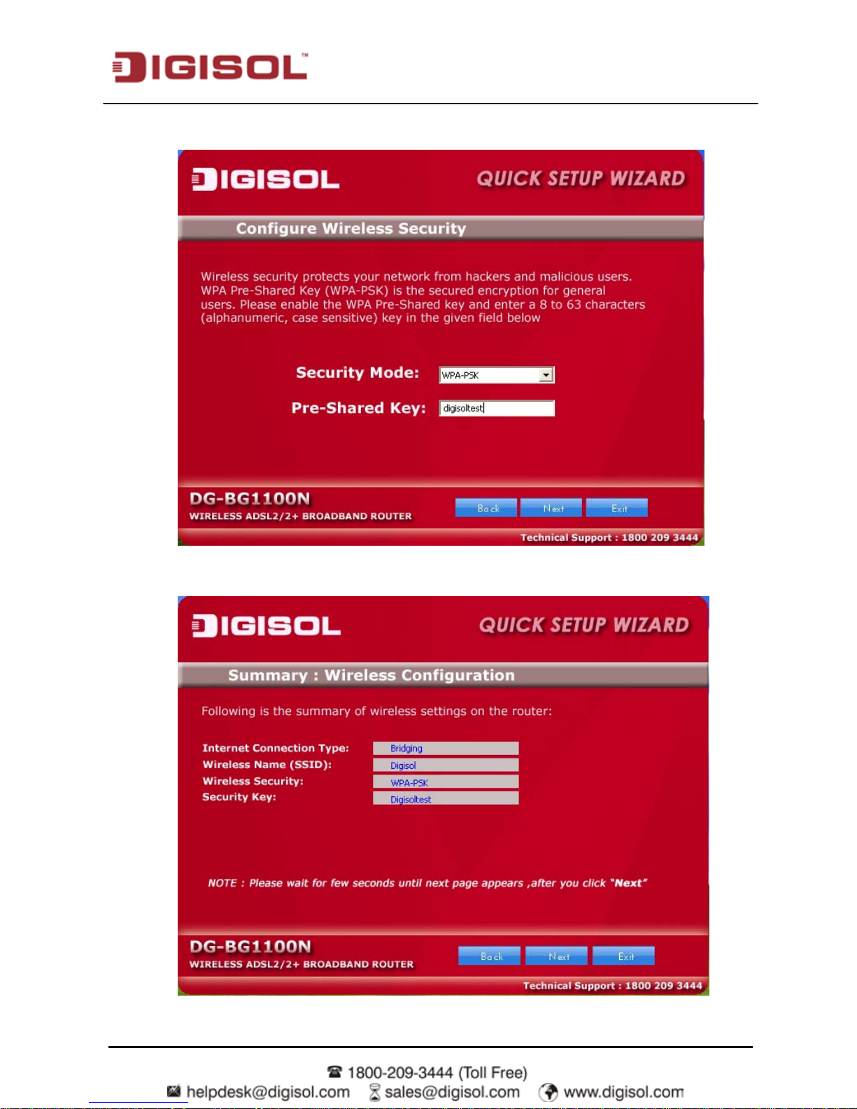
Configure the wireless security for your router. Click ‘Next’.
A screen with the summary of wireless setting will appear as shown below. Click ‘Next’.
Page 17
DG-BG1100N Use r Manual
17
Click on ‘Next’, the following screen will appear.
Once the connection is established, the router connection status will appear.
Page 18
DG-BG1100N Use r Manual
18
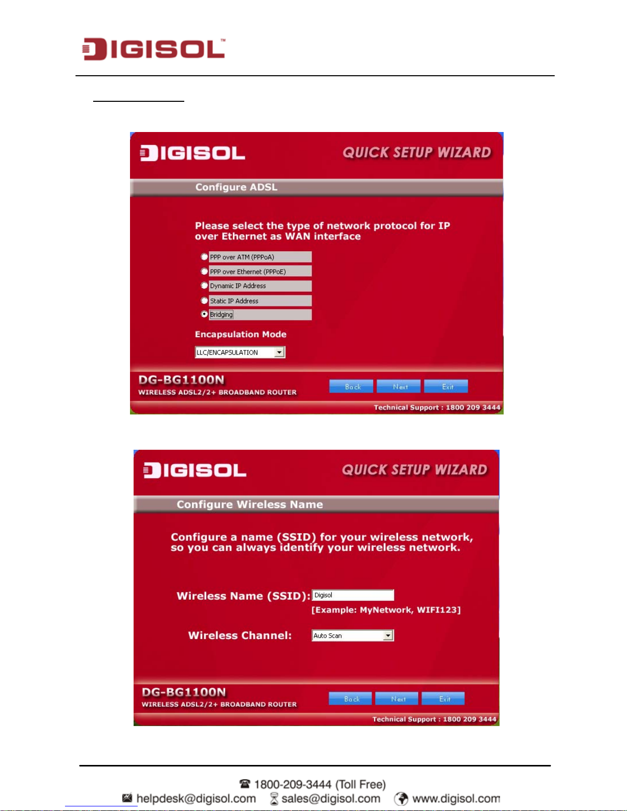
To configure the router in bridge mode select “Bridging” option. Click ‘Next’.
Bridging Mode:
Configure a wireless name (SSID) for your router. Click ‘Next’.
Page 19
DG-BG1100N Use r Manual
19
Configure the wireless security for your router. Click ‘Next’.
A screen with the summary of wireless setting will appear as shown below.
Page 20
DG-BG1100N Use r Manual
20
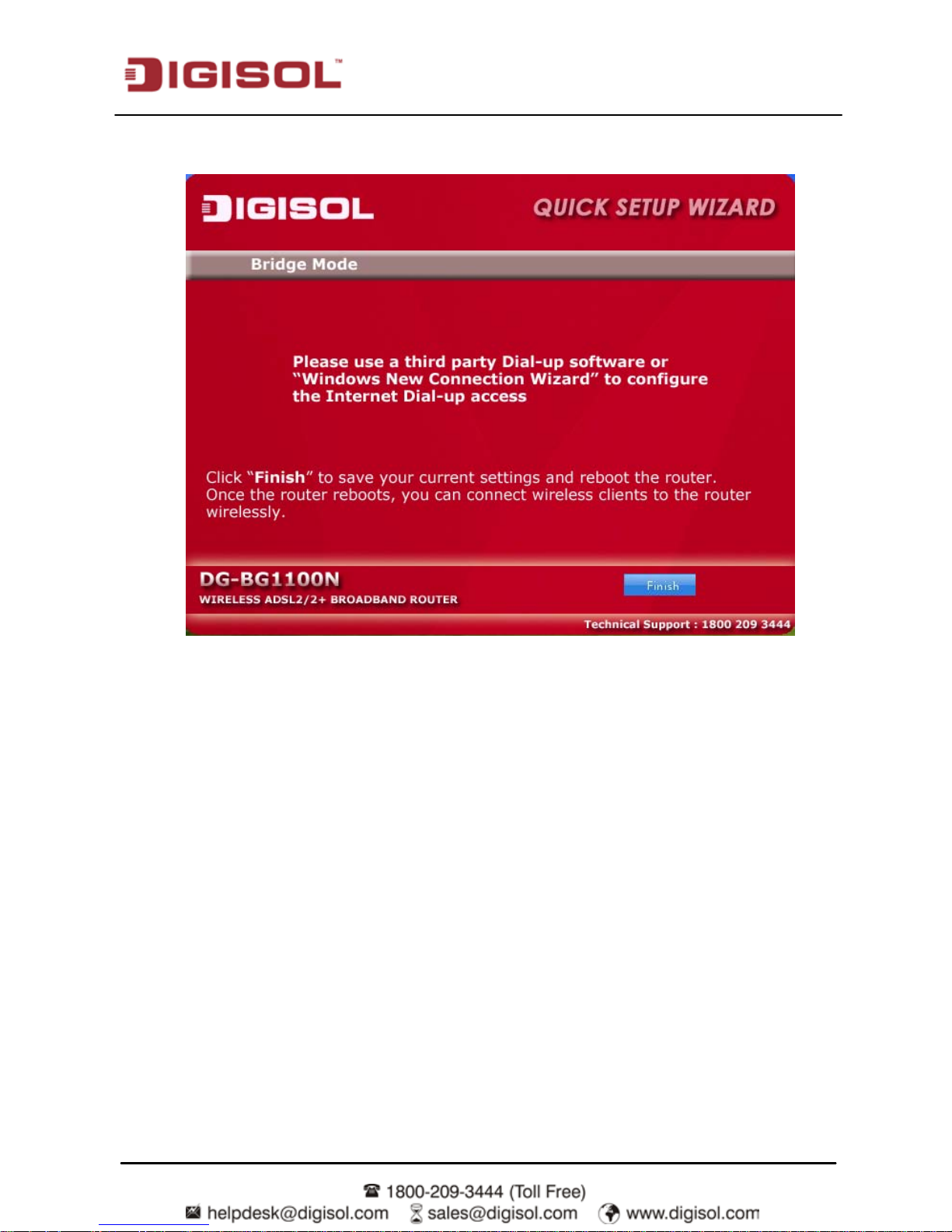
Click on ‘Next’ the following screen will appear.
Click on ‘Finish’ to complete the configuration of the router in Bridge mode.
Page 21
DG-BG1100N Use r Manual
21
2.2 PC Network Configuration
Each network interface on the PC should either be configured with a statically defined IP
address and DN S addr ess, or be ins tructed to aut omaticall y obtai n an IP addres s using the
network DHCP ser ver. DSL router pr o vides a DHC P ser ver on i ts LAN and i t i s recomm ended
to configure your LAN to automatically obtain its IP address and DNS server IP address.
The configur ation pri nciple is i dentical but shoul d be carr ied out differentl y on each oper ating
system.
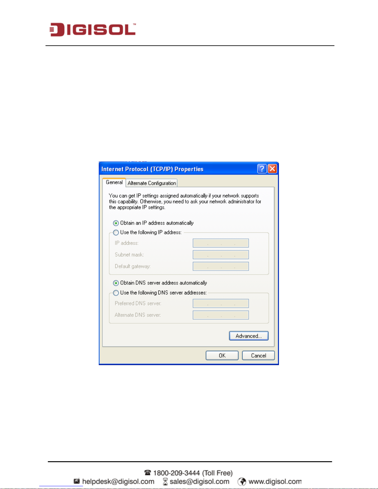
The following screen displays the TCP/IP Properties dialog box on Windows XP.
IP and DNS configuration
Page 22

DG-BG1100N Use r Manual
22
TCP/IP configuration steps for Windows XP are as follows:
Step 1 Choose Start > Control Panel > Network Connections.
Step 2 Right-click the Ethernet connection icon and choose Properties.
Step 3 On the General tab, select the Internet Protocol (TCP/IP) component and click
Properties.
Step 4 The Internet Protocol (TCP/IP) Properties window appears.
Step 5 Select the Obtain an IP address automatically radio button.
Step 6 Select the Obtain DNS server address automatically radio button.
Step 7 If you want to set the IP address and subnet mask manually, you can set the IP
address and subnet mask of the computer to 192.168.1.x and 255.255.255.0
respectively. The range for x is from 2 to 254.
Step 8 Click OK to save the settings.
Page 23
DG-BG1100N Use r Manual
23
3 Accessing the Internet
3.1 Accessing the Internet by Wireless Connection
By default, the wireless network of the wireless router is enabled. If you use a wireless network
adapter, do as follows to establish the connection:
Step 1 Turn on the Router. The WLAN is enabled by default.
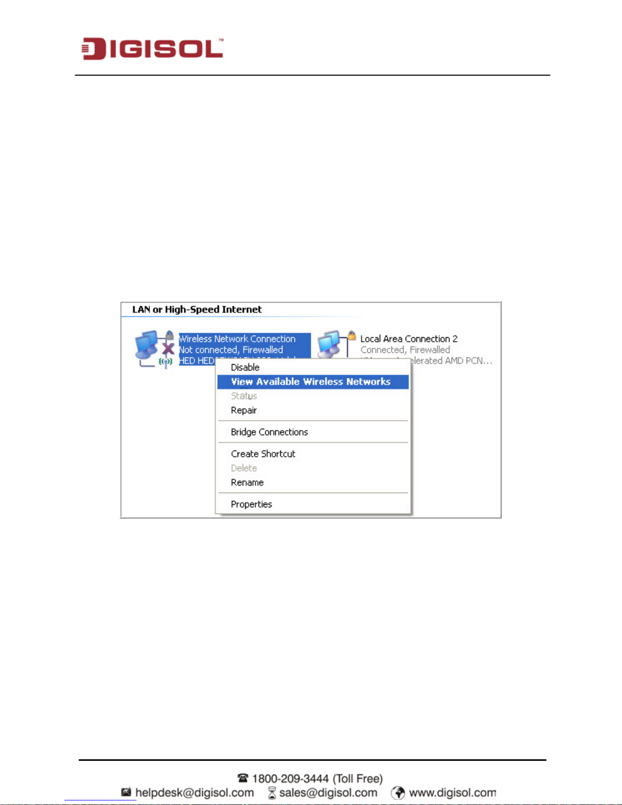
Step 2 Enable the wireless network adapter on your PC and ensure that the Wireless
Zero Configuration tool is available. Right-click the Wireless Network
Connection icon and choose View Available Wireless Networks from the menu.
Page 24

DG-BG1100N Use r Manual
24
Step 3 In the Wireless Network Connection page, click Refresh network list and the
network list is refreshed. Select the SSID of the router.
Step 4 Click Connect, enter the username and password in the pop-up window and start
connecting.
Page 25

DG-BG1100N Use r Manual
25
3.2 Accessing the Internet in Bridge Mode
This method is generally used when the Router works as a bridge. If you select this method for
accessing the network, you need to install and configure the dial-up software on your computer.
In addition, you need to perfor m dial-up oper ations on your com puter upon each startup. To
configure the Router and your computer for the network access, do as follow:
Step 1 Install and configure the PPP dial-up software on your computer.
Step 2 The PPP dial -up software i s pre-installed on certai n com puter operating s ystems .
To Create a dial-up con nection, do as follow s: (taking the W indows XP opera ting
system as an example)
Step 3 Choose Start > All Programs > Accessories > Communications > Network
Connections.
Step 4 Clic k Create a new conn ection in Networ k Tasks to di splay the New Connecti on
Wizard window, and then click Next.
Step 5 Select Connect to the Internet, and then click Next.
Step 6 Select Set up my connection manually, and then click Next.
Step 7 Select Connect using a broadband connection that requires a user name and
password, and then click Next.
Step 8 Enter the Name (as desired) of the dial-up connection in ISP Name, and then click
Next.
Step 9 Select anyone’s use or my use only, and then click Next.
Step 10 Enter the user name and password used for the dial-up connection provided by the
ISP (network operator), and then click Next.
Step 11 Select Add a shortcut to this connection to my desktop, and then click Finish.
Step 12 An icon for the dial-up connection is displayed on the desktop of your computer.
You need to perform the preceding operations only once for creating a network connection. To
access the internet, double-click the icon, and then click Connect in the displayed dialog box.
Page 26

DG-BG1100N Use r Manual
26
4 Web Configuration
This section describes how to configure the router by using the Web-based configuration utility.
4.1 Access the Router
The following is the detailed description of accesing the router for the first time.
Step 1 Open the Internet Explorer (IE) browser and enter http://192.168.1.1.
Step 2 In the Login page that is displayed, enter the username and password.
•
The username and password of the super user are admin and admin.
If you log i n, the pa ge shown in th e following fi gure appears. You can chec k, configure and
modify all the settings.
Page 27

DG-BG1100N Use r Manual
27
4.1.1 Status
In the navigation bar, click Status. In the Status page that is di splayed c ontains Device Info,
System Log and Statistics.
4.1.2 Device Info
Choose Status > Device Info. This page displays the current information for the ADSL Router.
It will display the Firmware version; LAN, WAN and MAC address information.
Page 28

DG-BG1100N Use r Manual
28
4.1.3 S yst em Log
Choose Status > System Log, the page shown in the f ollowing figure appears. The ADSL
Router keeps a running log of e vents and acti vities occ urring on the Router. If the d evice is
rebooted, the logs are automatically cleared.
4.1.4 Statistics
Choose Status > Statistics. The Statistics page that i s dis played contains Ethernet Statistics
and ADSL Statistics.
The ADSL Router keeps statistic of traffic that passes through it. You are able to view the
amount of packets th at pass through t he R outer on both the WAN port and th e LAN port. The
traffic counter will res et if the device is rebooted. You can selec t Ethernet/A DSL to view the
statistics report of LAN/WAN.
Page 29

DG-BG1100N Use r Manual
29
Ethernet Statistic
Click Ethernet in the Traffic Staticstics page, the page shown in the following figure appears. In
this page, you can view the s tatistics suc h as total Bytes, Col lisi on, Error Fram es and CRC
Errors.
ADSL Statistic
Click ADSL in the T raffic Staticstics page, the page s hown i n the fol lowing fi gur e appears . In
this page, you can view the ADSL line statistics such as total PDUs and total Error Counts.
Page 30

DG-BG1100N Use r Manual
30
WLAN Statistic
Click WLAN in the Traffic Statistics page, the page shown in the following figure appears. In this
page, you can view the WLAN statistics such as total PDUs, total Errors Count and total Drops
Count.
4.2 Quick Start
The Quick Start page will guide you to configure the ADSL router to connect to your ISP
(Internet Service Provider). The following sections describe these various configuration
parameter s. Whether you confi gure these parameter s or use t he defa ult ones , cli ck NEXT to
enable your Internet connecti on.
When s ubscribing to a br oadban d ser vice, you shoul d be aware of the metho d by whi ch you
are connected to t he Internet. T he technic al infor mation about the properties of your Internet
connection is provided by your Internet s er vice provider ( ISP). For e xample, your ISP shoul d
inform you whether you are connected to the Internet using a static or dynamic IP address, and
the protocol that you us e to communicate on the Internet.
In the navigation bar, click Quick Start. The page as shown in the following figure appears.
Page 31

DG-BG1100N Use r Manual
31
Click RUN WIZARD, a new pop up page as shown in the following figure appears.
Click EXIT, this page will be closed. Cli ck NEXT, the page as shown in the foll owing figure
appears.
Page 32

DG-BG1100N Use r Manual
32
In t his page, you can m odi f y the adm i n ac count’s password, a nd you c an m ake i t bl ank i f you
do not want to change it.
Click NEXT, the page as shown in the following figure appears.
In t his page, you can select a local time zone.
Click NEXT, the page as shown in the following figure appears.
Page 33

DG-BG1100N Use r Manual
33
There are four WAN connection types: Dynamic IP Address, Static IP Address, PPPoE/PPPoA
and Bridge Mode. Select the appropriate WAN connection type which is provided by your ISP.
For exampl e, if you subsc ribed PPPoE or PPPoA service from your ISP, you c an select the
PPPoE/PPPoA. Click NEXT, and the page as shown in the following figure appears.
Page 34

DG-BG1100N Use r Manual
34
We set the param eters of this page based on PPPoE protoc ol as an e xample shown i n the
following figure.
1) Enter the Username and Password provided by your ISP (Internet Service Provider).
2) Enter the VPI and VCI values pro vided by your ISP.
3) Select the connec ti on t ype accordi ng to the infor m ati on that your ISP provides to you. It
is common to set it to be PPPoE LLC.
After setting, click NEXT, the page as shown in the following figure appears.
Page 35

DG-BG1100N Use r Manual
35
In this page, you can enable or disabl e WLAN, change the W LAN SSID and authentication
type.
The configuration of six authentication types is introduced as below.
Disabled
When the authentication type Disabled is selected, the following figure will appear. Click NEXT
for the next step.
Page 36

DG-BG1100N Use r Manual
36
WEP-64Bits
When the authe nticati on type WEP-64Bits i s selec ted, the followi ng figure wil l appear. Enter 5
character s or 10 h e xadeci m al digits ("0-9", " A-F ") prec eded b y “0 x” for each K e y (1-4), and then
click NEXT for the next step.
Page 37

DG-BG1100N Use r Manual
37
WEP-128Bits
When the authe nt ic ati on t ype WEP-128Bits is s elec ted, the fol l owi ng figur e wi ll appear. Enter
13 char acter s or 26 hexadecim al digi ts ("0-9", "A-F") preceded b y “0x” for eac h Key (1-4), and
then click NEXT for the next step.
Page 38

DG-BG1100N Use r Manual
38
WPA-PSK
When the authent ic ati on t ype WPA-PSK is selected, the fol l owi ng figur e will appear. Select an
encryption from TKIP AES, TKIP and AES; enter a pre-shared key of 8~64 characters, and then
click NEXT for the next step.
Page 39

DG-BG1100N Use r Manual
39
WPA2-PSK
When the authentication type WPA2-PSK is selected, please refer to the WPA-PSK part for
configuration.
WPA-PSK/WPA2-PSK (Mixed mode)
When the authentication type WP A-PSK/WPA2-PSK (Mixed mode) is selected, please refer to the
WPA-PSK part for configuration.
Click BACK to modify the settings.
Click NEXT to save the settings.
Click EXIT to cancel the settings.
For D ynami c IP Address and Static IP Address, pl ease set the param eters ac cording to the
information provided by your ISP, and then follow the Wizard to finish the configuration.
Under Bridge mode, if you want to acc ess the internet , you need to dial-up w ith the correct
username and password provided by your ISP by using built-in dial-up software on your
computer. For the operation, please refer to
section 3.2
accessing the Network via PPP
Dial-Up.
Page 40

DG-BG1100N Use r Manual
40
4.3 Int er f ace Set up
In the navigation bar, click Interface Setup. The Interface Setup page that is displayed
contains Internet, LAN and Wireless.
4.3.1 Internet
Choose Interface Setup > Internet. Select PPPoA/PPPoE encapsulation.
Click Internet pane, the page shown in the following figure appears. In this page, you can
configure WAN interface of your router.
Page 41

DG-BG1100N Use r Manual
41
The following table describes the parameters of this page:
Field Description
V irtual Circuit
You can select a virtual circuit from the drop-list. Click PVCs
Summary to view the eight PVCs (from PVC0 to PVC7). Only
PVC0 is activated by default.
Status
You can select Activated or Deactivated for the selected virtual
circult.
VPI
The virtual pat h between two poi nts in an AT M networ k, ranging
from 0 to 255.
VCI
The virtual channel between two points in an ATM network,
ranging from 1 to 65535.
ATM QoS
The QoS category of the PVC. You can choose UBR, CBR,
nrt-VBR or rt-VBR.
PCR
Peak cell rate (PCR) is the maximum rate at which cells can be
transmitted along a connection in the ATM network. Its value
ranges from 1 to 65535.
SCR
Sustain cel l rate ( SCR) is the maximum rate that traffic c an pass
over a PVC without the r is k of cel l loss . Its value ranges from 0 to
65535.
MBS
Maximum burs t size (MBS) is the maximum number of cells that
can be transmitted at the PCR. Its value ranges from 0 to 65535.
IP Version
The IP Protocol you adopt ed. You can choose IPv4/IPv6, IPv4 or
IPv6.
ISP
Select the connec ti on m ode pro vide d b y your ISP. Ther e are four
options avaialbe: Dynamic IP Address, Static IP Address,
PPPoA/PPPoE or Bri dge Mode.
Servicename You can set the service name.
Username
Enter the us ernam e for PPPo E dial -up, w hic h i s pr ovided b y your
ISP.
Password
Enter the passwor d for PPPoE dial-up, whi ch is provided b y your
ISP.
Encapsulation
You can choose PPPoE LLC, PPPoE VC-Mux, PPPoA LLC or
PPPoA VC-Mux.
Page 42

DG-BG1100N Use r Manual
42
Bridge Interface You can choose Activated or Deactivated.
Connection
To control the time of c onnecting t o the internet. You can choose
Always On (Recommended), Connect On-Demand (Cl ose if idle
for xx minutes) or Connect Manual ly.
TCP MSS Option
You can keep the default value 0 or set a tcp mss value. The
range is from 100 to 1452.
Default Route
Choose the cur rent PVC as the default P VC, and it works i n the
routing mode. You can enable or disable default route.
Get IP Address You can choose Static or Dynamic.
Static IP Address
When Static is sel ec ted, you can enter the IP address for dial -up,
which is provided by your IS P.
IP Subnet Mask
When Static is selected, you can enter the IP subnet mask for
dial-up, which is provided by your ISP.
Gateway
When Static is sel ected, you can enter the gat ew a y I P for dial -up,
which is provided by your ISP.
NAT
Select it to ena bl e Networ k Addr es s T ranslati on ( NAT) function. If
you do no t s el ect i t and you w ant to acc es s the Intern et norm al l y,
you must add a route on the uplink equipment. Otherwise, the
access to the Internet fails. Normally, it is enabled.
TCP MTU Option
You can keep the default value 0 set a TCP MTU value. The range
is from 100 to 1500.
Dynamic Route You can select RIP1, RIP2-B and RIP2-M.
Direction You can select None, Both, IN Only and OUT Only.
Multicast
You can choose Disabled or Internet Group Management Protocol
(IGMP) v1, IGMP v 2 o r I GMPv3.
Clic k PVCs Summary besi des the fi eld Virtual Cir cuit, and the f ollowing fi gure appears. You
can view the information summary of each PVC.
Page 43

DG-BG1100N Use r Manual
43
If your IS P provides you an IP address automati call y, you ma y select Dynamic IP in the ISP
encapsul ation. Dynamic IP is typicall y used for Cabl e services. Pleas e enter the Dynamic IP
information accordingly.
Page 44

DG-BG1100N Use r Manual
44
The following table describes the parameters of this page:
Field Description
Encapsulation
You can choos e 1483 Bridged IP LLC , 1483 Bridged I P
VC-Mux, 1483 Routed IP LLC( IPoA) or 14 83 Routed IP
VC-Mux.
Bridge Interface for PPPoE You can choose Activated or Deactivated.
Default Route
You can enable or disable the default route. If you enable
this func tion, the c ur rent PVC wi ll be the defaul t gatew a y
to internet from this device.
TCP MTU Option
You can set a TCP MTU value. T he range i s fr om 100 to
1500. The default is 0.
NAT
Select it to enable Network Address Translation (NAT)
function. If you do not select it but want to access the
Internet normally, you must add a route on the uplink
equipment. Otherwise, the access to the Internet fails.
Normally NAT is enabled.
Dynamic Route
Select this option to specify the Routing Information
protocol (RIP) version. You can sel ect RIP1, RIP2-B or
RIP2-M.
Direction
You can select None, Both, IN Only or OUT Only to
specify the RIP direction. None is for disabling the RIP
function. Both means the ADSL Router will periodically
send routing i nformation and accept routing information
then incorpor ate it into r outing table. IN only means the
ADSL router will only accept but will not send RIP packet.
OUT only means the ADSL r outer wil l onl y send but will
not accept RIP packet.
Multicast
IGMP (Internet Group Multicast Protocol) is a
session-layer protocol used to establish membership in a
multicast group. The ADSL Router s upports both IG MP
version 1 (IGMP-v1), IGMP-v2.Select Disabled to disable
it.
Page 45

DG-BG1100N Use r Manual
45
Select Static IP Address in the ISP encapsulation to set static IP information. You will need to
enter in the Connec tion type, IP address, subnet m as k and gatew a y address , provided to you by
your ISP. Each IP address entered in the fields must be in the appropriate IP form, which are four
IP octets separ ated b y a d ot ( x.x.x. x). T he Rou ter wi l l not acc ept the IP address i f i t i s not i n thi s
format.
The following table describes the parameters of this page:
Field Description
Encapsulation
You can choos e 1483 Bridged IP LLC, 1483 Bridged IP VC-Mux,
1483 Routed IP LLC(IPoA) or 1483 Routed IP VC-Mux.
Default Route You can enable or disable default route.
TCP MTU Option
You can set a t cp MT U value. The r ange is fr om 100 to 1500. T he
default is 0.
Static IP Address
You can enter the IP addr ess for di al -up, w hi c h is provided b y your
ISP.
IP Subnet Mask
You can enter the IP s ubnet mask for dial-up, whi ch is pr ovided by
your ISP.
Gateway
You can enter the gate way IP for dial-up, which is provided by your
ISP.
NAT
Select it to enable Network Addr ess Translation (NAT) function. If
you do not s elect it but want to acces s the Internet normally, you
must add a route on the uplink equipment. Otherwise, the access to
the Internet fails. Normally, it is enabled.
Dynamic Route You can select RIP1, RIP2-B or RIP2-M.
Direction You can select None, Both, IN Only or OUT Only.
Page 46

DG-BG1100N Use r Manual
46
4.3.2 LAN
Choose Interface Setup > LAN. The LAN page that is displayed contains Router Local IP,
DHCP Server, DNS, Radvd and DHCPv6. In this page, you can change IP address of the
router. The default IP address is 192.168.1.1, which is the private IP address of the router.
Page 47

DG-BG1100N Use r Manual
47
The following table describes the parameters of this page:
Field Description
IP Address
Enter the IP address of LAN interface. It is recommended to use an
address fr om a bloc k res er ved for pr ivate use. T hi s addres s bl oc k
is 192.168.1.1- 192.168.255.254.
IP Subnet Mask
Enter the subnet mask of LAN interface. The range of subnet mask
is from 255.255.0.0 to 255.255.255.254.
Dynamic Route Select the Dynamic Routing Protocol as required.
Direction You can select None, Both, IN Only or OUT Only.
Multicast Select the IGMP Multicat Protcol or Disable it.
IGMP Snoop
You may select Activated or Deactivated. After Activating this
function, the pac kets of the IG MP broadcast will not be sent to the
LAN interface not belonging to the group.
Mld Snoop
You may selec t Enabled or Dis abl ed. After Act ivating this func tion,
the packets of the MLD broadcast will not be sent to the LAN
interface not belonging to the group.
DHCP
You can choose Disabled, Enabled or Relay. If set to DHCP
Server, the router can assign IP addresses, IP default gateway and
DNS Servers to the host under Windows95, Windows NT and
other operation systems that support the DHCP client.
Starting IP Address The starting IP address for the DHCP server's IP assignment.
IP Pool Count The max user pool size.
Lease Time
The lease time determines the period that the host retains the
assigned IP addresses before the IP addresses change. The
default is 259200 seconds.
Physical Ports
Choose the Ethernet Interface for which you want to enable DHCP.
DNS Relay
You can choos e Use Auto Discovered DNS Ser ver Only or Us e
User Di sc overed DNS Ser ver Only. If you sel ec t Auto Di sc o vered,
the router accepts the firstly-received DNS assignment from one of
the PPPoA, PPPoE or MER enabled PVC(s) during the connection
establishment. If you select User Discovered, enter the IP
addresses of the primary and secondary DNS servers.
Radvd Enable
You may choose to enable or disable Radvd. The Router
Advertisement Daemon (radvd) is an open-source software
product that implements link-local advertisements of IPv6 router
addresses and IPv6 routing prefixes using the Neighbor Discovery
Protocol (NDP).
Page 48

DG-BG1100N Use r Manual
48
Radvd Mode You may choose Auto or Manual.
Auto Prefix Enable or Disable Autoprefix for Radvd.
RA Flags Set You may choose ManagedAddr or Other Config.
DHCP6 Server You may choose to enable or disable DHCP6 Server.
DHCP6 Mode You may choose Auto or Manual for the DHCP6 Mode.
Dynamic Host Configur ation Protocol (DHCP) all ows the indi vidual PC to obtai n the TCP/IP
configuration from the centralized DHCP server. You can configure this router as a DHCP
server or disable it. The DHCP server can assign IP address, IP default gat eway and DNS
server to DHCP cli ents. This router c an also act as a sur rogate DHCP server (DHCP proxy)
where it rel ays IP address ass i gnm ent from an ac tual DHCP server to c li ents . You can enabl e
or disable DHCP server or DHCP proxy.
In the DHCP field, choose Disabled, the page shown in the following figure appears.
Page 49

DG-BG1100N Use r Manual
49
In the DHCP field, choose Relay, the page shown in the following figure appears. Enter a
server IP address running on WAN side.
Page 50

DG-BG1100N Use r Manual
50
4.3.3 Wireless
Choose In terf ace S etup > Wireles s. T he page as show n in the fol l owi ng figur e appears . The
Wireless page contains Access Point Settings, 11n Settings, Multipl e SSIDs Settings, W DS
Settings and Wireless MAC Address Filter.
Page 51

DG-BG1100N Use r Manual
51
The following table describes the parameters of this page:
Field Description
Access Point You may choose Activated or Deactivated.
Channel
Countries apply their own regulations to both the allowable
channels , allowed users and ma xim um power le vels within these
frequency ranges.
Beacon Interval Beacon Interval range is from 20 to 1000.
RTS/CTS Threshold RTS/CTS Threshold range is from 1500 to 2347.
Fragmentation
Threshold
Fragmentation Threshold r ange are only even num bers between
256 and 2346.
DTIM
DTIM range is from 1 to 255. A delivery traffic indication message is
a kind of tra ffic i ndic ati on m essage (TIM) whic h infor m s the c lient s
of the presence of buffered multicast/broadcast data on the access
point.
Wireless Mode
Comply wi th th e IEEE 802.11b/g and IEE E802.11n standards . You
can select 802.11b, 802.11g, 802.11b+g, 802.11n, 802.11g+n or
802.11b+g+n.
Channel Bandwidth Supporting 20MHz/40MHz Dual Channel.
Extension Channel
You can set below the control channel or above the control
channel.
Guard Interval You can set 800 nsec or AUTO.
MCS You can set an MCS index between 0 and 7, or select AUTO.
SSID index Supporting only a root SSID to be modified
PerSSID switch Activate or Dectivate SSID switch.
SSID
The service set identificati on (SSID) is a unique name to identify
the router in the wireless LAN. You may modify the SSID.
Broadcast SSID
Select whether the rou ter broadc asts SS ID or not. You can s elect
Yes or No.
Select Yes, and the wireless client searches the router
through broadcasting SSID.
Select No to hide SSID, and the wireless client can not search
the SSID.
Page 52

DG-BG1100N Use r Manual
52
Use WPS
WPS technology allows new customers without a
previously-established account to securely connect to your network
at the Wi-Fi hotspot, create and pay for an account, and access the
Internet.
Authentication Type
You can set a type from Disabled, WEP-64Bits, WEP-128Bits,
WPA-PSK, WPA2-PSK, WPA-PSK/ WPA2-PSK.
Pre-Shared ke y
It is a s hared s ecr et shar ed betwe en wi r eles s de vices us ing s om e
secured channel.
WDS Mode
Wireless Distribution System or Wireless Bridge between 2 or more
AP's
WDS Encryption type You can select TKIP or AES.
WDS Key Type the secret key in hexadecimal or ASCII format.
Active Activate or deactivate Wireless MAC Address Filter.
Action
You can set Allow or Deny to make Wireless LAN station(s)
associ ation. This function c an be used to all ow or deny ac cess to
certain wireless clients based on their MAC Address.
Mac Address #1~8 You can set eight Mac Addresses at most.
Page 53

DG-BG1100N Use r Manual
53
4.4 Adv an ced Set u p
In the na vigation bar, click Ad vanced Setup. In the Advanced Setu p page that i s displayed
contains Firewall, Routing, NAT, VLAN and ADSL.
4.4.1 Firewall
Choose Advanced Setup > Firewall. The page shown in the following figure appears. You can
select t his option to autom aticall y det ect and block D enial of Service (DoS) attacks suc h as
Ping of Death, SYN Flooding, Port Scan and Land Attack.
4.4.2 Routing
Click Advanced Setup > Routing, the page shown i n the fol low ing fi gur e appears . It dis pl a ys
routing table information.
Page 54

DG-BG1100N Use r Manual
54
Click ADD ROUTE, the page shown in the following figure appears. This page is used to
configure the routing information. You may add, edit or drop the static route.
The following table describes the parameters and buttons of this page:
Field Description
Destination IP
Address
Enter the IP address of the destination device.
IP Subnet
Mask
Enter the subnet mask of the destination device.
Gateway IP
Address
You can enter th e IP address of the ne xt hop in t he IP route to th e
destination device, or bind with a PVC interface.
Metric The metric cost for the destination.
Announced in
RIP
This par ameter determines if the ADSL router will include the route
to this rem ot e n ode in i ts RIP broadc asts . If s et to Yes, t he r ou te t o
this remote node will be propagated to other hosts through RIP
broadcasts. If No, this route is kept private and is not included in RIP
broadcasts.
Page 55

DG-BG1100N Use r Manual
55
4.4.3 NAT
Choose Advanced Se tup > NAT. The page shown in the following figure appears. In this page,
you can set up the NAT (Network Address Translation) function for your ADSL router.
Beforehand, you should activate NAT function for a virtual circuit. Please
refer
to 4.3.1
Internet.
NAT is short for Network Address Translation. The Network Address Translation Settings
window allows you to share one WAN IP address for multiple computers on your LAN.
The following table describes the parameters and buttons of this page:
Field Description
V irtual Circuit Enter Virtual Circuit Index that you plan to setup for the NAT function.
NAT Status
This fi el d shows the c urr ent status of th e NAT functi on for th e c ur rent
VC.
Number of IPs
This field is to specify how many IPs are provided by your ISP for
current VC. You can select Single or Multiple. When you choose
Single, you can set DMZ or Virtual Server. When you choose Multiple,
You can set D MZ, Virtual Ser ver or IP Address Mapping ( for Multi ple
IP Service).
Note:
For VCs with single IP, they share the same DMZ and Virtual servers; for VCs with multiple IPs,
each VC can set D MZ and Virtual servers. Further more, for VCs wi th multiple IPs , they can
Page 56

DG-BG1100N Use r Manual
56
define the Address Mapping rul es; for VCs w ith s i ngle IP, s i nce the y have onl y one IP, there is
no need to individually define the Address Mapping rule.
Demili tarized Zone (DMZ) is used t o provide Inter net s er vices without sac ri fici ng unauthori zed
access to its local private network. Typically, the DMZ host contains devices accessible to
Internet tr affic, such as w eb (HTT P) servers, FT P servers, S MT P (e-m ail) s ervers and DNS
servers.
In the NAT page, choose DMZ, and the page shown in the following figure appears.
The following table describes the parameters of this page:
Field Description
DMZ Select Enable DMZ to enable this function.
DMZ Host IP
Address
Enter the specified IP Address for DMZ host on the LAN side.
In the NAT page, choose Virtual Server, and the page shown in the following figure appears.
The Virtual Server is the server or server(s) behind NA T (on the LAN), for example, Web server
or FTP server, that you can mak e visible to the outs ide world even though N AT makes your
whole inside network appear as a single machine to the outside world.
Page 57

DG-BG1100N Use r Manual
57
The following table describes the parameters of this page:
Field Description
Rule
The Virtual server rule for this VC. You can specify 10 rules in
maximum. All the VCs with single IP will use the same Virtual
Server rules.
Application
You can enter an application name, or select a name from the right
drop-list menu like FTP or TELNET .
Protocol
Choose the t rans port l a yer protoc ol . You can c hoose A LL, T C P or
UDP.
Start/End Port
Number
Enter the speci fi c Start and End Port number you want t o forw ard.
If it is one port o nly, you c an e nter th e End port n um ber the s am e
as Start port number. For example, if you want to set the FTP
Virtual server, you can set the start and end port number to 21.
Local IP Address Enter the IP Address for the Virtual Server in LAN side.
Page 58

DG-BG1100N Use r Manual
58
In the NAT p age, choos e I P Address Mapping (for Multiple IP Service), and the page shown
in the following figure appears. The IP Address Mapping rule is per-VC based (onl y for Multiple
IPs' VCs).
Select “Multiple” to unhide the IP address mapping page.
Page 59

DG-BG1100N Use r Manual
59
Entries i n thi s table allow you to c onfigure one IP pool for spec i fied s ource IP address from LAN,
so that one packet whose source IP is in range of the specified address will select one IP address
from the pool for NAT.
The following table describes the parameters of this page:
Field Description
Rule Index
The Virtual server rule index for this VC. You can specify 10
rules i n maximum . Al l the VCs wi th s ingl e IP will us e the sam e
Virtual Server rules.
Rule Type
Choose the One-to-One, Many-to-One, Many-to-Many
Overload, Many-to-Many No Overload, or Server.
Local Start/End
IP
Enter the local IP Addres s you plan to m ap to. Local Start IP is
the starting local IP address and Local End IP is the ending
local IP address. If the r ule i s for al l loc al IPs, then the Start I P
is 0.0.0.0 and the End IP is 255.255.255.255.
Public Start/End
IP
Enter the public IP Address you want to do NAT. Public Start IP
is the starting public IP address and Public End IP is the ending
public IP address . If you have a d ynamic IP, ent er 0.0.0.0 as
the Public Start IP.
4.4.4 VLAN
Choose Advanced Setup > VLAN, the page shown in the following figure appears.
Page 60

DG-BG1100N Use r Manual
60
Virtual LAN (VLAN) is a group of devices on one or more LANs that are configured so that they
can communicate as if they were attached to the same wire, when in fact they are located on a
number of di fferent LAN s egments . Because VL ANs are bas ed on l ogical instead of ph ysical
connecti ons, it is very fle xible for user/host m anagement, bandwi dth allocation and resour ce
optimization.
In the VLAN page, choose Activated and then Assign VLAN PVID for each Interface, and the
page shown in the following figure appears.
Each physical port has a def ault VID c alled PVID (Port VID). PV ID is assigned to untagged
frames or priority tagged fr am es ( frames with null (0) VID) recei ved on this port . You can set a
PVID for an ATM VC, Ethernet port or Wireless LAN.
Page 61

DG-BG1100N Use r Manual
61
In the VLAN page, choos e Activated and then Define VLAN Group, and the page shown i n
the following figure appears.
The following table describes the parameters of this page:
Field Description
VLAN Index Choose a vlan index from 1 to 8.
Active Choose to activate or deactive the current vlan settings.
VLAN ID VLAN ID is from 1 to 4094.
ATM VCs Supporting eight ATM VCs, which can be tagged.
Ethernet The Ethernet port can be tagged.
Wireless LAN You can add the Wireless port to the Vlan group.
Page 62

DG-BG1100N Use r Manual
62
4.4.5 ADSL
Click Advanced Setup > ADSL, the page shown in the fol lowing figur e appears. The ADSL
feature can be selec ted when you m eet the ph ysical connec tion problem . Please chec k the
proper settings with your Internet service provider.
The router supports these modulations: G.Lite, T1.413, G.DMT, ADSL2, ADSL 2 + and Auto-Sync
Up. The router negotiates the modulation modes with the DSLAM.
The following table describes the parameters and buttons of this page:
Field Description
ADSL Mode
Choose Auto Sync-Up, ADSL2+, ADSL2, G.DMT, T1.413 or
G.lite. The default is Auto Sync-Up.
ADSL Type
Choose ANNEX A, ANNEX I, ANNEX A/L, ANNEX M or
ANNEX A/I/J/L/M.
Page 63

DG-BG1100N Use r Manual
63
4.5 Access Management
In the navigation bar, click Access Management. The Access Management page that is
displayed contains ACL, Filter, SNMP, UPnP, DDNS and CWMP.
4.5.1 ACL
Choose Access Management > ACL, and the page shown in the fol lowing fi gure appears .
The us er may remotel y access the ADSL Router once s etting his IP as a Sec ure IP Address
through selected applications. With the default IP 0.0.0.0, any client would be allowed to
remotely access the ADSL Router.
The following table describes the parameters and buttons of this page:
Field Description
ACL Rule Index You can establish sixteen ACL rules at the most.
Active Click to enable or disable the rule.
Secure IP
Address
The rule is valid if the IP is in this range.
Application Supports Web, FTP, Telnet, SNMP, Ping or ALL.
Page 64

DG-BG1100N Use r Manual
64
Interface Supports WAN, LAN or Both.
Access control
Listing
Only the devices whose MAC addres ses are li sted in the Access
Control Listing can access the router.
4.5.2 Filter
Choose Access Managem ent > Filter, and the page shown i n the following figure appear s.
Select IP/MAC Filter type. The user can set IP/MAC Filter, Application Filter and URL Filter.
4.5.2.1 I P /MAC Filt er
Choose Access M anagem ent > Filt e r > IP /MAC Filter, and the page s hown i n the fol low ing
figure appears. The user can set different IP filter rules of a given protocol (TCP, UDP or ICMP)
and a specific direction (incoming, outgoing, or both) to filter the packets.
Page 65

DG-BG1100N Use r Manual
65
The following table describes the parameters and buttons of this page:
Field Description
Filter Type
Selection
Supports IP / MAC Filter, Application Filter and URL Filter .
IP/MAC Filter Set
Index
You can choose an IP / MAC Filter Set Index from 1 to 12.
Interface
You can select an interface from the eight PVCs or the LAN
interface.
Direction Choose Both, Incoming or Outgoing.
Rule Type Supports IP or MAC.
Source IP
Address
Enter the Source IP Address. 0.0.0.0 means don't care.
Port Number Enter the Port Number. 0 means don't care.
Destination IP
Address
Enter the Destination IP Address. 0.0.0.0 means don't care.
Protocol Supports TCP, UD P or IC MP.
4.5.2.2 Application Filter
Choose Access Management > Filter > Application Filter, and the page shown in the
followi ng figure appears. Select Appl ication Filter type. T he user can set Application rul es to
filter the ICQ, MSN, YMSG and Real Audio/Video packets.
Page 66

DG-BG1100N Use r Manual
66
The following table describes the parameters and buttons of this page:
Field Description
Application Filter Choose to activate or deactivate the Application Filter rule.
ICQ Set Allow or Deny ICQ packets.
MSN Set Allow or Deny MSN packets.
YMSG Set Allow or Deny YMSG packets.
Real Audio/Video Set Allow or Deny Real Audio/Video packets.
4.5.2.3 URL Filt er
Choose Access Management > URL Filter, and the page shown in the following figure
appears. Select URL Filter type. T he user can set URL rules to prevent the LAN users to
access the internet.
Page 67

DG-BG1100N Use r Manual
67
The following table describes the parameters and buttons of this page:
Field Description
Active Make URL Filter rule activated or deactivated.
URL Index Can set an URL Filter Index from 1 to 16.
URL Enter the URL that needs to be filtered.
4.5.3 SNMP
Choose Access M an agemen t > SN M P, the page s hown i n the fol low ing fi gure appear s . The
SN MP ( Sim ple Network Management Protocol) i s used for exchanging information between
network devices.
The following table describes the parameters of this page:
Field Description
Get Community Select to set the password for the incoming Get- and
GetNext requests from the management station.
Set Community Select to set the password for incoming Set requests fr om
the management station.
Trap Host When CPE configuration is changed, SNMP will send a
message to the Trap Host. If the Trap Host has a Trap
Server, the user will receive corresponding information.
Page 68

DG-BG1100N Use r Manual
68
4.5.4 UPnP
Choose Access Man agement > UPnP, the page shown in the f ollowi ng figure appears. This
page is used to configure the UPnP parameters.
UPnP (Uni versal Plug a nd Pla y) is a dis tributed, open networ king standard that us es T CP/IP
for simple peer-to-peer network connectivity between devices. An UPnP device can
dynamical l y join a network, obtai n an IP address, c on vey i ts capabil ities and learn about oth er
devices on the network. In turn, a device can leave a network smoothly and automatically when
it is no longer in use. UPnP broadcasts are only allowed on the LAN.
The following table describes the parameters of this page:
Field Description
UPnP You can choose Activated or Deactivated.
Auto-configured UPn P networ k devices c an automatical ly configure network
addressi ng, announc e their pres enc e in the netw ork t o other
UPnP devices and enable e xchange of si mple produc t and
service descriptions.
Page 69

DG-BG1100N Use r Manual
69
4.5.5 DDNS
Choose Access Management > DDNS, the page shown in the following figure appears.
The Dynamic Domain Name System (DDNS) lets you use a static host name with a dynamic IP
address. U ser should type the host name, user nam e and password assi gned to your ADSL
Router by your Dynamic DNS provider. The user also can decide to turn on DYNDNS Wildcard
or not.
The following table describes the parameters of this page:
Field Description
Dynamic DNS Choose to activate or deactivate DDNS function.
My Host Name The DDNS identifier.
E-mail Address The email provided by DDNS provider.
Username The name provided by DDNS provider.
Password The password provided by DDNS provider.
Wildcard support You can choose Yes or No.
Page 70

DG-BG1100N Use r Manual
70
4.5.6 CWMP
Choose Access Management > CWMP, and the page shown in the following figure appears.
The following table describes the parameters of this page:
Field Description
URL URL for the CPE to connect to the ACS using the CPE WAN
Management Prot ocol. T his param eter must be in the form of a valid
http or https url.
User
Name
Username used to authenticate the CPE when making a connection to
the ACS using the CPE WAN Management Protocol.
Password Pass wor d used to authenti c ate the C PE wh en m aking a connecti on to
the ACS using the CPE WAN Management Protocol.
UserName CPE’s username, the connection username provided by TR-069
service
Password CPE’s password, the connection password provided by TR-069
service for a connection request to the CPE.
Periodic
Inform
Select Activated to periodically connect to the ACS to check for
configuration updates.
Interval(s) Specify the duration between two connections to ACS.
Page 71

DG-BG1100N Use r Manual
71
4.6 Maintenance
In the navigation bar, click Maintenance. T he Maintenanc e page that is displayed contains
Administration, Time Zone, Firmware, SysRestart and Diagnostics.
4.6.1 Administration
Choose Maintenance > Administration, the page shown in the following figure appears.
There is only one account that can access Web-Management interface. The default account is
"admin", and the password is "1234". Admin has read/write access privilege. In this web page,
you can set new password for admin.
The following table describes the parameters of this page:
Field Description
New Password Enter the new password.
Confirm
Password
Re-enter the new password.
Page 72

DG-BG1100N Use r Manual
72
4.6.2 Time Zone
Choose Maintenance > Time Zone, the page shown in the following figure appears.
The s ystem tim e is the tim e used by the de vice for s chedul i ng ser vices. You c an m anuall y set
the time or connect to a NT P (Netw ork Tim e Protocol) server. If a NTP server i s set, you wi ll
only need to set the tim e zone. If you manually set the tim e, you may also s et Daylight Sa ving
dates and the system time will automatically adjust on those dates.
The following table describes the parameters of this page:
Field
Description
Synchronize time
with
You can choose NTP Server automatically, PC’s Clock or
Manually.
Time Zone
Choose the time zone (in which area you are) from the
drop-down list.
Daylight Saving You can enable the daylight saving time.
NTP Server Address Set the NTP server manually.
Page 73

DG-BG1100N Use r Manual
73
4.6.3 Firmware
Choose Maintenance > Firmware, the page shown in the following figure appears.
You can upgrade the fi r m ware of the Ro uter i n this page. Make sur e th e fir m ware you want to
use is on the loc al hard dri ve of the com put er. Cli ck on Brows e to brow se the loc al har d drive
and locate the firmware to be used for upgrade.
The following table describes the parameters of this page:
Field
Description
New Firmware
Location
Click browse to select the firmware file.
New Config Location Click browse to select the config file.
Config Backup
Click it, and select the path. Then you can save the
configuration file of the router.
UPGRADE
After selecting the file, click UPGRADE to start upgradi ng the
file.
Page 74

DG-BG1100N Use r Manual
74
4.6.4 SysRestart
Choose Maintenance > SysRestart, the page shown in the following figure appears. User can
restart the device with current settings or factory default settings.
The following table describes the parameters of this page:
Field
Description
Current Settings Save the current settings and then reboot the router.
Factory Default
Settings
Reset to the factory default settings and then reboot the
router.
Page 75

DG-BG1100N Use r Manual
75
4.6.5 Diagnostics
Choose Maintenance > Diagnostics, the page shown in the foll owing figure appears. This
page shows the test results for the connectivity of the physical layer and protocol layer for both
LAN and WAN sides.
The following table describes the parameters of this page:
Field
Description
Virtual Circuit Choose PVC from the drop down list to test.
Page 76

DG-BG1100N Use r Manual
76
4.7 Troubleshooting
If you encount er an y pr oblem when you’re us i ng this wi rel ess router, don’t pan ic . Before you cal l
your dealer of purchas e for hel p, please c heck thi s troubl eshooting s ection, the s olution of your
problem could be very simple, and you can solve the problem yourself.
Scenario Solution
All the indicators are off.
•
Check the connection between the power adapter
and the power socket.
•
Check whether the power switch is turned on.
The LAN indicator is off.
Check the following:
•
The connection between the device and your PC,
hub or switch.
•
The running status of the computer, hub, or switch.
The DSL indicator is not on.
Check the connection between the DSL port of the device and
the wall jack.
Internet access fails while the
ADSL indicator is on.
Check whether the VPI, VCI, user nam e and password are
correctly entered.
Failed to access the web
configuration page of the DSL
router.
Choose Start > Run from the desktop, and pi ng 192.168.1.1
(IP address of the DSL router). If the DSL router is not
reachable, check the type of the network cable, the
connection between the DSL router and the PC, and the
TCP/IP configuration of the PC.
Load the default settings after
incorrect configuration.
To restore the fac tor y default settings, turn on the de vice, and
press the r eset button for about 3 seconds, and then r elease
it. The default IP address a nd the subnet mask of the DSL
router are 192.168.1.1 and 255.255.255.0, respectively.
The username/password of admin user is admin/admin.
 Loading...