

Page 1
DG-WU2005V User Manual
DG-WU2005V
WIRELESS ACCESS CONTROLLER, 5GE
LAN, 2GE WAN, 1GE DMZ, USB
User Manual
V1.0
2015-08-26
As our products undergo continuous development the specifications are subject to change without prior notice
1
Page 2

DG-WU2005V User Manual
2
TABLE OF CONTENTS
CHAPTER 1 INTRODUCTION ................................................................................................... 8
1.1 PACKAGE CONTENTS .......................................................................................................................................................... 9
1.2 HARDWARE INSTALLATION ................................................................................................................................................ 9
1.2.1 ATTENTION .................................................................................................................... 9
1.2.2 SYSTEM REQUIREMENTS ............................................................................................ 10
1.2.3 Hardware Configuration .................................................................................................. 11
1.2.4 LED Indicators................................................................................................................ 12
CHAPTER 2 GETTING STARTED ........................................................................................... 13
2.1 CONNECT YOUR DEVICE .................................................................................................................................................. 13
2.2 EASY SETUP BY CONFIGURING WEB UI......................................................................................................................... 13
2.2.1 Wizard ........................................................................................................................... 14
2.2.1.1 Configure with the Network Setup Wizard............................................................................................... 14
2.2.1.2 Configure with the VPN Setup Wizard ..................................................................................................... 20
2.2.2 Status ................................................................................................ ............................ 26
2.2.2.1 Network Status ............................................................................................................................................. 27
2.2.2.2 LAN Client List...................................................................................................................................................... 29
2.2.2.3 Firewall Status.............................................................................................................................................. 29
2.2.2.4 VPN Status ................................................................................................................................................... 30
2.2.2.5 System Management Status...................................................................................................................... 31
2.2.2.6 DDNS Status ........................................................................................................................................................ 32
2.2.2.7 UPnP Status ......................................................................................................................................................... 33
2.2.2.8 Storage Status...................................................................................................................................................... 33
3.1 BASIC NETWORK ............................................................................................................................................................... 38
3.1.1 WAN Setup ................................................................ .................................................... 38
3.1.1.1 Physical Interface ........................................................................................................................................ 39
3.1.1.2 Internet Setup ............................................................................................................................................... 40
3.1.1.2.1 Ethernet WAN ............................................................................................................................................41
3.1.1.2.2 Wireless WAN – 3G/4G .............................................................................................................................50
3.1.1.3 Load Balance................................................................................................................................................ 51
3.1.2 LAN & VLAN .................................................................................................................. 54
3.1.2.1 Ethernet LAN ................................................................................................................................................ 54
3.1.2.2 VLAN.............................................................................................................................................................. 55
3.1.2.2.1 VLAN Scenarios ........................................................................................................................................56
3.1.2.2.2 Port-Based VLAN ......................................................................................................................................61
Page 3

DG-WU2005V User Manual
3
3.1.2.2.3 Tag-Based VLAN.......................................................................................................................................63
3.1.3 IPv6 Setup ................................................................................................ ..................... 66
3.1.3.1 6 to 4 .............................................................................................................................................................. 66
3.1.3.2 6 in 4 .............................................................................................................................................................. 67
3.1.4 NAT / Bridging................................ ................................................................ ................ 69
3.1.4.1 Configuration ................................................................................................................................................ 69
3.1.4.2 Virtual Server & Virtual Computer ............................................................................................................. 70
3.1.4.2.1 Virtual Server .............................................................................................................................................70
3.1.4.2.2 Virtual Computer........................................................................................................................................71
3.1.4.3 Special AP & ALG........................................................................................................................................ 71
3.1.4.3.1 ALG ...........................................................................................................................................................71
3.1.4.3.2 Special AP ..................................................................................................................................................72
3.1.4.4 DMZ ............................................................................................................................................................... 72
3.1.5 Routing ................................................................ .......................................................... 73
3.1.5.1 Static Routing ............................................................................................................................................... 73
3.1.5.2 Dynamic Routing.......................................................................................................................................... 75
3.1.5.3 Routing Information ..................................................................................................................................... 77
3.1.6 Client/Server/Proxy................................................................................................ ......... 78
3.1.6.1 Dynamic DNS ............................................................................................................................................... 78
3.1.6.2 DHCP Server................................................................................................................................................ 79
3.1.6.2.1 DHCP Server List ......................................................................................................................................79
3.1.6.2.2 DHCP Server Configuration ......................................................................................................................80
3.1.6.2.4 Fixed Mapping ...........................................................................................................................................82
3.2 ADVANCED NETWORK ...................................................................................................................................................... 83
3.2.1 Firewall ................................................................ .......................................................... 84
3.2.1.1 Configuration ................................................................................................................................................ 84
3.2.1.2 Packet Filters................................................................................................................................................ 84
3.2.1.2.1 Configuration .............................................................................................................................................85
3.2.1.2.2 Packet Filter List ........................................................................................................................................85
3.2.1.2.3 Packet Filter Rule Configuration ...............................................................................................................85
3.2.1.3 URL Blocking................................................................................................................................................ 87
3.2.1.3.1 Configuration .............................................................................................................................................87
3.2.1.3.2 URL Blocking Rule List ............................................................................................................................88
3.2.1.3.3 URL Blocking Rule Configuration ............................................................................................................88
3.2.1.4 Web Content Filters..................................................................................................................................... 89
3.2.1.4.1 Configuration .............................................................................................................................................89
3.2.1.4.2 Web Content Filter Rule List .....................................................................................................................90
3.2.1.4.3 Web Content Filter Configuration..............................................................................................................90
Page 4

DG-WU2005V User Manual
4
3.2.1.5 MAC Control ................................................................................................................................................. 91
3.2.1.5.1 Configuration .............................................................................................................................................91
3.2.1.5.2 MAC Control Rule List..............................................................................................................................92
3.2.1.5.3 MAC Control Rule Configuration .............................................................................................................92
3.2.1.6 Application Filters ........................................................................................................................................ 92
3.2.1.6.1 Configuration .............................................................................................................................................93
3.2.1.7 IPS.................................................................................................................................................................. 94
3.2.1.8 Options .......................................................................................................................................................... 94
3.2.2 QoS & BWM .................................................................................................................. 95
3.2.2.1 Configuration ................................................................................................................................................ 96
3.2.2.2 Rule-based QoS .......................................................................................................................................... 97
3.2.2.2.1 Configuration .............................................................................................................................................98
3.2.2.2.2 QoS Rule List.............................................................................................................................................99
3.2.2.2.3 QoS Rule Configuration...........................................................................................................................100
3.2.3 VPN Setup ................................................................................................................... 104
3.2.3.1 IPSec ........................................................................................................................................................... 105
3.2.3.1.1 IPSec VPN Tunnel Scenarios...................................................................................................................105
3.2.3.1.2 IPSec Configuration .................................................................................................................................107
3.2.3.1.3 Tunnel List & Status ................................................................................................................................108
3.2.3.1.4 Tunnel Configuration ...............................................................................................................................108
3.2.3.1.5 Local & Remote Configuration................................................................................................................109
3.2.3.1.6 Authentication ..........................................................................................................................................110
3.2.3.1.7 IKE Phase.................................................................................................................................................110
3.2.3.1.8 IKE Proposal Definition........................................................................................................................... 111
3.2.3.1.9 IPSec Phase ..............................................................................................................................................112
3.2.3.1.10 IPSec Proposal Definition ........................................................................................................................112
3.2.3.2 PPTP............................................................................................................................................................ 113
3.2.3.2.1 PPTP / L2TP VPN Tunnel Scenarios .......................................................................................................113
3.2.3.2.1 PPTP Server Configuration......................................................................................................................114
3.2.3.2.2 PPTP Server Status...................................................................................................................................115
3.2.3.2.3 User Account List.....................................................................................................................................115
3.2.3.2.4 User Account Configuration ....................................................................................................................116
3.2.3.2.5 PPTP Client ..............................................................................................................................................116
3.2.3.2.6 PPTP Client List & Status ........................................................................................................................116
3.2.3.2.7 PPTP Client Configuration ......................................................................................................................117
3.2.3.3 L2TP ............................................................................................................................................................ 118
3.2.3.3.1 L2TP Server Configuration......................................................................................................................118
3.2.3.3.2 L2TP Server Status...................................................................................................................................119
Page 5

DG-WU2005V User Manual
5
3.2.3.3.3 User Account List.....................................................................................................................................119
3.2.3.3.4 User Account Configuration ....................................................................................................................120
3.2.3.3.5 L2TP Client ..............................................................................................................................................120
3.2.3.3.6 L2TP Client List & Status ........................................................................................................................121
3.2.3.3.7 L2TP Client Configuration ......................................................................................................................121
3.2.3.4 GRE ............................................................................................................................................................. 123
3.2.3.4.1 GRE VPN Tunnel Scenario......................................................................................................................123
3.2.3.4.2 GRE Configuration ..................................................................................................................................123
3.2.3.4.3 GRE Tunnel Definition ............................................................................................................................124
3.2.3.4.4 GRE rule Configuration ...........................................................................................................................124
3.2.3.4.5 SSL VPN ........................................................................................................................................................125
3.2.4 Redundancy................................................................................................................. 126
3.2.4.1 VRRP ........................................................................................................................................................... 126
3.2.5 System Management ................................ ................................................................ .... 128
3.2.5.1 TR-069......................................................................................................................................................... 128
3.2.5.2 SNMP .......................................................................................................................................................... 128
3.2.5.3 Telnet with CLI ........................................................................................................................................... 130
3.2.5.4 UPnP............................................................................................................................................................ 131
3.2.6 Certificate ........................................................................................................................ 131
3.3 APPLICATIONS.................................................................................................................................................................. 133
3.3.1 AP Management........................................................................................................... 134
3.3.1.1 Configuration .............................................................................................................................................. 134
3.3.1.1.1 AP Management Configuration ...............................................................................................................134
3.3.1.1.2 AP Configuration Proposal List ...............................................................................................................134
3.3.1.2 AP List ......................................................................................................................................................... 135
3.3.1.2.1 Trusted AP List & Status..........................................................................................................................135
3.3.1.3 AP Configuration........................................................................................................................................ 136
3.3.1.3.1 AP Configuration............................................................................................................................................136
3.3.2 Captive Portal .............................................................................................................. 137
3.3.2.1 Captive Portal Configuration .................................................................................................................... 137
3.4 SYSTEM............................................................................................................................................................................. 138
3.4.1 System Related ................................ ............................................................................ 140
3.4.1.1 Change Password ..................................................................................................................................... 140
3.4.1.2 System Information.................................................................................................................................... 141
3.4.1.3 System Status ............................................................................................................................................ 141
3.4.1.4 System Tools.............................................................................................................................................. 142
3.4.2 Scheduling ................................................................................................................... 145
3.4.3 User Management ................................................................ ........................................ 146
Page 6

DG-WU2005V User Manual
6
3.4.3.1 User List ...................................................................................................................................................... 147
3.4.3.2 User Profile ................................................................................................................................................. 147
3.4.3.3 User Group ................................................................................................................................................. 148
3.4.4 Grouping................................................................ ...................................................... 149
3.4.4.1 Grouping Configuration............................................................................................................................. 149
3.4.4.2 Host Grouping ............................................................................................................................................ 149
3.4.4.2.1 Host Group List........................................................................................................................................149
3.4.4.2.2 Host Group Configuration .......................................................................................................................150
3.4.4.3 File Extension Grouping ........................................................................................................................... 151
3.4.4.3.1 File Extension Group List ........................................................................................................................151
3.4.4.3.2 File Extension Group Configuration........................................................................................................151
3.4.4.4 L7 Application Grouping ........................................................................................................................... 152
3.4.4.4.1 L7 Application Group List .......................................................................................................................152
3.4.4.3.2 L7 Application Group Configuration .......................................................................................................152
3.4.5 External Servers........................................................................................................... 153
3.4.5.1 External Server List ................................................................................................................................... 153
3.4.5.2 External Server Configuration.................................................................................................................. 154
3.4.6 MMI ............................................................................................................................. 155
3.4.6.1 Web UI......................................................................................................................................................... 155
CHAPTER 4 TROUBLESHOOTING ...................................................................................... 156
Page 7

DG-WU2005V User Manual
7
Copyright
Copyright 2015 by Smartlink Network Systems Ltd. All rights reserved. No part of this
publication may be reproduced, transmitted, transcribed, stored in a retrieval system, or translated
into any language or computer language, in any form or by any means, electronic, mechanical,
magnetic, optical, chemical, manual or otherwise, without the prior written permission of this
company.
This company makes no representations or warranties, either expressed or implied, with respect to
the contents hereof and specifically disclaims any warranties, merchantability or fitness for any
particular purpose. Any software described in this manual is sold or licensed "as is". Should the
programs prove defective following their purchase, the buyer (and not this company, its distributor,
or its dealer) assumes the entire cost of all necessary servicing, repair, and any incidental or
consequential damages resulting from any defect in the software. Further, this company reserves
the right to revise this publication and to make changes from time to time in the contents thereof
without obligation to notify any person of such revision or changes.
Trademarks:
DIGISOL™ is a trademark of Smartlink Network Systems Ltd. All other trademarks are the
property of the respective manufacturers.
Safety
This equipment is designed with the utmost care for the safety of those who install and use it.
However, special attention must be paid to the dangers of electric shock and static electricity when
working with electrical equipment. All guidelines of this and of the computer manufacturer must
therefore be allowed at all times to ensure the safe use of the equipment.
Page 8

DG-WU2005V User Manual
8
Chapter 1 Introduction
Congratulations on your purchase of this outstanding product: DG-WU2005V Multi-Service
Gateway with WLAN Controller. The product series, the multi-service security gateway comes
with fruitful functions to meet SMB fast growing intranet access requirement. Multi-WAN NAT
function allows multiple clients to have high speed access. VPN technology can enable secure
access within intranet. By AP controller function, it is easy to deploy WiFi access infrastructure.
Firewall and access control can prevent from hackers attack and avoid unproductive activity.
Friendly setting and professional network management function, supervisor can easily take control
of whole intranet. Besides being used for SMB corporate, when combined with various gateway
series, it is also quite suitable for commercial, mobile office, hotspot deployment, and M2M-IoT
application. For optimal IT investment, this device will guarantee maximum ROI and highest
reliability.
Instructions for installing and configuring this product can be found in this manual. Before you
install and use this product, please read this manual carefully for fully exploiting the functions of
this product.
Page 9

DG-WU2005V User Manual
9
Do not use the product in high humidity or high
temperatures.
Only use the power adapter that comes with the package.
Using a different voltage rating power adapter may
damage the product.
Do not open or repair the case yourself. If the Product is
too hot, turn off the power immediately and have it
repaired at a qualified service center.
Place the Product on a stable surface and avoid using
this product and all accessories outdoors.
Attention
1.1 Package Contents
The following items should be present in your package:
DG-WU2005V Wireless Access Controller
Power Cord (1 No.)
Patch Cord (1 No.)
Rack Mount Kit
Installation Guide CD (includes User Manual & QIG)
Make sure that the package contains above items. If any of the listed items is damaged or missing,
please contact your retailer immediately.
1.2 Hardware Installation
1.2.1 ATTENTION
Page 10
DG-WU2005V User Manual
10
Network Requirements
An Ethernet RJ45 cable or DSL modem
10/100/1000 Ethernet adapter on PC / NB.
Web-based Configuration Utility
Requirements
Computer with the following:
Windows®, Macintosh, or Linux-based
operating system.
An installed Ethernet adapter.
Browser Requirements:
Internet Explorer 6.0 or higher
Chrome 2.0 or higher
Firefox 3.0 or higher
Safari 3.0 or higher.
CD Installation Wizard Requirements
Computer with the following:
Windows® 7 / 8, Vista®, or XP with Service
Pack 2.
An installed Ethernet adapter.
CD-ROM drive.
1.2.2 SYSTEM REQUIREMENTS
Page 11
DG-WU2005V User Manual
11
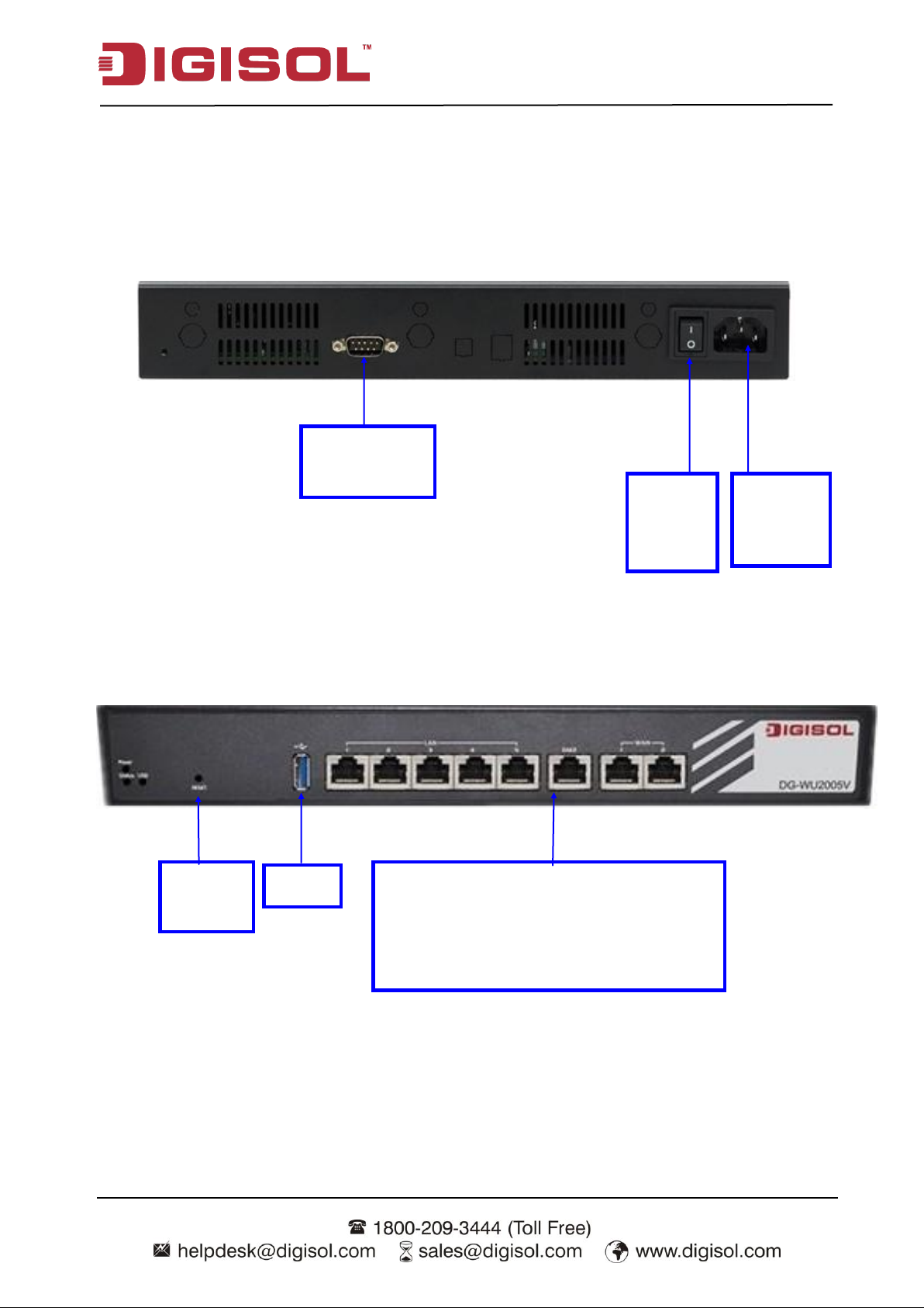
Console Port
(DB9)
Receptor
for Power
Cable
Power
ON/OFF
Switch
Auto MDI/MDIX RJ-45 Ports
2x GbE WAN to connect Internet,
1x GbE DMZ to connect local servers
5x GbE LAN to connect local devices
Reset
Button
USB
1.2.3 Hardware Configuration
Rear View:
Front View:
Page 12

12
1.2.4 LED Indicators
LED
Description
Power
OFF: Device is powered down.
Green: Device is powered on.
Status
Green in flash: Device is in normal operation.
Green in fast flash: Device is in recovery mode or abnormal state.
USB
(for 3G/4G)
OFF: USB 3G/4G connection is not established.
Green: USB 3G/4G connection is established.
Green in flash: data packet transferred via USB 3G/4G.
LAN-1 ~ LAN-5
/ DMZ
Green: Ethernet connection is established.
Green in flash: Data packet transferred via Ethernet.
OFF: No Ethernet cable attached or Device not linked.
WAN-1 / WAN-2
Green: Ethernet connection is established.
Green in flash: Data packet transferred through WAN.
OFF: No Ethernet cable attached or Device not linked.
DG-WU2005V User Manual
Page 13
DG-WU2005V User Manual
Chapter 2 Getting Started
2.1 Connect Your Device
Before you can use this product, you need to connect your PC or NB to this gateway first. You can
connect your PC to one of the LAN1~LAN5 ports through an Ethernet cable.
2.2 Easy Setup by Configuring Web UI
You can browse web UI to configure the device. Firstly you need to launch the Setup Wizard
browser first and then the Setup Wizard will guide you step-by-step to finish the basic setup
process.
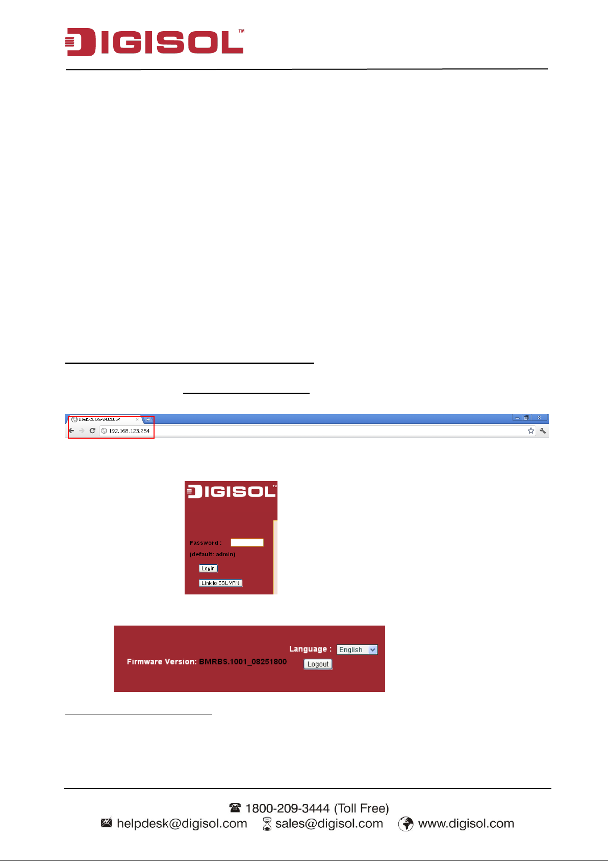
Browse to Activate the Setup Wizard
Type in the IP Address (http://192.168.123.254)1
When you see the login page, type the password „admin‟ (Refer note2) and then click „login‟
button.
After login, select your language from the list.
1 The default LAN IP address of this gateway is 192.168.123.254. If you change it, you need to
type the new IP address.
2 It‟s strongly recommending that you change this login password from default value.
13
Page 14
DG-WU2005V User Manual
2.2.1 Wizard
Select “Wizard” for basic network settings and VPN settings in a simple way. Or, you can go to
Basic Network / Advanced Network / Applications / System to setup the configuration by your
own selection.
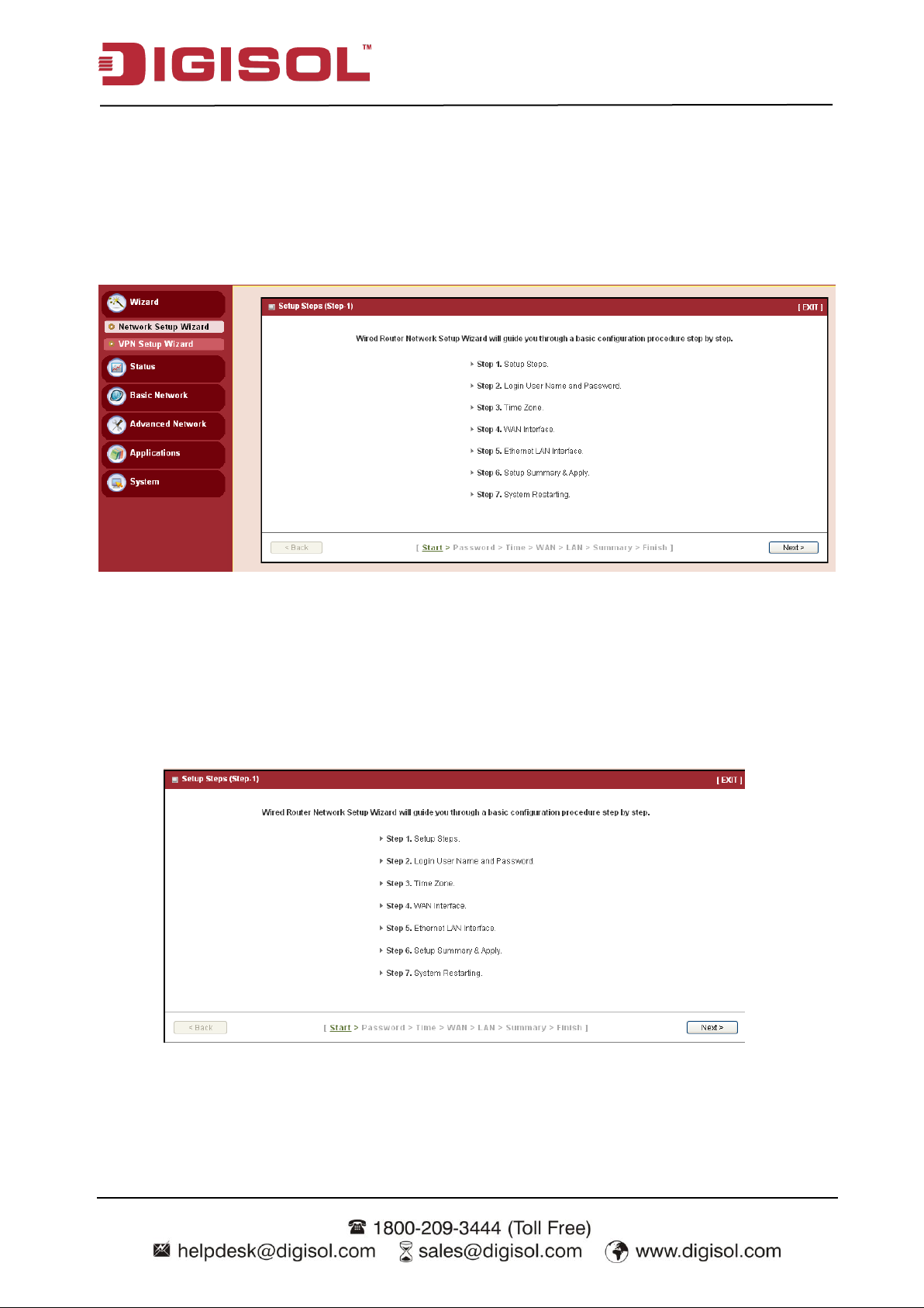
2.2.1.1 Configure with the Network Setup Wizard
Step 1
The network setup wizard will guide you to finish some basic settings, including login password,
time zone, WAN interface and LAN interface. One “Exit” button at the upper-right corner of
each window is provided for you to quit the setup process.
Press “Next” to start the wizard.
14
Page 15
DG-WU2005V User Manual
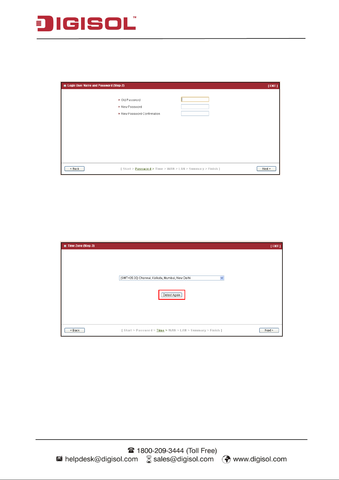
Step 2: Change Password
Password setting. You can change the login password of web UI here. It‟s strongly recommended
that you change this login password from default value.
Press “Next” to continue.
Step 3: Time Zone
Time Zone setting. It will detect your time zone automatically. If the result of auto detection is
not correct, you can press “Detect Again” button or select manually.
Press “Next” to continue.
15
Page 16
DG-WU2005V User Manual
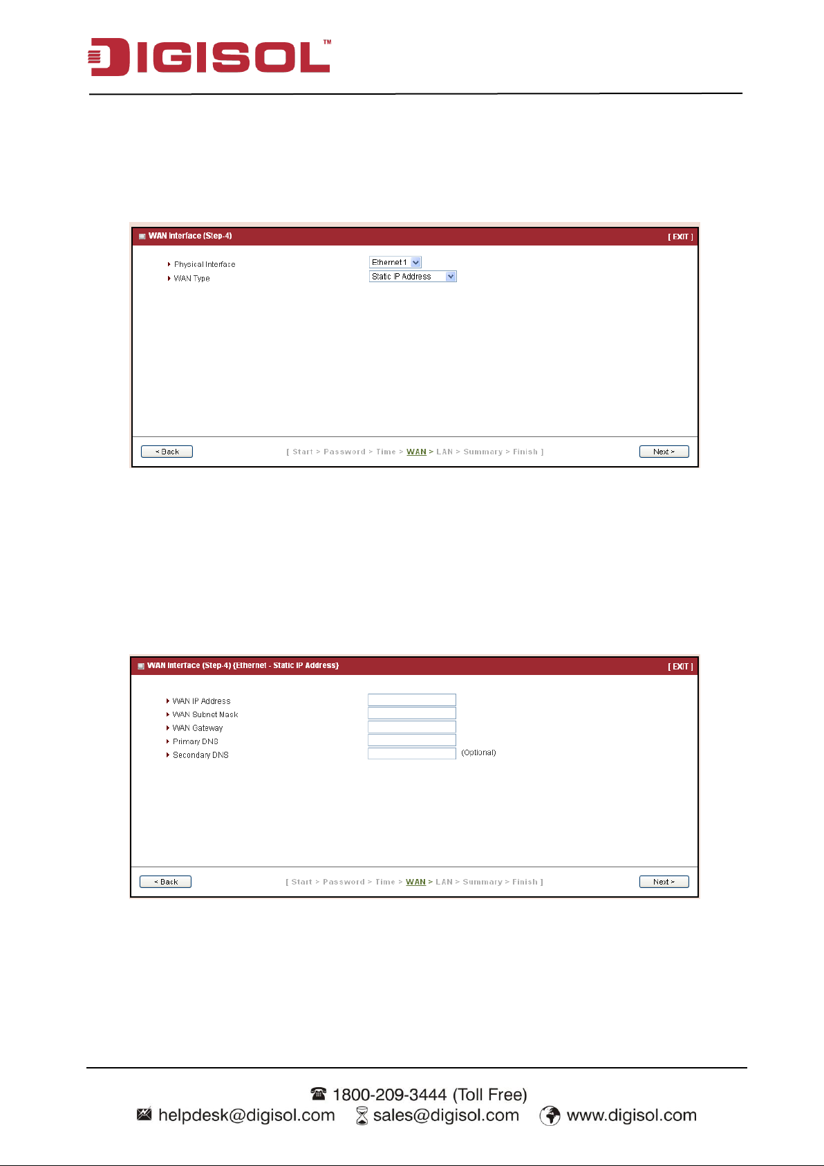
Step 4: WAN
WAN Interface setting. Choose the type of WAN connection. You can select Ethernet WAN if
you want to connect to Internet through fixed line. Or select USB 3G/4G if you want to connect
to Internet through 3G/4G network. A variety of WAN types are available for Ethernet WAN
connection.
Press “Next” to continue.
Step 4-1: Ethernet (Static IP Address)
If you choose Ethernet->Static IP Address, you need to input all IP address that you get from
ISP (Internet Service Provider) manually. This Static IP WAN Type option is usually chosen
when you get a fixed IP address from ISP.
Press “Next” to continue.
16
Page 17
DG-WU2005V User Manual
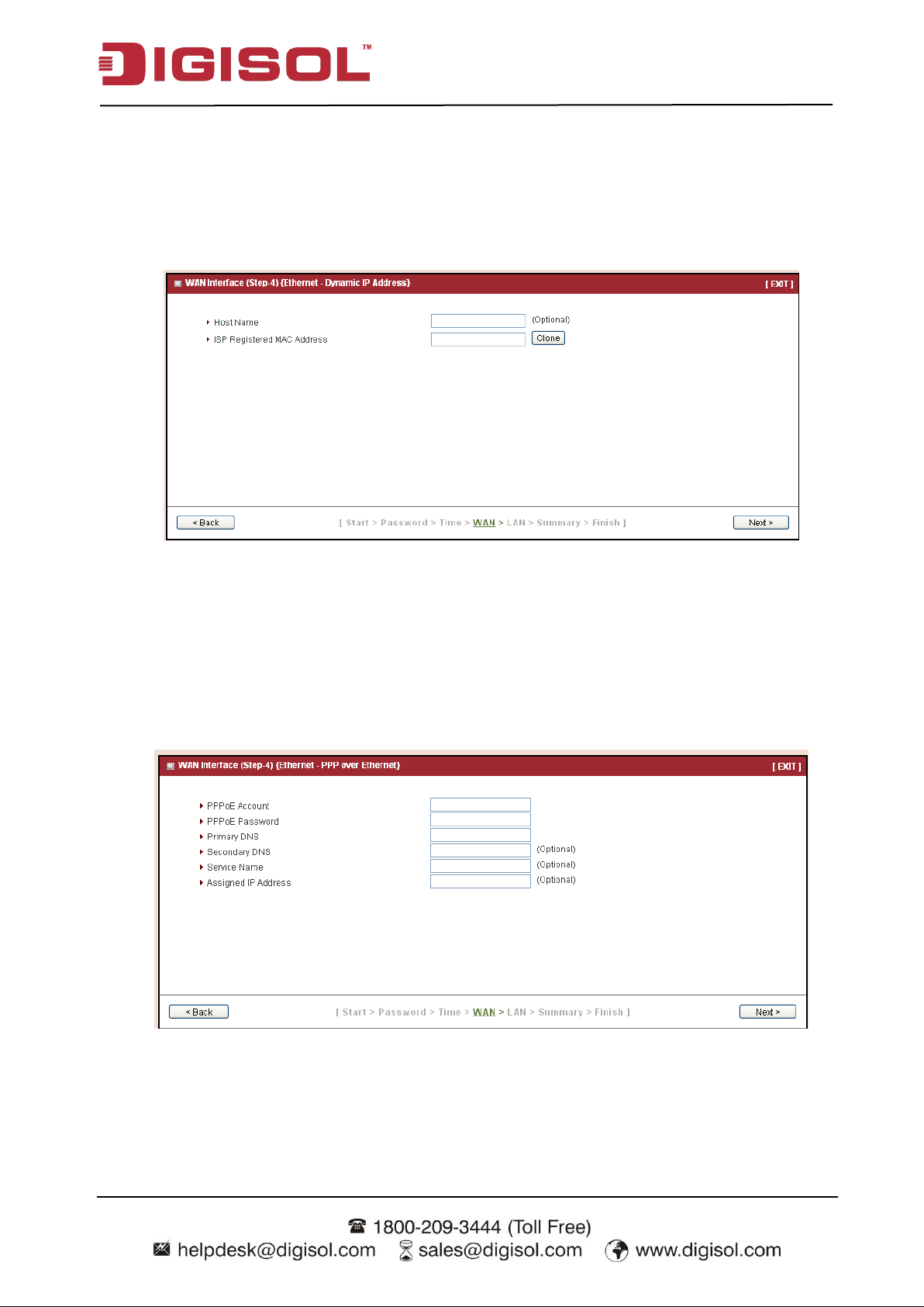
Step 4-2: Ethernet (Dynamic IP Address)
If you choose Ethernet->Dynamic IP Address, you can input host name or registered MAC
address when your ISP requests it. In most cases, you can leave them as blank and go to next.
This Dynamic IP WAN Type option is usually chosen when you get a dynamic IP address from
ISP.
Press “Next” to continue.
Step 4-3: Ethernet (PPPoE)
If you choose Ethernet->PPP over Ethernet (so-called PPPoE), you need to input account and
password that you get from ISP. For other fields, you can leave them as blank in most cases. This
PPPoE WAN Type option is usually chosen when you use ADSL for WAN connection.
Press “Next” to continue.
17
Page 18
DG-WU2005V User Manual
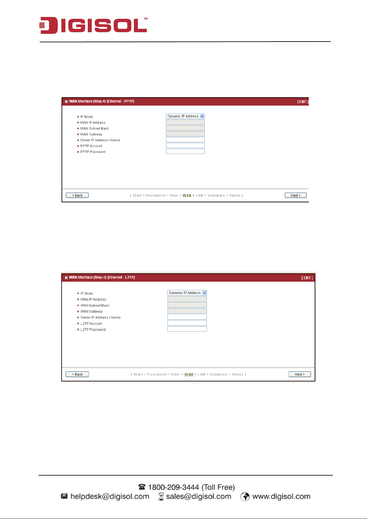
Step 4-4: Ethernet (PPTP)
If you choose Ethernet->PPTP, you need to input required dial-up information that you get
from ISP. This PPTP WAN Type option is usually chosen when your ISP requests it.
Press “Next” to continue.
Step 4-5: Ethernet (L2TP)
If you choose Ethernet->L2TP, you need to input required dial-up information that you get
from ISP. This L2TP WAN Type option is usually chosen when your ISP requests it.
Press “Next” to continue.
18
Page 19
DG-WU2005V User Manual
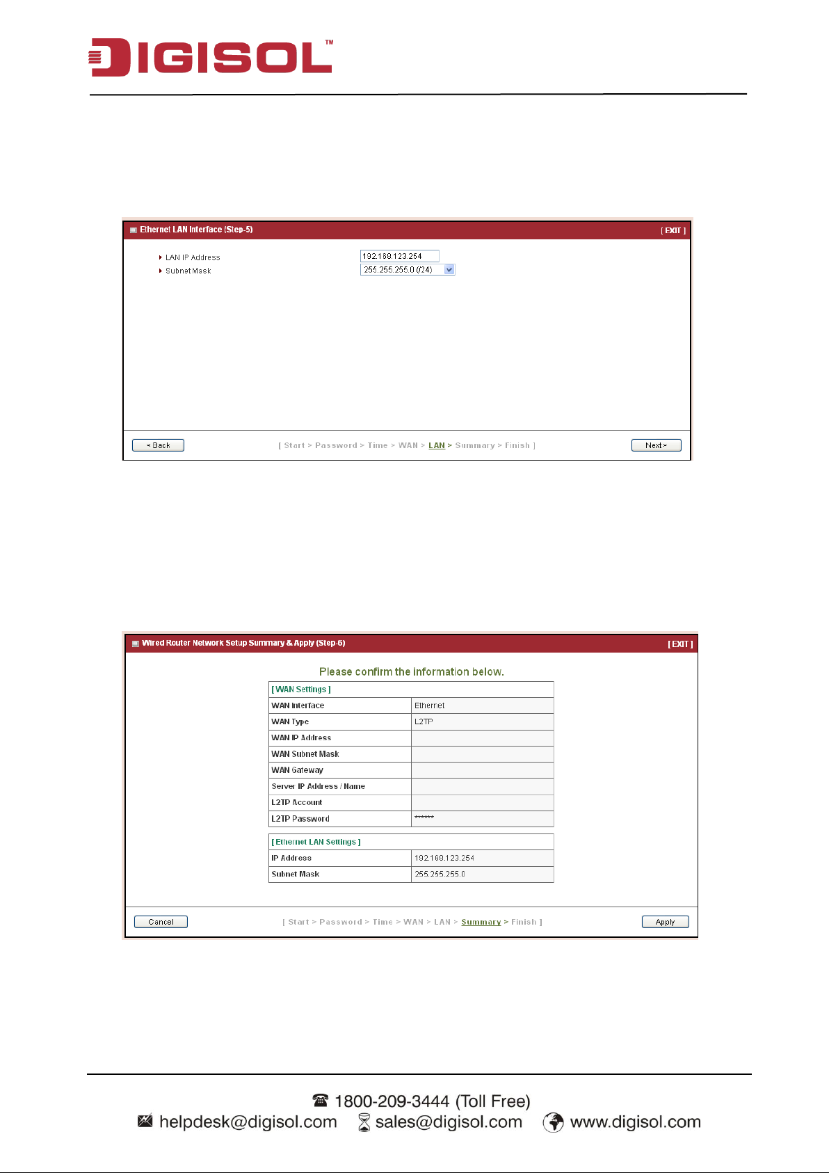
Step 5: LAN
LAN Interface setting. Change the LAN IP address and subnet mask of this gateway. You can
keep the default setting and go to next step.
Press “Next” to continue.
Step 6: Confirm and Apply
Check the new settings again. If all information is correct, please press “Apply” button to save
new settings. Then it will take 95 seconds to restart this gateway and make new settings
effective.
19
Page 20
DG-WU2005V User Manual
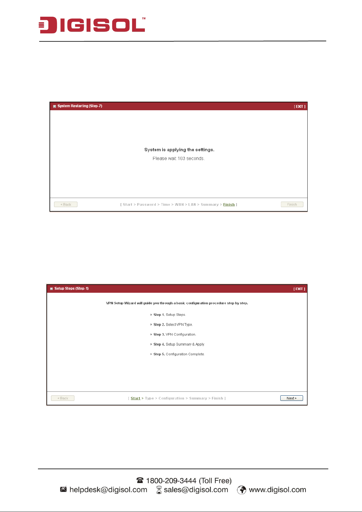
Step 7: Counting Down
Configuration is completed. Press “Finish” button to close Setup Wizard and browser counts
down for 65 seconds and provides you with “Click here” button to reconnect to the device.
2.2.1.2 Configure with the VPN Setup Wizard
Step 1
The VPN setup wizard will guide you to finish profiles of IPSec, PPTP and L2TP VPN
connection quickly.
Press “Next” to start the wizard.
20
Page 21
DG-WU2005V User Manual
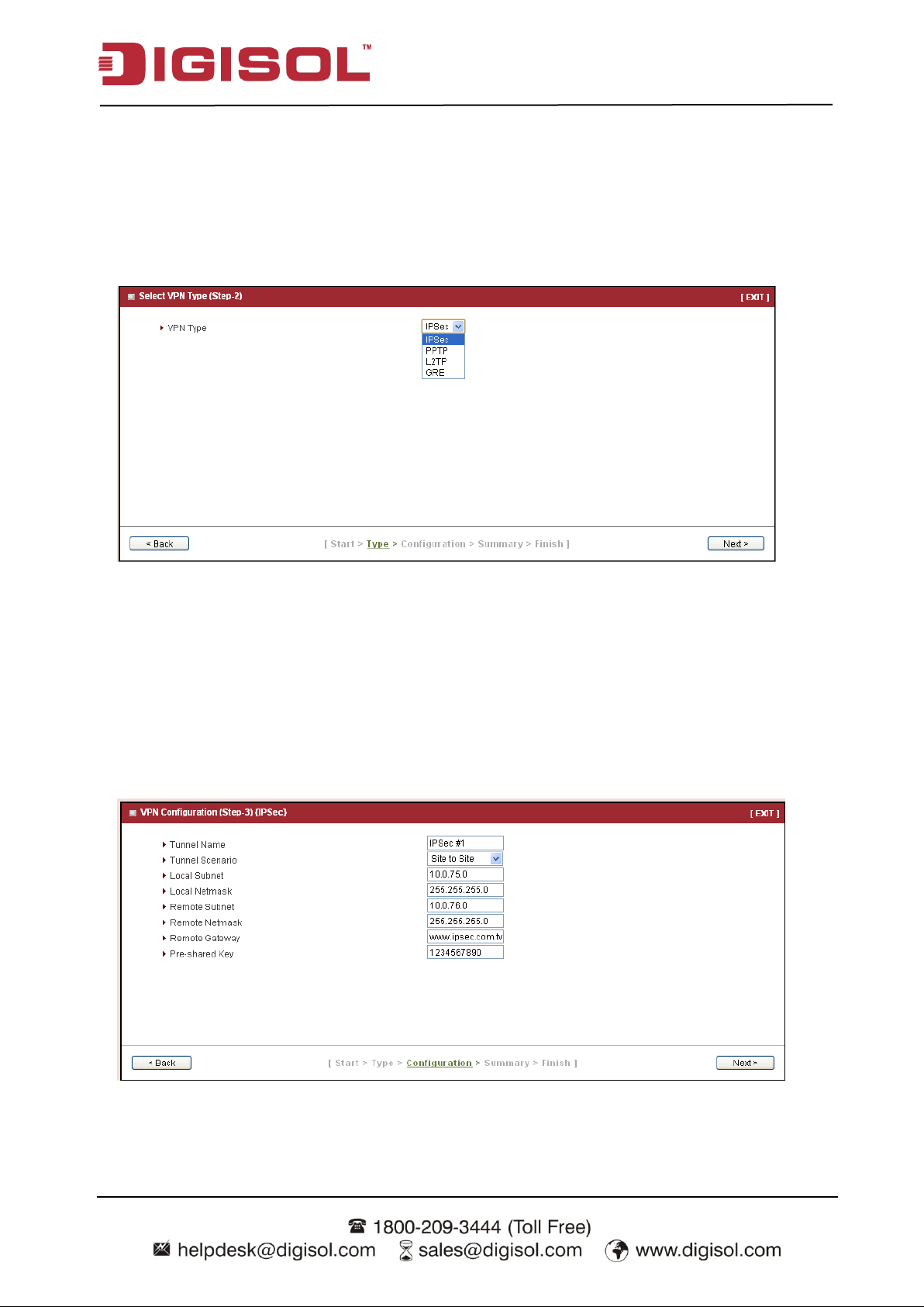
Step 2: VPN Type
Select type of VPN connection you want to create. Here you can choose IPSec, PPTP, L2TP or
GRE.
Press “Next” to continue.
Step 2-1: IPSec
If you choose IPSec, there are five options of tunnel scenario which can be chosen. “Site to
Site” is for two offices to create a VPN tunnel. “Site to Host” is for one office to create a VPN
tunnel to the control center. “Host to Site” is for the device as the control center to create a VPN
tunnel to a branch office. “Host to Host” is for creating a peer to peer secure tunnel.
“Dynamic VPN” is for remote users to connect to the device securely. For other options, please
go to Advanced Network >> VPN to setup. Input the required network information and
21
Page 22
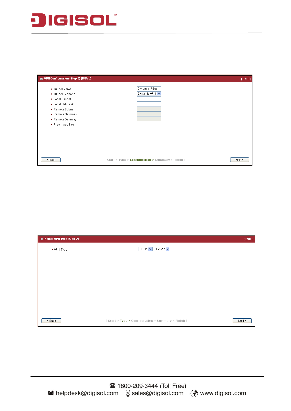
DG-WU2005V User Manual
pre-shared key for VPN connection.
For Dynamic VPN, you don‟t need to input network information o f remote subnet and remote
gateway.
Press “Next” to continue.
Step 2-2: PPTP
If you choose PPTP, there are two options of modes can be chosen. Choose “Client” if you want
this device to connect to another PPTP server. Or choose “Server” if you want other PPTP
clients to connect to it.
Press “Next” to continue.
If you choose PPTP Client, please input tunnel name, IP/FQDN of PPTP server,
username/password, authentication and MPPE options. Please make sure these settings are
22
Page 23

DG-WU2005V User Manual
accepted by PPTP server. Otherwise, remote PPTP server will reject the connection.
Press “Next” to continue.
If you choose PPTP Server, please select options of authentication and MPPE. You also need to
create a set of username and password for PPTP clients. In this wizard, you can only create one
user account. If you want to create more user accounts, please go to Advanced Network >>
VPN >> PPTP to add more users.
Press “Next” to continue.
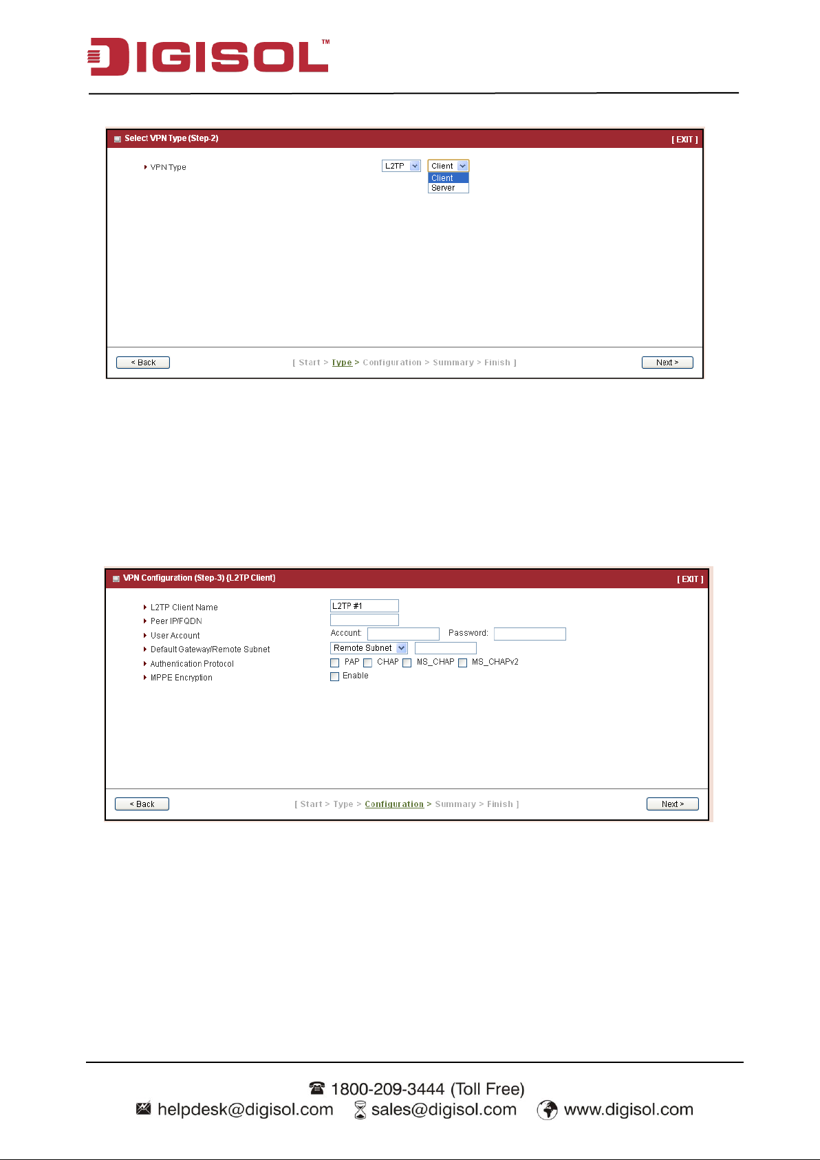
Step 2-3: L2TP
If you choose L2TP, there are two options of mode that can be chosen. Choose “Client” if you
want this device to connect to another L2TP server. Or choose “Server” if you want other L2TP
clients to connect to it.
23
Page 24
DG-WU2005V User Manual
Press “Next” to continue.
If you choose L2TP Client, please input tunnel name, IP/FQDN of L2TP server,
username/password, authentication and MPPE options. Please make sure these settings are
accepted by L2TP server. Otherwise, remote L2TP server will reject the connection.
Press “Next” to continue.
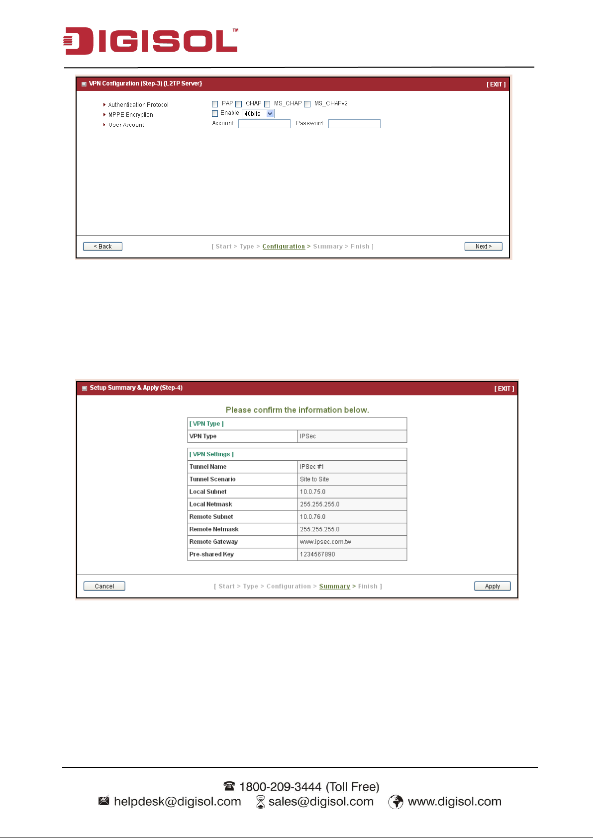
If you choose L2TP Server, please select options of authentication and MPPE. You also need to
create a set of username and password for L2TP clients. In this wizard, you can only create one
user account. If you want to create more user accounts, please go to Advanced Network >>
VPN >> L2TP to add more users.
24
Page 25
DG-WU2005V User Manual
Press “Next” to continue.
Step 3: Confirm and Apply
Confirm new settings. If all new settings are correct, please press “Apply” button to save these
new settings and make them effective.
25
Page 26
DG-WU2005V User Manual
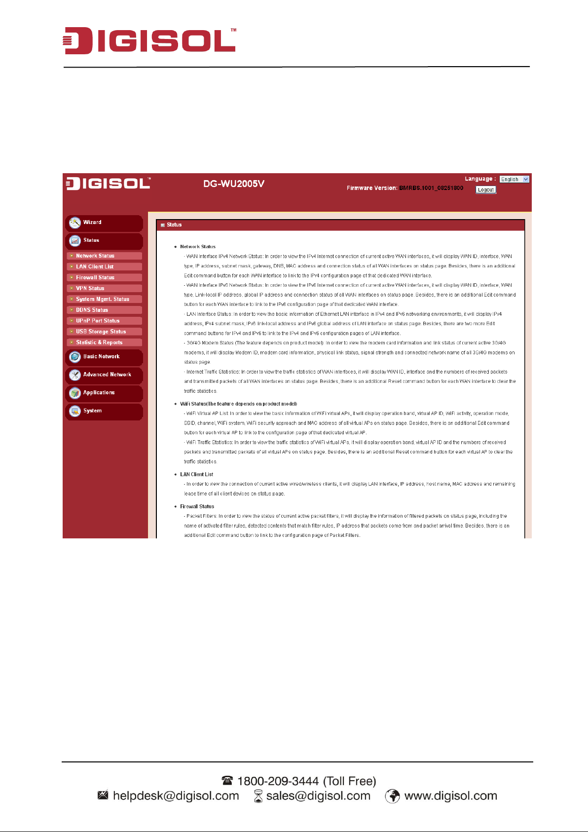
2.2.2 Status
There are 4 kinds of system status to be shown at this window. They are Network Status, LAN
Client list, Firewall Status, VPN Status and System Management Status.
26
Page 27
DG-WU2005V User Manual
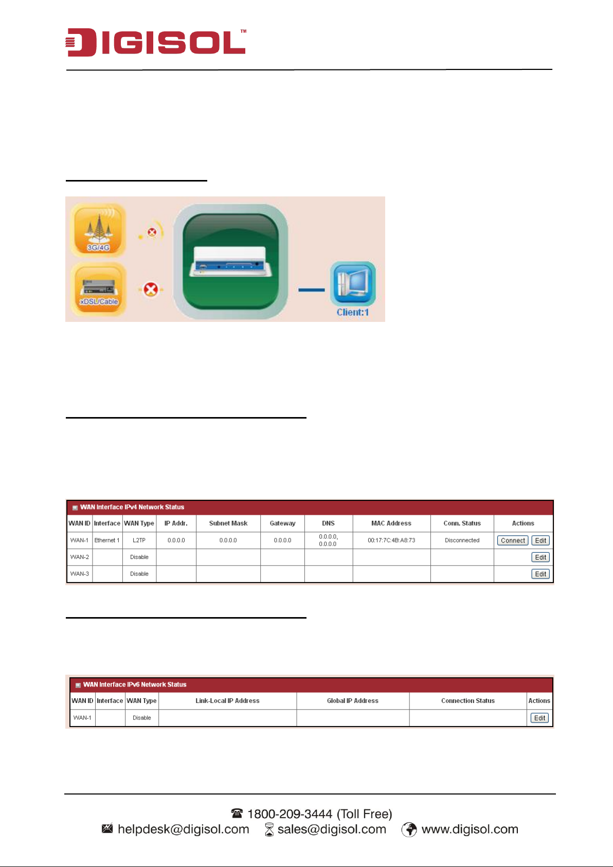
2.2.2.1 Network Status
In Network Status page, you can review lots of information of network status, including a
connection diagram, WAN IPv4 status, WAN IPv6 status, LAN status, 3G/4G modem status and
Internet Traffic Statistics. You can also check the device time at the bottom of this page.
Connection Diagram
1. 3G/4G Icon: Indicates if 3G/4G connection is established or not.
2. XDSL/Cable Icon: Indicates if Ethernet WAN connection is established or not.
3. Wired Client Icon: Indicates how many Ethernet clients are connected now.
WAN Interface IPv4 Network Status
Displays WAN type, IPv4 information, subnet mask, gateway, DNS, MAC information and
connection status of multiple WAN interfaces in IPv4 networking. Press “Edit” button if you want
to change settings.
WAN Interface IPv6 Network Status
Display WAN type, IPv6 information, and connection status of multiple WAN interfaces in IPv6
networking. Press “Edit” button if you want to change the settings.
27
Page 28
DG-WU2005V User Manual
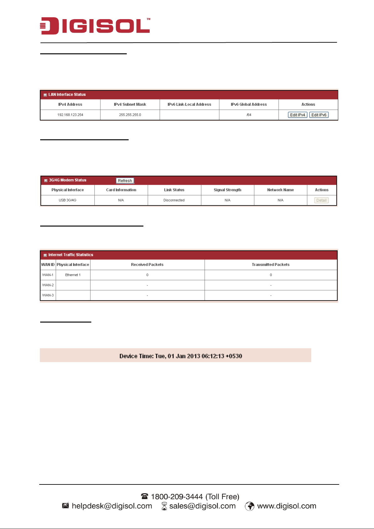
LAN Interface Status
Displays IPv4 and IPv6 information of local network. Press “Edit” button if you want to change
the settings.
3G/4G Modem Status
Displays modem card information, link status, signal strength and network (carrier) name of
3G/4G connection.
Internet Traffic Statistics
Displays number of transmitted packets and received packets of each WAN interface.
Device Time
Display current time information of device.
28
Page 29
DG-WU2005V User Manual
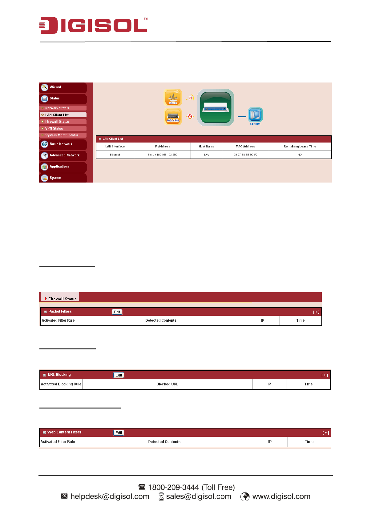
2.2.2.2 LAN Client List
Displays the LAN client information like IP address, host name, MAC address and remaining
lease time.
2.2.2.3 Firewall Status
In Firewall Status page, you can review information of filter status, including Packet Filters, URL
Blocking, Web Content Filters, MAC Control, Application Filters, IPS and other options of
firewall.
Packet Filters
Displays all detected contents of firing activated packet filter rules.
URL Blocking
Displays all blocked URLs of firing activated URL blocking rules.
Web Content Filters
Displays all detected contents of firing activated Web content filter rules.
29
Page 30
DG-WU2005V User Manual
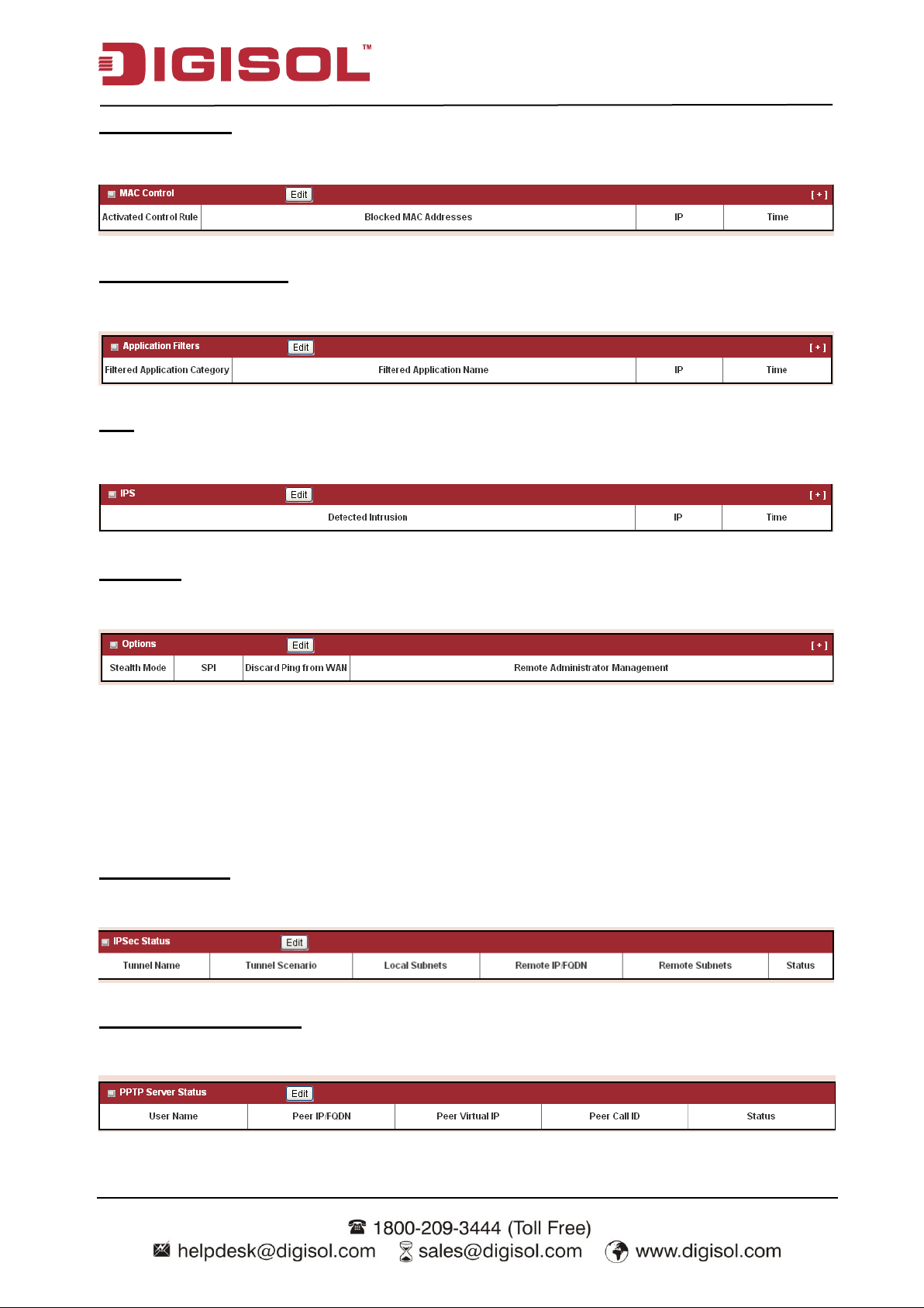
MAC Control
Displays all blocked MAC addresses of firing activated MAC control rules.
Application Filters
Displays all filtered applications of firing activated application filter rules.
IPS
Displays all events of firing activated rules of IPS.
Options
Display option settings of firewall.
2.2.2.4 VPN Status
In VPN Status page, you can review information of VPN status, including IPSec status, PPTP
Server status, PPTP Client status, L2TP Server status, L2TP Client status and SSL VPN Server
status.
IPSec Status
Displays the status of all activated tunnels of IPSec.
PPTP Server Status
Displays the status of all activated accounts of PPTP server.
30
Page 31

DG-WU2005V User Manual
PPTP Client Status
Displays the status of all activated PPTP clients.
L2TP Server Status
Displays the status of all activated accounts of L2TP server.
L2TP Client Status
Displays the status of all activated L2TP clients.
SSL VPN Server Status
Displays the status of all activated accounts of SSL VPN server.
2.2.2.5 System Management Status
In System Management Status page, you can review information of SNMP and TR-069 status.
SNMP Linking Status
Displays information of SNMP linking.
SNMP Trap Information
Displays information of SNMP traps.
31
Page 32

TR-069 Status
Displays link status of TR-069.
UPnP Status
Displays UPnP status.
2.2.2.6 DDNS Status
DG-WU2005V User Manual
In DDNS Status page, you can review information of DDNS status.
32
Page 33

DG-WU2005V User Manual
2.2.2.7 UPnP Status
In UPnP Status page, you can review information of UPnP status.
2.2.2.8 Storage Status
In Storage status page, you can review information of storage status, including device description,
usage, file system, speed and status.
33
Page 34

DG-WU2005V User Manual
2.2.2.9 Statistics and Reports
In Statistics and reports status page, you can review information of statistics and reports.
Device Manager Login Status
Displays device management status like, user name, protocol type, IP address, user level and
duration time.
Network Traffic Statistics
Displays network traffic status of the WAN, LAN, 2.4G and 5G networks.
34
Page 35

DG-WU2005V User Manual
Captive portal user login Statistics
Displays captive portal user login status, including user name, captive portal user login statistics,
create time, remaining lease time, time used, expiration time and user level.
Data usage record
Displays the data usage records.
35
Page 36

DG-WU2005V User Manual
Internet surfing list
Displays the internet surfing list including, user name, protocol, internet IMP and port, MAC,
external IMP & port and Duration time.
36
Page 37

DG-WU2005V User Manual
Chapter 3 Making Configurations
Whenever you want to configure your network or this device, you can access the Configuration
Menu by opening the web-browser and typing in the IP Address of the device. The default IP
Address is: 192.168.123.254. In the configuration section you may want to check the connection
status of the device, to do Basic or Advanced Network setup or to check the system status. These
task buttons can be easily found in the cover page of the UI (User Interface).
Enter the default password “admin” in the System Password and then click „Login‟ button.
Afterwards, you can go to Wizard, Basic Network, Advanced Network, Application or System
respectively on left hand side of web page.
37
Page 38

DG-WU2005V User Manual
38
3.1 Basic Network
You can enter Basic Network for WAN, LAN&VLAN, IPv6, NAT / Bridging, Routing, and
Client/Server/Proxy settings as the icon here shown
3.1.1 WAN Setup
This device is equipped with three WAN Interfaces to support different WAN types of connections.
You can configure one by one to get proper internet connection setup.
Ethernet WAN: The product has two RJ45 Ethernet WAN ports. Please plug in RJ45 cable from
your external DSL modem and follow UI setting to setup.
USB 3G/4G WAN: The product has one USB port for 3G/4G access, please plug in your USB
3G/4G modem dongle and follow UI setting to setup.
Page 39

DG-WU2005V User Manual
39
3.1.1.1 Physical Interface
Click on the “Edit” button for each WAN interface and you can get the detail physical
interface settings and then configure the settings as well.
By default, the WAN-1 interface is forced to “Always-on” mode, and operate as the primary
internet connection; the interface WAN-2 / WAN-3 are disabled.
1. Physical Interface: Select the WAN interface from the available list. For this device,
there are “Ethernet 1”, “Ethernet 2” and “3G/4G” items. If you would like the
Ethernet WAN1 port to operate as the primary internet connection, please choose
“Ethernet 1”.
2. Operation Mode: There are three options for this item.
Always on: Set this WAN interface to be active all the time. It means two or more
Internet connections will be established simultaneously, and outgoing data will be
transferred through these WAN connections based on load balance policies. This mode
is especially suitable for high bandwidth requirement, such as video stream transmission.
Failover: Set this WAN interface to be a backup WAN connection. This WAN interface
won‟t be active until primary WAN connection is failed. If you specified a certain WAN
interface as a “Failover” WAN, you have to further identify which WAN interface is to
Page 40

DG-WU2005V User Manual
40
be failover and fallback.
For the example above, if WAN-1 connection is broken, this gateway will try to failover
the Internet connection to this WAN interface automatically. When WAN-1 connection
becomes available again, the Internet connection will switch back to WAN-1
automatically.
Besides, for some mission-critical applications, this gateway supports “Seamless
failover”3 to shorten the switch time between WAN interface failover and failback.
That is, if an interface serves as a “Seamless Failover” WAN, the WAN connection will
be activated after the system has been booted up normally, even without data flow in it.
When the primary connection is broken, fast switching data flow to the WAN interface
is the major concern for “Seamless Failover”.
Disable: Deactivate this WAN interface.
3. Line Speed: You can specify the downstream / upstream speed (Mbps) for the
corresponding WAN connection. Such information will be referred in QoS and load
balance function to manage the traffic load for each WAN connection.
4. VLAN Tagging: If your ISP requires a VLAN tag which has been inserted into the
WAN packets, you can enable this setting, and enter the specified tag value.
Afterwards, click on “Save” to store your settings or click “Undo” to give up the changes.
3.1.1.2 Internet Setup
There are three physical WAN interfaces that you can configure one by one to get proper
internet connection setup. They include the Ethernet WANs - the DSL ISP (Dynamic IP,
Static IP, PPPoE, PPTP and L2TP connection) and the Wireless WAN - the remote wireless
ISP such as 3G/4G (LTE, HSPA+, HSPA, WCDMA, EDGE, GPRS).
3 Pl ease note your I SP will charge the connection fee even if it’s set to seamless failover.
Page 41

DG-WU2005V User Manual
41
3.1.1.2.1 Ethernet WAN
Click on the “Edit” button for the Ethernet WAN interface and you can get the detail WAN
settings and then configure the settings as well. There are 5 Internet connection types for
Ethernet physical interface. They are “Static IP”, “Dynamic IP”, “PPP over Ethernet”,
“PPTP” and “L2TP” as below.
Dynamic IP Address
1. WAN Type: Choose “Dynamic IP Address” from the drop down list.
2. Host Name: Optional, required by some ISPs, for example, @Home.
3. ISP registered MAC Address: Some ISP would ask you to register a MAC address
for Internet connection. In this case, you need to enter the registered MAC address here,
or simply press “Clone” button to copy MAC address of your PC to this field.
4. Connection Control: Select your connection control scheme from the drop down list:
“Auto-reconnect (Always on)”, “Dial-on-demand”, or “Manually”. If you select
“Auto-reconnect (Always on)”, this gateway will start to establish Internet connection
Page 42

DG-WU2005V User Manual
42
automatically since it‟s powered on. It‟s recommended to choose this scheme if for
mission critical applications to ensure Internet connection is available all the time. If you
choose “Dial-on-demand”, this gateway won‟t start to establish Internet connection until
local data is going to be sent to WAN side. After that, this gateway will disconnect WAN
connection if idle time reaches value of Maximum Idle Time. If choosing “Manually”,
this gateway won‟t start to establish WAN connection until you press “Connect” button
on web UI. After that, this gateway will disconnect WAN connection if idle time reaches
value of Maximum Idle Time. Please be noted, if the WAN interface serves as the primary
one for another WAN interface in Failover role, the Connection Control parameter will
disappear since it is “Auto-reconnect (Always on)”.
5. Maximum Idle Time: The default value is 600 seconds, you can change it if required.
The setting is required when the Connection Control is not “Auto-reconnect (Always
on)”.
6. MTU: Most ISP‟s offer MTU value to users. The default value is 0 (auto).
7. NAT: If you disable this option, it will act with a non-NAT function.
8. Network Monitoring: It is a checking mechanism design to check if the WAN
connection is alive or not. Configurable parameters include Enable/Disable,
alive-connection checking approach, Loading Checking, the interval between two checks,
the timeout of one check, response latency threshold, fail times threshold, touched target
1 and touched target 2.
9. IGMP: Enable or disable multicast traffics from the internet. You may enable as auto
mode or select by Auto, IGMP v1, IGMP v2, IGMP v3.
10. WAN IP alias: The device supports 2 WAN IP addresses for a physical interface, one is
for primary connection that provides users/devices in the LAN to access Internet; the
other is a virtual connection that lets remote user to manage this device.
Afterwards, click on “Save” to store your settings or click “Undo” to give up the changes.
Page 43

DG-WU2005V User Manual
43
Static IP Address
Select this WAN type to give your static IP information. You will need to enter in the IP
address, subnet mask and gateway address, provided to you by your ISP. Each IP address
entered in the fields must be in the appropriate IP form, which is four IP octets separated by a
dot (x.x.x.x). The Router will not accept the IP address if it is not in this format.
1. WAN Type: Choose “Static IP Address” from the drop list
2. WAN IP address / Subnet Mask / Gateway: Enter the IP address, subnet mask, and
gateway address, provided to you by your ISP.
3. Primary DNS / Secondary DNS: Input the Primary/Secondary DNS if necessary.
4. MTU: Most ISP offers MTU value to users. The default value is o (auto)
5. NAT: If you disable this option, it will act with a non-NAT function.
6. Network Monitoring: It is a checking mechanism designed to check if the WAN
connection is alive or not. Configurable parameters include Enable/Disable,
alive-connection checking approach, Loading Checking, the interval between two checks,
the timeout of one check, response latency threshold, fail times threshold, touched target
1 and touched target 2.
7. IGMP: Enable or disable multicast traffics from the internet. You may enable as auto
mode or select by Auto, IGMP v1, IGMP v2, IGMP v3.
8. WAN IP alias: The device supports 2 WAN IP addresses for a physical interface, one is
for primary connection that provides users/devices in the LAN to access Internet; the
other is a virtual connection that lets remote users to manage this device.
Page 44

DG-WU2005V User Manual
44
Afterwards, click on “Save” to store your settings or click “Undo” to give up the changes.
PPP over Ethernet
Select this WAN type if your ISP requires you to use a PPPoE connection. This option is
typically used for DSL services.
1. WAN Type: Choose “PPP Over Ethernet” from the drop list
2. IPv6 Dual Stack: You can enable this option if your ISP provides not only one IPv4 but
also one IPv6 address. Please be noted, the setting is for WAN-1 only.
3. PPPoE Account and Password: The account and password your ISP assigned to you.
Please note the account and password is case sensitive. For security concern, the
password you input won‟t be displayed on web UI.
4. Primary DNS / Secondary DNS: In most cases, ISP will assign DNS server
automatically after PPPoE connection is established. Input the IP address of primary and
secondary DNS server manually if required.
5. Connection Control: Select your connection control scheme from the drop down list:
“Auto-reconnect (Always on)”, “Dial-on-demand”, or “Manually”. If you select
“Auto-reconnect (Always on)”, this gateway will start to establish Internet connection
automatically since it‟s powered on. It‟s recommended to choose this scheme if for
mission critical applications to ensure Internet connection is available all the time. If you
Page 45

DG-WU2005V User Manual
45
choose “Dial-on-demand”, this gateway won‟t start to establish Internet connection until
local data is going to be sent to WAN side. After that, this gateway will disconnect WAN
connection if idle time reaches value of Maximum Idle Time. If you choose “Manually”,
this gateway won‟t start to establish WAN connection until you press “Connect” button
on web UI. After that, this gateway will disconnect WAN connection if idle time reaches
value of Maximum Idle Time. Please be noted, if the WAN interface serves as the primary
one for another WAN interface in Failover role, the Connection Control parameter will
disappear since it is “Auto-reconnect (Always on)”.
6. Maximum Idle Time: The default value is 600 seconds, you can change if required. The
setting is required when the Connection Control is not “Auto-reconnect (Always on)”.
7. Service Name / Assigned IP Address: ISP may ask you to use a specific service
name when connecting PPPoE connection. In some cases, ISP can also provide you a
fixed IP address with PPPoE connection. For these cases, you need to add that
information in this field.
8. MTU: Most ISP offers MTU value to users. The default MTU value is 0 (auto)
9. NAT: If you disable this option, it will act with a non-NAT function.
10. Network Monitoring: It is a checking mechanism design to check if the WAN
connection is alive or not. Configurable parameters include Enable/Disable,
alive-connection checking approach, Loading Checking, the interval between two checks,
the timeout of one check, response latency threshold, fail times threshold, touched target
1 and touched target 2.
11. IGMP: Enable or disable multicast traffics from the internet. You may enable as auto
mode or select by Auto, IGMP v1, IGMP v2, IGMP v3.
12. WAN IP alias: The device supports 2 WAN IP addresses for a physical interface, one is
for primary connection that provides users/devices in the LAN to access Internet; the
other is a virtual connection that let remote user to manage this device.
Afterwards, click on “Save” to store your settings or click “Undo” to give up the changes.
Page 46

DG-WU2005V User Manual
46
PPTP
Choose PPTP (Point-to-Point Tunneling Protocol) if your ISP used a PPTP connection.
Your ISP will provide you with a username and password. This WAN type is typically used
for DSL services.
1. WAN Type: Choose “PPTP” from the drop list.
2. IP Mode: Please check the IP mode your ISP assigned, and select “Static IP Address” or
“Dynamic IP Address” accordingly. If you select “Static IP Address” option, you have to
specify additional “WAN IP Address”, “WAN Subnet Mask” and “WAN Gateway”
settings provided by your ISP.
3. Server IP Address / Name: The IP address of the PPTP server and designated
Gateway provided by your ISP.
4. PPTP Account and Password: The account and password your ISP assigned to you.
Please note the account and password is case sensitive. For security concern, the
Page 47

DG-WU2005V User Manual
47
password you input won‟t be displayed on web UI.
5. Connection ID: Optional, input the connection ID if your ISP requires it.
6. Connection Control: Select your connection control scheme from the drop down list:
“Auto-reconnect (Always on)”, “Dial-on-demand”, or “Manually”. If you select
“Auto-reconnect (Always on)”, this gateway will start to establish Internet connection
automatically since it‟s powered on. It‟s recommended to choose this scheme if for
mission critical applications to ensure Internet connection is available all the time. If you
choose “Dial-on-demand”, this gateway won‟t start to establish Internet connection until
local data is going to be sent to WAN side. After that, this gateway will disconnect WAN
connection if idle time reaches value of Maximum Idle Time. If choosing “Manually”,
this gateway won‟t start to establish WAN connection until you press “Connect” button
on web UI. After that, this gateway will disconnect WAN connection if idle time reaches
value of Maximum Idle Time. Please be noted, if the WAN interface serves as the primary
one for another WAN interface in Failover role, the Connection Control parameter will
disappear since it is “Auto-reconnect (Always on)”.
7. Maximum Idle Time: The default value is 600 seconds, you can change if required. The
setting is required when the Connection Control is not “Auto-reconnect (Always on)”.
8. MTU: Most ISP offers MTU value to users. The default MTU value is 0 (auto)
9. MPPE (Microsoft Point-to-Point Encryption): Enable this option to add encryption on
transferred and received data packets. Please check with your ISP to see if this feature is
supported or not.
10. NAT: If you disable this option, it will act with a non-NAT function.
11. Network Monitoring: It is a checking mechanism designed to check if the WAN
connection is alive or not. Configurable parameters include Enable/Disable,
alive-connection checking approach, Loading Checking, the interval between two
checking, the timeout of one checking, response latency threshold, fail times threshold,
touched target 1 and touched target 2.
12. IGMP: Enable or disable multicast traffics from the internet. You may enable as auto
mode or select by Auto, IGMP v1, IGMP v2, IGMP v3.
13. WAN IP alias: The device supports 2 WAN IP addresses for a physical interface, one is
for primary connection that provides users/devices in the LAN to access Internet; the
other is a virtual connection that lets remote user to manage this device.
Afterwards, click on “Save” to store your settings or click “Undo” to give up the changes.
Page 48

DG-WU2005V User Manual
48
L2TP
Choose L2TP (Layer 2 Tunneling Protocol) if your ISP uses a L2TP connection. Your ISP
will provide you with a username and password. This option is typically used for DSL
services.
1. WAN Type: Choose “L2TP” from the drop down list
2. IP Mode: Please check the IP mode your ISP assigned, and select “Static IP Address” or
“Dynamic IP Address” accordingly. If you select “Static IP Address” option, you have to
specify additional “WAN IP Address”, “WAN Subnet Mask” and “WAN Gateway”
settings provided by your ISP.
3. Server IP Address / Name: The IP address of the PPTP server and designated
Gateway provided by your ISP.
4. L2TP Account and Password: The account and password your ISP assigned to you.
Please note the account and password is case sensitive. For security reasons, the password
you input won‟t be displayed on web UI.
5. Connection Control: Select your connection control scheme from the drop down list:
“Auto-reconnect (Always on)”, “Dial-on-demand”, or “Manually”. If you select
Page 49

DG-WU2005V User Manual
49
“Auto-reconnect (Always on)”, this gateway will start to establish Internet connection
automatically since it‟s powered on. It‟s recommended to choose this scheme if for
mission critical applications to ensure Internet connection is available all the time. If you
choose “Dial-on-demand”, this gateway won‟t start to establish Internet connection until
local data is going to be sent to WAN side. After that, this gateway will disconnect WAN
connection if idle time reaches value of Maximum Idle Time. If you choose “Manually”,
this gateway won‟t start to establish WAN connection until you press “Connect” button
on web UI. After that, this gateway will disconnect WAN connection if idle time reaches
value of Maximum Idle Time. Please note that, if the WAN interface serves as the
primary one for another WAN interface in Failover role, the Connection Control
parameter will disappear since it is “Auto-reconnect (Always on)”.
6. Maximum Idle Time: The default value is 600 seconds, you can change it if required.
The setting is required when the Connection Control is not “Auto-reconnect (Always
on)”.
7. MTU: Most ISP offers MTU value to users. The default MTU value is 0 (auto)
8. MPPE (Microsoft Point-to-Point Encryption): Enable this option to add encryption on
transferred and received data packets. Please check with your ISP to see if this feature is
supported or not.
9. NAT: If you disable this option, it will act with a non-NAT function.
10. Network Monitoring: It is a checking mechanism designed to check if the WAN
connection is alive or not. Configurable parameters include Enable/Disable,
alive-connection checking approach, Loading Checking, the interval between two
checking, the timeout of one checking, response latency threshold, fail times threshold,
touched target 1 and touched target 2.
11. IGMP: Enable or disable multicast traffics from the internet. You may enable as auto
mode or select by Auto, IGMP v1, IGMP v2, IGMP v3.
12. WAN IP alias: The device supports 2 WAN IP addresses for a physical interface, one is
for primary connection that provides users/devices in the LAN to access Internet; the
other is a virtual connection that lets remote user to manage this device.
Afterwards, click on “Save” to store your settings or click “Undo” to give up the changes.
Page 50

DG-WU2005V User Manual
50
3.1.1.2.2 Wireless WAN – 3G/4G
Click on the “Edit” button for the 3G/4G WAN interface and you can get the detail WAN
settings and then configure the settings as well.
1. WAN Type: Choose “3G” from the drop list.
2. Dial-up Profile: After you subscribe 3G/4G data service, your operator will provide
some information for you to setup connection, such as APN, dialed number, account, or
password. If you know this information exactly, you can choose “Manual-configuration”
setting and type in that information by your own. Otherwise, you can select
“Auto-detection” to let this gateway detect automatically. Even you choose
“Manual-configuration” setting, this gateway will show responding information for your
reference after you select country and service provider.
3. APN / PIN Code: Enter the PIN Code for your SIM card (Optional).
Page 51

DG-WU2005V User Manual
51
4. Dialed Number: Enter the dialed number that is provided by your ISP.
5. Account, Password: Enter the account / Password that is provided by your ISP
(Optional).
6. Authentication: Choose “Auto”, “PAP”, or “CHAP” according to your ISP‟s
authentication approach.
7. Primary / Secondary DNS: Enter IP address of Domain Name Server (Optional). You
can keep them in blank, because most ISP will assign them automatically.
8. Maximum Idle Time: The default value is 600 seconds, you can change if required. The
setting is required when the Connection Control is not “Auto-reconnect (Always on)”.
9. Time Schedule: This option allows you to limit WAN connection available in a certain
time period. You can select “Always” available or “By Schedule” for connection method.
If you choose “By Schedule” rule, you need to add a new schedule at System >>
Scheduling menu.
10. MTU: MTU refers to Maximum Transmit Unit. Different WAN types of connection will
have different value. You can leave it with 0 (Auto) if you are not sure about this setting.
11. NAT: If you disable this option, it will act with a non-NAT function.
12. Network Monitoring: It is a checking mechanism design to check if the WAN
connection is alive or not. Configurable parameters include Enable/Disable,
alive-connection checking approach, Loading Checking, the interval between two
checking, the timeout of one checking, response latency threshold, fail times threshold,
touched target 1 and touched target 2.
13. IGMP: Enable or disable multicast traffics from the internet. You may enable as auto
mode or select by Auto, IGMP v1, IGMP v2, IGMP v3.
Afterwards, click on “Save” to store your settings or click “Undo” to give up the changes.
3.1.1.3 Load Balance
This device supports multi-WAN load balance function and more than one WAN interface
can access Internet at the same time. The load balance function can help you to manage the
outbound traffics and to maximize the utilization of available bandwidth.
1. Load Balance: Enable or disable the load balance function.
2. Load Balance Strategy: Once you enabled the load balance function, you have to
Page 52

DG-WU2005V User Manual
52
further configure which strategy is to be applied for load balancing the outbound traffics.
There are three load balance strategy: “By Smart Weight”, “By Priority” and “By User
Policy”.
By Smart Weight:
If you choose the “By Smart Weight” strategy, no other setting is required. This device will
automatically allocate the outbound traffics to each WAN interface.
By Priority:
1. Priority: If you choose the “By Priority” strategy, you have to further specify the
outbound traffic percentage for each WAN interface. The load balancing mechanism will
follow these settings to allocate proper traffics for each WAN to access the internet.
By User Policy:
If you choose the “By User Policy” strategy, you have to further create the expected policies
Page 53

DG-WU2005V User Manual
53
one by one. Click the “add” button to add your load balance policy.
You can manage the outbound traffics flow and the force specific traffics to access Internet
through designated WAN interface. For those traffics not covered in the user policy rules, the
device will allocate the WAN interface by applying “Smart Weight” mechanism
simultaneously.
1. Source IP Address: Enter the expected Source IP Address for the load balance policy.
It can be “Any”, “Subnet”, “IP Range”, or “Single IP”. Just choose one type of the source
IP address, and specify its value as well. If you don‟t want to specify a certain source IP
address for this policy, just leave it as “Any”
2. Destination IP Address, Destination Port: Enter the expected Destination IP
Address and / or the Port number for the load balance policy. It can be “Any”, “Subnet”,
“IP Range”, “Single IP”, or “Domain Name”. Just choose one type of the destination IP
address, and specify its value as well. If you don‟t want to specify a certain destination IP
address for this policy, just leave it as “Any”
3. Destination Port: Enter the expected Destination Port number for the load balance
policy. It can be “All”, “Port Range”, “Single Port”, or “Well-known Applications”. Just
choose one type of the destination port, and specify its value as well. If you don‟t want to
specify a certain destination port for this policy, just leave it as “All”
4. Protocol: Enter the expected protocol type for the load balance policy. It can be “TCP”,
“UDP”, or “Both”. If you don‟t want to specify a certain protocol type for this policy, just
leave it as “Both”
5. WAN Interface: Identify which WAN interface is to be selected for accessing the
Internet if all of above source and destination criteria are matched for the outbound
traffics.
6. Policy: Enable or disable this user policy.
Page 54

DG-WU2005V User Manual
54
3.1.2 LAN & VLAN
This device is equipped with five gigabit Ethernet LAN ports as to connect your local devices
via Ethernet cables. Besides, VLAN function is provided to organize your local networks.
3.1.2.1 Ethernet LAN
Please follow the below mentioned instructions for an IPv4 Network Setup.
1. LAN IP Address: The local IP address of this device. The computer on your network
must use the LAN IP address of this device as their Default Gateway. You can change it if
necessary. It‟s also the IP address of web UI. If you change it, you need to type new IP
address in the browser to see web UI.
2. Subnet Mask: Select your subnet mask. Subnet mask defines how many clients are
allowed in one network or subnet. The default subnet mask is 255.255.255.0, and it
means maximum 254 IP addresses are allowed in this subnet. However, one of them is
occupied by LAN IP address of this gateway, so there are maximum 253 clients allowed
in LAN network. Hereafter are the available options for subnet mask.
Page 55

DG-WU2005V User Manual
55
Afterwards, click on “Save” to store your settings or click “Undo” to give up the changes.
3.1.2.2 VLAN
This section provides a brief description of VLANs and explains how to create and modify
virtual LANs which are more commonly known as VLANs. A VLAN is a logical network
under a certain switch or router device to group lots of client hosts with a specific VLAN ID.
This device supports both Port-based VLAN and Tag-based VLAN. In Port-based VLAN, all
client hosts belong to the same group by transferring data via some physical ports that are
tagged with same VLAN ID in the device. The ports of a VLAN form an independent traffic
domain in which the traffic generated by the nodes remain within the VLAN. However, in
Tag-based VLAN, all packets with the same VLAN ID will be treated as the same group of
and own same access property and QoS property. It is especially useful when individuals of a
VLAN group are present at different locations.
The VLAN function allows you to divide local network into different “virtual LANs”. In
some cases, ISP may need router to support “VLAN tag” for certain kinds of services (e.g.
IPTV) to work properly. In some cases, SMB departments are separated and located at any
floor of building. All client hosts in same department should own common access property
and QoS property. You can select either one operation mode, port-based VLAN or tag-based
VLAN, and then configure according to your network configuration.
Page 56

DG-WU2005V User Manual
56
3.1.2.2.1 VLAN Scenarios
There are some common VLAN scenarios as follows:
Port-Based VLAN Tagging for Differentiated Services
Port-based VLAN function can group Ethernet ports, Port-1 ~ Port-5, together for
differentiated services like Internet surfing, multimedia enjoyment, VoIP talking and so on.
Two operation modes, NAT and Bridge, can be applied to each VLAN group. One DHCP
server is allocated for a NAT VLAN group to let group host member get its IP address. Thus,
such a host can surf Internet via the NAT mechanism of business access gateway. But at
bridge mode, Intranet packet flow was delivered out WAN trunk port with VLAN tag to
upper link for different services.
Page 57

DG-WU2005V User Manual
57
A port-based VLAN is a group of ports on an Ethernet or Virtual APs of Wired or Wireless
Gateway that form a logical group segment. Following is a descriptive example, and there is
difference at interfaces for different models. In SMB or a company, administrator schemes out 4
segments, Lobby, Lab & Servers, Office and VoIP & IPTV. In a Wireless Gateway (there is no
Wi-Fi interface for some models), administrator can configure Lobby segment with VLAN ID 4.
The VLAN group includes Port-4 and VAP-8 (SSID: Guest) with NAT mode and DHCP-3 server
equipped. He also configures Lab & Servers segment with VLAN ID 3. The VLAN group
includes Port-3 with NAT mode and DHCP-2 server equipped. However, he configures Office
segment with VLAN ID 2. The VLAN group includes Port-2 and VAP-1 (SSID: Staff) with NAT
mode and DHCP-1 server equipped. At last, administrator also configures VoIP & IPTV segment
with VLAN ID 11. The VLAN group includes Port-1 with bridge mode to WAN interface as
shown at following diagram.
Page 58

DG-WU2005V User Manual
58
Tag-based VLAN Tagging for Location-free Departments
Tag-based VLAN function can group Ethernet ports, Port-1 ~ Port-5 , together with different
VLAN tags for deploying department subnets in Intranet. All packet flows can carry with different
VLAN tags even at the same physical port for Intranet. These flows can be directed to different
destination because they have differentiated tags. The approach is very useful to group some hosts
in different geographic location to be the same department.
Tag-based VLAN is also called a VLAN Trunk. The VLAN Trunk collects all packet flows
with different VLAN IDs from Router device and delivers them in the Intranet. VLAN
membership in a tagged VLAN is determined by VLAN ID information within the packet
frames that are received on a port. Administrator can further use a VLAN switch to separate
the VLAN trunk to different groups based on VLAN ID. Following is an example. In SMB or
a company, administrator schemes out 3 segments, Lobby & Restaurant, Lab & Meeting
Rooms and Office. In a Security VPN Gateway, administrator can configure Lobby &
Restaurant segment with VLAN ID 12. The VLAN group is equipped with DHCP-3 server to
construct a 192.168.12.x subnet. He also configures Lab & Meeting Rooms segment with
VLAN ID 11. The VLAN group is equipped with DHCP-2 server to construct a 192.168.11.x
subnet for Intranet only. That is, any client host in VLAN 11 group can‟t access the Internet.
However, he configures Office segment with VLAN ID 10. The VLAN group is equipped
with DHCP-1 server to construct a 192.168.10.x subnet. In this example, VLAN 10 and 12
groups can access the Internet as shown in the following diagram.
Page 59

DG-WU2005V User Manual
59
VLAN Group Access Control
Administrator can specify the Internet access right for all VLAN groups. He also can
configure which VLAN groups can communicate with each other.
VLAN Group Internet Access
Administrator can specify members of one VLAN group to be able to access Internet or not.
Following is an example that VLAN groups of VID is 1 and 4 can access Internet but the one
with VID is 3 can‟t. That is, visitors in Lobby and staff in office can access Internet. But ones
in Lab can‟t because of security issue. Servers in Lab serve only for trusted staffs or are
accessed in secure tunnels.
Page 60

DG-WU2005V User Manual
60
Inter VLAN Group Routing
In Port-based tagging, administrator can specify member hosts of one VLAN group to be able
to communicate with the ones of another VLAN group or not. This is a communication pair,
and one VLAN group can join many communication pairs. But communication pair has not
the transitive property. That is, A can communicate with B, and B can communicate with C,
that does not mean A can communicate with C. An example is shown in the following
diagram. VLAN groups of VID is 1 and 3 can access each other but the ones between VID 3
and VID 4 and between VID 1 and VID 4 cannot.
Page 61

DG-WU2005V User Manual
61
3.1.2.2.2 Port-Based VLAN
A port-based VLAN is a group of ports on an Ethernet switch or router that forms a logical
group segment. There are five LAN ports in this device, so you can have various VLAN
configurations to organize the available LAN ports if required.
At first, you must select the “Port-based” for your VLAN configuration type if you want to.
Based on your selection of VLAN Type, you can do corresponding configuration.
Besides, the device provides a DMZ port for various servers deployment in the Intranet. For
its VLAN configuration, you must specify which DHCP server needs to be used for the DMZ
port by clicking on the “Edit” button. Please be noted that the virtual server, virtual computer
and DMZ host configuration in Basic Network >> NAT/Bridging needs to be same subnet
with the specific DHCP server for DMZ Port.
Now, you can setup the VLAN configuration for all Ethernet LAN ports in the device. By
default, all the 5 LAN ports belong to one VLAN. This VLAN is a NAT type network, and
the IP address of all local devices is allocated by DHCP-1 server. If you want to divide them
Page 62

DG-WU2005V User Manual
62
into different VLANs, click on the “Edit” button related to each port.
1. NAT/Bridge: Select “NAT” or “Bridge” to identify if the packets are directly bridged to
the WAN port or processed by NAT mechanism.
2. VLAN ID: Specify a VLAN identifier for this port. The ports with the same VID are in
the same VLAN group. When NAT/Bridge is “Bridge” and the “Tx Tag” is checked, the
VLAN ID will be equal to the WAN ID and will carry that VID into the VLAN group of
subnet.
3. Tx TAG: If NAT/Bridge is “Bridge”, the specific Ethernet LAN port will bridge to some
WAN interface and carry the VLAN ID into the VLAN group of subnet by checking the
Tx TAG box.
4. DHCP Server: Specify a DHCP server for configuring VLAN. This device provides up
to 6 DHCP servers to serve the DHCP requests from different VLANs and DMZ port.
You must define the DHCP Server objects beforehand in Basic Network >>
Client&Server&Proxy to assign one DHCP Server object to one VLAN group that is
NAT type.
5. Available WAN: If “NAT/Bridge” is “Bridge”, you must specify which WAN interface
will be the target interface to bridge from the Ethernet LAN port.
6. WAN VID: The VLAN Tag ID that comes from the ISP service. For NAT type VLAN, no
WAN VLAN tag is allowed and the value is forced to “0”. For Bridge type VLAN, You
have to specify the VLAN Tag value that is provided by your ISP.
Page 63

63
7. VLAN Routing Group:
DG-WU2005V User Manual
Above configuration example supports 3 access policies. The first one is Internet Access
Policy that includes Port-1, Port-2 and Port-3. All client hosts via these ports can access
the Internet. The second policy is Intranet access Policy that includes only Port-4. All
client hosts via the port can‟t access the Internet. But the Ethernet client hosts of VLAN 1
and 3 groups can communicate with each other. The last one policy is the Bridge to WAN
Policy that includes only Port-5.
Afterwards, click on “Save” to store your settings or click “Undo” to give up the changes.
3.1.2.2.3 Tag-Based VLAN
The second type of VLAN is the tag-based VLAN. VLAN membership in a tagged VLAN is
determined by information within the frames that are received on a port. This differs from a
port-based VLAN, where the port VIDs assigned to the ports determine VLAN membership.
When the device receives a frame with a VLAN tag, referred to as a tagged frame, the device
forwards the frame only to those ports that share the same VID.
Page 64

DG-WU2005V User Manual
64
Besides DMZ Port, all the LAN ports belong to one VLAN group, and this VLAN ID is
forced to “1”. It is a special tag based VLAN for devices to operate, there is no tag required
for this default VLAN ID.
If you want to configure your own tag-based VLANs, select “Tag-based” for VLAN Type
first.
Besides, the device provides a DMZ port for various servers deployment in the Intranet. For
its VLAN configuration, you must specify which DHCP server to be used for the DMZ port
by clicking on the “Edit” button. You also can define the VLAN ID there. Please be noted
that the virtual server, virtual computer and DMZ host configuration in Basic Network >>
NAT/Bridging need to be same subnet with the specific DHCP server for DMZ Port.
Now, you can setup the VLAN configuration for some different VLAN groups that you need.
From the Tag-based VLAN List, you can add one new VLAN group by clicking on the
Page 65

DG-WU2005V User Manual
65
“Add” command button. But also you can modify some existing VLAN groups by clicking
corresponding “Edit” command buttons at the end of each VLAN group in the Tag-based
VLAN List. Besides, unnecessary VLAN groups can be removed by checking the “Select”
box for those groups and then clicking on the “Delete” command button at the Tag-based
VLAN List caption
1. VLAN ID: Specify a VLAN tag for this VLAN group. The packets with the same VID are
in the same VLAN group.
2. Internet: Specify whether this VLAN can access Internet or not. If it is checked, all the
packets will be un-tagged before it is forwarded to Internet, and all the packets from
Internet will be tagged with the VLAN ID before it is forwarded to the destination
belonging to this configured VLAN group.
3. Port 1 ~ Port 5: Specifies whether it belongs to the VLAN group or not. You just have
to select the check box of the selected ports.
4. DHCP Server1~6 and “---“: Specify a DHCP server for configuring the VLAN. This
device provides up to 6 DHCP servers to serve the DHCP requests from different VLANs.
If you choose” ---”, it means Gateway will not make any response for those DHCP
requests with that VLAN ID.
Afterwards, click on “Save” to store your settings or click “Undo” to give up the changes.
Page 66

DG-WU2005V User Manual
66
3.1.3 IPv6 Setup
The growth of the Internet has created a need for more addresses than those that are possible with
IPv4. IPv6 (Internet Protocol version 6) is a version of the Internet Protocol (IP) intended to
succeed IPv4, which is the protocol currently used to direct almost all Internet traffic. IPv6 also
implements additional features not present in IPv4. It simplifies aspects of address assignment
(stateless address auto-configuration), network renumbering and router announcements when
changing Internet connectivity providers. This router supports various types of IPv6 connection
(IPv6 6 to 4 / IPv6 in IPv4 tunnel).
Please ask your ISP what type of IPv6 is supported before you proceed with IPv6
setup.
3.1.3.1 6 to 4
When “6 to 4” IPv6 is selected you need to do the following settings:
6 to 4 WAN IPv6 address settings:
1. 6 to 4 Settings: You may obtain IPv6 DNS automatically or set DNS address manually
for Primary DNS address and secondary DNS address.
2. DNS: Please enter the IPv6 address Primary DNS address and secondary DNS address.
3. MLD Snooping: MLD snooping, IPv6 multicast data is selectively forwarded to a list of
ports that want to receive the data, instead of being flooded to all ports in a VLAN. This
Page 67

DG-WU2005V User Manual
67
list is constructed by snooping IPv6 multicast control packets. If necessary in your
environment, please enable this feature.
LAN Configuration:
4. Global Address: Please enter global Address.
5. LAN IPv6 address settings: Please enter “LAN IPv6 address” and ignore the “LAN
IPv6 Link-Local address”.
Address auto configuration settings:
6. Auto-configuration: Disable or enable this auto configuration setting.
7. Auto-configuration type: You may set stateless or stateful (Dynamic IPv6).
8. Router advertisement Lifetime: You can set the time for the period that the router
send (broadcast) its router advertisement. Each router periodically multicasts a Router
Advertisement from each of its multicast interfaces, announcing the IP address (es) of that
interface. Hosts discover the addresses of their neighboring routers simply by listening
for advertisements. When a host attached to a multicast link starts up, it may multicast a
Router Solicitation to ask for immediate advertisements, rather than waiting for the next
periodic ones to arrive; if and only if no advertisements are forthcoming, the host may
retransmit the solicitation a small number of times, but then must desist from sending any
more solicitations. Any routers that subsequently start up, or that were not discovered
because of packet loss or temporary link partitioning, are eventually discovered by
reception of their periodic (unsolicited) advertisements.
3.1.3.2 6 in 4
Page 68

DG-WU2005V User Manual
68
When “6 in 4” is selected you need to do the following settings:
6 in 4 WAN IPv6 address settings:
1. Remote / Local IPv4 and IPv6 Address: You may add remote / local IPv4 address
and local IPv6 address, then set DNS address manually for Primary DNS address and
secondary DNS address.
2. DNS: Please enter IPv6 address Primary DNS address and secondary DNS address.
3. MLD Snooping: MLD snooping, IPv6 multicast data is selectively forwarded to a list of
ports that want to receive the data, instead of being flooded to all ports in a VLAN. This
list is constructed by snooping IPv6 multicast control packets. If necessary in your
environment, please enable this feature.
LAN Configuration:
4. Global Address: Please enter global Address.
5. LAN IPv6 address settings: Please enter “LAN IPv6 address” and ignore the “LAN
IPv6 Link-Local address”.
Address auto configuration settings:
6. Auto-configuration: Disable or enable this auto configuration setting.
7. Auto-configuration type: You may set stateless or stateful (Dynamic IPv6).
8. Router advertisement Lifetime: You can set the time for the period that the router
send (broadcast) its router advertisement. Each router periodically multicasts a Router
Advertisement from each of its multicast interfaces, announcing the IP address (es) of that
interface. Hosts discover the addresses of their neighboring routers simply by listening
for advertisements. When a host attached to a multicast link starts up, it may multicast a
Router Solicitation to ask for immediate advertisements, rather than waiting for the next
periodic ones to arrive; if and only if no advertisements are forthcoming, the host may
retransmit the solicitation a small number of times, but then must desist from sending any
more solicitations. Any routers that subsequently start up, or that were not discovered
because of packet loss or temporary link partitioning, are eventually discovered by
reception of their periodic (unsolicited) advertisements.
Page 69

69
3.1.4 NAT / Bridging
DG-WU2005V User Manual
3.1.4.1 Configuration
1. NAT Loopback: Allows you to access the WAN IP address from inside your local
network. This is useful when you run a server inside your network. For example, if you
set a mail server at LAN side, your local devices can access this mail server through
gateway‟s WAN IP address. You don‟t need to change IP address of mail server no matter
you are at local side or go out. This is useful when you run a server inside your network.
Page 70

DG-WU2005V User Manual
70
3.1.4.2 Virtual Server & Virtual Computer
3.1.4.2.1 Virtual Server
This device‟s NAT firewall filters out unrecognized packets to protect your Intranet, so all
hosts behind this device are invisible to the outside world. If you wish, you can make some of
them accessible by enabling the Virtual Server Mapping.
A virtual server is defined as a Service Port, and all requests to this port will be redirected to
the computer specified by the Server IP. Virtual Server can work with Scheduling Rules, and
give user more flexibility on access control. For the details, please refer to System >>
Scheduling.
For example, if you have an FTP server (Service port 21) at 10.0.75.1, a Web server1
(Service port 80) at 10.0.75.2, a Web server2 (Service Port 8080 and Private port 80) at
10.0.75.3, and a VPN server at 10.0.75.6, then you need to specify the following virtual
server mapping table
Page 71

DG-WU2005V User Manual
71
Service Port
Private Port
Server IP
Enable
21
10.0.75.1
V
80
10.0.75.2
V
8080
80
10.0.75.3
V
1723
10.0.75.6
V
3.1.4.2.2 Virtual Computer
Virtual Computer enables you to use the original NAT feature, and allows you to setup the
one-to-one mapping of multiple pairs of global IP address and local IP address.
1. Global IP: Enter the global IP address assigned by your ISP.
2. Local IP: Enter the local IP address of your LAN PC corresponding to the global IP
address.
3. Enable: Check this item to enable the Virtual Computer feature.
3.1.4.3 Special AP & ALG
3.1.4.3.1 ALG
Application-level gateway allows customized NAT traversal filters to be plugged into the
gateway to support address and port translation for certain application layer "control/data"
protocols such as SIP, RTSP, file transfer in IM applications, etc.
Page 72

DG-WU2005V User Manual
72
1. SIP ALG: Support some SIP ALG, like STUN.
3.1.4.3.2 Special AP
Some applications require multiple connections, like Internet games, Video conferencing,
Internet telephony, etc. Because of the firewall function, these applications cannot work with
a pure NAT router. The Special Applications feature allows some of these applications to
work with this product.
1. Trigger Port: The outbound port number issued by the application. There are some
popular applications to be selected for the trigger port.
2. Incoming Ports: When the trigger packet is detected, the inbound packets sent to the
specified port numbers are allowed to pass through the firewall.
3. Time Schedule: Each special AP setting can be turned on according to the schedule
rule you specified. By default, it is always turned on when the rule is enabled.
4. Rule: Check the box to enable the Special AP feature.
Afterwards, Click on “Save” to store your settings or click “Undo” to give up the changes.
3.1.4.4 DMZ
DMZ (Demilitarized Zone) Host is a host that is exposed to the Internet cyberspace but still
with the protection of firewall by gateway device. So, the function allows a computer to
execute 2-way communication for Internet games, Video conferencing, Internet telephony
and other special applications. Otherwise, if specific application is blocked by NAT
Page 73

DG-WU2005V User Manual
73
mechanism, you can indicate that LAN computer as a DMZ host to solve this problem.
1. IP Address of DMZ Host: Enter IP Address of DMZ Host.
2. DHCP Relay: DHCP Relay Agent component relays DHCP messages between DHCP
clients and DHCP servers on different IP networks. Because DHCP is a broadcast-based
protocol, by default its packets do not pass through routers. If you need this feature in the
environment, please enable it.
3.1.5 Routing
If you have more than one router and subnet, you will need to enable routing function to allow
packets to find proper routing path and allow different subnets to communicate with each other.
3.1.5.1 Static Routing
For static routing, you can specify up to 32 routing rules. The routing rules allow you to
determine which physical interface addresses are utilized for outgoing IP data grams. You can
enter the destination IP address, Subnet Mask, Gateway, and Metric for each routing rule, and
Page 74

DG-WU2005V User Manual
74
then enable or disable the rule by checking or un-checking the Enable check box.
Please click Add or Edit button to configure a static routing rule:
1. Destination IP: Enter the subnet network of routed destination.
2. Subnet Mask: Input your subnet mask. Subnet mask defines the range of IP address in
destination network.
3. Gateway: The IP address of gateway that you want to route for this destination subnet
network. The assigned gateway is required to be in the same subnet of LAN side or WAN
side.
4. Metric: The router uses the value to determine the best possible route. It will go in the
direction of the gateway with the lowest metric.
5. Rule: Check the Enable box to enable this static routing rule.
Page 75

DG-WU2005V User Manual
75
3.1.5.2 Dynamic Routing
The feature of static route is for you to maintain routing table manually. In addition, this
gateway also supports dynamic routing protocol, such as RIPv1/RIPv2, OSPF, BGP for you
to establish routing table automatically. The feature of dynamic routing will be very useful
when there are lots of subnets in your network. Generally speaking, RIP is suitable for small
network. OSPF is more suitable for medium network. BGP is more used for big network
infrastructure.
1. RIP: Routing Information Protocol (RIP) will exchange information about destinations
for computing routes throughout the network. Please select RIPv2 only if you have
different subnets in your network. Otherwise, please select RIPv1 if you need this
protocol.
2. OSPF: OSPF is an interior gateway protocol that routes Internet Protocol (IP) packets
solely within a single routing domain (autonomous system). It gathers link state
information from available routers and constructs a topology map of the network. The
topology determines the routing table presented to the Internet Layer which makes
routing decisions based solely on the destination IP address found in IP packets.
Page 76

DG-WU2005V User Manual
76
You can enable the OSPF routing function by checking on the “Enable” box for the
OSPF item and filling the “Backbone Subnet”. You can add up to 8 area subnets for the
OSPF network and enable them individually by clicking on the “Add” command button.
But also you can modify some existing OSPF areas by clicking corresponding “Edit”
command buttons at the end of each OSPF area definition in the OSPF Area List. Besides,
unnecessary OSPF areas can be removed by checking the “Select” box for those areas
and then clicking on the “Delete” command button at the OSPF Area List caption. When
you finish with the setting, click on “Save” to store your settings.
3. BGP: Border Gateway Protocol (BGP) is the protocol backing the core routing decisions
on the Internet. It maintains a table of IP networks or 'prefixes' which designate network
reach ability among autonomous systems (AS). It is described as a path vector protocol.
BGP does not use traditional Interior Gateway Protocol (IGP) metrics, but makes routing
decisions based on path, network policies and/or rule-sets. For this reason, it is more
appropriately termed as reach-ability protocol rather than routing protocol.
Page 77

DG-WU2005V User Manual
77
You can enable the BGP routing function by checking on the “Enable” box for the BGP
item and filling the “Self ID”. You can add up to 8 BGP neighbors for the BGP network
and enable them individually by clicking on the “Add” command button. But also you
can modify some existing BGP neighbors by clicking corresponding “Edit” command
buttons at the end of each BGP neighbor definition in the BGP Neighbor List. Besides,
unnecessary BGP neighbors can be removed by checking the “Select” box for those
neighbors and then clicking on the “Delete” command button at the BGP Neighbor List
caption. When you finish the setting, click on “Save” to store your settings.
3.1.5.3 Routing Information
A routing table, or routing information base (RIB), is a data table stored in a router or a
networked computer that lists the routes to particular network destinations, and in some cases,
metrics (distances) associated with those routes. The routing table contains information about
the topology of the network immediately around it.
This page displays the routing table maintained by this device. It is generated according to
your network configuration.
Page 78

DG-WU2005V User Manual
78
3.1.6 Client/Server/Proxy
3.1.6.1 Dynamic DNS
How does user access your server if your WAN IP address changes all the time? One way is
to register a new domain name, and maintain your own DNS server. Another simpler way is
to apply a domain name to 3-party DDNS service provider. It can be free or charged.
To host your server on a changing IP address, you have to use dynamic domain name service
(DDNS). Therefore, anyone wishing to reach your host only needs to know the domain name.
Dynamic DNS will map the name of your host to your current IP address, which changes
each time you connect your Internet service provider. This device supports most popular
3-party DDNS service provider, including TZO.com, No-IP.com, DynDNS.org (Dynamic),
DynDNS.org (Custom), and DHS.org. Before you enable Dynamic DNS, you need to register
an account on one of these Dynamic DNS servers that we list in Provider field.
1. DDNS: Check the Enable box if you would like to activate this function.
2. Provider: The DDNS provider supports service for you to bind your IP (even private
IP) with a certain Domain name. You could choose your favorite provider. There are
following options:
Page 79

DG-WU2005V User Manual
79
3. Host Name: Register a domain name to the DDNS provider. The full domain name is
concatenated with host name (you specify) and a suffix (DDNS provider specifies).
4. Username/E-mail: Input username or E-mail based on the DDNS provider you
registered.
5. Password/Key: Input password or key based on the DDNS provider you select.
Afterwards, click on “Save” to store your settings or click “Undo” to give up the changes.
3.1.6.2 DHCP Server
3.1.6.2.1 DHCP Server List
The gateway supports up to 6 DHCP servers to serve the DHCP requests from different
VLAN groups and DMZ port. And there is one default one whose LAN IP Address and
Subnet Mask are the same ones of gateway LAN interface, and IP Pool ranges from .100
to .200 as shown at following DHCP Server List. You can add or edit one DHCP server
configured by clicking on the “Add” button behind “DHCP Server List” or the “Edit”
button at the end of DHCP server information.
There are two additional buttons that can be used to show the DHCP client list and the fixed
mapping between MAC address and IP address of local client hosts as shown in the following
diagram.
Page 80

DG-WU2005V User Manual
80
3.1.6.2.2 DHCP Server Configuration
1. DHCP Server Name: The server name of DHCP server. By default, they are
“DHCP-1” ~ “DHCP-6”.
2. LAN IP Address: Specify the local IP address o f the enabled DHCP Server. It‟s the
LAN IP address of this gateway for DHCP-1 server. For other DHCP servers, their LAN
IP addresses also have default values and can be modified by user.
3. Subnet Mask: Select the subnet mask for the specific DHCP-n server. Subnet Mask
defines how many clients are allowed in one network or subnet. It is the same to one of
the LAN interface for DHCP-1 server. For other DHCP servers, the default subnet mask
is 255.255.255.0/24, and it means maximum 254 IP addresses are allowed in this subnet.
However, one of them is occupied by LAN IP address of this gateway, so there are
maximum 253 clients allowed in LAN network. Hereafter, are the available options for
subnet mask.
Page 81

DG-WU2005V User Manual
81
4. IP Pool Starting / Ending Address: Whenever there is a request, the DHCP server
will automatically allocate an unused IP address from the IP address pool to the
requesting computer. You must specify the starting / ending address of the IP address pool.
Please note the number of IP addresses in this IP pool must be less than the maximum
number of subnet networks according to the subnet mask you set.
5. Lease Time: DHCP lease time to the DHCP client.
6. Domain Name: Optional, this information will be passed to the clients.
7. Primary DNS/Secondary DNS: Optional. This feature allows you to assign DNS
Servers.
8. Primary WINS/Secondary WINS: Optional. This feature allows you to assign WINS
Servers.
9. Gateway: Optional. Gateway address would be the IP address of an alternate Gateway.
This function enables you to assign another gateway to your local computer when DHCP
server offers IP address. For example, this gateway will assign IP address to local
computers, but local computers will go to Internet through another gateway.
10. Server: Check the “Enable” box to activate the DHCP server.
Page 82

DG-WU2005V User Manual
82
3.1.6.2.4 Fixed Mapping
Press “Fixed Mapping …” button at the bottom of the DHCP server list page and you can
specify a certain IP address for designated local device (MAC address) manually, so that the
DHCP Server will reserve the special IPs for designated devices. For internal servers, you can
use this feature to ensure each of them receives same IP address all the time.
Page 83

DG-WU2005V User Manual
83
3.2 Advanced Network
This device also supports many advanced network features, such as Firewall, QoS & Bandwidth
Management, VPN Security, Redundancy, System Management and Certificate. You can finish
these configurations in this section.
Page 84

DG-WU2005V User Manual
84
3.2.1 Firewall
The firewall functions include Packet Filters, URL Blocking, Web Content Filters, MAC Control,
Application Filters, IPS and some firewall options.
3.2.1.1 Configuration
One Firewall Enable check box lets you activate all firewall functions that you want.
3.2.1.2 Packet Filters
Packet Filters function can let you define both outbound filter and inbound filter rules by
specifying the source IP and destination IP in a rule. It enables you to control what packets
are allowed or blocked to pass the router. Outbound filters are applied to all outbound packets.
However, inbound filters are applied to packets that are destined to virtual servers or DMZ
host / port only.
Page 85

DG-WU2005V User Manual
85
3.2.1.2.1 Configuration
You can enable packet filter function here. And select one of the two filtering policies as
follows. The first one is to define the black list. System will block the packets that match the
active filter rules. However, the second one is the white list. System will allow the packets to
pass the gateway, which match the active filter rules.
1. Allow all to pass except those which match the specified rules. (Black List)
2. Deny all to pass except those which match the specified rules. (White List)
Besides, you also can enable the log alerting so that system will record packet blocking
events when filter rules are fired. At the right upper corner of screen, one “[Help]” command
let you see the on-line help message about Packet Filter function.
3.2.1.2.2 Packet Filter List
It is a list of all packet filter rules. You can add one new rule by clicking on the “Add”
command button. But also you can modify some existing packet filter rules by clicking
corresponding “Edit” command buttons at the end of each filter rule in the Packet Filter List.
Besides, unnecessary rules can be removed by checking the “Select” box for those rules and
then clicking on the “Delete” command button at the Packet Filter List caption.
3.2.1.2.3 Packet Filter Rule Configuration
It supports the adding of one new rule or the editing of one existing rule. There are some
parameters that need to be specified in one packet filter rule. They are Rule Name, From
Interface, To Interface, Source IP, Destination IP, Destination Port, Protocol, Time Schedule
and finally, the rule enable.
Page 86

DG-WU2005V User Manual
86
1. Rule Name: The name of packet filter rule.
2. From Interface: Any interface or some LAN interface or some WAN interface.
3. To Interface: Any interface or some LAN interface or some WAN interface.
4. Source IP: Specify the Source IP address of packets that want to be filtered out in the
packet filter rule. You can define a single IP address (4.3.2.1) or a range of IP addresses
(4.3.2.20~30). A “0.0.0.0” implies all IP addresses.
5. Destination IP: Specify the Destination IP address of packets that want to be filtered
out in the packet filter rule. You can define a single IP address (4.3.2.1) or a range of IP
addresses (4.3.2.20~30). A “0.0.0.0” implies all IP addresses.
6. Destination Port: Choose “User-defined Service” to let you specify manually the
destination service port of packets that want to be filtered out in the packet filter rule. You
can define a single port (80) or a range of ports (1000-1999). A “0” implies all ports are
used. You also can choose one well-known service instead so that the chosen service will
provide its destination port and protocol number for the rule. The supported well-known
services include:
Page 87

DG-WU2005V User Manual
87
7. Protocol: Specify which packet protocol is to be filtered. It can be TCP, UDP, or Both.
8. Time Schedule: The rule can be turned on according to the schedule rule you specified,
and give user more flexibility on access control. By default, it is always turned on when
the rule is enabled. For more details, please refer to the System >> Scheduling menu.
9. Rule Enable: Check the enable box if you want to activate the rule. Each rule can be
enabled or disabled individually.
Afterwards, click on “Save” to store your settings or click “Undo” to give up the changes.
3.2.1.3 URL Blocking
URL Blocking will block the web containing pre-defined key words. This feature can filter
both domain input suffix (like .com or .org, etc) and a keyword “bct” or “mpe”.
3.2.1.3.1 Configuration
1. URL Blocking: Check the enable box if you want to activate URL Blocking function.
2. Black List / White List: Select one of the two filtering policies for the defined rules in
URL Blocking Rule List.
Allow all to pass except those which match the specified rules (Black List).
Deny all to pass except those which match the specified rules (White List).
3. Log Alert: Enable the log alerting so that system will record URL blocking events when
blocking rules are fired.
4. Invalid Access Web Redirection: Users will see a specific web page to know their
Page 88

DG-WU2005V User Manual
88
access is blocked by rules.
5. [Help]: At the right upper corner of the screen, one “[Help]” command lets you see the
on-line help message about URL Blocking function.
3.2.1.3.2 URL Blocking Rule List
It is a list of all URL Blocking rules. You can add one new rule by clicking on the “Add”
command button. But also you can modify some existing URL blocking rules by clicking the
corresponding “Edit” command buttons at the end of each blocking rule in the URL Blocking
Rule List. Besides, unnecessary rules can be removed by checking the “Select” box for those
rules and then clicking on the “Delete” command button at the URL Blocking Rule List
caption
3.2.1.3.3 URL Blocking Rule Configuration
It supports the adding of one new rule or the editing of one existing rule. There are some
parameters which need to be specified in one URL blocking rule. They are Rule Name, URL /
Domain Name / Keyword, Destination Port, Time Schedule and finally, the Rule enable.
1. Rule Name: The name of URL blocking rule.
2. URL/Domain Name/Keyword: If any part of the Website's URL matches the
pre-defined words, the connection will be blocked. You can enter up to 10 pre-defined
words in a rule and each URL keyword is separated by ",", e.g., “google, yahoo, org”; In
addition to URL keywords, it can also block the designated domain name, like
“www.xxx.com“, “www.123aaa.org, mma.com”.
3. Destination Port: Specify the destination port in URL requests that want to be blocked
in the URL blocking rule. You can define a single port (80) or range of ports (1000-1999).
An empty or “0” implies all ports are used.
4. Time Schedule: The rule can be turned on according to the schedule rule you specified,
Page 89

DG-WU2005V User Manual
89
and gives users more flexibility on access control. By default, it is always turned on when
the rule is enabled. For more details, please refer to the System >> Scheduling menu.
5. Rule Enable: Check the enable box if you want to activate the rule. Each rule can be
enabled or disabled individually.
Afterwards, click on “Save” to store your settings or click “Undo” to give up the changes.
3.2.1.4 Web Content Filters
Web Content Filters can block HTML requests with the specific extension file name, like
".exe", ".bat" (applications), "mpeg” (video) and block HTML requests with some script
types, like Java Applet, Java Scripts, cookies and Active X.
3.2.1.4.1 Configuration
1. Web Content Filters: Check the Enable box if you want to enable Web Content Filters
function.
2. Popular File Extension List: Check which extension types, Cookie, Java, ActiveX,
are to be blocked.
3. Log Alert: Enable the log alert so that system will record Web content filtering events
when filtering rules are fired.
Page 90

DG-WU2005V User Manual
90
3.2.1.4.2 Web Content Filter Rule List
It is a list of all Web Content Filter rules. You can add one new rule by clicking on the “Add”
command button. But also you can modify some existing Web Content Filter rules by
clicking corresponding “Edit” command buttons at the end of each filtering rule in the Web
Content Filter List. Besides, unnecessary rules can be removed by checking the “Select” box
for those rules and then clicking on the “Delete” command button at the Web Content Filter
List caption.
3.2.1.4.3 Web Content Filter Configuration
It supports the adding of one new rule or the editing of one existing rule. There are some
parameters that need to be specified in one Web Content Filter rule. They are Rule Name,
User-defined File Extension List, Time Schedule and finally, the rule enable.
1. Rule Name: The name of Web Content Filter rule.
2. User-defined File Extension List: You can enter up to 10 file extensions to be
blocked in a rule by using „;‟ to concatenate these file extensions.
3. Time Schedule: The rule can be turned on according to the schedule rule you specified,
and give user more flexibility on access control. By default, it is always turned on when
the rule is enabled. For more details, please refer to the System >> Scheduling menu.
4. Enable: Check the box if you want to enable the rule. Each rule can be enabled or
disabled individually.
Afterwards, click on “Save” to store your settings or click “Undo” to give up the changes.
Page 91

DG-WU2005V User Manual
91
3.2.1.5 MAC Control
MAC Control allows you to assign different access rights for different users based on
device‟s MAC address.
3.2.1.5.1 Configuration
1. MAC Control: Check the “Enable” box to activate the MAC Control function. All of
the settings in this page will take effect only when “Enable” is checked.
2. Black List / White List: Select one of the two filtering policies for the defined rules.
Black List - Allow all to pass except those which match the specified rules.
White List - Deny all to pass except those which match the specified rules.
3. Log Alert: Enable the log alert so that system will record MAC control events when
control rules are fired.
4. Known MAC from LAN PC List: You can see all the connected clients from this list,
and copy their MAC address to the MAC Control Rule Configuration window below.
Page 92

DG-WU2005V User Manual
92
3.2.1.5.2 MAC Control Rule List
It is a list of all MAC Control rules. You can add one new rule by clicking on the “Add”
command button. But also you can modify some existing MAC control rules by clicking
corresponding “Edit” command buttons at the end of each control rule in the MAC Control
Rule List. Besides, unnecessary rules can be removed by checking the “Select” box for those
rules and then clicking on the “Delete” command button at the MAC Control Rule List
caption.
3.2.1.5.3 MAC Control Rule Configuration
It supports the adding of one new rule or the editing of one existing rule. There are some
parameters that need to be specified in one MAC Control rule. They are Rule Name, MAC
Address, Time Schedule and finally, the rule enable.
1. Rule Name: The name of MAC Control rule.
2. MAC Address: Input the MAC address of local device. You can input manually or copy
it from Known MAC from LAN PC List. Please note the format of MAC address is like
“xx:xx:xx:xx:xx:xx”. “x” is a hexadecimal digit.
3. Schedule: The rule can be turn on according to the schedule rule you specified, and
give user more flexibility on access control. By default, it is always turned on when the
rule is enabled. For more details, please refer to the System >> Scheduling menu.
4. Enable: Check the box if you want to enable the rule. Each rule can be enabled or
disabled individually.
Afterwards, click on “Save” to store your settings or click “Undo” to give up the changes.
3.2.1.6 Application Filters
Application Filters can categorize Internet Protocol packets based on their application
layer data and allow or deny their passing of gateway.
This device supports the application filters for various Internet chat software, P2P download,
Proxy and A/V streaming. You can select the applications to be blocked after the function is
enabled, and specify the schedule rule for such Application Filters function.
Page 93

DG-WU2005V User Manual
93
3.2.1.6.1 Configuration
1. Application Filters: Check the “Enable” box to activate the Application Filters
function. All of the settings in this page will take effect only when “Enable” is checked.
2. Log Alert: Enable the log alerting so that system will record Application Filter events
when filtering rules are fired.
3. Schedule: All Application Filter rules can be turned on according to the schedule rule
you specified, and give user more flexibility on access control. By default, they are
always turned on when Application Filters function is enabled. For more details, please
refer to the System >> Scheduling menu.
Page 94

DG-WU2005V User Manual
94
3.2.1.7 IPS
IPS (Intrusion Prevention Systems) are network security appliances that monitor network
and/or system activities for malicious activity. The main functions of IPS are to identify
malicious activity, log information about this activity, attempt to block/stop it and report it.
You can enable the IPS function and check the listed intrusion activities if necessary. There
are some intrusion prevention items that need further Threshold parameter to work properly
for intrusion detection. Besides, you can enable the log alerting so that system will record
Intrusion events when corresponding intrusions are detected.
3.2.1.8 Options
1. Stealth Mode: Enable this feature, this device will not respond to port scans from the
WAN so that makes it less susceptible to discovery and attacks on the Internet.
2. SPI: When this feature is enabled, the router will record the outgoing packet information
pass through the router like IP address, port address, ACK, SEQ number and so on. And
the router will check every incoming packet to detect if this packet is valid.
Page 95

DG-WU2005V User Manual
95
3. Discard PING from WAN: If this feature is enabled, this gateway won‟t reply any
ICMP request packet from WAN side. It means any remote host can‟t get response when
pinged to this gateway. “Ping” is a useful command that we use to detect if a certain host
is alive or not. But it also lets hackers know about this. Therefore, many Internet servers
will be set to ignore IGMP request.
4. Remote Administrator Hosts (IP / Mask: Port): In general, only local clients (LAN
users) can browse the device‟s built-in web pages for device administration setting. This
feature enables you to perform administration task from a certain remote host. If this
feature is enabled, only the specified IP address can perform remote administration. If the
specified IP address is 0.0.0.0, any host can connect with this product to perform
administration task. You can use subnet mask bits "/nn" notation to specify a group of
trusted IP addresses. For example, "10.1.2.0/24".
NOTE: When Remote Administration is enabled, the web server port will be configured
to 80 as default. You also can change web server port to other port
Afterwards, click on “Save” to store your settings or click “Undo” to give up the changes.
3.2.2 QoS & BWM
The total amount of data traffic increases nowadays as the higher demand of mobile devices, like
Game / Chat / VoIP / P2P / Video / Web access. In order to pose new requirements for data
transport, e.g. low latency, low data loss, the entire network must ensure them via a connection
service guarantee.
The main goal of QoS & BWM (Quality of Service and Bandwidth Management) is prioritizing
incoming data and preventing data loss due to factors such as jitter, delay and dropping. Another
important aspect of QoS is ensuring that prioritizing one data flow does not interfere with other
data flows. So, QoS helps to prioritize data as it enters your router. By attaching special
identification marks or headers to incoming packets, QoS determines which queue the packets
enter, based on priority. This is useful when there are certain types of data you want to give higher
priority to, such as voice packets given higher priority than Web data packets.
To utilize your network throughput completely, administrator must define bandwidth control rules
carefully to balance the utilization of network bandwidth for all users to access. It is indeed
required that an access gateway satisfies the requirements of latency-critical applications,
minimum access right guarantee, fair bandwidth usage for same subscribed condition and flexible
bandwidth management. It provides a Rule-based QoS to carry out the requirements.
Page 96

96
3.2.2.1 Configuration
QoS on Multiple WAN Interfaces
QoS on all WAN interfaces satisfies the requirements of latency-critical
applications, minimum access right guarantee, fair bandwidth usage for same
DG-WU2005V User Manual
subscribed condition and flexible bandwidth management in a more flexible
approach.
Integrated with Multi-WAN load balance function to maximize the total network
throughput.
Flexible Bandwidth Management (FBM)
Adjust the bandwidth distribution dynamically based on current bandwidth usage
situation to get the maximum system network performance, and it is transparent to
all users.
Before QoS & BWM function can work correctly, this gateway needs to define the resource
for each WAN interface. First one is the available bandwidth of WAN connection. It was set
in the Basic Network >> WAN >> Physical Interface menu and shown here. Second one is
the maximum number of connection sessions that the WAN interface supports. The last is the
maximum number of priority queues that the WAN interface supports.
Page 97

DG-WU2005V User Manual
97
1. Total Priority Queues of All WANs: Input the maximum number of priority queues
for all WAN interfaces.
2. WAN Interface: Select the WAN interface to configure following parameters.
3. Bandwidth of Upstream: The maximum bandwidth of uplink in Mbps.
4. Bandwidth of Downstream: The maximum bandwidth of downlink in Mbps.
5. Total Connection Sessions: Input the maximum number of connection sessions for
the WAN interface.
3.2.2.2 Rule-based QoS
This gateway provides lots of flexible rules for you to set QoS policies. Basically, you need
to know three parts of information before you create your own policies. First, “who” needs to
be managed? Second, “what” kind of service needs to be managed? The last part is “how”
you prioritize. Once you get this information, you can continue to learn more details in this
section.
Flexible QoS Rule Definition
Multiple Group Categories
Specify the group category in a QoS rule for the target objects that rule to
be applied on.
Group Category is based on VLAN ID, MAC Address, IP Address, Host
Name or Packet Length. Category depends on model.
Differentiated Services
Specify the service type in a QoS rule for the target packets that rule to be
applied on.
Differentiated services can be based on 802.1p, DSCP, TOS, VLAN ID,
User-defined Services and Well-known Services.
Well-known services include FTP(21), SSH(TCP:22), Telnet(23),
SMTP(25), DNS(53), TFTP(UDP:69), HTTP(TCP:80), POP3(110),
Page 98

DG-WU2005V User Manual
98
Auth(113), SFTP(TCP:115), SNMP&Traps(UDP:161-162),
LDAP(TCP:389), HTTPS(TCP:443), SMTPs(TCP:465), ISAKMP(500),
RTSP(TCP:554), POP3s(TCP:995), Net Meeting(1720), L2TP(UDP:1701)
and PPTP(TCP:1723).
Available Control Functions
There are 4 resources that can be applied in a QoS rule: bandwidth,
connection sessions, priority queues and DiffServ Code Point (DSCP).
Control function that acts on target objects for specific services of packet
flow is based on these resources.
For bandwidth resource, control functions include guaranteeing bandwidth
and limiting bandwidth. For priority queue resource, control function is
setting priority. For DSCP resource, control function is DSCP marking. The
last resource is Connection Sessions; the related control function is limiting
connection sessions.
Individual / Group Control
One QoS rule can be applied to individual member or whole group in the
target group. This feature depends on model.
Outbound / Inbound Control
One QoS rule can be applied to the outbound or inbound direction of packet
flow, even for both. This feature depends on model.
3.2.2.2.1 Configuration
It supports the activation of Rule-based QoS.
1. Rule-based QoS Enable: Check the box if you want to enable the QoS & BWM
function.
Besides, at the right upper corner of the screen, one “[Help]” command lets you see the
on-line help message about Rule-based QoS function.
Page 99

DG-WU2005V User Manual
99
3.2.2.2.2 QoS Rule List
It is a list of all QoS rules. You can add one new rule by clicking on the “Add” command
button. But also you can modify some existing QoS rules by clicking corresponding “Edit”
command buttons at the end of each rule in the QoS Rule List. Besides, unnecessary rules can
be removed by checking the “Select” bo x for those rules and then clicking on the “Delete”
command button at the QoS Rule List caption. O ne “Clear” command button can let you
clear all rules and “Restart” command button can let you restart the operation of all QoS
rules.
1. Add: After you enable the rule-based QoS function, you can click on the “Add” button to
create a new QoS rule.
2. Delete: After you select some QoS rules by checking the “Select” box for each rule, you
can click on the “Delete” button to remove those rules from the list.
3. Clear: Delete all existing QoS rules.
4. Restart: Press “Restart” button to re-initiate all QoS rules again.
5. Edit: Configure the specific QoS rule again.
Page 100

DG-WU2005V User Manual
100
3.2.2.2.3 QoS Rule Configuration
It supports the adding of one new rule or the editing of one existing rule. There are some
parameters that need to be specified in one QoS rule. They are Interface, Group, Service,
Resource, Control Function, QoS Direction, Sharing Method, Time Schedule and finally, the
rule enable.
1. Interface: Select the WAN interface for the QoS rule.
2. Group: Specify the target client members for the rule by their VLAN ID, MAC Address,
IP Address, Host Name or Group Object. These base categories depend on product
models. Besides, “IP Address” group can be defined as an IP range with an IP address
and its subnet mask and “Group Object” is defined in the System -> Grouping menu.
But what kinds of groups to use depend on product models.
3. Service: There are 5 options for service, including All, DSCP, TOS, User-defined
Services and Well-known Service as below.
By default, it is “All”. It defines “what” kinds of service packets need to be managed.
When “DSCP” is selected, another “DiffServ CodePoint” value must be specified.
DSCP means DiffServ Code Point, as known as advanced TOS. You can choose this
option if your local service gateway supports DSCP tags. The DSCP categories that this
gateway can detect are as below.
 Loading...