

Page 1

DG-WM2001SI User Manual
1
DG-WM2001SI
DIGISOL 802.11N 300MBPS CEILING AP, 1 X FE 802.3AF POE
User Manual
V1.0
2015-09-26
As our products undergo continuous development the specifications are subject to change without prior notice
Page 2

DG-WM2001SI User Manual
2
COPYRIGHT
Copyright 2015 by Smartlink Network Systems Ltd. All rights reserved. No part of this
publication may be reproduced, transmitted, transcribed, stored in a retrieval system,
or translated into any language or computer language, in any form or by any means,
electronic, mechanical, magnetic, optical, chemical, manual or otherwise, without the
prior written permission of this company.
This company makes no representations or warranties, either expressed or implied,
with respect to the contents hereof and specifically disclaims any warranties,
merchantability or fitness for any particular purpose. Any software described in this
manual is sold or licensed "as is". Should the programs prove defective following their
purchase, the buyer (and not this company, its distributor, or its dealer) assumes the
entire cost of all necessary servicing, repair, and any incidental or consequential
damages resulting from any defect in the software. Further, this company reserves
the right to revise this publication and to make changes from time to time in the
contents thereof without obligation to notify any person of such revision or changes.
Trademarks:
DIGISOL™ is a trademark of Smartlink Network Systems Ltd. All other trademarks
are the property of the respective manufacturers.
Safety
This equipment is designed with the utmost care for the safety of those who install
and use it. However, special attention must be paid to the dangers of electric shock
and static electricity when working with electrical equipment. All guidelines of this and
of the computer manufacturer must therefore be allowed at all times to ensure the
safe use of the equipment.
Page 3

DG-WM2001SI User Manual
3
Content
Chapter 1 Introduction ............................................................... 6
1.1 Overview ........................................................................................................6
1.2 Get Familiar with your new indoor Access Point ...............................6
1.3 Installation Precautions .............................................................................7
1.4 Installation Environment Requirements................................................7
1.5 Equipment Accessories.............................................................................7
1.6 Installation Tools .........................................................................................8
1.7 Login Web Network Management ...........................................................9
1.8 Quit Web Network Management ........................................................... 10
1.9 Introduction to Page Layout of Web Network Management ..........11
1.10 Introduction to Web Network Management Function................... 12
1.11 Introduction to Common Controls of Web Page............................ 13
1.12 Usage Restriction of Web Network Management .......................... 13
Chapter 2 Basic Configuration ................................................ 15
2.1 Detailed Explanation of settings .......................................................... 16
2.1.1 Description of this Access Point ......................................................... 16
2.1.2 Device Information ............................................................................... 16
2.1.3 Administrator Password....................................................................... 17
2.1.4 Serial Settings....................................................................................... 17
2.1.5 System Settings.................................................................................... 17
Chapter 3 Current Status ......................................................... 18
3.1 Network Information ................................................................................ 18
3.1.1 Wired Settings ...................................................................................... 18
3.1.2 Wireless Settings.................................................................................. 20
3.1.3 Explanation ........................................................................................... 20
3.2 Statistic for Transmitting and Receiving IP Traffic .......................... 20
Page 4

DG-WM2001SI User Manual
4
3.2.1 Device Information Status .................................................................... 20
3.2.2 Transmit/Receive Packets .................................................................... 22
3.3 Client Associations .................................................................................. 23
Chapter 4 Advance Configuration .......................................... 25
4.1 Ethernet Settings ...................................................................................... 25
4.2 Wireless Settings...................................................................................... 27
4.3 RF Parameters........................................................................................... 28
4.4 Virtual AP .................................................................................................... 30
4.4.1 None Security Configuration ............................................................... 31
4.4.2 Static WEP Security Configuration ...................................................... 32
4.4.3 WPA Personal Security Configuration................................................. 33
4.4.4 WPA Enterprise Security Configuration .............................................. 34
4.4.5 WDS....................................................................................................... 35
4.5 AP Modes .................................................................................................... 36
Chapter 5 System Maintenance .............................................. 37
5.1 Configuration Management ................................................................... 37
5.2 Firmware Upgrading ................................................................................ 39
Chapter 6 Configuration Examples ........................................ 42
6.1 Laws Wireless Access ............................................................................ 42
6.1.1 Networking Requirements.................................................................... 42
6.1.2 Configuration Steps.............................................................................. 42
6.1.3 Test the Configuration Results ............................................................ 44
6.2 Cipher Wireless Access of Static-WEP (Open-System) ................. 44
6.2.1 Networking Requirements.................................................................... 44
6.2.2 Configuration Steps.............................................................................. 44
6.2.3 Test the Configuration Results ............................................................ 46
6.3 WPA2-PSK Wireless Access.................................................................. 46
Page 5

DG-WM2001SI User Manual
5
6.3.1 Networking Requirements.................................................................... 46
6.3.2 Configuration Steps.............................................................................. 47
6.3.3 Test the Configuration Results ............................................................ 48
6.4 WPA2-Enterprise Wireless Access ...................................................... 48
6.4.1 Networking Requirements.................................................................... 48
6.4.2 Configuration Steps.............................................................................. 49
6.4.3 Test the Configuration Results ............................................................ 51
Page 6
DG-WM2001SI User Manual
6
Chapter 1 Introduction
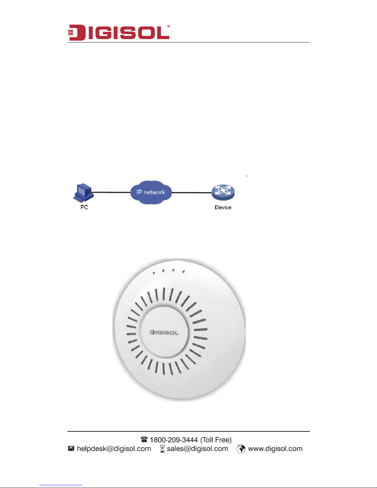
1.1 Overview
For the network administrator to configure and maintain to devices, this device provides
WEB network management function. The administrator can use WEB interface to manage
and maintain the network devices visually.
The running environment of Web network management is shown in fig 1-1.
Fig 1-1 Web The running environment of Web network management
1.2 Get Familiar with your new indoor Access Point
Page 7
DG-WM2001SI User Manual
7
1.3 Installation Precautions
Only allow the professionals installing and disassembling the device and its annex. Before
the installation and configuration, please read the related security introduction carefully.
Adopt the appropriate security measures to avoid the personal injury and
equipment damage.
Please put the device on the dry and flat place and ensure the anti-skid
measures.
Keep the device clean without dirt.
Do not place the device on a wet place and avoid the device touching any liquids.
Do not put the device and the installation tools in the walking area.
1.4 Installation Environment Requirements
Before the installation, please check the installation conditions of the device to make sure
that the device is in good operating environment for a long time. Check this with the
following aspects:
The temperature and humidity environment requirements of the device are as below:
Table 1-1 The temperature and humidity index
Items
Range
Standard working environment temperature (indoor)
-10℃~55℃
Storage temperature
-40℃~70℃
Working humidity (non-condensing)
5%~95%
1.5 Equipment Accessories
Please refer to the packing list.
Page 8

DG-WM2001SI User Manual
8
Package Contents
Before you start using this AC, please check if there’s anything missing in the package,
and contact your dealer of purchase to claim for missing items:
DG-WM2001SI (1 No.)
M3.5 Plastic stopper (4 Nos.)
Wall mounting bracket (1 No.)
T-Keel Mounting Kit (1 No.)
M3 fixing screws (3 Nos.)
M3 bolt (2 Nos.)
1.6 Installation Tools
When installing the indoorAP, the following tools may be used (user-owned).
Horizontal
ruler
Permanent
marker
Knife
Wire
stripper
Network pliers
Impact drill (1)
and some
supporting drills
Rubber
hammer
Phillips
screwdriver
Ladder
Page 9

DG-WM2001SI User Manual
9
1.7 Login Web Network Management
User can use the default information directly to login the web interface of the device.
The default Web login information includes:
User name: admin
Password:
IP address of the device: 192.168.1.10
The steps of web login:
(1) Connect the device to PC.
Use the cable to connect PC to the Ethernet interface of the device.
(2) Configure the IP address for PC and ensure that it can communicate with the device.
For example: Modify the IP address to 192.168.1.0/24.
(3) Launch the browser and input the login information.
Launch the browser on PC, and input “http://192.168.1.10” in the address bar and then
enter it. Enter into the web login page as shown in fig 1-2. Input the user name as admin
and password as blank, click “login” to login.
Page 10

DG-WM2001SI User Manual
10
Fig 1-7 Web network management login page
1.8 Quit Web Network Management
Click the “log off” button on the upper right corner on the Web network management page
to quit.
Page 11
DG-WM2001SI User Manual
11
1.9 Introduction to Page Layout of Web Network
Management
Web network management page includes: navigation bar, configuration area and help
area as shown in fig 1-8.
Fig 1-8 Initial page of Web network management
Navigation bar: Organize the Web network management menu by using the navigation
tree. User can choose the function menu in the navigation bar and the result will be shown
in the configuration area.
Configuration area: User can configure and check.
Help area: It provides the basic help information. The “more” button can check more help
information. And it provides the “log off” button to quit.
Page 12
DG-WM2001SI User Manual
12
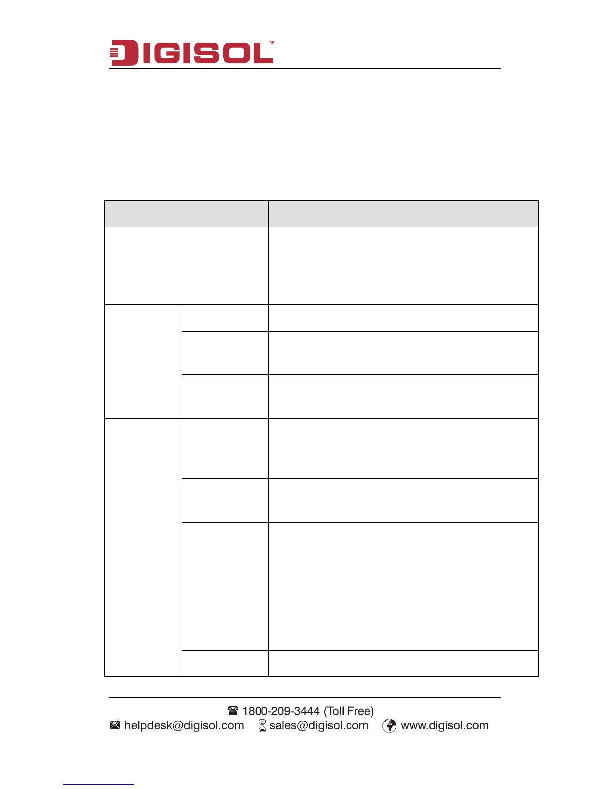
1.10 Introduction to Web Network Management
Function
The Web network management function explanation is given below in table 1-1:
Table 1-10 Web network management function explanation
Menu/label
Function explanation
Basic settings
Shows the AP address (IP address and MAC address),
version (firmware version) and device information. The
administrator password, serial ports configuration and
system settings can be configured.
Status
Network interface
Shows the real-time wired and wireless configuration of AP.
Transmit/Receive
Shows the virtual AP, enabling situation and the statistic of
transmitting and receiving packets of AP.
Client
association
Shows the information of transmitting and receiving packets
of the client which has been associated with AP.
Advance
Configuration
Ethernet settings
Configure the related wired configuration of AP including
host name, management vlan, untagged vlan, DHCP, static
IP and DNS server.
Wireless settings
Configure the related wireless configuration of AP including
country code, radio interface, physical mode and channel.
RF parameters
Configure the detailed RF parameters including radio
interface, physical mode, channel, channel bandwidth,
primary channel, supporting short protection interval or not,
STBC mode, protection, beacon frame interval, DTIM
interval, fragment threshold, RTS threshold, maximum
stations, transmission power, multicast rate and supported
rate.
Virtual AP
Configure the authentication mode of virtual AP and the
Page 13

DG-WM2001SI User Manual
13
related configuration.
Modes of AP
Configure the modes and IP address of AP.
System
maintenance
Configuration
management
Configure to restart AP and restore it to the factory
configuration. Import and export the files.
Firmware
upgrading
Configure the firmware upgradation of AP.
1.11 Introduction to Common Controls of Web Page
1. <Update> button
Click < Update> button to submit the input information.
2. <Refresh> button
Click <Refresh> button to refresh the information of the current page.
1.12 Usage Restriction of Web Network Management
(1) The operating systems supported by Web network management include: Windows XP,
Windows 2000, Windows Server 2003 Enterprise Edition, Windows Server 2003 Standard
Edition, Windows Vista, Windows 7, Linux and MAC OS.
(2) The browsers supported by Web network management include: Microsoft Internet
Explorer 6.0 SP2 and the versions above, Mozilla Firefox3.0 and the versions above,
Google chrome and Safari.
(3) Web network management does not support the “previous”, “next” and “refresh”
buttons from the browser. Using these buttons may cause the unusual page showing.
(4) Because the firewall of the Windows operating system will limit the number of
connected TCP, there will be the situation that the page cannot be opened when using
web network management occasionally. For avoiding this situation, we suggest to close
the firewall of the Windows.
(5) After the software version of the device has changed, we suggest to clear the cache
Page 14

DG-WM2001SI User Manual
14
data of the browser first during login the device through web network management.
Otherwise, the content of web network management may not be shown normally.
Page 15
DG-WM2001SI User Manual
15
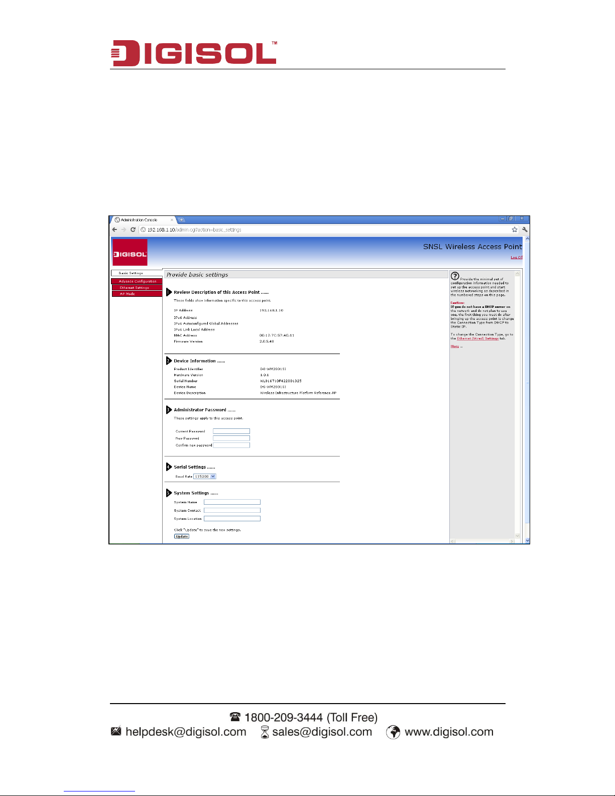
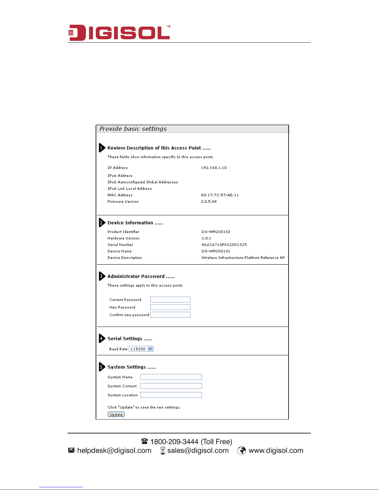
Chapter 2 Basic Configuration
Shows the basic configuration of the device and it includes the following content:
Review description of this access point, Device information; Administrator password;
Serial settings and System settings.
Page 16
DG-WM2001SI User Manual
16
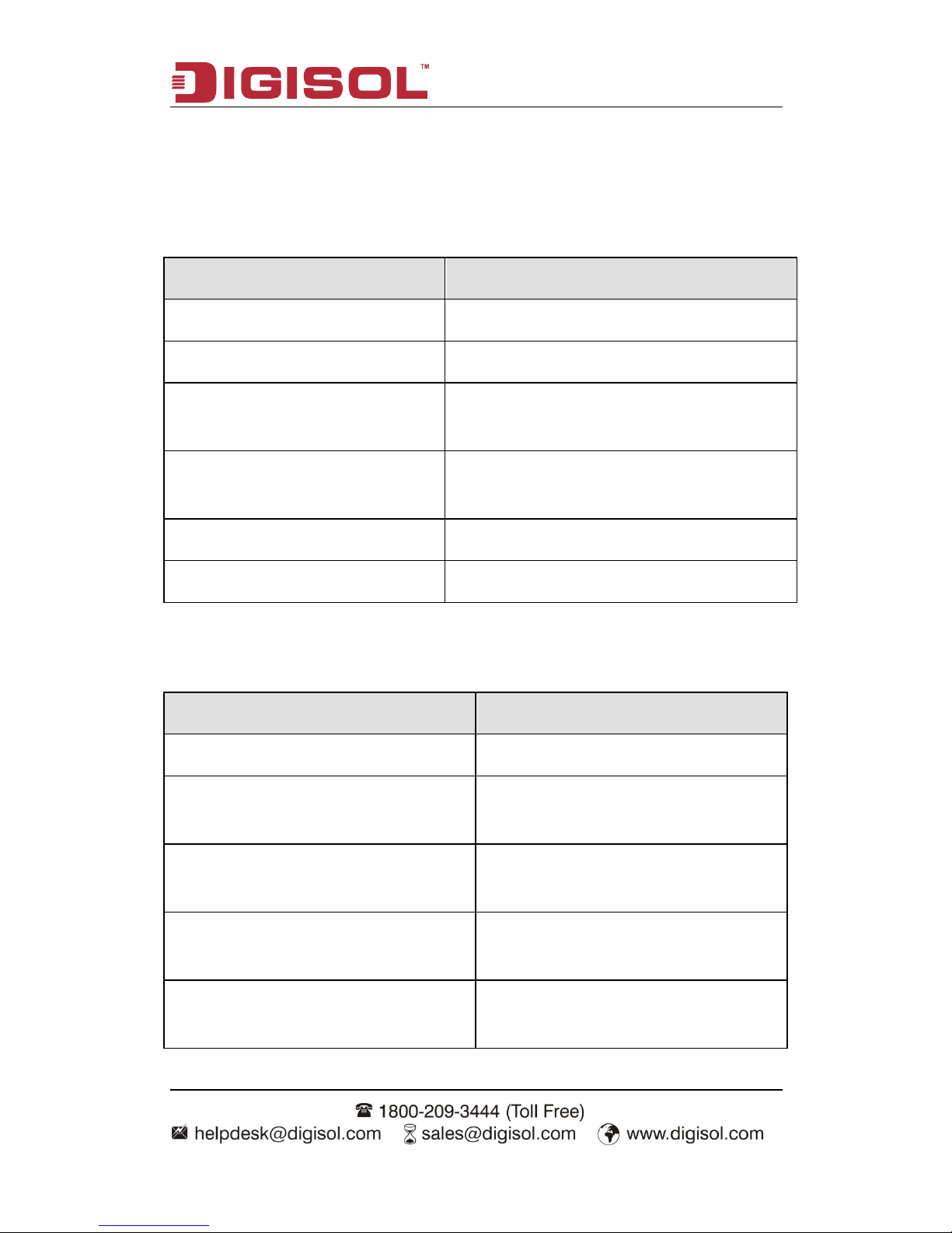
2.1 Detailed Explanation of settings
2.1.1 Description of this Access Point
Field
Description
IP Address
Shows the IP address of the current device.
IPv6 Address
Shows the IPv6 address of the current device.
IPv6 Autoconfigured Global Addresses
Shows the IPv6 auto configuredglobal address of
the current device.
IPv6 Link Local Address
Shows the IPv6 link local address of the current
device.
MAC Address
Shows the MAC address of the current device.
Firmware Version
Shows the firmware version of the current device.
2.1.2 Device Information
Field
Description
Product identifier
Shows the product ID of the current device.
Hardware version
Shows the hardware version of the current
device.
Serial number
Shows the serial number of the current
device.
Device name
Shows the device name of the current
device.
Device description
Shows the device description of the current
device.
Page 17

DG-WM2001SI User Manual
17
2.1.3 Administrator Password
Field
Description
Current password
Input the current administrator password.
New password
Input the new password.
Confirm new password
Input the new password again and it must
be same as the above new password.
2.1.4 Serial Settings
Field
Description
Baud Rate
Configure the baud rate of the serial ports.
2.1.5 System Settings
Field
Description
System name
Configure the system name.
System contact
Configure the contact.
System location
Configure the device location.
Page 18

DG-WM2001SI User Manual
18
Chapter 3 Current Status
The current status includes network information, statistic of transmitting and receiving
packets and the client association.
3.1 Network Information
3.1.1 Wired Settings
Field
Description
MAC address
Shows the MAC address of the current
device.
Management VLAN ID
Shows the vlan ID of the current device.
IP address
Shows the IP address of the current device.
Page 19

DG-WM2001SI User Manual
19
Subnet mask
Shows the subnet mask of the current
device.
IPv6 Address
Shows the IPv6 address of the current
device.
Static IPv6 Address Prefix Length
Shows the prefix length of static IPv6
address.
IPv6 Auto configured Global Addresses
Shows the IPv6 auto configured global
addresses of the current device.
IPv6 Link Local Address
Shows the IPv6 link local address of the
current device.
IPv6 DNS Server-1
Shows the IPv6 DNS server-1 of the current
device.
IPv6 DNS Server-2
Shows the IPv6 DNS server-2 of the current
device.
Default IPv6 Gateway
Shows the default IPv6 gateway of the
current device.
DNS-1
Shows the IP address of DNS-1 server of
the current device.
DNS-2
Shows the IP address of DNS-2 server of
the current device.
Default gateway
Shows the default gateway of the current
device.
Page 20

DG-WM2001SI User Manual
20
3.1.2 Wireless Settings
Field
Description
MAC address
Shows the MAC address information of
RF1 or 2.
Mode
Shows the wireless mode information of
RF1 or 2.
Channel
Shows the channel information of RF1 or 2.
3.1.3 Explanation
Click the “Edit” link in the wired and wireless configuration to link to the wired and wireless
configuration page directly.
3.2 Statistic for Transmitting and Receiving IP Traffic
3.2.1 Device Information Status
Shows all the physical ports and the status of virtual AP.
Page 21

DG-WM2001SI User Manual
21
Field
Description
Interface
The name of Ethernet interface or VAP interface.
Status
Mark the interface is up or down.
MAC address
MAC address of the specific interface.
Every interface of AP has the unparalleled MAC address.
Each interface of each RF of the two RF has a different MAC
address.
VLAN ID
VLAN ID
You can use VLAN to create multiple internal and customer
networks on the same AP.
VLAN ID is configured in VAP label.
Network name (SSID)
Wireless network name. it is also named as SSID which is
used to mark the WLAN.
SSID is configured in VAP label.
Page 22

DG-WM2001SI User Manual
22
3.2.2 Transmit/Receive Packets
Field
Description
Interface
The name of Ethernet interface or VAP interface.
Packets number
Shows the number of the packets that the AP sent (in
the transmitting packet table) or received (in the
receiving packet table).
Bytes number of packets
Shows the number of bytes that the AP sent (in the
transmitting packet table) or received (in the
Page 23

DG-WM2001SI User Manual
23
receiving packet table).
Dropped packets number
Shows the number of the sent (in the transmitting
packet table) or received (in the receiving packet
table) packets that the AP dropped.
Bytes number of dropped packets
Shows the number of the sent (in the transmitting
packet table) or received (in the receiving packet
table) bytes that the AP dropped.
Error statistics
Shows the total error number of AP transmitting and
receiving data.
3.3 Client Associations
Client association showing:
Field
Description
Network
The SSID of the client associated
network.
Station
The MAC address of the associated
client.
Status
Authenticated
The status of authenticated means the
IEEE 802.11 authentication status.
Associated
The status of associated means the
IEEE 802.11 association status.
From station
Packets
It means that the number of packets
and bytes received from the client and
the number of dropped packets and
Bytes
Page 24

DG-WM2001SI User Manual
24
Dropped packets
bytes after received.
Dropped bytes
To station
Packets
It means that the number of packets
and bytes client received and the
number of dropped packets and bytes
in transmission.
Bytes
Dropped packets
Dropped bytes
Page 25

DG-WM2001SI User Manual
25
Chapter 4 Advance Configuration
The “Advance configuration” includes Ethernet settings, wireless settings, RF parameters,
virtual AP, WDS and AP modes.
4.1 Ethernet Settings
Field
Description
Host name
The host name of AP.
MAC Address
The MAC address of the Ethernet interface of AP.
Page 26

DG-WM2001SI User Manual
26
Management VLAN ID
The management VLAN is used to access the
VLAN which is associated with the IP address of
AP.
Untagged VLAN
If the untagged VLAN was disabled, all the
packets will be marked with the same VLAN
number.
Untagged VLAN ID
The packet transmitted in this VLAN has no
tagged VLAN number.
Connection Type
Configure the IP address obtaining of AP.
Static IP Address
Configure the static IP address. If the IP obtaining
is DHCP, this property cannot be used.
Subnet Mask
Configure the subnet mask. If the IP obtaining is
DHCP, this property cannot be used.
Default Gateway
Configure the default gateway. If the IP obtaining
is DHCP, this property cannot be used.
DNS Server
Configure the DNS mode. Under the manual
appointed mode, the DNS address can be
configured to analyze the domain name.
IPv6 Admin Mode
Configure the getting mode of IPv6.
IPv6 Auto Config Admin Mode
Configure the IPv6 automatic address. If it is
disabled, this function is not enabled.
IPv6 Connection Type
Configure the mode of getting the IPv6 address.
Static IPv6 Address
Configure the static IPv6 address of AP.
Static IPv6 Address Prefix Length
Configure the prefix length of static IPv6 address.
IPv6 Auto configured Global Addresses
Show the IPv6 auto configured global addresses.
IPv6 Link Local Address
Show the IPv6 link local address of AP.
Page 27

DG-WM2001SI User Manual
27
Default IPv6 Gateway
Show the default IPv6 gateway of AP.
IPv6 DNS Server
Configure the address getting mode of DNS
server of IPv6; configure the static IPv6 DNS
server address.
4.2 Wireless Settings
Field
Description
Country
Choose the country of AP.
Radio interface 1/Radio interface 2
The RF device can be enabled or disabled here.
MAC address
The MAC address of the RF interface.
Mode
The Physical Layer standard the radio uses.
Channel
Choose the channel.
Page 28

DG-WM2001SI User Manual
28
4.3 RF Parameters
Page 29

DG-WM2001SI User Manual
29
Field
Description
Radio
Choose the configured RF.
Status
Enable/disable the RF.
Mode
The PHY standard used by RF.
Channel
Choose the channel.
Channel bandwidth
The channel bandwidth of 802.11n mode.
Primary channel
The mode of the primary channel (only the 802.11n
mode is supported)
Short guard interval supported
Configure the short guard.(only the 802.11n mode is
supported)
STBC mode
Configure the STBC mode.(only the 802.11n mode
is supported)
Protection
Configure the protection function.
Beacon interval
Configure the Beacon interval.
DTIM interval
Configure the DTIM interval.
Fragment threshold
Configure the fragment threshold.
RTS threshold
Configure the RTS threshold.
Maximum stations
Configure the maximum number of associated
stations.
Transmit power
Configure the percentage of the RF transmission
power.
Fixed Multicast rate
Configure the supported multicast rate.
Rate sets
Configure the transmission rate set and the basic
broadcast rate set that is supported by RF.
Page 30

DG-WM2001SI User Manual
30
4.4 Virtual AP
Page 31

DG-WM2001SI User Manual
31
Field
Description
Radio
Choose the configured RF.
VAP
Show the ID number of the virtual AP.
Enabled
Configure the status of the virtual AP.
VLAN ID
Configure the VLAN that the client associated with the virtual AP
belongs to.
SSID
Configure the name of wireless network.
Broadcast SSID
Configure the broadcast SSID.
Security
Configure the security mode.
4.4.1 None Security Configuration
Choose the security configuration as none, the security configuration will not be needed in
clients association; it can be associated with the virtual AP directly.
Page 32

DG-WM2001SI User Manual
32
4.4.2 Static WEP Security Configuration
Choose the security configuration as static WEP and show the detailed configuration
information of static WEP security configuration. The direct key should be input in the
client to pass the authentication or the decryption packet.
Field
Description
Transfer key index
Configure the key index.
Key length
Configure the length of the key.
Key type
Configure the type of key.
WEP keys
Configure the key 1-4.
Authentication
Configure the authentication mode.
Page 33

DG-WM2001SI User Manual
33
4.4.3 WPA Personal Security Configuration
Choose the security configuration as WPA Personal and show the detailed configuration
information of WPA Personal security configuration. The direct key should be input in the
client to pass the authentication.
Field
Description
WPA versions
Configure the WPA version.
Cipher suites
Configure the cipher suites.
Key
Configure the key.
Broadcast key refresh key
Configure the interval of broadcast key updating.
Page 34

DG-WM2001SI User Manual
34
4.4.4 WPA Enterprise Security Configuration
Choose the security configuration as WPA Enterprise and show the detailed configuration
information of WPA Enterprise security configuration. The direct user name and password
existed in radius server should be input in client to pass the authentication.
Field
Description
WPA version
Configure the WPA version.
Cipher suites
Configure the cipher suites.
Radius IP address
Configure the IP address of radius server.
Radius IP address1-3
Configure the IP address of the backup radius
server.
Radius key
Configure the radius server key.
Radius key 1-3
Configure the key of the backup radius server.
Active server
Choose the radius server.
Broadcast key refresh rate (0-86400)
Configure the interval of broadcast key updating.
Session key refresh rate (0-86400)
Configure the interval of unicast key updating.
Page 35

DG-WM2001SI User Manual
35
4.4.5 WDS
Page 36

DG-WM2001SI User Manual
36
4.5 AP Modes
The AP modes can be switched on this page. Configure the address of Access Controller
and the password of AP authentication under Mode Fat.
Field
Description
Management AP administrative mode
Configure the AP modes.
Switch IP address of 1-4
Configure the IP address of AC under the fat AP
mode.
Switch IPv6 address of 1-4
Configure the IPv6 address of AC under the fat
AP mode.
Pass phrase
Configure the password of the associated
authentication between AP and AC under the fat
AP mode.
Page 37

DG-WM2001SI User Manual
37
Chapter 5 System Maintenance
The system maintenance includes configuration management and firmware upgradation.
5.1 Configuration Management
Click “reset” button to restore the configuration of AP to default. The default working mode
of AP is fit AP mode.
Choose the download method as HTTP mode, click “download” button and confirm it,
then the current configuration files of AP will be downloaded through HTTP directly.
Choose the download method as TFTP mode, input the file name of the configuration file
(the format is *.xml) and the IP address of TFTP server. Then click “download” button and
confirm it. The configuration file will be downloaded to the appointed TFTP server and the
Page 38

DG-WM2001SI User Manual
38
file name is the input name.
When the upload method was chosen as HTTP mode, click “browse” button to choose the
configuration file (the format is *.xml) which needs to be uploaded. Confirm it and click
“restore” button. The current configuration of AP will be restored to the configuration in the
uploaded configuration file.
When the upload method was chosen as TFTP mode, input the file name of the
configuration file (the format is *.xml) and the IP address of TFTP server. Click “restore”
button and confirm it. The current configuration of AP will be restored to the configuration
in the uploaded configuration file.
Click “reboot” button and confirm it. Then the AP will be restarted.
Page 39

DG-WM2001SI User Manual
39
5.2 Firmware Upgrading
Complete the firmware upgradation of AP by using HTTP through the following steps:
1. Choose the HTTP as the upgrading method.
2. If you knew the path of the new firmware file, input this path in the text box. Otherwise,
click the “browse” button to locate the upgrading file of firmware.
The upgrading file of firmware must be the tar file. Please do not try to use the bin file or
other kinds of files to upgrade; these files would not run.
3. Click the “firmware upgrading” button to apply the new firmware file.
After clicked the “firmware upgrading” button, there will be a window which describes the
upgrading process.
4. Click the “confirm” button to confirm to upgrade and start the upgrading process.
Notice: Click the “firmware upgrading” button and confirm it in the window. The
upgrading process will start.
The upgrading process will be continued for a few minutes. During this period, AP cannot
be accessed. Please do not turn off the AP power in upgrading. After upgrading, AP will
restart. After restarted, AP will use the configuration before upgrading still.
Platform
Version of firmware
Show the version of firmware of the current AP.
Page 40

DG-WM2001SI User Manual
40
5. Ifyou want to known whether the firmware upgradation was successful, please check
the firmware version in the firmware management page (or the basic configuration label).
If the upgradation was successful, the version after upgrading will be shown.
Complete the firmware upgradation of AP by using TFTP through the following steps:
1. Choose TFTP as the uploading method.
2. Input the name of the mirror file in the text box (1 to 256 characters). The name includes
the integral path of the mirror file.
For example, if the file of ap_upgrade.tar in the content of /share/builds/ap needs to
be uploaded, input “/share/builds/ap/ap_upgrade.tar” in the text box.
The upgrading file of firmware must be the tar file. Please do not try to use the bin file or
other kinds of files to upgrade; these files would not run.
3. Input the IP address of the TFTP server.
4. Click the “firmware upgrading” button.
After clicked the “firmware upgrading” button, there will be a window which describes the
upgrading process.
5. Click the “confirm” button to confirm to upgrade and start the upgrading process.
Notice: click the “firmware upgrading” button and confirm it in the window. The
upgrading process will start.
The upgrading process will be continued for a few minutes. During this period, AP cannot
be accessed. Please do not turn off the AP power in upgrading. After upgrading, AP will
restart. After restarted, AP will use the configuration before upgrading still.
Page 41

DG-WM2001SI User Manual
41
6. If you want to known whether the firmware upgradation was successful, please
check the firmware version in the firmware management page (or the basic configuration
label). If the upgradation was successful, the version after upgrading will be shown.
Page 42

DG-WM2001SI User Manual
42
Chapter 6 Configuration Examples
6.1 Laws Wireless Access
6.1.1 Networking Requirements
A department needs to achieve the mobile office through deploying AP for that the
staffs can visit the internal network resources anytime and anywhere. The device
administrator can configure the laws wireless access and the detailed demand is as
below:
AP provides the wireless access service with SSID as the laws method of “service”.
For meeting the high bandwidth demands and the compatible 802.11g wireless
network, adopt the 802.11n (2.4GHz) RF mode.
Fig 1-11 laws wireless access
6.1.2 Configuration Steps
1. Login the AP configuration page and enter into the wireless configuration page.
Page 43

DG-WM2001SI User Manual
43
Choose “enable” for Radio Interface 1.
Choose IEEE 802.11b/g/n for the wireless mode.
Choose the default configuration for channel.
Click “submit” button.
2. Enter into the virtual AP configuration page.
Choose the virtual AP enabled box (the virtual AP 0 is enabled as default.)
Configure the VLAN ID according to the actual situation.
Configure SSID as “service”.
Use the default configuration for “broadcast SSID”.
Choose “None” for the security configuration.
Click “submit” button.
Page 44

DG-WM2001SI User Manual
44
6.1.3 Test the Configuration Results
Enter into the client association page to view the successful on-line clients.
6.2 Cipher Wireless Access of Static-WEP
(Open-System)
6.2.1 Networking Requirements
In a small office, the device administrator can complete the WEP (Open-System)
cipher configuration through the web page. The detailed demand is as below:
AP provides the WEP (Open-System) cipher wireless access service with SSID as
“WEP”.
For meeting the high bandwidth requirements and the compatible 802.11g wireless
network, adopt the 802.11n (2.4GHz) RF mode.
Fig 1-14 WEP(Open-System) cipher wireless access
6.2.2 Configuration Steps
1. Login the AP configuration page and enter into the wireless configuration page.
Page 45

DG-WM2001SI User Manual
45
Choose to enable for RF1.
Choose IEEE 802.11b/g/n for the wireless mode.
Use the default configuration for the channel.
Click “submit” button.
2. Enter into the virtual AP configuration page.
Choose the virtual AP enabled box (the virtual AP 0 is enabled as default.)
Configure the VLAN ID according to the actual situation.
Configure SSID as “WEP”.
Use the default configuration for “broadcast SSID”.
Choose “Static WEP” for the security configuration.
Configure the key index as 1.
Configure the length of key as 64bits.
Configure the key type as ASC II.
Configure the WEP key 1 as 12345.
Configure the authentication method as “open system”
Click “submit” button.
Page 46

DG-WM2001SI User Manual
46
6.2.3 Test the Configuration Results
Enable the wireless client and refresh the network list. Find the configured network
service in the list of “choose wireless network” (it is PSK in this example). Click
“connect” and input the WEP key as 12345 in the dialog box (the input WEP key
must be the same as the configured WEP key on the device). After associated with
the AP successfully, user can access the wireless network.
Enter into the client association page and the successful online clients can be viewed.
6.3 WPA2-PSK Wireless Access
6.3.1 Networking Requirements
In a small office, the device administrator can complete the WPA2-PSK wireless
access configuration through the web page. The detailed demand is as below:
AP provides the WPA2-PSK wireless access service with SSID as “psk”.
For meeting the high bandwidth requirements and the compatible 802.11g wireless
network, adopt the 802.11n (2.4GHz) RF mode.
Fig 1-18 WPA2-PSK wireless access
Page 47

DG-WM2001SI User Manual
47
6.3.2 Configuration Steps
1. Login the AP configuration page and enter into the wireless configuration page.
Choose to enable for RF1.
Choose IEEE 802.11b/g/n for the wireless mode.
Use the default configuration for the channel.
Click “submit” button.
2. Enter into the virtual AP configuration page.
Choose the virtual AP enabled box (the virtual AP 0 is enabled as default.)
Configure the VLAN ID according to the actual situation.
Configure SSID as “psk”.
Use the default configuration for “broadcast SSID”.
Choose “WPA Personal” for the security configuration.
Click to choose WPA2 for the WPA version according to the requirement and cancel
the WPA.
Use the default configuration for the cipher suites.
Page 48

DG-WM2001SI User Manual
48
Configure the key 1 as 12345678.
Use the default configuration for the broadcast key refresh rate.
Click “submit” button.
6.3.3 Test the Configuration Results
Enable the wireless client and refresh the network list. Find the configured network
service in the list of “choose wireless network” (it is PSK in this example). Click
“connect” and input the pre-shared key as 12345678 in the dialog box (the input
pre-shared key must be the same as the configured pre-shared key on the device).
After associated with the AP successfully, user can access the wireless network.
Enter into the client association page and the successful online clients can be viewed.
6.4 WPA2-Enterprise Wireless Access
6.4.1 Networking Requirements
In an office building of a company, the staffs need to access the office environment
through the wireless network; the other mobile devices that do not belong to the staffs
cannot be accessed. The administrator can configure the WPA2-Enterprise through the
web page. The detailed demand is as below:
AP provides the WPA2-Enterprise wireless access service with SSID as
“WPA-Enterprise”.
For meeting the high bandwidth requirements and the compatible 802.11g wireless
network, adopt the 802.11n (2.4GHz) RF mode.
Page 49

DG-WM2001SI User Manual
49
Fig 1-19 WPA2-Enterprise wireless access
6.4.2 Configuration Steps
1. Login the AP configuration page and enter into the wireless configuration page.
Choose to enable for RF1.
Choose IEEE 802.11b/g/n for the wireless mode.
Use the default configuration for the channel.
Click “submit” button.
Page 50

DG-WM2001SI User Manual
50
2. Enter into the virtual AP configuration page.
Choose the virtual AP enabled box (the virtual AP 0 is enabled as default.)
Configure the VLAN ID according to the actual situation.
Configure SSID as “WPA-Enterprise”.
Use the default configuration for “broadcast SSID”.
Choose “WPA Enterprise” for the security configuration.
Click to choose WPA2 for the WPA version according to the requirement and cancel
the WPA.
Use the default configuration for the cipher suites.
Configure the Radius IP address according to the actual requirements; it is configured
as “192.168.1.234” in this example.
Configure the Radius key according to the actual requirements; it is configured as
“test”.
Choose the server and configure it as Radius IP address.
Use the default configuration for the broadcast key refresh rate.
Use the default configuration for the unicast key refresh rate.
Click “submit” button.
Page 51

DG-WM2001SI User Manual
51
6.4.3 Test the Configuration Results
Enable the wireless client and click the “modify the advanced configuration”; choose
the wireless network configuration in the window. Choose to use the windows to
configure my wireless network configuration and click “add” button; input
“WPA-Enterprise” in the window of SSID. Choose WPA2 for the network
authentication in the key and choose AES for the data cipher; and then click to
confirm it. Choose the added first choice of network and click “property“; and then
click “authenticate”. Choose the “protected EAP (PEAP)” for the EAP types and
cancel that “authenticate as computer when the computer information is useful”, click
“property”; and then cancel “authentication server”. Choose the “EAP-MSCHAP v2”
for the authentication and click “property”; and then cancel using the login name and
password (and the domain if it exists) automatically and click to confirm it. Enable the
wireless client again and refresh the network list. Find the configured network service
in the list of “choose wireless network” (it is WPA-Enterprise in this example). Click
“connect” and input the user name and password existed in Radius server in the
dialog box. After associated with the AP successfully, user can access the wireless
network.
Enter into the client association page and the successful online clients can be viewed.
This product comes with One Year warranty. For further details about warranty policy
and Product Registration, please visit support section of www.smartlink.co.in
 Loading...