

Page 1
RANGER SERIES
300Mbps CEILING MOUNT
ACCESS POINT
DG-WM2005SI
300 Mbps
N
V1.0
2014-05-19
Page 2

FCC Interference Statement:
This equipment has been tested and found to comply with the limits for a
Class B digital device pursuant to Part 15 of the FCC Rules. These limits are
designed to provide reasonable protection against radio interference in a
commercial environment. This equipment can generate, use and radiate
radio frequency energy and, if not installed and used in accordance with
the instructions in this manual, may cause harmful interference to radio
communications. Operation of this equipment in a residential area is likely
to cause interference, in which case the user, at his own expense, will be
required to take whatever measures are necessary to correct the
interference.
CE Declaration of Conformity:
Thi s e quip men t c ompl ies wi th the r equ irement s r elating to
electromagnetic compatibility, EN 55022/A1 Class B.
Copyright
Copyright 2014 by Smartlink Network Systems Ltd.All rights reserved. No
part of this publication may be reproduced, transmitted, transcribed,
stored in a retrieval system, or translated into any language or computer
language, in any form or by any means, electronic, mechanical, magnetic,
optical, chemical, manual or otherwise, without the prior written
permission of this company.
Trademarks:
TM
DIGISOL is a trademark of Smartlink Network Systems Ltd. All other
trademarks are the property of the respective manufacturers.
Page 3

Package Contents
The following items should be present in your package:
DG-WM2005SI Ceiling Mount Access Point
DC 12V Power Adapter
Patch Cord
Installation Guide CD
Make sure that the package contains above items. If any of the listed items
is damaged or missing, please contact your retailer immediately.
Product Overview
Congratulations on your purchase of this outstanding product DGWM2005SI WiFi 2.4G N 300 Ceiling Access Point designed for small- and
medium-sized businesses to extend the existing wired networks and has
the ability to operate in different modes and can be used in a wide variety of
wireless applications like AP, Point-to-Point. Universal Repeater Mode not
only has an easier setup method, but also provides better performance and
compatibility to create a virtually larger wireless network infrastructure by
linking up other access points.
Support Multiple-SSID capability to use one Physical AP to simultaneously
emulate 8 APs with different ESSIDs by separate packets via VLAN
technology.
Product Features
Page 4
System requirements
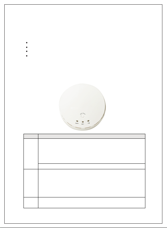
LED
Description
Status
When the device is booted up and ready:
When WEC/Reset is triggered (with button pressed):
Status LED flashes at different rate according button-pressed duration.
Stage 1 (1 ~ 5 sec) : Flash very fast
Stage 2 (6 ~ 10 sec) : Flash twice per second
Stage 3 (11~15 sec) : Flash once per second
Stage 4 (16~30 sec) : Solid Green
OFF: The device is powered off.
WiFi
Green LED : Device is in Master Mode
Amber LED: Device is in Slave Mode
LED flash: data packet transferred.
LED in fast flash per second during 2min: WPS PBC status
OFF: Wireless Radio is disabled.
LED in slow flash or Flash Green and Amber Alternately : Wireless
Connection doesn't establish.
LED in Solid: Wireless Connection established successfully.
LAN
OFF: No Ethernet connection.
Solid Green: Ethernet connection is linked up.
Flash Green: Data packet is transferred over the Ethernet link.
The following system requirements are recommended:.
An Ethernet based cable or DSL modem
Windows, Macintosh or Linux based operating system
CD-ROM drive
IE 6.0 or higher, Chrome 2.0, Firefox 3.0, Safari 3.0
Product View
Below shown is the product view indicating the LED status.
Page 5
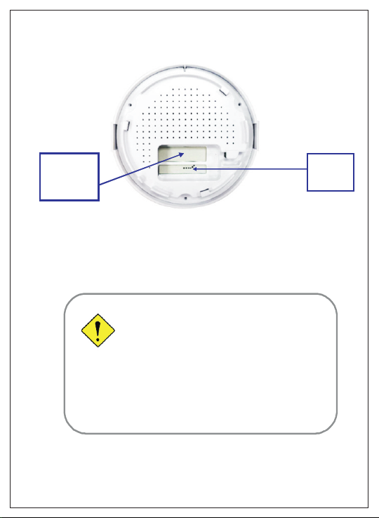
Rear View
PoE-PD
Ethernet
Port
Hardware Installation
Warning
Attention
l
Do not use the product in high humidity or high
temperatures.
l
Do not use the same power source for the Product
as other equipment. Only use the power adapter
that comes with the package. Using a different
voltage rating power adaptor may damage the
device.
l
Do not open or repair the case yourself. If the
Product is too hot, turn off the power immediately
and have it repaired at a qualified service center.
l
Place the Product on a stable surface and avoid
using this product and all accessories outdoors.
Receptor for
Power
Adapter
Page 6
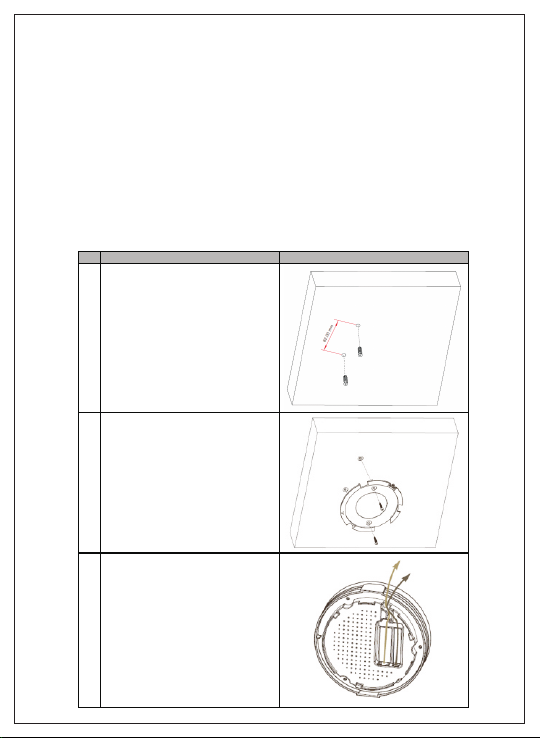
Mounting on the Ceiling/Wall
Description
Illustration
A Drill 2 holes for wall plugs.
Self-tapping screws (Diameter : 3mm)
If you run the cable above the ceiling
(invisible cabling), you have to drill
another big hole ( about 10~20 mm
diameter) to pull out the cable for
connecting to the device.
B Screw the mounting bracket on the
ceiling / wall.
C Plug-in the cable (Ethernet c able,
Power cord) to the connectors in the
button side.
Run the cables upward to proper
location.
This device is designed for easily mounted on the ceiling or wall with a
simple mount bracket. Before mounting it to the expected location, please
make proper configuration for the device setting and run the PoE Ethernet
cable to the location in advance.
The following illustrations show you how to mount this device on the
ceiling / wall.
Page 7
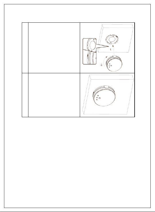
D Attached this device to mo unting
bracket by r otating it clock wisely to
click into place.
E Installation completed.
Page 8

Function
Button
Description
Easy
Configuration
(Master to Slave)
WEC/Reset
(Press 3 sec)
There are two alternative AP modes defined for the
device to operate wit h W EC (Wireless Easy
Connection) feature. One is Master Mode (by
default), and the other is Slave Mode.
Please manually configure the Wireless Setting for
the Master AP through web UI fir st, and also
prepare a Slave AP that already been set to Slave
Mode.
1. Press the WEC/Reset button of the Master AP
for 1~3 seconds, release it to trigger the WEC
process. Then, the WiFi LED flashes fast.
2. Press the WEC/Reset button of the Slave AP
for 1~3 seconds, release it to trigger the WEC
process. Then, the WiFi LED flashes fast.
Note: The Slave AP must be an un-configured
one, i f it has already been paired and
configured b efore, please reset its Slave
configuration first.
3. After a few seconds (normally about 30~60
seconds). T he Master and Slave APs can be
paired automatically, and auto-d uplicates the
VAP1 wireless setting of the Master AP as that
of the Slave AP.
(If th ere is something wrong during paring the
two devices, the process will be finished in 2
minutes.)
4. Once the easy configuration process
completed, the Status LED will be recovered to
its original behavior (prior to you triggered it).
And the WiFi L ED will be Solid Green when
Slave AP is connected to the network.
Easy
Configuration
(Slave to Slave)
WEC/Reset
(Press 3 sec)
Besides the above “Mast er to Slave” configuration,
the easy c onfiguration process also supports
“Slave to Slave” configuration.
1. Press the WEC/Reset button of the first Slave
AP (s ay Slave1 that has been paired and
configured) for 1~3 seconds, release it to
trigger th e WEC process. Then, the WiFi LED
flashes fast.
2. Press the WEC/Reset button of the second
Slave AP (say Slave2 that is an un-configured
Slave AP) for 1~3 seconds, release it to tr igger
the WEC process. Then, the WiFi LED flashes
fast.
3. After a few seconds (normally about 30~60
seconds). The Slave1 and Slave2 APs can be
paired automatically, and auto-d uplicates the
wireless setting of the Slave1 as that of the
Slave2.
(If th ere is something wrong during paring the
two devices, the process will be finished in 2
Button Definition
There is one multi-function push button "WEC/Reset" in this device.
According to different button pressed duration, the device will take
specific reaction. For ease of interacting with the device, you can also
check the Status LED to determine when to release the button.
The Reset/WEC button's behavior is defined below:
Page 9

AP Mode
Toggling
WEC/Reset
(Press 8 sec)
There are two alternative AP modes defined for the
device to operat e with W EC (Wireless Easy
Connection) feature. One is Master Mode (by
default), and the other is Slave Mode.
To change the AP mode from one to t he other, you
have to:
1. Press the WEC/Reset button for 6~10 seconds,
and then release it.
2. The WiFi LED becomes OFF in 3 ~ 5 seconds,
3. After about 20 ~ 25 seconds, the WiFi L ED will
be lit ON again to indicate th at the AP Mode is
changed.
It takes about 36 seconds to change (toggle) the
AP Mode completely.
WiFi Green LED : Device is in Master Mode
WiFi Amber LED: Device is in Slave Mode
Reset Slave AP
Configuration
WEC/Reset
(Press 13
sec)
1. Press the W EC/Reset button for about 11~15
seconds and release it.
2. The Slave AP will be marked as an unconfigured device, so that it can be paired with
another Master or configured Slave AP later.
For Master AP, th ere is no effect on this b utton
behavior.
Reset to Default
WEC/Reset
(Press 20
sec)
1. Press the Reset/WEC button for about 20
seconds t il l the Status LED becomes solid
Green to i ndicate that the reset to default
function is triggered. Release the button.
2. Then, the device will reb oot automatically and
apply the factory default settings as well.
It takes a bout 2 minutes to finish the reset to
factory default operation.
Page 10

Getting Started
Before you can install this product to designated location and make it
operate properly, you have to configure the device setting to fit in your
network environment.
Hardware Preparation:
a. Connect an Ethernet cable between this device and the
computer that you will operate to set up the device.
b. Power on the device via connecting the power adaptor DC
Plug to the DC Jack of this device and plug in the power adaptor to an
electrical outlet.
Page 11

Software Preperation
Most computers are connecting to a local network with dynamic IP (DHCP)
setting. To access the web UI of the device, you have to change your
computer's TCP/IPv4 settings into a static IP setting for the Ethernet
Interface. You can refer to Appendix A for how to assign a Static IP address
you your computer.
The device's default IP address is 192.168.123.50, and your computer must
be assigned with a 192.168.123.x IP address to get access to the device.
Referring to Appendix A, and set the TCP/IPv4 address of your computer to
192.168.123.25, and subnet mask to 255.255.255.0.
After applying this setting, you can now access to the web UI for
configuring the device.
Page 12

Easy Set up via Web UI
You can browse web UI to configure the device. Firstly you need to launch
the Setup Wizard browser first and then the Setup Wizard will guide you
step-by-step to finish the basic setup process.
Activate the setup wizard
Type in the IP Address (http://192.168.123.50)
Type the default password "admin" in the system authentication fields,
and then click 'login' button.
Select your language.
Select "Wizard" for basic settings in a simple way.
Or, you can go to Basic Network / Advanced Network / Applications /
System to setup the configuration by your own selection.
Page 13

Press "Next" to start the Setup Wizard.
Configure with Setup Wizard
Step 1 You can change the password of administrator here..
Step 2 LAN IP Address.You have to change the IP address of this device
according to your network configuration.
Page 14

Step 3-1 Wireless settings.You can specify the Wireless setting for VAP1.
Step 3-2 Wireless settings. Specify VAP1's wireless authentication and
encryption.
Page 15

Step 4 Check the information again.
Step 5 System is applying the setting.
Step 6 Click finish to complete it.
Page 16

Use WEC button to setup wireless profiles
WEC (Wireless Easy Connection) is an easy configuration feature that is
similar to well-known WPS function. It can be used to duplicate one
device's wireless configuration to the other AP devices from the same
manufacture by clicking one button for both devices.
There are two alternative AP modes defined for the device to operate with
WEC (Wireless Easy Connection) feature. One is the Master Mode (by
default), and the other is the Slave Mode. Before starting to use WEC to
configure your AP devices, you have to learn how to identify and set the
device in the Master Mode, or the Slave Mode (As stated in Section 1.2.4
and 1.2.5).
One Master and several isolated Slaves
As illustrated in above figure, how to configure the three APs (AP1, AP2,
AP3) to build up the "staff" wireless network? You can follow the
procedure bellow:
Page 17

Step
Button
Description
1
Set AP1 in Master Mode,
and configure it via web
UI.
1. Make sur e AP1 is in Master Mode (WiFi LED
should be “Green” color, if not, you have to
toggle i ts AP mode via pressing the WEC
button for 9~10 seconds)
2. Login in to AP1 web UI and c onfigure the
wireless settings as what you want (LAN IP,
SSID, encryption key, etc..).
2
Set AP2 and AP3 in
Slave Mode.
1. Make sure AP2 / AP3 is in Slave Mode (WiFi
LED should be “Amber” color, if not, you have
to toggle its AP mode via pressing the WEC
button for 9~10 seconds)
3
Easy configure AP2 via
WEC.
Master to Slave WEC:
1. Trigger AP1 into WEC configuration process via
pressing the WEC button for 3 second.
2. Trigger AP2 into WEC configuration process via
pressing the WEC button for 3 second.
3. It takes 30 ~ 60 s econds for the device to finish
the WEC configuration process.
4
Easy configure AP3 via
WEC.
Master to Slave WEC:
1. Trigger AP1 into WEC configuration process via
pressing the WEC button for 3 second.
2. Trigger AP3 into WEC configuration process via
pressing the WEC button for 3 second.
3. It takes 30 ~ 60 s econds for the device to finish
the WEC configuration process.
5
Mount the devices AP1,
AP2, and AP3 to
expected locations.
1. Install AP1 to its location fi rst and verify its
wireless network connectivity with a client
device (Client3).
2. Install AP2 to its location and verify its wireless
network connectivity with a c lient device
(Client4) at the location beyond the service
range of AP1.
Besides, You can also check the AP2’s WiFi
LED, it s hould be “Solid Amber” if AP2 already
connected a Master AP AP1.
3. Install AP3 to its location and verify its wireless
network connectivity with a c lient device
(Client1) at the location beyond the service
range of AP1.
In t his case, AP3 is located out of the service
range of AP1, you don’t have to c heck AP3’s
WiFi LED, but you have to connect the A P3
with an Ethernet cable to the gateway.
Page 18

One Master and a series of connected Slaves
This device also support universal repeater function, you can easily extend
the wireless network with a series repeaters that are wireless
concatenated to build up the wireless network without running Ethernet
cables to each repeater.
As illustrated in above figure, if you intend to deploy 4 APs (AP1 ~ AP4) to
create a "Staff" wireless network, you can follow the procedure below:
Page 19

Step
Button
Description
1
Set AP1 in Master Mode,
and configure it via web
UI.
1. Make sure AP1 is in Master Mode (WiFi LED
should be “Green” color, if not, you have to
toggle i ts AP mode via pressing the WEC
button for 8 seconds)
2. Login in to AP1 web UI and configure the
wireless settings as what you want (LAN IP,
SSID, encryption key, etc..).
2
Set AP2, AP3, AP4 in
Slave Mode.
1. Make sure AP2 / AP3 / AP4 is in Slave Mode
(WiFi LED should be “Amber” color, if no t, you
have to toggle it s AP mode via pressing the
WEC button for 8 seconds)
3
Easy configure AP2 via
WEC.
Master to Slave WEC:
1. Trigger AP1 into WEC configuration process via
pressing the WEC button for 3 second.
2. Trigger AP2 into WEC configuration process via
pressing the WEC button for 3 second.
3. It takes 30 ~ 60 s econds for the device to finish
the WEC configuration process.
4
Easy configure AP3 via
WEC.
Slave to Slave WEC:
1. Trigger AP2 into WEC configuration process via
pressing the WEC button for 3 second.
2. Trigger AP3 into WEC configuration process via
pressing the WEC button for 3 second.
3. It takes 30 ~ 60 s econds for the device to finish
the WEC configuration process.
5
Easy configure AP4 via
WEC.
Slave to Slave WEC:
1. Trigger AP3 into WEC configuration process via
pressing the WEC button for 3 second.
2. Trigger AP4 into WEC configuration process via
pressing the WEC button for 3 second.
3. It takes 30 ~ 60 s econds for the device to finish
the WEC configuration process.
6
Mount the devices AP1,
AP2, AP3, and AP4 to
expected locations.
1. Install AP1 to its l ocation first and verify its
wireless network connectivity with a client
device.
2. Install AP2 to its location and verify its wireless
network connectivity with a client device a t the
location beyond the service range of AP1.
Besides, You can also check the AP2’s WiFi
LED, it s hould be “Solid Amber” if AP2 already
connected a Master AP AP1.
3. Install AP3 to its location and verify its wireless
network connectivity with a client device a t the
location beyond the service range of AP2.
Besides, You can also check the AP3’s WiFi
Page 20

Although such wireless repeater function is available, there are limitations
for such topology.
First, the available bandwidth for AP2 ~ AP4 will be decayed due to it is
connected to it peer AP wirelessly. It depends on the data rate and
environment. Besides, if one of the AP, say AP2, is disconnected, the APs
behind it will be disconnected as well. Such topology needs more
maintenance effort to keep the whole wireless network connectivity.
If Ethernet cable is reachable, connecting each AP to an Ethernet Uplink is
recommended. Above WEC configuration process is also suitable for
running Ethernet cables to AP2 ~ AP4 to get a better wireless network.
Page 21

Frequently Asked Questions
Page 22

 Loading...