

Page 1

DG-WM2005SI User Manual
DG-WM2005SI
300Mbps CEILING MOUNT ACCESS POINT
User Manual
V1.0
2014-05-14
As our products undergo continuous development the specifications are subject to change without prior notice
Page 2

DG-WM2005SI User Manual
Table of contents
1. INTRODUCTION ....................................................................................................................................... 6
1.1 P
ACKAGE CONTENTS
1.2 H
ARDWARE INSTALLATION
1.2.1 WARNING ...................................................................................................................................... 8
1.2.2 SYSTEM REQUIREMENTS ........................................................................................................... 8
1.2.3 Hardware Configuration ............................................................................................................... 10
1.2.4 Mounting on the Ceiling / Wall ...................................................................................................... 11
1.2.5 LED Indicators .............................................................................................................................. 13
1.2.6 Button Definition ........................................................................................................................... 15
2.1 E
ASY SETUP VIA WEB
2.2 U
SE
WEC B
UTTON TO SETUP WIRELESS PROFILES
2.2.1 One Master and several isolated Slaves ...................................................................................... 23
2.2.2 One Master and a series of connected Slaves ............................................................................ 25
................................................................................................................................ 6
......................................................................................................................... 8
UI ........................................................................................................................ 19
................................................................................ 23
3 MAKING CONFIGURATIONS .................................................................................................................... 28
3.1 B
ASIC NETWORK
.................................................................................................................................... 30
3.1.1 Ethernet LAN ................................................................................................................................ 30
3.1.2 Wireless ........................................................................................................................................ 31
3.1.2.1 Wireless Setup ..................................................................................................................................... 32
3.1.2.1.1 AP Only Mode .............................................................................................................................. 32
3.1.2.1.2 WDS Hybrid Mode ........................................................................................................................ 36
3.1.2.1.3 WDS Only Mode ........................................................................................................................... 40
3.1.2.1.4 Universal Repeater Mode ............................................................................................................. 43
3.1.3 Advanced Wireless Setup ............................................................................................................ 45
3.1.3.1 Advanced RF Module1/Wireless Settings ............................................................................................ 45
3.1.4 IPv6 .............................................................................................................................................. 47
3.2 A
DVANCED NETWORK
............................................................................................................................ 48
3.2.1 Firewall ......................................................................................................................................... 49
3.2.1.1 MAC Address Control ........................................................................................................................... 49
3.2.2 Management ................................................................................................................................ 50
3.2.2.1 UPNP ................................................................................................................................................... 50
3.2.2.2 SNMP ................................................................................................................................................... 51
2
Page 3

DG-WM2005SI User Manual
3.3 S
YSTEM
................................................................................................................................................. 53
3.3.1 System Information ...................................................................................................................... 54
3.3.2 System Status .............................................................................................................................. 54
3.3.2.1 Web Log ............................................................................................................................................... 54
3.3.2.2 Syslog .................................................................................................................................................. 55
3.3.2.3 Email Alert ............................................................................................................................................ 55
3.3.3 System Tools ................................................................................................................................ 56
3.3.3.1 Change Password ................................................................................................................................ 56
3.3.3.2 FW Upgrade ......................................................................................................................................... 57
3.3.3.3 System Time ........................................................................................................................................ 58
3.3.3.4 Others .................................................................................................................................................. 59
3.3.4 MMI ............................................................................................................................................... 60
3.3.4.1 Web UI ................................................................................................................................................. 60
4 TROUBLESHOOTING ............................................................................................................................. 61
APPENDIX A. ASSIGNING A STATIC IP IN WINDOWS PC ........................................................................ 65
Page 4

DG-WM2005SI User Manual
COPYRIGHT
Copyright 2014 by Smartlink Network Systems Ltd. All rights reserved. No part of this
publication may be reproduced, transmitted, transcribed, stored in a retrieval system, or translated
into any language or computer language, in any form or by any means, electronic, mechanical,
magnetic, optical, chemical, manual or otherwise, without the prior written permission of this
company.
This company makes no representations or warranties, either expressed or implied, with respect to
the contents hereof and specifically disclaims any warranties, merchantability or fitness for any
particular purpose. Any software described in this manual is sold or licensed "as is". Should the
programs prove defective following their purchase, the buyer (and not this company, its distributor,
or its dealer) assumes the entire cost of all necessary servicing, repair, and any incidental or
consequential damages resulting from any defect in the software. Further, this company reserves
the right to revise this publication and to make changes from time to time in the contents thereof
without obligation to notify any person of such revision or changes.
Trademarks:
DIGISOL™ is a trademark of Smartlink Network Systems Ltd. All other trademarks are the
property of the respective manufacturers.
FCC Interference Statement
This equipment has been tested and found to comply with the limits for a Class B digital device
pursuant to Part 15 of the FCC Rules. These limits are designed to provide reasonable protection
against radio interference in a commercial environment. This equipment can generate, use and
radiate radio frequency energy and, if not installed and used in accordance with the instructions in
this manual, may cause harmful interference to radio communications. Operation of this
equipment in a residential area is likely to cause interference, in which case the user, at his own
expense, will be required to take whatever measures are necessary to correct the interference.
Page 5

DG-WM2005SI User Manual
CE Declaration of Conformity
This equipment complies with the requirements relating to electromagnetic compatibility, EN
55022/A1 Class B.
Page 6
DG-WM2005SI User Manual
1. Introduction
Congratulations on your purchase of this outstanding product: APC772-001 WiFi 2.4G N 300
Ceiling Access Point are designed for small- and medium-sized businesses to extend the existing
wired networks and has the ability to operate in different modes and can be used in a wide variety
of wireless applications like AP, Point-to-Point. Universal
Repeater Mode not only has an easier setup method, but also provides better performance and
compatibility to creates a virtually larger wireless network infrastructure by linking up other
access points.
Support Multiple-SSID capability to use one Physical AP to simultaneously emulate 8 APs with
different ESSIDs by separate their packets via VLAN technology.
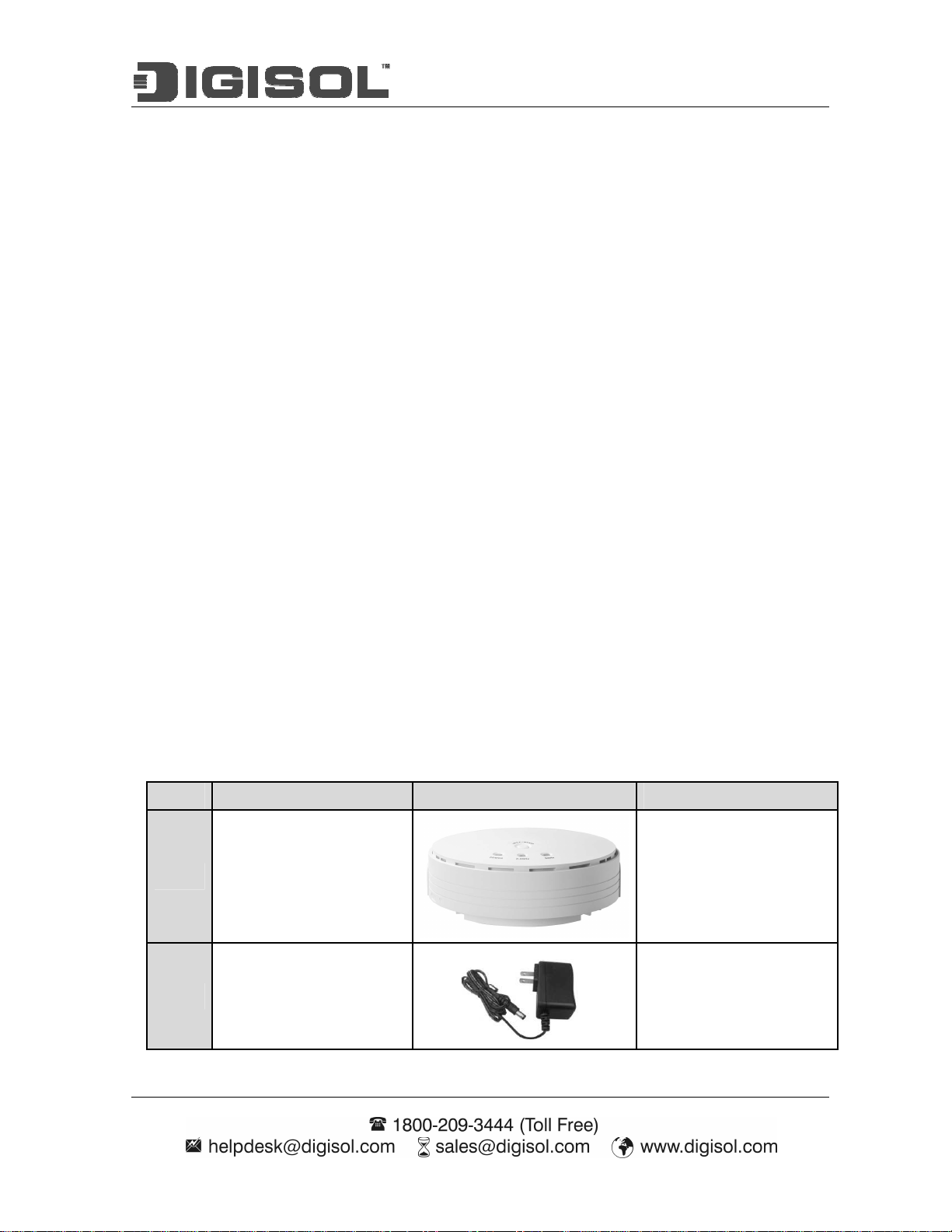
1.1 Package Contents
Before using this access point, please check if there is anything missing in the package, and
contact your dealer of purchase to claim for missing items:
• Ceiling Access Point
• DC 12V Power Adapter
• Patch Cord
• Installation Guide CD
Items Description Contents Quantity
1
2
WiFi 2.4G N300
Ceiling AP
Power Adapter
1 No.
1 No.
Page 7
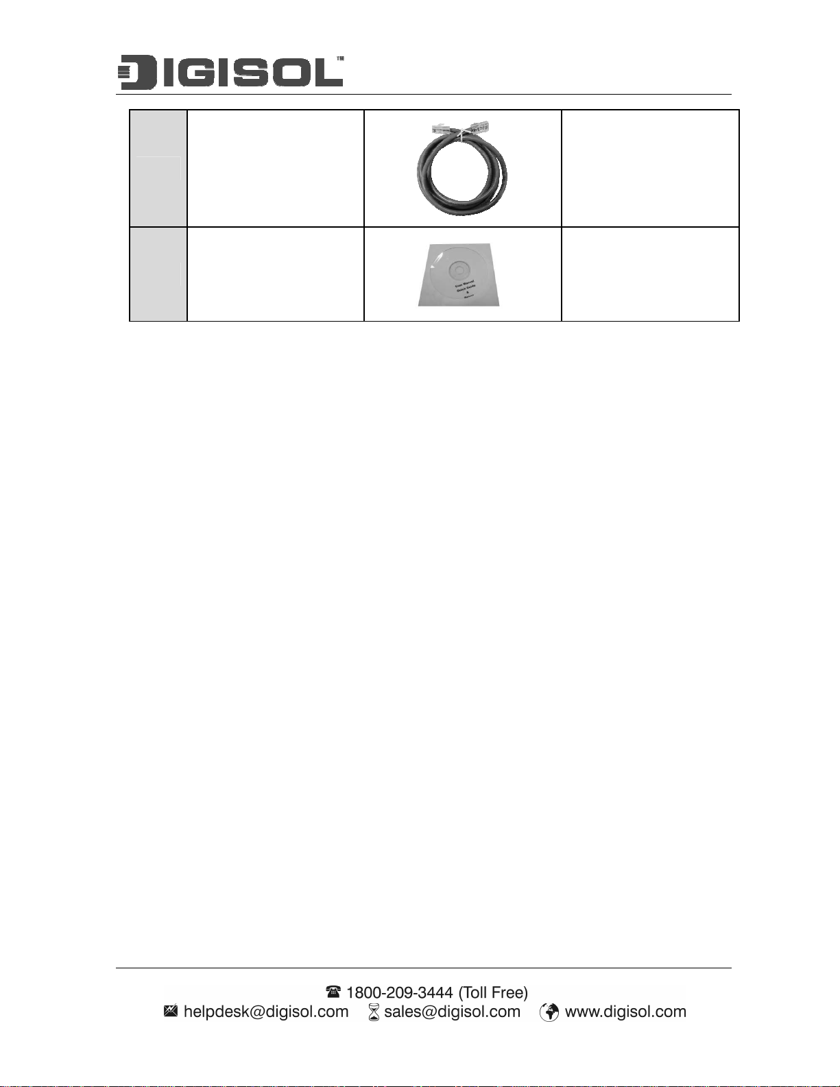
DG-WM2005SI User Manual
3 RJ45 Cable
4 Installation Guide CD
1 No.
1 No.
Page 8
DG-WM2005SI User Manual
1.2 Hardware Installation
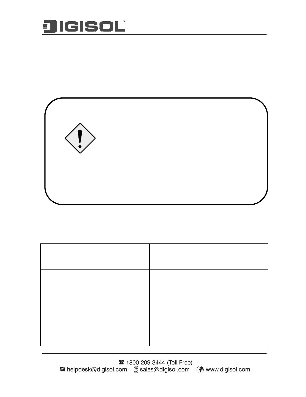
1.2.1 WARNING
Attention
Do not use the product in high humidity or high
temperatures.
Do not use the same power source for the Product as
other equipment. Only use the power adapter that comes
with the package. Using a different voltage rating power
adaptor may damage the device.
Do not open or repair the case yourself. If the Product is
too hot, turn off the power immediately and have it
repaired at a qualified service center.
Place the Product on a stable surface and avoid using this
product and all accessories outdoors.
1.2.2 SYSTEM REQUIREMENTS
•
Network Requirements
Web-based Configuration Utility
Requirements
An Ethernet-based Cable or DSL modem
•
IEEE 802.11n or 802.11b, g wireless clients
•
10/100 Ethernet
Computer with the following:
•
Windows®, Macintosh, or Linux-based
operating system
•
An installed Ethernet adapter
Browser Requirements:
•
Internet Explorer 6.0 or higher
•
Chrome 2.0 or higher
•
Firefox 3.0 or higher
•
Safari 3.0 or higher (with Java 1.3.1 or
Page 9

DG-WM2005SI User Manual
higher)
Windows® Users: Make sure you have the latest
version of Java installed. Visit www.java.com to
download the latest version.
CD Installation Wizard Requirements
Computer with the following:
•
Windows® 7, Vista®, or XP with Service
Pack 2
•
An installed Ethernet adapter
•
CD-ROM drive
Page 10
DG-WM2005SI User Manual
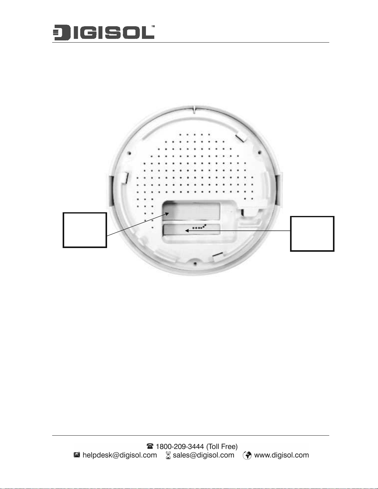
Adapter
Port
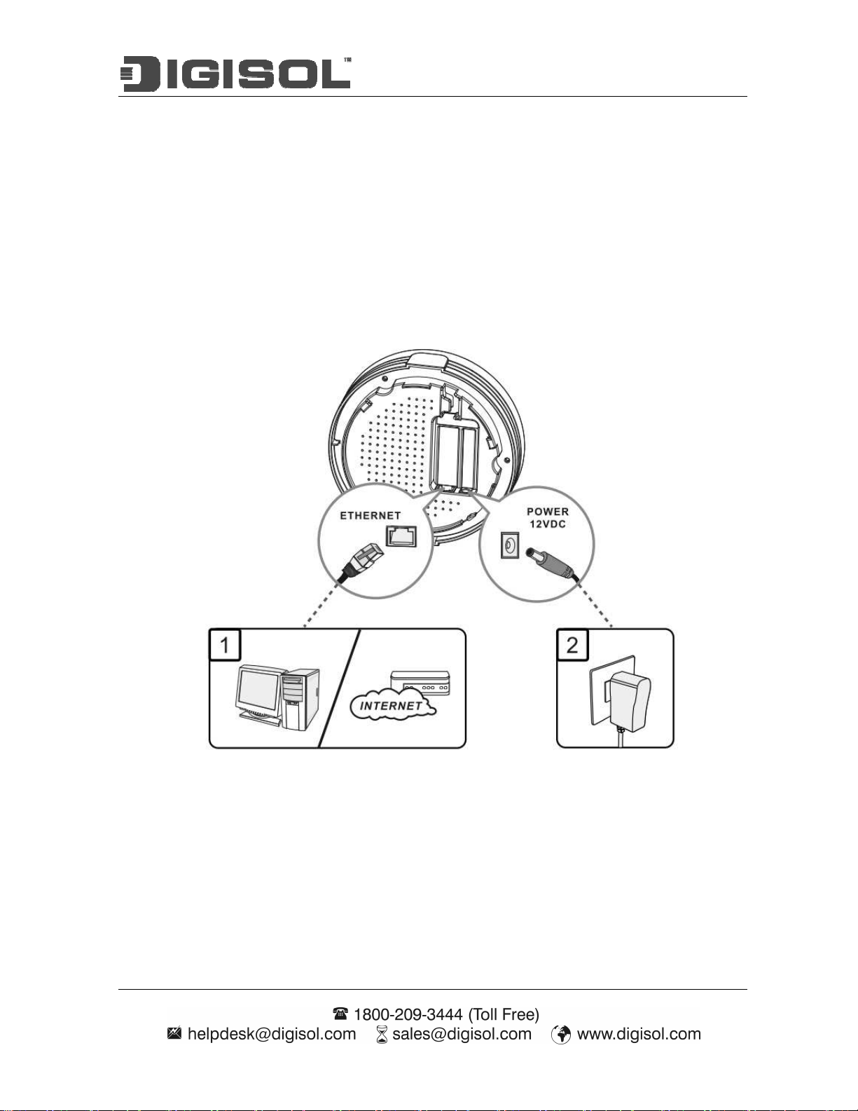
1.2.3 Hardware Configuration
Rear View:
PoE-PD
Ethernet
Receptor
for Power
Page 11
DG-WM2005SI User Manual
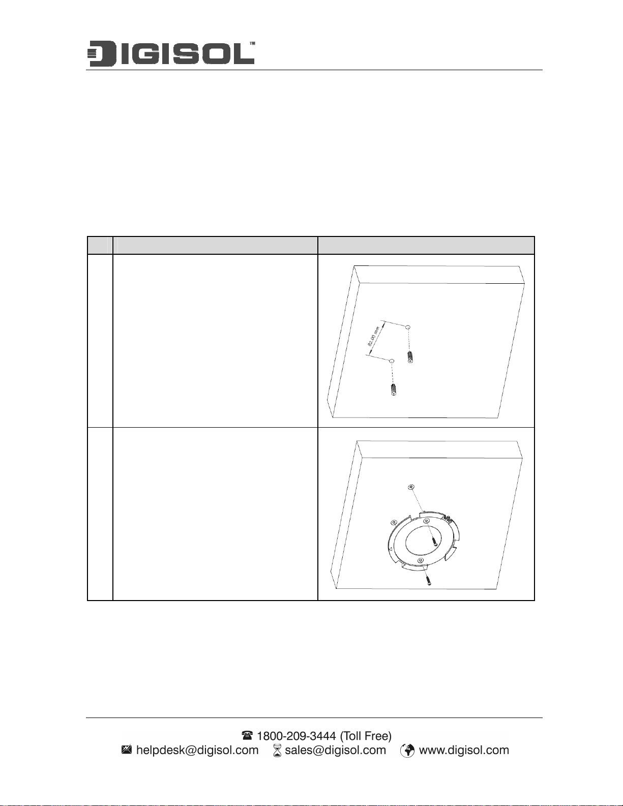
1.2.4 Mounting on the Ceiling / Wall
This device is designed for easily mounted on the ceiling or wall with a simple mount bracket.
Before mounting it to the expected location, please make proper configuration for the device
setting and run the PoE Ethernet cable to the location in advance.
The following illustrations show you how to mount this device on the ceiling / wall.
Description Illustration
Drill 2 holes for wall plugs.
A
Self-tapping screws (Diameter : 3mm)
If you run the cable above the ceiling
(invisible cabling), you have to drill
another big hole (about 10~20 mm
diameter) to pull out the cable for
connecting to the device.
Screw the mounting bracket on the ceiling
B
/ wall.
Page 12

DG-WM2005SI User Manual
Plug-in the cable (Ethernet cable, Power
C
cord) to the connectors in the button side.
Run the cables upward to proper location.
Attached this device to mounting bracket
D
by rotating it clock wisely to click into
place.
Installation completed.
E
Page 13
DG-WM2005SI User Manual
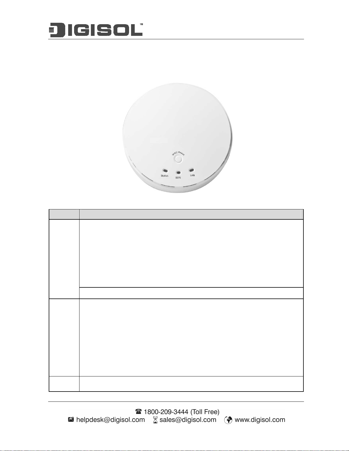
1.2.5 LED Indicators
LED Description
When the device is booted up and ready:
When WEC/Reset is triggered (with button pressed):
Status LED flashes at different rate according button-pressed duration.
Stage 1 (1 ~ 5 sec) : Flash very fast
Status
Stage 2 (6 ~ 10 sec) : Flash twice per second
Stage 3 (11~15 sec) : Flash once per second
Stage 4 (16~30 sec) : Solid Green
OFF: The device is powered off.
Green LED : Device is in Master Mode
Amber LED: Device is in Slave Mode
LED flash: data packet transferred.
LED in fast flash per second during 2min: WPS PBC status
WiFi
OFF: Wireless Radio is disabled.
LED in slow flash or Flash Green and Amber Alternately : Wireless
Connection doesn't establish.
LED in Solid: Wireless Connection established successfully.
LAN OFF: No Ethernet connection.
Page 14

DG-WM2005SI User Manual
Solid Green: Ethernet connection is linked up.
Flash Green: Data packet is transferred over the Ethernet link.
Page 15

DG-WM2005SI User Manual
1.2.6 Button Definition
There is one multi-function push button “WEC/Reset” in this device. According to different
button pressed duration, the device will take specific reaction. For ease of interacting with the
device, you can also check the Status and WiFi LED to determine when to release the button. The
Reset/WEC button’s behavior is defined below:
Function Button Description
There are two alternative AP modes defined for the
device to operate with WEC (Wireless Easy
Connection) feature. One is Master Mode (by default),
and the other is Slave Mode.
Please manually configure the Wireless Setting for the
Master AP through web UI first, and also prepare a
Slave AP that already been set to Slave Mode.
Press the WEC/Reset button of the Master AP for 1~3
seconds, release it to trigger the WEC process. Then,
WiFi Green LED flashes fast.
Press the WEC/Reset button of the Slave AP for 1~3
seconds, release it to trigger the WEC process. Then,
Easy Configuration
(Master to Slave)
WEC/Reset
(Press 3 sec)
WiFi Amber LED flashes fast.
Note: The Slave AP must be an un-configured one, if it
has already been paired and configured before, please
reset its Slave configuration first.
After a few seconds (normally about 30~60 seconds).
The Master and Slave APs can be paired automatically,
and auto-duplicates the VAP1 wireless setting of the
Master AP as that of the Slave AP.
(If there is something wrong during paring the two
devices, the process will be finished in 2 minutes.)
Once the easy configuration process completed, the
Status LED will be recovered to its original behavior
(prior to you triggered it). And the WiFi LED will be
Solid when Slave AP is connected to the network.
Page 16

DG-WM2005SI User Manual
Besides the above “Master to Slave” configuration,
the easy configuration process also supports “Slave to
Slave” configuration.
Press the WEC/Reset button of the first Slave AP (say
Slave1 that has been paired and configured) for 1~3
seconds, release it to trigger the WEC process. Then, the
WiFi LED flashes fast.
Press the WEC/Reset button of the second Slave AP
(say Slave2 that is an un-configured Slave AP) for 1~3
Easy Configuration
(Slave to Slave)
WEC/Reset
(Press 3 sec)
seconds, release it to trigger the WEC process. Then, the
WiFi LED flashes fast.
After a few seconds (normally about 30~60 seconds).
The Slave1 and Slave2 APs can be paired automatically,
and auto-duplicates the wireless setting of the Slave1 as
that of the Slave2.
(If there is something wrong during paring the two
devices, the process will be finished in 2 minutes.)
Once the easy configuration process completed, the
Status LED will be recovered to its original behavior
(prior to you triggered it).
AP Mode Toggling
There are two alternative AP modes defined for the
device to operate with WEC (Wireless Easy
Connection) feature. One is Master Mode (by default),
and the other is Slave Mode.
To change the AP mode from one to the other, you have
to:
Press the WEC/Reset button for 6~10 seconds, and then
WEC/Reset
release it.
(Press 8 sec)
The WiFi LED becomes OFF in 3 ~ 5 seconds,
After about 20 ~ 25 seconds, the WiFi LED will be lit
ON again to indicate that the AP Mode is changed.
It takes about 36 seconds to change (toggle) the AP
Mode completely.
WiFi Green LED : Device is in Master Mode
WiFi Amber LED: Device is in Slave Mode
Page 17

DG-WM2005SI User Manual
Press the WEC/Reset button for about 11~15 seconds
and release it.
Reset Slave AP
Configuration
WEC/Reset
(Press 13 sec)
The Slave AP will be marked as an un-configured
device, so that it can be paired with another Master or
configured Slave AP later.
For Master AP, there is no effect on this button behavior.
Press the Reset/WEC button for about 20 seconds till
the Status LED becomes solid Green to indicate that the
reset to default function is triggered. Release the button.
WEC/Reset
Reset to Default
Then, the device will reboot automatically and apply the
(Press 20 sec)
factory default settings as well.
It takes about 2 minutes to finish the reset to factory
default operation.
Page 18
DG-WM2005SI User Manual
2. Getting Started
Before you can install this product to designated location and make it operate properly, you have
to configure the device setting to fit in your network environment.
Hardware Preparation:
a. Connect an Ethernet cable between this device and the computer that you will operate to set
up the device.
b. Power on the device via connecting the power adaptor DC Plug to the DC Jack of this device
and plug in the power adaptor to an electrical outlet.
Software Preparation:
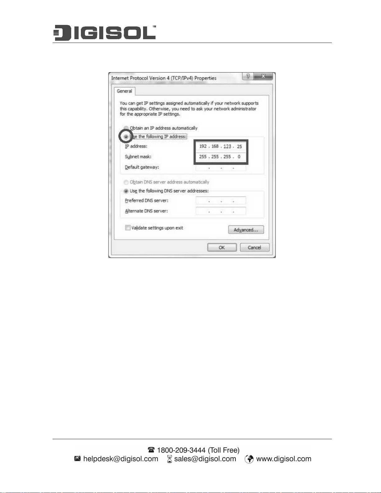
Most computers are connecting to a local network with dynamic IP (DHCP) setting. To access the
web UI of the device, you have to change your computer’s TCP/IPv4 settings into a static IP
setting for the Ethernet Interface. You can refer to Appendix A for how to assign a Static IP
address you your computer.
The device’s default IP address is 192.168.123.50, and your computer must be assigned with a
192.168.123.x IP address to get access to the device.
Page 19
DG-WM2005SI User Manual
Referring to Appendix A, and set the TCP/IPv4 address of your computer to 192.168.123.25,
and subnet mask to 255.255.255.0.
After applying this setting, you can now access to the web UI for configuring the device.
2.1 Easy Setup via Web UI
You can browse web UI to configure the device. Firstly you need to launch the Setup Wizard
browser first and then the Setup Wizard will guide you step-by-step to finish the basic setup
process.
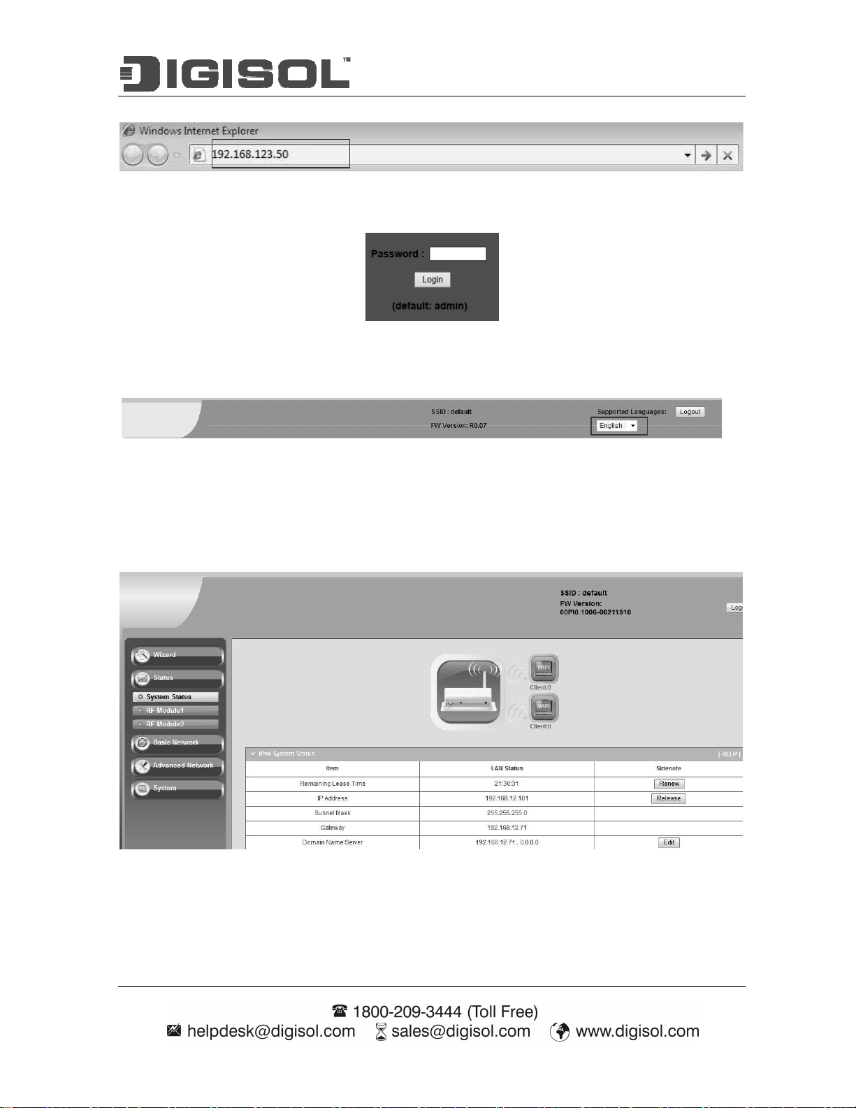
Activate the setup wizard:
Type in the IP Address (http://192.168.123.50)
Page 20
DG-WM2005SI User Manual
in the system authentication fields, and then click
Type the default password “admin”
‘login’ button.
Select your language.
Select “Wizard” for basic settings in a simple way.
Or, you can go to Basic Network / Advanced Network / Applications / System to setup the
configuration by your own selection.
Page 21
DG-WM2005SI User Manual
Press “Next” to start the Setup Wizard.
Configure with the Setup Wizard
Step 1
You can change the password of
administrator here.
Step 2
LAN IP Address.
You have to change the IP address of this
device according to your network
configuration.
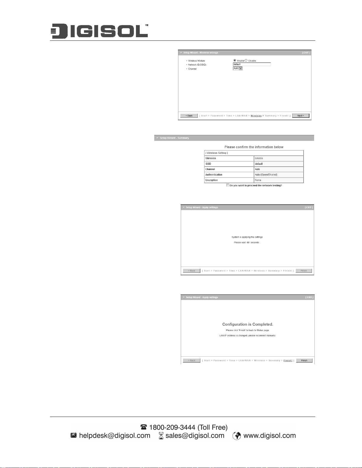
Step 3-1
Wireless settings.
You can specify the Wireless setting for
VAP1.
Step 3-2
Page 22
DG-WM2005SI User Manual
Wireless settings.
Specify VAP1’s wireless authentication and
encryption.
Step 4
Check the information again.
Step 5
System is applying the setting.
Step 6
Click finish to complete it.
Page 23
DG-WM2005SI User Manual
2.2 Use WEC Button to Setup Wireless Profiles
WEC (Wireless Easy Connection) is an easy configuration feature that is similar to well-known
WPS function. It can be used to duplicate one device’s wireless configuration to the other AP
devices from the same manufacture by clicking one button for both devices.
There are two alternative AP modes defined for the device to operate with WEC (Wireless Easy
Connection) feature. One is the Master Mode (by default), and the other is the Slave Mode. Before
starting to use WEC to configure your AP devices, you have to learn how to identify and set the
device in the Master Mode, or the Slave Mode (As stated in Section 1.2.4 and 1.2.5).
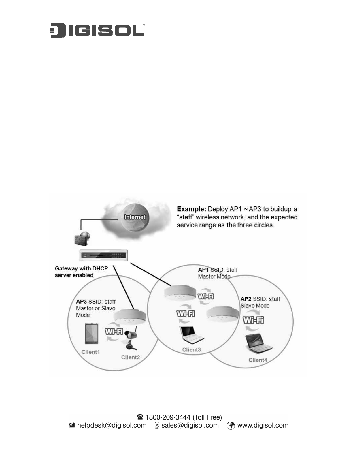
2.2.1 One Master and several isolated Slaves
As illustrated in above figure, how to configure the three APs (AP1, AP2, AP3) to build up the “
staff” wireless network? You can follow the procedure bellow:
Page 24

DG-WM2005SI User Manual
Step Button Description
1. Make sure AP1 is in Master Mode (WiFi LED
should be “Green” color, if not, you have to
1
2
3
4
Set AP1 in Master Mode,
and configure it via web UI.
Set AP2 and AP3 in Slave
Mode.
Easy configure AP2 via
WEC.
Easy configure AP3 via
WEC.
toggle its AP mode via pressing the WEC button for
9~10 seconds)
2. Login in to AP1 web UI and configure the wireless
settings as what you want (LAN IP, SSID, encryption
key, etc.).
1. Make sure AP2 / AP3 is in Slave Mode (WiFi LED
should be “Amber” color, if not, you have to
toggle its AP mode via pressing the WEC button for
9~10 seconds)
Master to Slave WEC:
1. Trigger AP1 into WEC configuration process via
pressing the WEC button for 3 second.
2. Trigger AP2 into WEC configuration process via
pressing the WEC button for 3 second.
3. It takes 30 ~ 60 seconds for the device to finish the
WEC configuration process.
Master to Slave WEC:
1. Trigger AP1 into WEC configuration process via
pressing the WEC button for 3 second.
2. Trigger AP3 into WEC configuration process via
pressing the WEC button for 3 second.
3. It takes 30 ~ 60 seconds for the device to finish the
WEC configuration process.
Mount the devices AP1,
5
AP2, and AP3 to expected
locations.
1. Install AP1 to its location first and verify its wireless
network connectivity with a client device (Client3).
2. Install AP2 to its location and verify its wireless
network connectivity with a client device (Client4)
at the location beyond the service range of AP1.
Besides, You can also check the AP2’s WiFi LED, it
should be “Solid Amber” if AP2 already connected a
Page 25

DG-WM2005SI User Manual
Master AP AP1.
3. Install AP3 to its location and verify its wireless
network connectivity with a client device (Client1)
at the location beyond the service range of AP1.
In this case, AP3 is located out of the service range
of AP1, you don’t have to check AP3’s WiFi LED,
but you have to connect the AP3 with an Ethernet
cable to the gateway.
2.2.2 One Master and a series of connected Slaves
This device also support universal repeater function, you can easily extend the wireless network
with a series repeaters that are wireless concatenated to build up the wireless network without
running Ethernet cables to each repeater.
As illustrated in above figure, if you intend to deploy 4 APs (AP1 ~ AP4) to create a “Staff”
wireless network, you can follow the procedure below:
Page 26

DG-WM2005SI User Manual
Make sure AP1 is in Master Mode (WiFi LED should be
Step Button Description
“Green” color, if not, you have to toggle its AP
1
2
3
4
Set AP1 in Master Mode,
and configure it via web UI.
Set AP2, AP3, AP4 in Slave
Mode.
Easy configure AP2 via
WEC.
Easy configure AP3 via
WEC.
mode via pressing the WEC button for 8 seconds)
Login in to AP1 web UI and configure the wireless
settings as what you want (LAN IP, SSID, encryption
key, etc..).
Make sure AP2 / AP3 / AP4 is in Slave Mode (WiFi
LED should be “Amber” color, if not, you have to
toggle its AP mode via pressing the WEC button for 8
seconds)
Master to Slave WEC:
Trigger AP1 into WEC configuration process via
pressing the WEC button for 3 second.
Trigger AP2 into WEC configuration process via
pressing the WEC button for 3 second.
It takes 30 ~ 60 seconds for the device to finish the
WEC configuration process.
Slave to Slave WEC:
Trigger AP2 into WEC configuration process via
pressing the WEC button for 3 second.
Trigger AP3 into WEC configuration process via
pressing the WEC button for 3 second.
It takes 30 ~ 60 seconds for the device to finish the
WEC configuration process.
5
Easy configure AP4 via
WEC.
Mount the devices AP1,
6
AP2, AP3, and AP4 to
Slave to Slave WEC:
Trigger AP3 into WEC configuration process via
pressing the WEC button for 3 second.
Trigger AP4 into WEC configuration process via
pressing the WEC button for 3 second.
It takes 30 ~ 60 seconds for the device to finish the
WEC configuration process.
Install AP1 to its location first and verify its wireless
network connectivity with a client device.
Page 27

DG-WM2005SI User Manual
expected locations. Install AP2 to its location and verify its wireless
network connectivity with a client device at the location
beyond the service range of AP1.
Besides, You can also check the AP2’s WiFi LED, it
should be “Solid Amber” if AP2 already connected
a Master AP AP1.
Install AP3 to its location and verify its wireless
network connectivity with a client device at the location
beyond the service range of AP2.
Besides, You can also check the AP3’s WiFi LED, it
should be “Solid Amber” if AP3 already connected
AP2.
Install AP4 to its location and verify its wireless
network connectivity with a client device at the location
beyond the service range of AP3.
Besides, You can also check the AP4’s WiFi LED, it
should be “Solid Amber” if AP4 already connected
AP3.
Although such wireless repeater function is available, there are limitations for such topology.
First, the available bandwidth for AP2 ~ AP4 will be decayed due to it is connected to it peer AP
wirelessly. It depends on the data rate and environment. Besides, if one of the AP, say AP2, is
disconnected, the APs behind it will be disconnected as well. Such topology needs more
maintenance effort to keep the whole wireless network connectivity.
If Ethernet cable is reachable, connecting each AP to an Ethernet Uplink is recommended. Above
WEC configuration process is also suitable for running Ethernet cables to AP2 ~ AP4 to get a
better wireless network..
Page 28

DG-WM2005SI User Manual
3 Making Configurations
Whenever you want to configure your network or this device, you can access the Configuration
Menu by opening the web-browser and typing in the IP Address of the device. The default IP
Address is: 192.168.123.50. In the configuration section you may want to check the connection
status of this device, to do Basic or Advanced Network setup or to check the system status. These
task buttons can be easily found in the cover page of the UI (User Interface).
Enter the default username and password “admin” in the System Password and then click
‘login’ button.
Afterwards, you can go Wizard, Basic Network, Advanced Network, Application or System
respectively on left hand side of web page.
Page 29

DG-WM2005SI User Manual
Note: You can see the Connection Status screen below after you logged in.
Note : You can see all the status of this device in the ‘‘‘‘Status’’’’ main menu section.
Page 30

DG-WM2005SI User Manual
3.1 Basic Network
You can enter Basic Network for Ethernet LAN, Wireless and IPv6 settings in this web page.
3.1.1 Ethernet LAN
Page 31

DG-WM2005SI User Manual
1. Device Network Type: This device supports two network types for connecting to your local
network.
Static IP: Allow a device to act as a Static host. If you need Static host and please entry IP
Address.
DHCP: Allow a device to act as a host requesting configuration parameters, such as an IP
address from a DHCP server.
Note: Please check if there is DHCP server in your Network, first.
2. LAN IP Address, Subnet Mask, Gateway, Primary / Secondary DNS: If you selected the
Static IP network type for this device, you have to further specify the LAN IP Address, Subnet
mask, Gateway, and optional Primary / Secondary DNS settings for well connecting to your
local network.
3.1.2 Wireless
Wireless settings allow you to set the WLAN (wireless LAN) configuration items. When the
wireless configuration is done, your wireless network is ready for supporting your local WiFi
devices such as your laptop PC, wireless printer and some portable devices.
Page 32

DG-WM2005SI User Manual
The embedded RF Module1/Wireless is a IEEE 802.11b/g/n compliant 2.4GHz Wireless Module.
3.1.2.1 Wireless Setup
There are several wireless operation modes provided by this device. They are: “AP Only
Mode”, “WDS Hybrid Mode”, “WDS Only Mode”, and “Universal Repeater Mode”. You
can choose the expected mode and configure the device manually.
Besides manually configuration the devices to be deployed one by one, you can also
configure your devices via the simple WEC configuration approach as stated in last Chapter.
By default, the Master AP is set to the WDS-hybrid Mode, and the Slave APs are set to the
Universal Repeater mode. You just have to manually configure the Master AP via the web UI
configuration, and use the WEC process for the rest Slave APs.
3.1.2.1.1 AP Only Mode
When acting as an access point, this device connects all the wireless stations to a wired
network.
Page 33

DG-WM2005SI User Manual
1. Wireless Module: Enable the wireless function.
2. Wireless Operation Mode: Choose “AP Only Mode” from the list.
3. Green AP: Enable the Green AP function to reduce the power consumption when there is
no wireless traffic.
4. AP Number: This device supports up to 8 SSIDs at the same time for you to manage
your wireless networks. You can select AP1 ~ AP8 and configure each wireless network
individually.
5. Network ID (SSID): Network ID is used for identifying a Wireless LAN. Client
stations can roam freely over this device and other Access Points that have the same
Network ID. The factory default SSID is “default”, you can change it to a meaningful
identifier for the wireless users to easy find it out.
6. SSID Broadcast: By default, the SSID Broadcast setting is “Enable”, and the device
will broadcast beacons that have some information, including SSID, to the air, so that
wireless clients can know how many AP devices by scanning the network. Therefore, if
this setting is configured as “Disable”, you can hide the wireless network from been
Page 34

DG-WM2005SI User Manual
scanned by wireless clients. Those who know the SSID can manually specify the SSID
on their client device to connect the hidden wireless network.
7. VLAN ID: This device supports mapping of a SSID to a certain VLAN ID to separate
workgroups across wireless and wired domains. By default, it is not enables. If you
enabled this function, you have to specify a VLAN ID for the wireless network.
8. Max Supported Stations: You can specify the number of maximum stations that can
associate to the SSID simultaneously.
9. Channel: The radio channel number. The permissible channels depend on the
Regulatory Domain. The factory default setting is auto channel selection. It’s
recommended to choose a channel that is not used in your environment to reduce radio
interference
10. Wireless Mode: The RF1 module supports 802.11b/g/n modes. You can also choose “N
only”, “G/N mixed” or “B/G/N mixed”. The factory default setting is “B/G/N mixed”.
11. Bandwidth: The default setting for Bandwidth is “Auto”. You can change it to
“20MHz” with care if some clients are suffering from the connectivity problem in higher
bandwidth setting.
12. Authentication & Encryption: You may select one of the following authentications to
secure your wireless network: Open (include 802.1x), Shared, Auto, WPA-PSK, WPA,
WPA2-PSK, WPA2, WPA-PSK/WPA2-PSK, or WPA /WPA2.
Open
Open system authentication simply consists of two communications. The first is an
authentication request by the client that contains the station ID (typically the MAC
address). This is followed by an authentication response from the AP containing a
success or failure message. An example of when a failure may occur is if the client's
MAC address is explicitly excluded in the AP’s configuration.
In this mode you can also enable the 802.1x feature if you have another RADIUS
server for user authentication. You need to input IP address, port, shared key of
RADIUS server here.
Page 35

DG-WM2005SI User Manual
In this mode, you can only choose “None” or “WEP” in the encryption field.
Shared
Shared key authentication relies on the fact that both stations taking part in the
authentication process have the same "shared" key or passphrase. The shared key is
manually set on both the client station and the AP. Three types of shared key
authentication are available today for home or small office WLAN environments.
Auto
The gateway will select appropriate authentication method (Open or Shared)
according to the WiFi client’s request automatically.
WPA-PSK
Select Encryption mode and enter the Pre-share Key. You can fill in 64 hexadecimal
(0, 1, 2…8, 9, A, B…F) digits, or 8 to 63 ASCII characters as the pre-share key.
WPA
Select Encryption mode and enter RADIUS Server related information. You have to
specify the IP address, and port number for the RADIUS Server, and then fill in 64
hexadecimal (0, 1, 2…8, 9, A, B…F) digits, or 8 to 63 ASCII characters as the shared
key. The key value is shared by the RADIUS server and this router. This key value
must be consistent with the key value in the RADIUS server. The available encryption
modes are “TKIP”, “AES”, or “TKIP/AES”.
WPA2-PSK
Select Encryption mode and enter the Pre-share Key. You can fill in 64 hexadecimal
(0, 1, 2…8, 9, A, B…F) digits, or 8 to 63 ASCII characters as the pre-share key.
WPA2
Select Encryption mode and enter RADIUS Server related information. You have to
specify the IP address, and port number for the RADIUS Server, and then fill in 64
hexadecimal (0, 1, 2…8, 9, A, B…F) digits, or 8 to 63 ASCII characters as the shared
key. The key value is shared by the RADIUS server and this router. This key value
must be consistent with the key value in the RADIUS server. The available encryption
modes are “TKIP”, “AES”, or “TKIP/AES”.
WPA-PSK/WPA2-PSK
Select Encryption mode and enter the Pre-share Key. You can fill in 64 hexadecimal
(0, 1, 2…8, 9, A, B…F) digits, or 8 to 63 ASCII characters as the pre-share key.
WPA/WPA2
If some of wireless clients can only support WPA, but most of them can support
WPA2. You can choose this option to support both of them. Select Encryption mode
and enter RADIUS Server related information. You have to specify the IP address,
Page 36

DG-WM2005SI User Manual
and port number for the RADIUS Server, and then fill in 64 hexadecimal (0, 1, 2…8,
9, A, B…F) digits, or 8 to 63 ASCII characters as the shared key. The key value is
shared by the RADIUS server and this router. This key value must be consistent with
the key value in the RADIUS server.
Afterwards, click on “Save” to store your settings or click “Undo” to give up the changes.
3.1.2.1.2 WDS Hybrid Mode
This mode makes device act as a wireless bridge but also have AP function. While acting as a
wireless Bridge, Wireless Router 1 and Wireless Router 2 can communicate with each other
through wireless interface (with WDS). Thus All Stations can communicate each other and
are able to access Internet if Wireless Router 1 has the Internet connection.
Page 37

DG-WM2005SI User Manual
1. Lazy Mode: This device support the Lazy Mode to automatically learn the MAC address
of WDS peers, you don’t have to input other peer AP's MAC address. However, not all
the APs can be set to enable the Lazy mode simultaneously; at least there must be one AP
with all the WDS peers’ MAC address filled.
2. Green AP: Enable the Green AP function to reduce the power consumption when there is
no wireless traffic.
3. AP Number: This device supports up to 8 SSIDs at the same time for you to manage
your wireless networks. You can select AP1 ~ AP8 and configure each wireless network
individually.
4. Network ID (SSID): Network ID is used for identifying a Wireless LAN. Client stations
can roam freely over this device and other Access Points that have the same Network ID.
The factory default SSID is “default”, you can change it to a meaningful identifier for the
wireless users to easy find it out.
5. SSID Broadcast: By default, the SSID Broadcast setting is “Enable”, and the device will
broadcast beacons that have some information, including SSID, to the air, so that wireless
Page 38

DG-WM2005SI User Manual
clients can know how many AP devices by scanning the network. Therefore, if this
setting is configured as “Disable”, you can hide the wireless network from been scanned
by wireless clients. Those who know the SSID can manually specify the SSID on their
client device to connect the hidden wireless network.
6. VLAN ID: This device supports mapping of a SSID to a certain VLAN ID to separate
workgroups across wireless and wired domains. By default, it is not enables. If you
enabled this function, you have to specify a VLAN ID for the wireless network.
7. Max Supported Stations: You can specify the number of maximum stations that can
associate to the SSID simultaneously.
8. Channel: The radio channel number. The permissible channels depend on the Regulatory
Domain. The factory default setting is auto channel selection. It’s recommended to
choose a channel that is not used in your environment to reduce radio interference
9. Wireless Mode: The RF1 module supports 802.11b/g/n modes. You can also choose “N
only”, “G/N mixed” or “B/G/N mixed”. The factory default setting is “B/G/N mixed”.
10. Bandwidth: The default setting for Bandwidth is “Auto”. You can change it to “20MHz”
with care if some clients are suffering from the connectivity problem in higher bandwidth
setting.
11. Authentication & Encryption: You may select one of the following authentications to
secure your wireless network: Open (include 802.1x), Shared, Auto, WPA-PSK, and
WPA2-PSK.
Open
Open system authentication simply consists of two communications. The first is an
authentication request by the client that contains the station ID (typically the MAC
address). This is followed by an authentication response from the AP containing a
success or failure message. An example of when a failure may occur is if the client's
MAC address is explicitly excluded in the AP’s configuration.
In this mode you can also enable the 802.1x feature if you have another RADIUS
server for user authentication. You need to input IP address, port, shared key of
RADIUS server here.
Page 39

DG-WM2005SI User Manual
In this mode, you can only choose “None” or “WEP” in the encryption field.
Shared
Shared key authentication relies on the fact that both stations taking part in the
authentication process have the same "shared" key or passphrase. The shared key is
manually set on both the client station and the AP. Three types of shared key
authentication are available today for home or small office WLAN environments.
Auto
The gateway will select appropriate authentication method (Open or Shared)
according to the WiFi client’s request automatically.
WPA-PSK
Select Encryption mode and enter the Pre-share Key. You can fill in 64 hexadecimal
(0, 1, 2…8, 9, A, B…F) digits, or 8 to 63 ASCII characters as the pre-share key.
WPA2-PSK
Select Encryption mode and enter the Pre-share Key. You can fill in 64 hexadecimal
(0, 1, 2…8, 9, A, B…F) digits, or 8 to 63 ASCII characters as the pre-share key.
12. Remote AP MAC 1 ~ Remote AP MAC 4: If you do not enable the Lazy mode, you
have to enter the wireless MAC address for each WDS peer one by one.
Afterwards, click on “Save” to store your settings or click “Undo” to give up the changes.
Page 40

DG-WM2005SI User Manual
3.1.2.1.3 WDS Only Mode
WDS (Wireless Distributed System) function let APs acts as a wireless LAN bridge. All
stations associated with WDS APs could see each other and roam through APs without
changing WiFi configurations. You can use this feature to build up a large wireless network in
a large space like airports, hotels and schools etc.
Page 41

DG-WM2005SI User Manual
1. Lazy Mode: This device support the Lazy Mode to automatically learn the MAC address
of WDS peers, you don’t have to input other peer AP's MAC address. However, not all
the APs can be set to enable the Lazy mode simultaneously; at least there must be one AP
with all the WDS peers’ MAC address filled.
2. Green AP: Enable the Green AP function to reduce the power consumption when there is
no wireless traffic.
3. Channel: The radio channel number. The permissible channels depend on the Regulatory
Domain. The factory default setting is auto channel selection. It’s recommended to
choose a channel that is not used in your environment to reduce radio interference
4. Wireless Mode: The RF1 module supports 802.11b/g/n modes. You can also choose “N
only”, “G/N mixed” or “B/G/N mixed”. The factory default setting is “B/G/N mixed”.
5. Bandwidth: The default setting for Bandwidth is “Auto”. You can change it to “20MHz”
with care if some clients are suffering from the connectivity problem in higher bandwidth
setting.
6. Authentication & Encryption: You may select one of the following authentications to
secure your wireless network: Open (include 802.1x), Shared, Auto, WPA-PSK, and
WPA2-PSK.
Open
Open system authentication simply consists of two communications. The first is an
Page 42

DG-WM2005SI User Manual
authentication request by the client that contains the station ID (typically the MAC
address). This is followed by an authentication response from the AP containing a
success or failure message. An example of when a failure may occur is if the client's
MAC address is explicitly excluded in the AP’s configuration.
In this mode you can also enable the 802.1x feature if you have another RADIUS
server for user authentication. You need to input IP address, port, shared key of
RADIUS server here.
In this mode, you can only choose “None” or “WEP” in the encryption field.
Shared
Shared key authentication relies on the fact that both stations taking part in the
authentication process have the same "shared" key or passphrase. The shared key is
manually set on both the client station and the AP. Three types of shared key
authentication are available today for home or small office WLAN environments.
Auto
The gateway will select appropriate authentication method (Open or Shared)
according to the WiFi client’s request automatically.
WPA-PSK
Select Encryption mode and enter the Pre-share Key. You can fill in 64 hexadecimal
(0, 1, 2…8, 9, A, B…F) digits, or 8 to 63 ASCII characters as the pre-share key.
WPA2-PSK
Select Encryption mode and enter the Pre-share Key. You can fill in 64 hexadecimal
(0, 1, 2…8, 9, A, B…F) digits, or 8 to 63 ASCII characters as the pre-share key.
7. Remote AP MAC 1 ~ Remote AP MAC 4: If you do not enable the Lazy mode, you
have to enter the wireless MAC address for each WDS peer one by one.
Afterwards, click on “Save” to store your settings or click “Undo” to give up the changes.
Page 43

DG-WM2005SI User Manual
3.1.2.1.4 Universal Repeater Mode
Universal Repeater is a technology used to extend wireless coverage. It provides the function
to act as Adapter (Client) and AP at the same time and can use this function to connect to a
Root AP and use AP (SSID name must be the same as that of Root AP) function to service all
wireless stations within its coverage. All the stations within the coverage of this access point
can be bridged to the Root AP.
Page 44

DG-WM2005SI User Manual
1. Green AP: Enable the Green AP function to reduce the power consumption when there is
no wireless traffic.
2. Network ID (SSID): Network ID is used for identifying a Wireless LAN. Client stations
can roam freely over this device and other Access Points that have the same Network ID.
The factory default SSID is “default”, you have to change it to the same SSID of the peer
AP to be associated under the Universal Repeater Mode.
3. Destination AP MAC: Besides to have the same SSID of the peer AP to be associated
under the Universal Repeater mode, you also have to specify the MAC address of the
peer AP to avoid making wrong connection with other AP that has the same SSID.
4. SSID Broadcast: By default, the SSID Broadcast setting is “Enable”, and the device will
broadcast beacons that have some information, including SSID, to the air, so that wireless
clients can know how many AP devices by scanning the network. Therefore, if this
setting is configured as “Disable”, you can hide the wireless network from been scanned
by wireless clients. Those who know the SSID can manually specify the SSID on their
client device to connect the hidden wireless network.
5. VLAN ID: This device supports mapping of a SSID to a certain VLAN ID to separate the
work groups across wireless and wired domains. By default, it is not enables. If you
enabled this function, you have to specify a VLAN ID for the wireless network.
6. Max Supported Stations: You can specify the number of maximum stations that can
associate to the SSID simultaneously.
7. Channel: The radio channel number. The permissible channels depend on the Regulatory
Domain. The factory default setting is auto channel selection. It’s recommended to
choose a channel that is not used in your environment to reduce radio interference
8. Bandwidth: The default setting for Bandwidth is “Auto”. You can change it to “20MHz”
with care if some clients are suffering from the connectivity problem in higher bandwidth
setting.
9. Authentication & Encryption: You may select one of the following authentications to
secure your wireless network: Open, Shared, Auto, WPA-PSK, and WPA2-PSK.
Afterwards, click on “Save” to store your settings or click “Undo” to give up the changes.
Page 45

DG-WM2005SI User Manual
3.1.3 Advanced Wireless Setup
This device provides advanced wireless setup for professional user to optimize the wireless
performance under the specific installation environment.
3.1.3.1 Advanced RF Module1/Wireless Settings
1. Beacon interval: Beacons are packets sent by a wireless router to synchronize wireless
devices.
2. Transmit Power: Normally the wireless transmission power operates at 100% out power
specification of this device. You can lower down the power ratio to prevent transmissions
from reaching beyond your corporate/home office or designated wireless area.
3. RTS Threshold: If an excessive number of wireless packet collision occurred, the
wireless performance will be affected. It can be improved by adjusting the RTS/CTS
(Request to Send/Clear to Send) threshold value.
4. Fragmentation: Wireless frames can be divided into smaller units (fragments) to
improve performance in the presence of RF interference and at the limits of RF coverage.
5. DTIM interval: A DTIM is a countdown informing clients of the next window for
listening to broadcast and multicast messages. When the wireless router has buffered
Page 46

DG-WM2005SI User Manual
broadcast or multicast messages for associated clients, it sends the next DTIM with a
DTIM Interval value.
6. WMM Capable: WMM can help control latency and jitter when transmitting multimedia
content over a wireless connection.
7. WLAN Partition: You can check the WLAN Partition function to separate the wireless
clients associated to the same VAP. The wireless clients can’t communicate each other,
but they can access the internet and other Ethernet LAN devices
8. AP Isolation: If you enabled multiple VAPs in this device, you can further decide
whether the wireless clients associated to different VAPs can access to each other or not.
When you enabled the AP Isolation function, Each VAP is isolated to the others
consequently.
9. TX Rate: For WiFi transmit rate, you can choose “Best” for auto-adjustment according to
WiFi signal quality in your environment, or you can fix it in certain TX rate. Please note
the WiFi connection may be dropped if you fix at a higher date rate but in a noisy (poor
RF signal quality) environment.
Afterwards, click on “Save” to store your settings or click “Undo” to give up the changes.
Page 47

DG-WM2005SI User Manual
3.1.4 IPv6
The growth of the Internet has created a need for more addresses than are possible with IPv4. IPv6
(Internet Protocol version 6) is a version of the Internet Protocol (IP) intended to succeed IPv4,
which is the protocol currently used to direct almost all Internet traffic. IPv6 also implements
additional features not present in IPv4. It simplifies aspects of address assignment (stateless
address auto-configuration), network renumbering and router announcements when changing
Internet connectivity providers.
This device supports IPv6, it works as a IPv6 bridge, you can use it to build a IPv6 network.
1. LAN IPv6 address settings: Please enter “LAN IPv6 address” and ignore the “LAN IPv6
Link-Local address”.
“2001:0db8:85a3:0000:0000:8a2e:0370:7334”
Page 48

DG-WM2005SI User Manual
3.2 Advanced Network
This device also supports other advanced network features for you to further manage the device.
You can finish the configuration for Firewall, and Management in this section.
Page 49

DG-WM2005SI User Manual
3.2.1 Firewall
3.2.1.1 MAC Address Control
MAC Address Control allows you to assign different access right for different users and to
assign a specific IP address to a certain MAC address.
1. MAC Address Control: Check “Enable” to enable the “MAC Address Control”. All of
the settings in this page will take effect only when “Enable” is checked.
2. Association control: Check "Association control" to enable the control of which wireless
client can associate to the wireless LAN. If a client is denied to associate to the wireless
LAN, it means the client can't send or receive any data via this device. Choose "allow" or
"deny" to allow or deny the clients, whose MAC addresses are not in the "Control table",
to associate to the wireless LAN.
Afterwards, click on “Save” to store your settings or click “Undo” to give up the changes.
Page 50

DG-WM2005SI User Manual
3.2.2 Management
3.2.2.1 UPNP
UPnP Internet Gateway Device (IGD) Standardized Device Control Protocol is a NAT port
mapping protocol and is supported by some Network device. It is a common communication
protocol of automatically configuring port forwarding. Applications using peer-to-peer
networks, multiplayer gaming, and remote assistance programs need a way to communicate
through home and business gateways. Without IGD one has to manually configure the
gateway to allow traffic through, a process which is error prone and time consuming
This device supports the UPnP Internet Gateway Device (IGD) feature. By default, it is
enabled.
Page 51

DG-WM2005SI User Manual
3.2.2.2 SNMP
In brief, SNMP, the Simple Network Management Protocol, is a protocol designed to give a
user the capability to remotely manage a computer network by polling and setting terminal
values and monitoring network events.
Page 52

DG-WM2005SI User Manual
1. Enable SNMP: Enable this Function.
2. SNMP Version: Supports SNMP V1, V2c, and V3.
3. Get Community: The community of GetRequest that this device will respond. This is a
text password mechanism that is used to weakly authenticate queries to agents of
managed network devices.
4. Set Community: The community of SetRequest that this device will accept.
5. SNMPv3 Settings: User 1/2: This device supports up to two SNMP management
accounts. You can specify the account permission as “Read” or “Read/Write”
respectively.
6. User 1/2 AUTH Mode: Select MD5 or SHA as the method of password encryption for
the specified level of access, or to disable authentication.
7. User 1/2 Privacy Mode: You can configure the SNMP privacy mode. There are three
modes for you to choose: “noAuthNoPriv” for both authentication and private key are not
required, “authNoPriv” for no private key required, and “authPriv” for both
authentication and private key required.
8. Username 1/2: Use this field to identify the user name for the specified level of access.
9. Password 1/2: Use this field to set the password for the specified level of access.
10. User 1/2 Priv Key: Use this field to define the encryption key for the specified level of
access.
11. IP (Trap Event Receiver) 1 ~ 4: Enter the IP addresses or Domain Name of your SNMP
Management PCs. You have to specify the IP address, so that the device can send SNMP
Page 53

DG-WM2005SI User Manual
Trap message to the management PCs consequently.
Afterwards, click on “Save” to store your settings or click “Undo” to give up the changes.
3.3 System
In this section you can see system information, system logs, use system tools for system update
and do service scheduling and system administration setting.
Page 54

DG-WM2005SI User Manual
3.3.1 System Information
You can view the System Information in this page.
3.3.2 System Status
3.3.2.1 Web Log
1. Log Types: You can select the log types to be collected in the web log area. There are
“System”, “Attacks”, “Drop”, and “Debug” types for you to select.
2. Web Log: You can browse, refresh, download, and clear the log messages.
Page 55

DG-WM2005SI User Manual
3.3.2.2 Syslog
This device also can export system logs to specific destination by means of syslog (UDP) and
SMTP(TCP). With enabled Syslog function, this device will send log to a certain host
periodically. You need to install a syslog utility on a host to receive syslogs.
The items you have to setup include:
1. IP Address for syslogd: Host IP of destination where syslog will be sent to. Check
Enable to enable this function.
3.3.2.3 Email Alert
Page 56

DG-WM2005SI User Manual
This device can also export system logs via sending emails to specific recipients. The items
you have to setup include:
1. Setting of Email alert: Check if you want to enable Email alert (send syslog via email).
2. SMTP Server: Port: Input the SMTP server IP and port, which are connected with ':'. If
you do not specify port number, the default value is 25.
For example, "mail.your_url.com" or "192.168.1.100:26".
3. SMTP Username: Enter the Username offered by your ISP.
4. SMTP Password: Enter the password offered by your ISP.
5. E-mail Addresses: The recipients are the ones who will receive these logs. You can
assign more than 1 recipient, using ';' or ',' to separate these email addresses.
6. E-mail Subject: The subject of email alert is optional.
Afterwards, click on “Save” to store your settings or click “Undo” to give up the changes.
3.3.3 System Tools
3.3.3.1 Change Password
You can change the System Password here. We strongly recommend you to change the
system password for security reason. Click on “Save” to store your settings or click “Undo”
to give up the changes.
Page 57

DG-WM2005SI User Manual
3.3.3.2 FW Upgrade
If new firmware is available, you can upgrade device firmware through the WEB GUI here
Press “browse” button to indicate the file name of new firmware, and then press Upgrade
button to start to upgrade new firmware on this device. If you want to upgrade a firmware
which is from GPL policy, please check “Accept unofficial firmware”.
.
NOTE. PLEASE DO NOT TURN THE DEVICE OFF WHEN UPGRADE IS
PROCEEDING.
Page 58

DG-WM2005SI User Manual
3.3.3.3 System Time
If new firmware is available, you can upgrade device firmware through the WEB GUI here.
1. Time Zone: Select a time zone where this device locates.
2. Auto-Synchronization: Check the “Enable” checkbox to enable this function. Besides,
you can select a NTP time server to consult UTC time.
3. Sync with Time Server: Click on the button if you want to set Date and Time by NTP
Protocol.
4. Sync with my PC: Click on the button if you want to set Date and Time using the PC’s
Date and Time.
Afterwards, click on “Save” to store your settings or click “Undo” to give up the changes.
Page 59

DG-WM2005SI User Manual
3.3.3.4 Others
In this section you can do system backup, reset to default, system reboot settings and ping
test.
1. Backup Setting: You can backup your settings by clicking the “Backup” button and
save it as a bin file. Once you want to restore these settings, please click Firmware
Upgrade button and use the bin file you saved.
2. Reset to Default: You can also reset this device to factory default settings by clicking
the “Reset“ button.
3. Reboot: You can also reboot this device by clicking the “Reboot“ button.
4. Domain Name or IP address for Ping Test: This allows you to configure an IP, and
ping the device. You can ping a specific IP to test whether it is alive.
5. Domain Name or IP address for Traceroute: Traceroute is a network diagnostic tool
for displaying the route (path) and measuring transit delays of packets across an IP
network. Traceroute proceeds unless all (three) sent packets are lost more than twice,
then the connection is lost and the route cannot be evaluated. Ping, on the other hand,
only computes the final round-trip times from the destination point
Page 60

DG-WM2005SI User Manual
3.3.4 MMI
3.3.4.1 Web UI
You can set UI administration time-out duration in this page. If the value is “0”, means the
time-out is unlimited.
Page 61

DG-WM2005SI User Manual
4 Troubleshooting
This Chapter provides solutions to problems for the installation and operation of the WiFi
Concurrent N300 Business AP. You can refer to the following if you are having problems.
1 Why can’t I configure the device even the cable is plugged and the LED is lit?
Do a Ping test to make sure that the WiFi
Access Point is responding.
Go to Start > Run.
1. Type cmd.
Note: It is recommended that you
2. Press OK.
3. Type ipconfig to get the IP of default gateway.
4. Type “ping 192.168.123.50”. Assure that you ping the correct IP Address assigned to
the WiFi Concurrent N300 Business AP. It will show four replies if you ping
correctly.
Ensure that your Ethernet Adapter is working, and that all network drivers are installed
Page 62

DG-WM2005SI User Manual
properly. Network adapter names will vary depending on your specific adapter. The
installation steps listed below are applicable for all network adapters.
1. Go to Start > Right click on “My Computer” > Properties.
2. Select the Hardware Tab.
3. Click Device Manager.
4. Double-click on “Network Adapters”.
5. Right-click on Wireless Card bus Adapter or your specific network adapter.
6. Select Properties to ensure that all drivers are installed properly.
7. Look under Device Status to see if the device is working properly.
8. Click “OK”.
2 What can I do if my Ethernet connection does not work properly?
A. Make sure the RJ45 cable connects with the device.
B. Ensure that the setting on your Network Interface Card adapter is “Enabled”.
C. If settings are correct, ensure that you are not using a crossover Ethernet cable, not all
Network Interface Cards are MDI/MDIX compatible, and use a patch cable is
recommended.
D. If the connection still doesn’t work properly, then you can reset it to default.
3 Something wrong with the wireless connection?
A. Can’t setup a wireless connection?
I. Ensure that the SSID and the encryption settings are exactly the same to the
Clients.
II. Move the WiFi Concurrent N300 Business AP and the wireless client into the same
room, and then test the wireless connection.
Page 63

DG-WM2005SI User Manual
III. Disable all security settings such as WEP, and MAC Address Control.
IV. Turn off the WiFi Concurrent N300 Business AP and the client, then restart it and
then turn on the client again.
V. Ensure that the LEDs are indicating normally. If not, make sure that the power and
Ethernet cables are firmly connected.
VI. Ensure that the IP Address, subnet mask, gateway and DNS settings are correctly
entered for the network.
VII. If you are using other wireless device, home security systems or ceiling fans, lights
in your home, your wireless connection may degrade dramatically. Keep your
product away from electrical devices that generate RF noise such as microwaves,
monitors, electric motors…
B. What can I do if my wireless client can not access the Internet?
I. Out of range: Put the device closer to your client.
II. Wrong SSID or Encryption Key: Check the SSID or Encryption setting.
III. Connect with wrong AP: Ensure that the client is connected with the correct Access
Point.
i. Right-click on the Local Area Connection icon in the taskbar.
ii. Select View Available Wireless Networks in Wireless Configure. Ensure you
have selected the correct available network.
iii. Reset the WiFi Concurrent N300 Business AP to default setting
C. Why does my wireless connection keep dropping?
I. Antenna Orientation.
i. Try different antenna orientations for the WiFi Concurrent N300 Business AP.
ii. Try to keep the antenna at least 6 inches away from the wall or other objects.
Page 64

DG-WM2005SI User Manual
II. Try changing the channel on the WiFi Concurrent N300 Business AP, and your
Access Point and Wireless adapter to a different channel to avoid interference.
III. Keep your product away from electrical devices that generate RF noise, like
microwaves, monitors, electric motors, etc.
4 What to do if I forgot my encryption key?
1. Go back to advanced setting to set up your Encryption key again.
2. Reset the WiFi Concurrent N300 Business AP to default setting
5 How to reset to default?
1. Ensure the WiFi Concurrent N300 Business AP is powered on
2. Find the Reset button on the right side
3. Press the Reset button for 8 seconds and then release.
4. After the WiFi Concurrent N300 Business AP reboots, it has back to the factory default
settings.
Page 65

DG-WM2005SI User Manual
Appendix A. Assigning a Static IP in Windows PC
When organizing your local network it’s easier to assign each computer it’s own IP address than
using DHCP. Here we will take a look at doing it in XP, Windows 7, Windows 8 and Windows
8.1.
If you have a home network with several computes and devices, it’s a good idea to assign each of
them a specific address. If you use DHCP (Dynamic Host Configuration Protocol), each computer
will request and be assigned an address every time it’s booted up. When you have to do
troubleshooting on your network, it’s annoying going to each machine to figure out what IP they
have.
Using Static IPs prevents address conflicts between devices and allows you to manage them more
easily. Assigning IPs to Windows is essentially the same process, but getting to where you need to
be varies between each version.
Windows 7 or Windows 8.x
To change the computer’s IP address in Windows 7, type network and sharing into the Search box
in the Start Menu and select Network and Sharing Center when it comes up. If you are in
Windows 8.x it will be on the Start Screen itself, like the screenshot at the top of this article.
Page 66

DG-WM2005SI User Manual
Then when the Network and Sharing Center opens, click on Change adapter settings. This will be
the same on Windows 7 or 8.x.
Page 67

DG-WM2005SI User Manual
Right-click on your local adapter and select Properties.
In the Local Area Connection Properties window highlight Internet Protocol Version 4 (TCP/IPv4)
then click the Properties button.
Page 68

DG-WM2005SI User Manual
Now select the radio button Use the following IP address and enter in the correct IP, Subnet mask,
and Default gateway that corresponds with your network setup. Then enter your Preferred and
Alternate DNS server addresses. Here we’re on a home network and using a simple Class C
network configuration and Google DNS.
Check Validate settings upon exit so Windows can find any problems with the addresses you
entered. When you’re finished click OK.
Page 69

DG-WM2005SI User Manual
Now close out of the Local Area Connections Properties window.
Page 70

DG-WM2005SI User Manual
Windows 7 will run network diagnostics and verify the connection is good. Here we had no
problems with it, but if you did, you could run the network troubleshooting wizard.
Now you can open the command prompt and do an ipconfig to see the network adapter settings
have been successfully changed.
Windows XP
In this example we’re using XP SP3 Media Center Edition and changing the IP address of the
Wireless adapter.
To set a Static IP in XP right-click on My Network Places and select Properties.
Page 71

DG-WM2005SI User Manual
Right-click on the adapter you want to set the IP for and select Properties.
Highlight Internet Protocol (TCP/IP) and click the Properties button.
Page 72

DG-WM2005SI User Manual
Now change the IP, Subnet mask, Default Gateway, and DNS Server Addresses. When you’re
finished click OK.
Page 73

DG-WM2005SI User Manual
You will need to close out of the Network Connection Properties screen before the changes go
into effect.
Page 74

DG-WM2005SI User Manual
Again you can verify the settings by doing an ipconfig in the command prompt. In case you’re not
sure how to do this, click on Start then Run.
In the Run box type in cmd and click OK.
Page 75

DG-WM2005SI User Manual
Then at the prompt type in ipconfig and hit Enter. This will show the IP address for the network
adapter you changed.
If you have a small office or home network, assigning each computer a specific IP address makes
it a lot easier to manage and troubleshoot network connection problems.
[Source: How to Assign a Static IP Address in Windows 7, 8, XP, or Vista;
http://www.howtogeek.com/howto/19249/how-to-assign-a-static-ip-address-in-xp-vista-or-windo
ws-7/]
Warranty Information
Please refer www.digisol.com for warranty information in your region.
 Loading...