

Page 1

1
Network Video Recorder
DG-SR4508 User Manual
V1.0
2018-02-14
As our products undergo continuous development the specifications are subject to change without prior notice.
___________________________________________________________________________________________
________
Page 2

NVR User Manual
2
1.
Product Introduction......................................................................................................................... 4
2.
Open-package check and cable connections..................................................................................... 5
2-1 Package Contents..................................................................................................................... 5
2-2 Front panel and rear panel.........................................................................................................5
2-3 Hard disk installation................................................................................................................6
2-4 Front panel................................................................................................................................7
2-5 Rear panel.................................................................................................................................7
2-6 Audio and video input and output connections........................................................................ 8
2-6-1 Video output connections and options............................................................................8
2-6-2 Audio signal input...........................................................................................................8
2-6-3 Audio signal output.........................................................................................................8
3
Basic operation...................................................................................................................................9
3-1 Turn on..................................................................................................................................... 9
3-2 Turn off.....................................................................................................................................9
3-3 NVR Configuration..................................................................................................................10
INDEX
1-1 Introduction and safety information........................................................................................ 4
3-3-1 Start-Up Wizard.............................................................................................................11
3-3-1-a) Mouse Operation....................................................................................................... 12
3-3-1-b) Input Method.............................................................................................................12
3-3-1-c) Navigation Bar……………………………………………………………………13
3-3-2 Main menu........................................................................................................................ 14
3-3-2-1 Data Inquiry & Replay.............................................................................................19
Inquire By Time…………………………………………………………………19
Intel Play................................................................................................................. 20
Data Management……………………………………………………………21
3-3-2-2 Backup Management................................................................................................23
Instant Backup.........................................................................................................24
Manual Backup....................................................................................................... 24
Backup file Display.................................................................................................25
Scheduled Backup...................................................................................................25
3-3-2-3 Video Settings.......................................................................................................... 26
Recording Parameters............................................................................................. 26
Page 3

NVR User Manual
3
Manual Recording............................................................................................... 27
Scheduled Recording.......................................................................................... 28
3-3-2-4 Alarm Settings…………………………………………………………………29
Motion Detect..................................................................................................... 29
Sensor Alarm.......................................................................................................30
Alarm Output...................................................................................................... 31
Other Alarms.......................................................................................................32
3-3-2-5 Channel Management.............................................................................................. 32
Add IP Cameras................................................................................................... 33
Deleting IP Cameras............................................................................................ 34
IPC Centralized Management.............................................................................. 35
3-3-2-6 Settings Management............................................................................................... 36
General Settings.................................................................................................. 37
Time Settings..................................................................................................... 39
Network Settings...............................................................................................44
3-3-2-7 HDD Management……………………………………………………………..50
3-3-2-8 System Information…………………………………………………………….54
3-3-2-9 System Maintenance……………………………………………………………58
4.0 Introduction to Web View………………………………………………………………….63
7 FAQ and maintenance........................................................................................................................ 65
7-1 FAQ................................................................................................................................................................65
Appendix 1. Hard disk capability calculatio....................................................................................... 69
Appendix 2. Technical Parameters………………………………………………………………..70
Page 4

NVR User Manual
4
1. Product Introduction
Please ensure the NVR level installation in a stable workplace.
Please install in ventilated place. Keep the vent clean.
Use within the rating input and output scope.
1-1 Introduction and safety information
Thank you for purchasing DIGISOL NVR!
This user manual is a reference guide for the installation and operation of your NVR. Before
installation and operation please read the following safeguards and warnings carefully!
Important Safeguards and Warnings
Do not place heavy objects on the NVR.
Do not let any solid or liquid fall into or infiltrate the NVR.
Please brush the printed circuit boards, connectors, fans, machine box and so on regularly.
Before the dust cleaning please switch off the power supply and unplug it.
Do not disassemble or repair the NVR yourself.
Do not replace the components yourself.
Environment
Please place and use the NVR between 0ºC and 40ºC. Avoid direct sunlight & keep the NVR
away from heat source.
Do not install the NVR in damp environment.
Do not use the NVR in smoky or dusty environment.
Avoid collision or strong fall.
Page 5

NVR User Manual
5
2. Open-package check and cable connections
One NVR (8 channel)
Power adapter
Quick Installation Guide
1 USB Mouse
Installation Guide CD
Tools Package (Screws)
2-1 Package Contents
Before you start using this NVR, please check if there’s anything missing in the package, and contact your
dealer of purchase to claim for missing items:
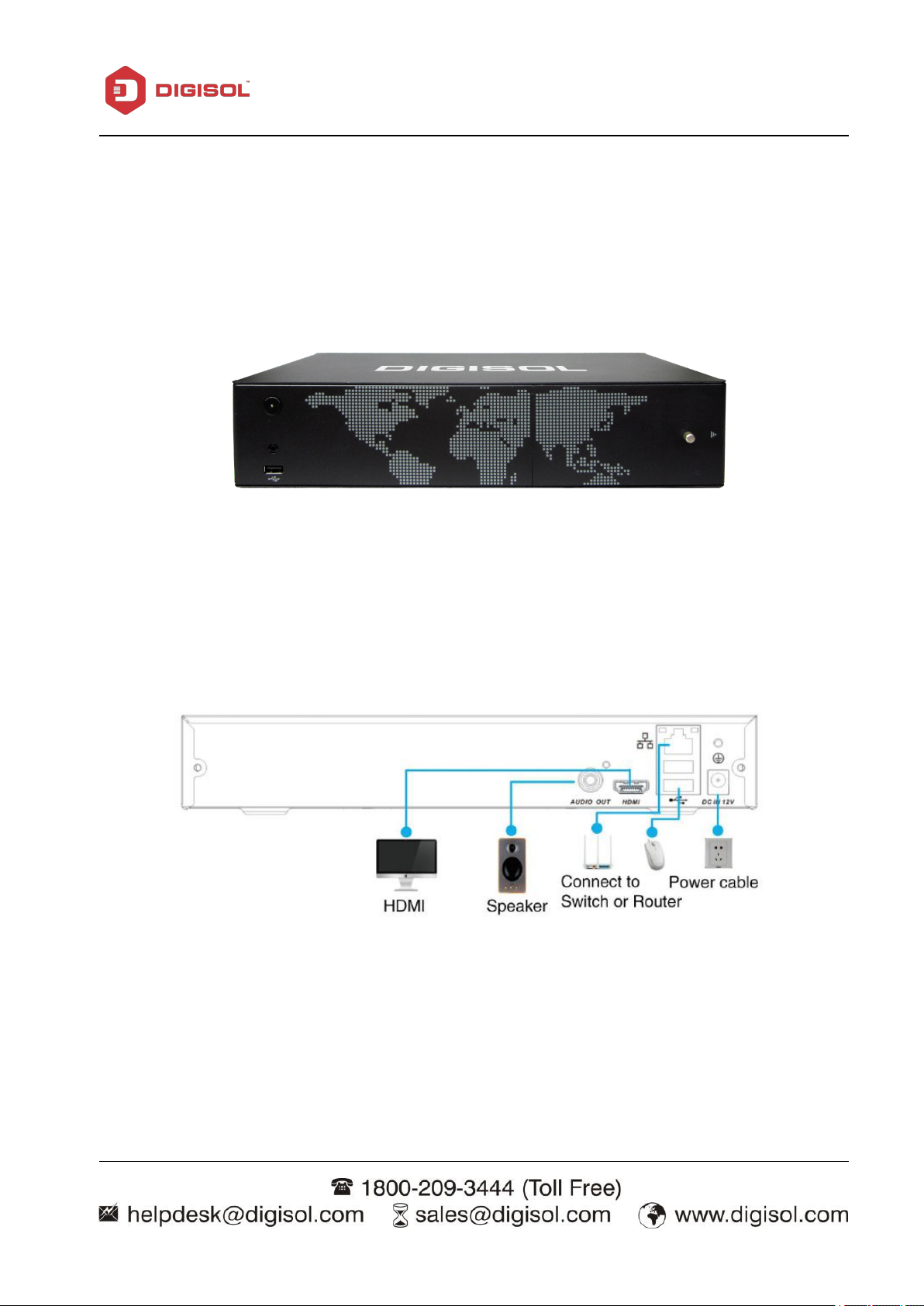
2-2 Front panel and rear panel
The key function specifications in the front panel and the interface specifications in the rear
panel are mentioned in Appendix 3.
Please check whether the product type in the front panel is according to the product type
you ordered.
The label in the rear panel is very important for the after service. Please protect it carefully. When
you contact us for after service, please provide the product type and serial number in the label.
Page 6
6
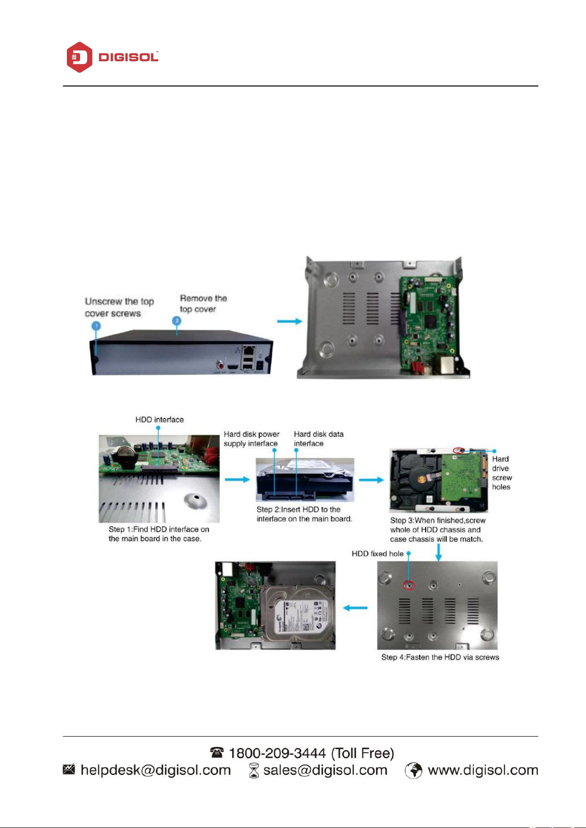
2-3 Hard disk installation
The NVR contain 2 SATA HDD. If installing or upgrading, please use a
HDD of 7200rpm or higher which is specially designed for NVR/ DVR applications.
Please follow the instructions mentioned below to installT/upgrade the HDD.
NOTE: The below shown product images are for illustration purpose only.
Actual product may vary.
NVR User Manual
Page 7
7
2-4 Front panel
NVR User Manual
2-5 Rear P anel
Page 8

NVR User Manual
8
2-6 Audio and video input and output connections
2-6.1 Video output connections and options
1.
Do not stay in the turn-on state for a long time.
2.
Keep the computer display normal working by demagnetizing regularly.
3.
Stay away from the electromagnetic Interference.
2-6.2 Audio signal input
2-6.1 Audio signal output
The video output is divided into PAL/NTSC VGA output & HDMI output (selective
configuration). When you replace the monitor by the computer display, there are some issues to
notice.
TV is not a credible replacement as a video output. It demands reducing the use time and
control the power supply and the interference introduced by the nearby equipments strictly. The
usage of low quality TV can lead to the damage of other equipments.
Audio port is BNC connection.
The input impedance is high so the tone arm must be active.
The audio signal line should be firm and away from the electromagnetic Interference and connected
credible which avoid false and joint welding and oxidation. The high voltage current should be
avoided especially.
Commonly the output parameter of NVR audio signal is greater than 200mv 1KΩ (BNC) which
can connect the low impedance earphone and active sound box or other audio output equipments
Page 9

NVR User Manual
9
1.
Adopt better directional tone arm.
2.
Adjust the sound box volume to be under the threshold that produces the howling
3.
Use fitment materials that absorb the sound to reduce reflection of the sound.
4.
Adjust the layout of the sound box and the tone arm.
through power amplifier. If the sound box and the tone arm cannot be isolated, howling
phenomena is often observed. There are some methods to deal with the above phenomena.
phenomena.
3 Basic operation
3-1 Turn on
Plug the adapter and turn ON the power supply switch. Power supply indicator light indicates
turning on the video recorder. After the startup you will hear a beep. The default setting of video
output is multiple-window output mode. If the startup time is within the video setting time, the
timing video recording function will start up automatically. Then the video indicator light of
corresponding channel is ON and the NVR is working normally.
Note: 1. Make sure that the input voltage corresponds with the switch of the NVR power supply.
2. Power supply demands: 220V±10% /50Hz.
We suggest using the UPS to protect the power supply under allowable conditions.
3-2 Turn off
There are two methods to turn off the NVR. Entering [main menu] and choosing [turn off] in the
[Turn off the system] option is called soft switch. Unplug the power adapter to turn off the NVR.
Pressing the power supply switch is called hard switch.
Illumination:
1. Auto resume after power failure
If the NVR is shut down abnormally, it can automatically backup video and resume previous
Page 10
NVR User Manual
10
working status after power failure.
2. Replace the hard disk
Before replacing the hard disk, unplug the power adapter to turn off the NVR.
3. Replace the battery
Before replacing the battery, the setting information must be saved. The NVR uses button battery.
The system time must be checked regularly. If the time is not correct you must replace the battery,
we recommend replacing the battery every year using the same battery type.
Note: The setting information must be saved before replacing the battery otherwise information
will be lost.
3-3 NVR Configuration
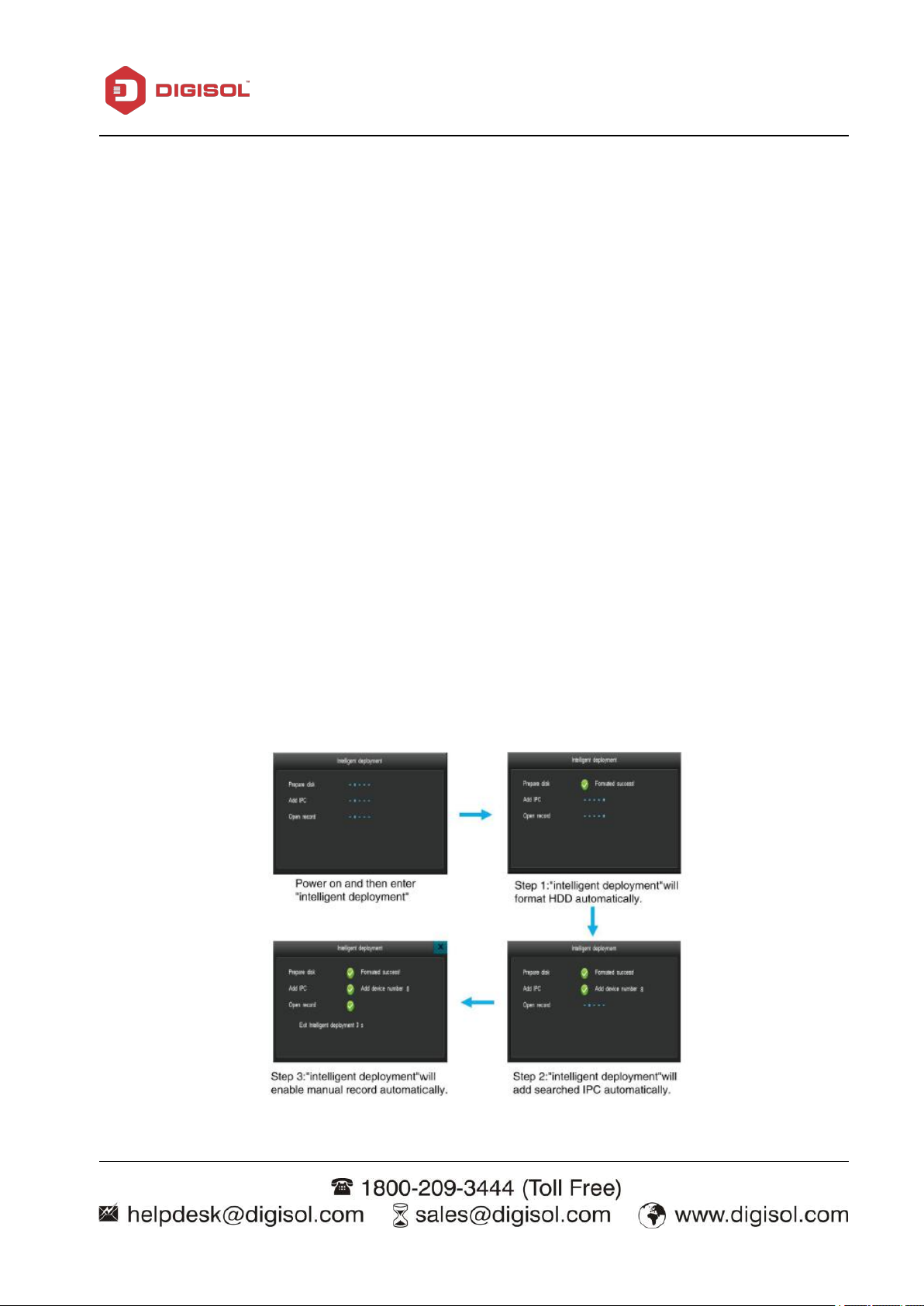
After installing the hard drive, connect HDMI/ VGA cable and mouse on the NVR &
Power ON the NVR. Enter the system and intelligent deployment will run automatically
like below:
Page 11
11
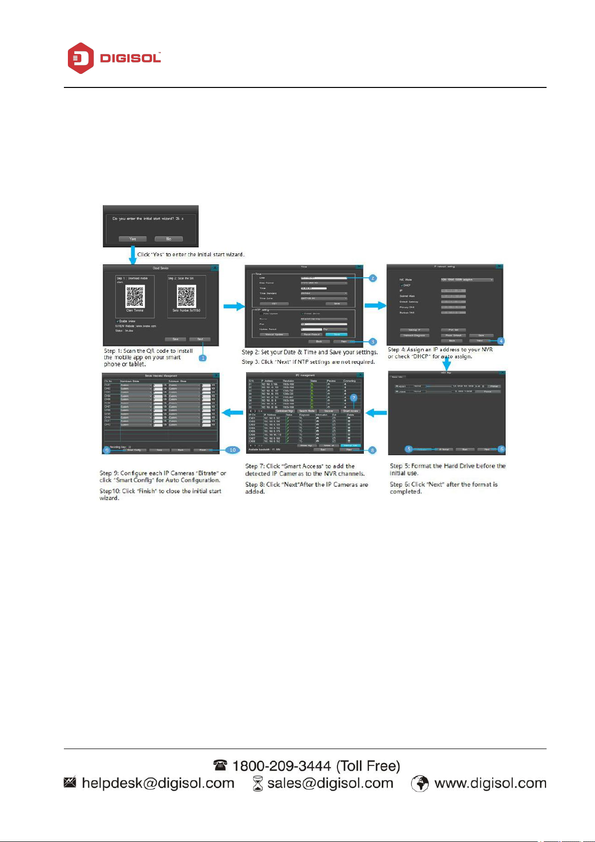
3-3-1 Start-Up Wizard
Once the intelligent deployment step is completed, it will prompt a start wizard as
shown below:
NVR User Manual
Page 12
12
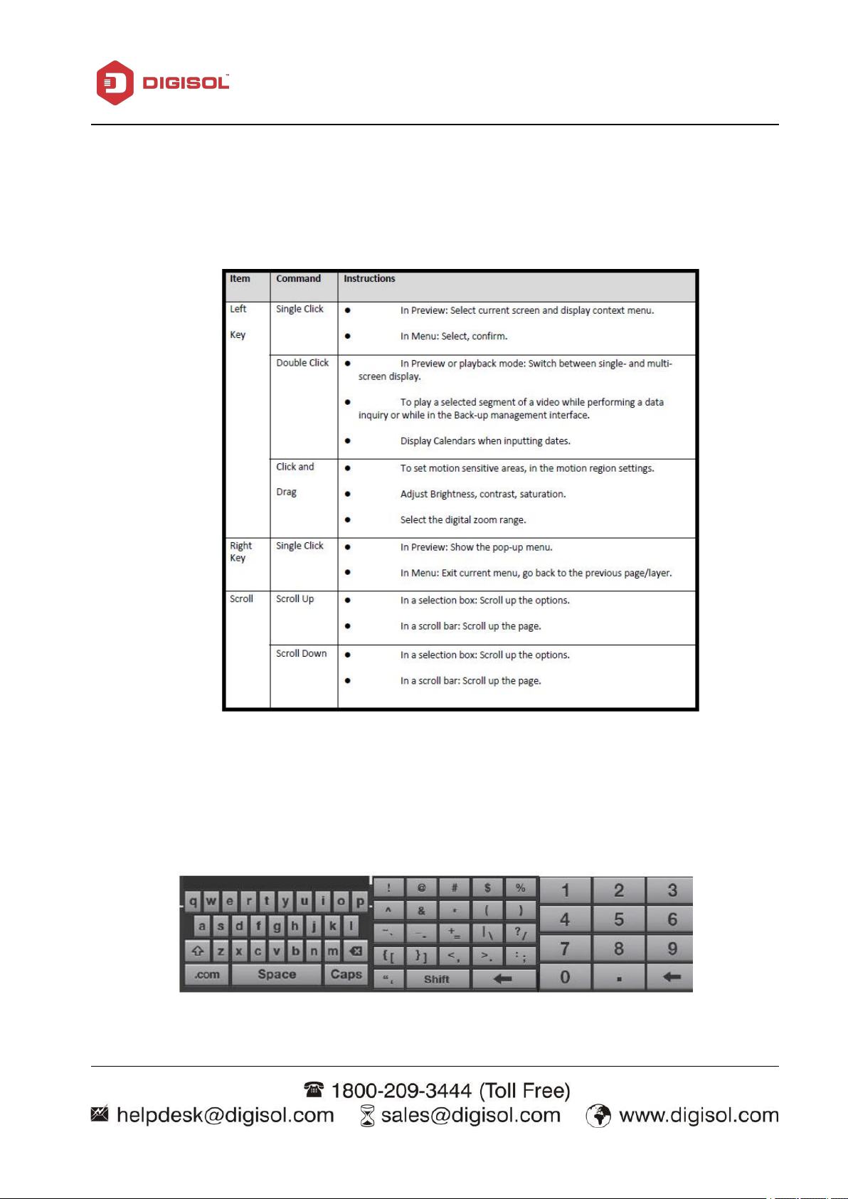
3-3-1-a) Mouse Operation
Control the device with the mouse after connecting it to the USB port.
NVR User Manual
3-3-1-b) Input Method
The virtual keyboard is as shown below:
Page 13
NVR User Manual
13
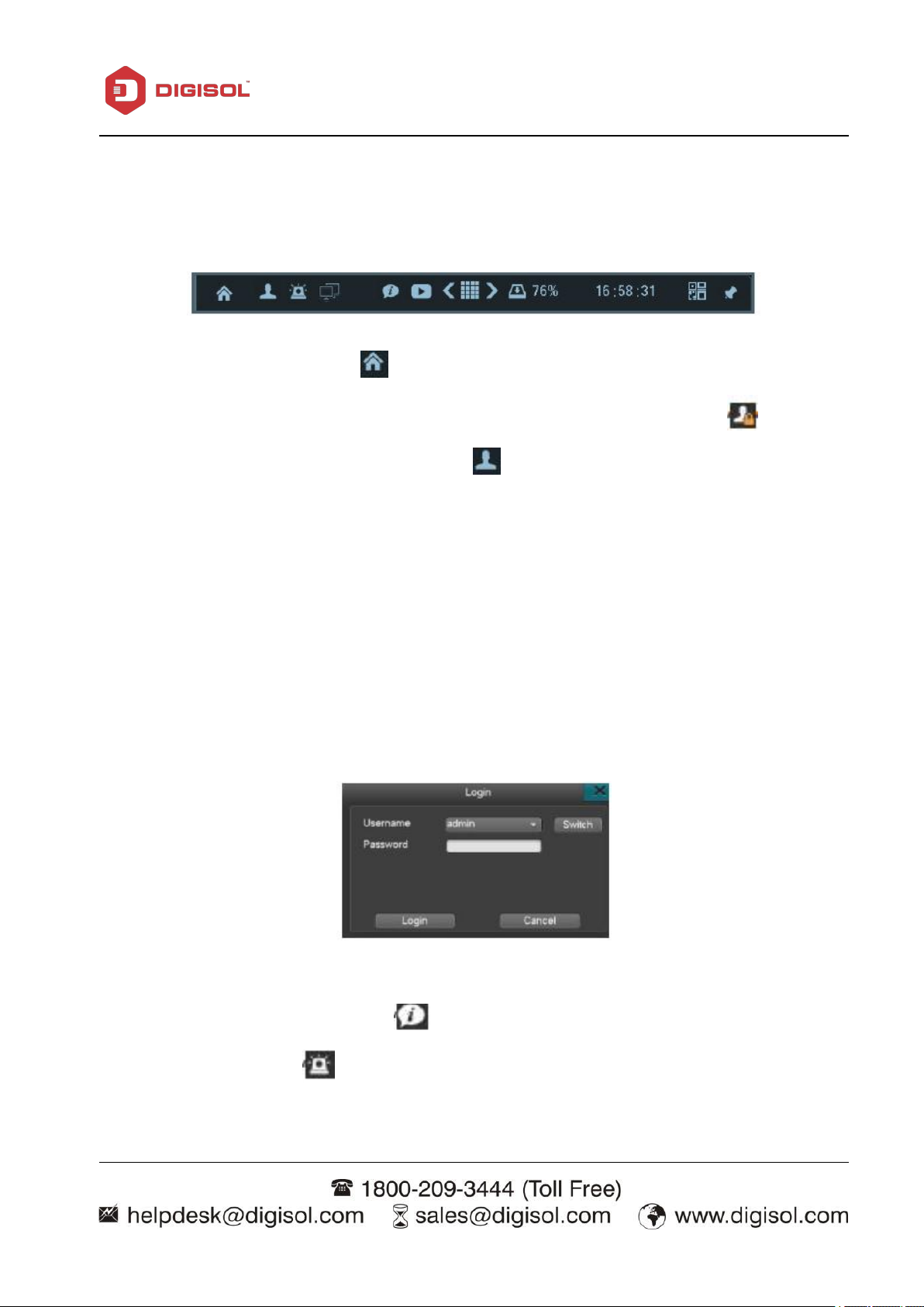
3-3-1-c) Navigation Bar
The Navigation bar will appear as shown below:
1) Menu icon: Single click on the “ ” icon to enter the main menu.
2) Administrator account log in/log out: After powering on the device, single-click “ ” to
Login the administrator account, single-click the “ ” icon to log out of the account. The screen
will be locked after you log out.
Please note:
NVR is free login by default and it doesn’t input username and password please set security
password via System Maintenance> Account to disable Free-login.
a. Default username: “admin”; Default password: “888888”
b. The system will automatically lock itself after three failed login attempt. When the device is
locked, you need to wait 60 seconds to try again.
c. On the login interface, left-click on the mouse to prompt the virtual keyboard, then right-click
to hide the virtual keyboard.
Tip: For security, we recommend you to change the default password.
3) USB icon: Move mouse to this icon“ ”will display USB icon.
4) Alarm: Single-click on “ ” directs you to the alarm status interface. You can check alarm
report information and clear alarm notifications.
Page 14
NVR User Manual
14
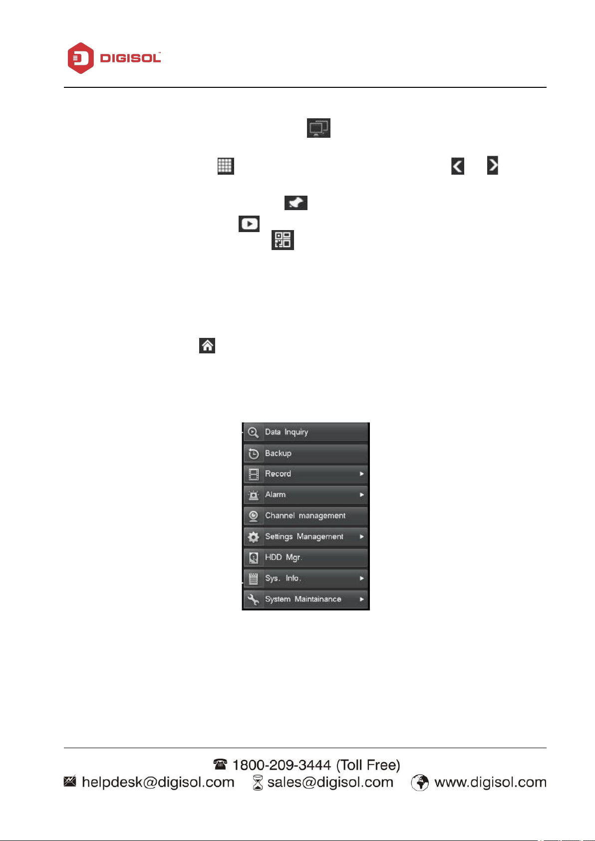
5) Network diagnosis and repair: Single click on “ ” to enter the internet diagnosis interface. You
can start a diagnosis and/or network repair.
6) Multi-view: Single-click on “ ” to adjust the live view screen; single click “ ”or “ ” to
adjust the channel layout.
7) To show/hide navigation bar: Single click “ ”
8) Quick playback: Single-click on“ ” to quickly playback the video from the last five minutes.
9) Cloud service: Single click on the icon “ ” to enter the cloud service interface. You can
switch on/off RealView feature, scan the QR code, and download the mobile App.
3-3-2. Main Menu
After log in, left-click the “ ” icon on the navigation bar or right-click on the live view
page and choose “main menu”
The items on the main menu are as below:
Page 15

NVR User Manual
15
Menu
Description
Data Inquiry
Time Inquiry
Search and Playback the recorded video by entering a
specific date and time
Data Management
To manage the recorded files; you can lock/unlock file
from deletion
Backup
Backup
To format storage devices; search and backup recorded
video to external HDD or USB
Record
Record Parameters
1. Select Channel (Select a camera)
2.Stream type: Mainstream/ Substream
3.Video encoding: H.264/H.265
4.Resolution:
2560*1440/2304*1296/1920*1080/1280*1024/1280*960/
1280*720
(depending on the model of IPC connected)
5. Image quality: Highest/second-highest/ high/medium/
low/lowest
6.Video frame rate: 1-25/30
7.Bitrate type: VBR
8.Bitrate stream: 45K,60K,75K,
90K,100K,128K,256K,512K,768K,1M,1.5M, 2M,
3M,4M, 5M, 6M, 7M, 8M, custom (depending on the
model of IPC connected)
9. Audio: Open Audio Record ( the IP Camera need to
support this function)
10.Motion/Alarm Pre-record:5-30 seconds,
11.Motion /Alarm Delay-record:1-180 seconds alert:
1-180 seconds
Manual
Manually turn on recording of the selected channel
Schedule
Set a recording schedule of a channel. copy the settings
from one channel to another channel by clicking “Copy”.
Motion
1. Select a channel.
2. Continuous Alarm: Alarm will sound until you stop it
Page 16

NVR User Manual
16
Alarm
manually, if motion is detected.
3. Set Motion sensitivity Level; Highest/ Higher/ High/
Medium/Lower
4. Set a motion-detect region.
5. Linkage setting:
a. Trigger Recording/Screen shots: when Motion triggers
an alarm on one channel, you can set other channels to
start recording at the same time.
b. Enable email notifications : when an alarm occurs, the
NVR will send an email to your email automatically, if
email parameters are set in the email setting.
Sensor
You can connect a sensor to the NVR; e.g) smoke detector
Alarm Output
when alarm occurs.
channel will display full screen.
message to your Smart Phone or CMS on PC.
Other Alarms
Enable or disable other kind of alarms: HDD error, Video
Loss, Network Disconnect, HDD Full. POE Conflict.
Manual Alarm
Manually open the external alarm.
Channel
Management
1. Automatically searches the IP camera on the local
network.
2. Add IP Camera one by one.
3. Show the IP address of each camera.
4. Delete IP camera one by one.
5. Check status of each camera.
6. Edit camera’s IP address, change protocol or port
number.
7. Diagnose/check the network connection of IP cameras.
Settings
Management
General
1.Host name: Create a name for the NVR.
2.Resolution:1280*720/1280*1024/1920*1080/3840*2160
3.Supported languages: English
4.Auto lock:/1/3/5/10 minutes
5.Turn on/off the “Display power on wizard”
6. Open adaptive optimal resolution.
7. Enable/disable system beep.
8.Restore factory default.
Page 17

NVR User Manual
17
9.Enable/disable intelligent deployment.
Time
1. Time setting: Manually edit the time setting, change the
date display format and time standard; or set the DST.
2. NTP setting: Automatically update time via internet.
Output
Channel
Setting
1. Set Channel Name.
2. Set Video Mask Area.
3. Video Adjustment: brightness,
contrast, saturation.
4. Set Channel name Position.
5. Set channel name and time display
Sequence
Setting
Set sequence; choose channel,
intervals, and cycle.
Output
Mode
Standard/Bright/So
Network
Network
Manually set NVR IP address or enable
DHCP. Backup IP settings, port
set, and Network diagnosis.
DDNS
Choose a server; set username and
password, DDNS test.
PPPOE
Set up the dial up username and
password to connect via PPPOE.
Email
Settings
Set email server, email account name,
password and email address,
receiving email address, ports, Period,
SSL, email testing.
Advance
d
Settings
Set up UPNP or port forwarding.
Set FTP Upload.
Cloud
Services
1. Download the mobile App, Scan the
QR Code to add your device to
the mobile App.
2. Enable or Disable ivvew: Enable or
Disable Cloud Service
HDD
Mgr(HDD
Management
)
Basic Info
1. Show hard disk and USB disk information.
2. Set HDD.
3. Format the HDD or USB drive.
HDD Group
Assign cameras to different hard drive groups. Display
disk group total/remaining capacity
Storage Setting
Set hard disk overwrite, trigger time, the number of days
of recorded video available, and other parameters.
Page 18

NVR User Manual
18
SMART
Displays hard disk capacity, the serial number, hardware
version, temperature, current health condition, SMART
and other attributes.
System
Device
Information
Displays the device model, channel number, software
version, GUI version, IP address, MAC address, language,
resolution and current user.
Channel Status
Display all IP addresses of the IP Cameras, connecting
protocols, bitrate and video resolution.
Information
POE Status
Display all POE IPC status
Alarm Status
Displays Alarm status of each channel, such as
motion-detect and video loss. Also displays hard disk
errors, Network loss, and over-temperature.
Online Status
Displays all current accounts or users logged in to the
NVR, IP address, login time.
Log Inquiry
Inquire and display system log; backup system log.
System M
aintenance
Quick Setting
Quickly set up time, Network, HDD management, video
parameters, IPC management and cloud services.
Account
1. Add/delete account/groups.
2. Edit User privileges or set user privileges for remote
access.
3. Free-Login (no password required when login from the
console).
Restore to Default
Restore all settings back to factory default.
Upgrade
Upgrade via FTP or USB.
Schedule Restart
Set system restart schedule.
System Shutdown
Log out, restart, or shutdown.
Page 19

19
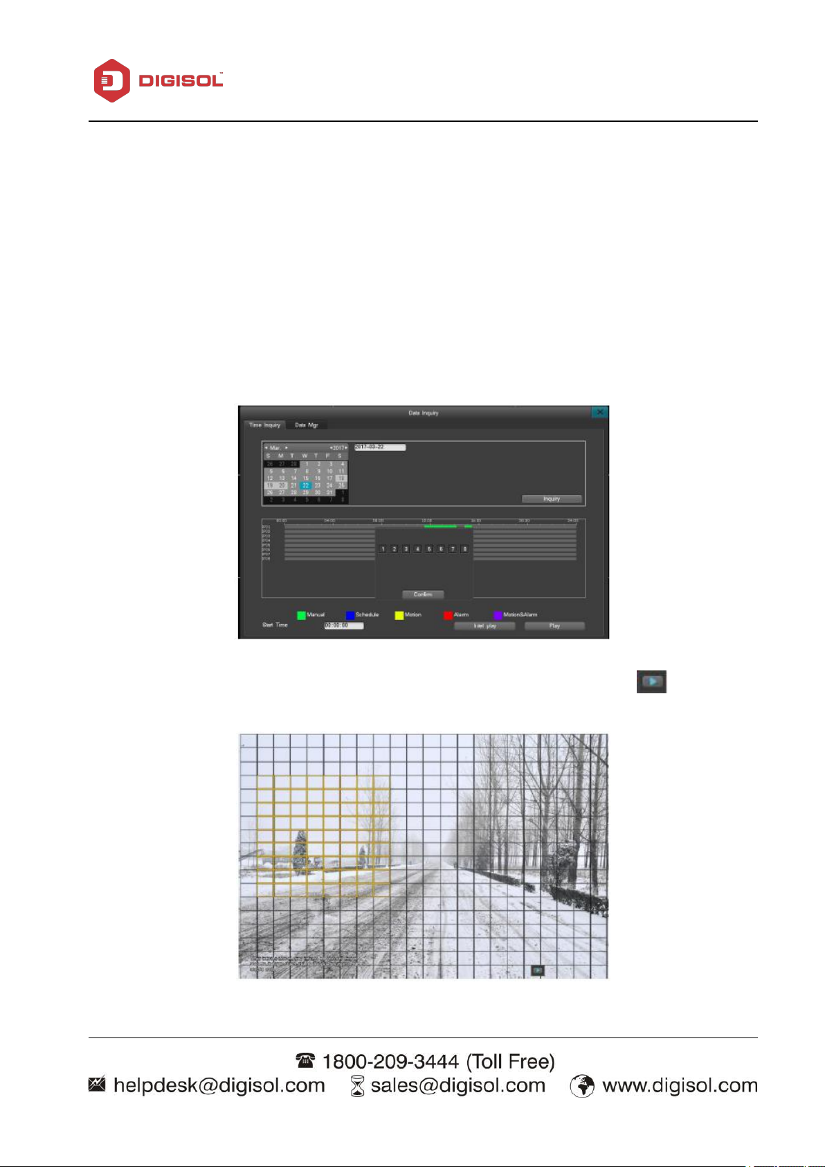
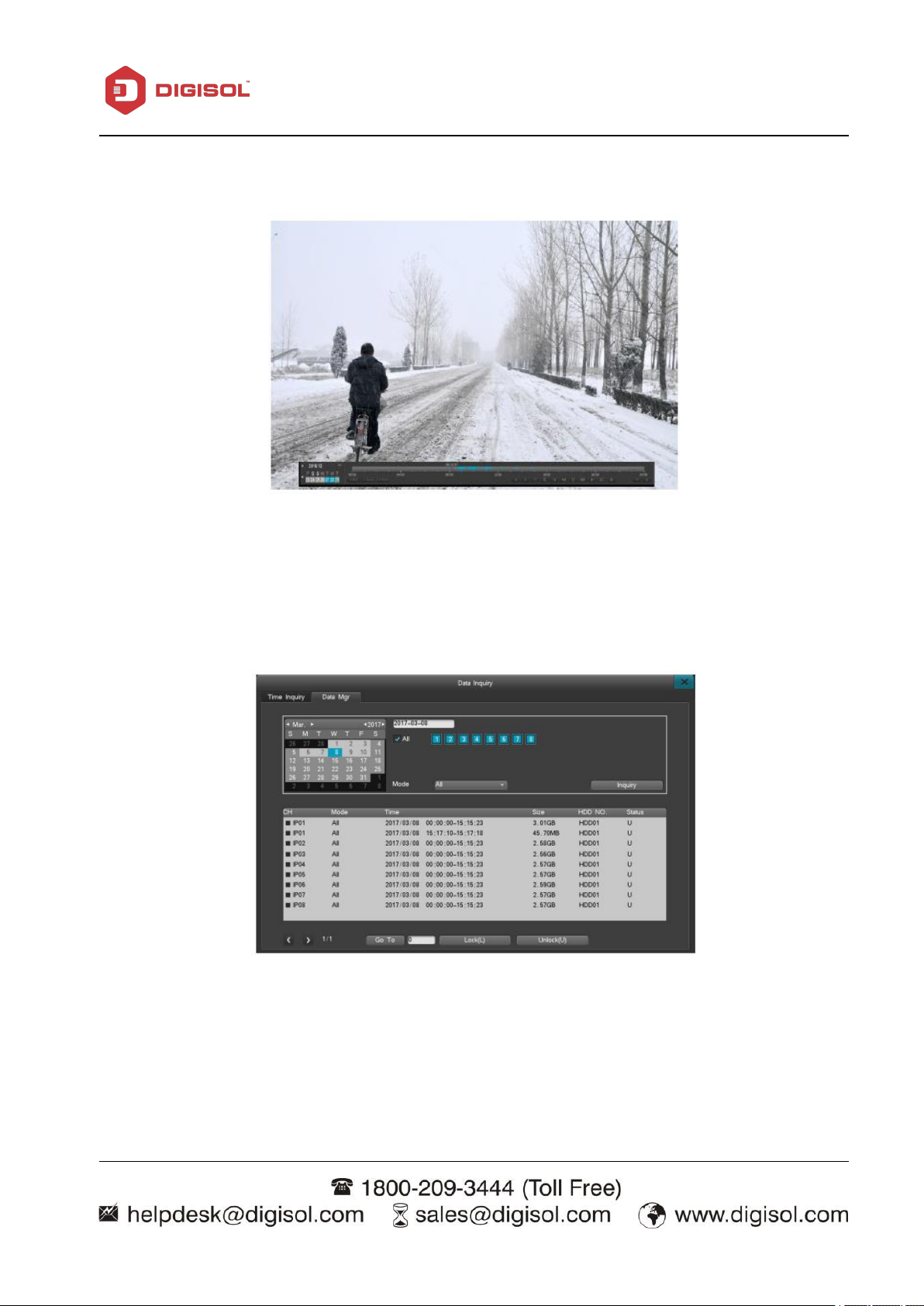
3-3-2-1 Data Inquire and Replay
To enlarge the video when playing, simply move the cursor onto the time-line, and then
Single-click on “Data Inquiry”, as shown below:
NVR User Manual
Inquire by Time
From the “Data Inquiry” interface, choose a date then click “Inquiry”. It will then start a graphical
search, as shown below:
left-click on the enlarge icon once to enlarge the video display of that specific time point. To
restore normal view, move the cursor to the time line and left click the minimize icon.
Page 20
NVR User Manual
20
A dark gray square on the calendar means that there are video files on that date. A pure gray
A green square stands for manual recording, blue indicates scheduled recording, yellow for
2) You can select a zone, hold the mouse left key and drag it to select a zone, click
square indicates that than there are no video files of that date (The light blue square indicates
the selected date on the calendar).
motion detection recording and red for alarm recording.
Intel Play
Intel Play means Intelligent Playback, you can select a zone in the window and click playback, it
will search all the motion that has been detected in this zone, and playback it quickly.
1) Click “Intel Play” and choose a channel and confirm.
Page 21
NVR User Manual
21
3) The NVR will show all the motion that been detected in this zone.
Select the desired channel.
Select the video type of the channel on the drop-down menu.
Double-click the file segment to start playback.
Click on the next/last page icon to view additional pages.
Select a segment to lock down or unlock.
Data Management
From the “Data Management” interface, you can check the video file based on its channel number
or video type, shown here:
Page 22
NVR User Manual
22
Playback: Support Multi Channel playback.
Right-click the mouse to display or minimize the playback control bar.
Area zooming is supported during playback in single-screen display. Please follow the
During playback, you can select a segment of video to back up to a flash drive.
The playback features are as follows:
instructions below for area zooming:
I. Enter the playback screen and then select the enlarge button.
II. Select the area you wish to enlarge on the small screen display.
III. Select/enter the zooming scale to enlarge that area, right-click to deselect the zooming area.
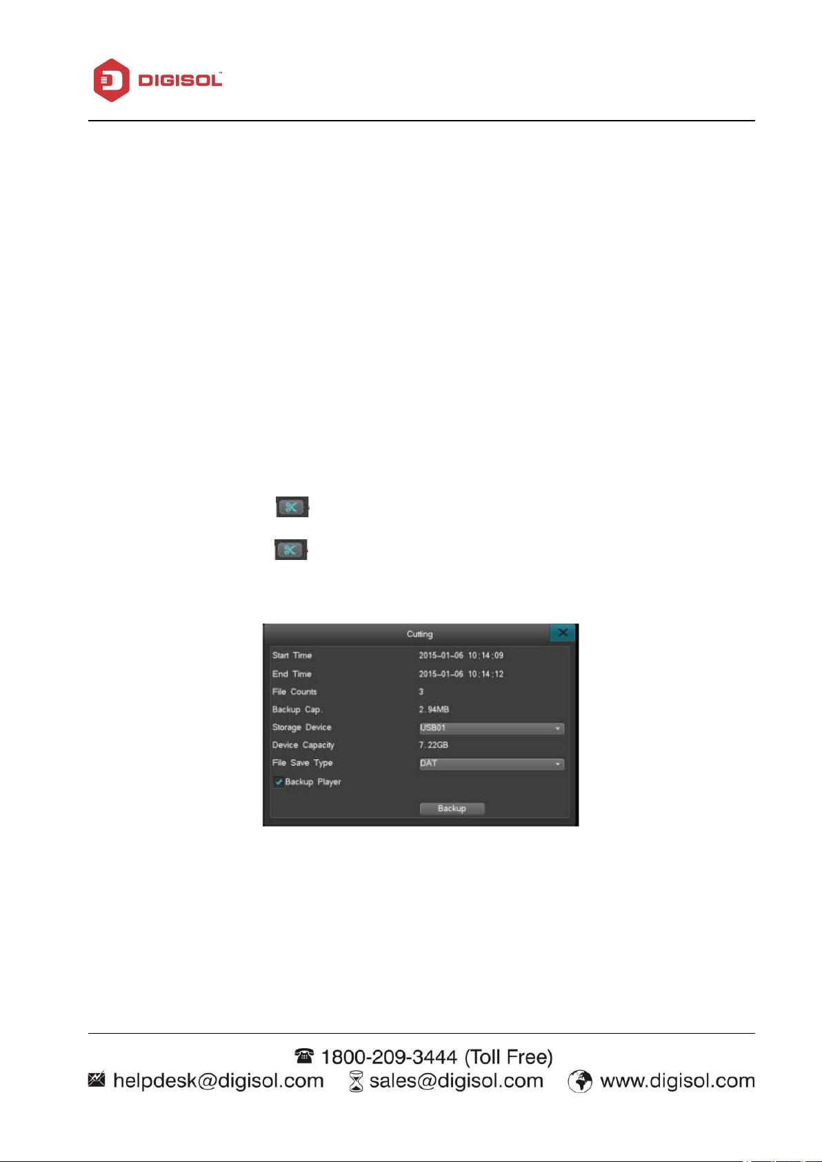
I. Display video data.
II. Select desired video segment.
A. Click on the edit button “ ” on the player to set a start point.
B. Click on the edit button “ ” again to set an end point.
C. The edit backup settings window will then automatically pop up, as shown here:
D. Set all related parameters (storage device, file type, backup player), click the backup button to
complete the process.
DAT data can be searched and played back through the Backup Management settings interface on
the NVR, however on a personal computer, a video player that supports DAT format is needed.
Page 23

NVR User Manual
23
3-3-2-1 Backup Management
This system supports two backup methods, one is USB and another one is mobile HDD. It is better
to use backup device when power on rather than plug in before power on.
1. Backing up files to a remote computer via the internet. Please see the IE IP Camera guide for
internet backup settings instructions.
2. Backing up to a local storage disk. Hot swapping is supported for flash drive and external hard
drives, The backup disk must be in the FAT32 format.
3. To enter the backup management interface, click on “Main menu”→ “Backup Management”.
Backup channel: Choose the channels to back up.
Query time: Enter a start and end time of the file to back up, the maximum time period is one
month.
Backup device type: Choose the device type to query; local HDD storage data or stored files on
other listed devices.
File status: Locked/unlocked.
File type: Choose the type of the video to be backed up.
Backup device: Choose the device to back up files to.
File types: DAT, AVI.
Page 24

NVR User Manual
24
PLEASE NOTE:
1. You must choose a file type before backing up any data or viewing any data from a backup
device.
2. Playback in the NVR will be in .DAT file type only.
Instant Backup
1. In the backup management interface; choose the channels and file status, check the box for
recording,
click “Instant Backup”.
2. To complete the process, select ‘Yes’ at the ‘Confirm to Start Backup’ pop up.
PLEASE NOTE: Execute an instant backup to backup all checked-up data.
Manual Backup
Specific backup instructions:
1. Choose the channel, file status, select the desired video, click “Check”.
2. Select the files to back up, and select “Manual Backup” to enter the backup interface.
3. To start importing all files and complete the backup process, select ‘Yes’ at the ‘Confirm to Start
Backup’ pop up.
4. If there's any video, it can be instantly backed up, no waiting period required.
5. To confirm on the backup file, select the desired file by clicking “Play” to start playing the video.
(PLEASE NOTE: The total size of all current files combined is displayed at the bottom-left corner
“Total Backup File Size ”)
Page 25

NVR User Manual
25
Backup File Display
1. On the backup management interface, select the devices to back up and then click on “Check”.
2. Choose the confirmed video file data and then click on “Play”.
(PLEASE NOTE : Backed-up files can only be played back on a single track. Data cannot be
dragged to move around during playback. Also, the system will automatically backup the video
player when you choose to backup DAT video files.)
Scheduled Backup
Click “Scheduled Backup” on the Backup Management interface, as shown here:
The options include: Turn on scheduled backup after start up, scheduled backup channel selection,
video type selection, regular backup time point selection, backup device, overwrite mode, file type.
The host will then start automatic backup on the preset time cycle.
Page 26

NVR User Manual
26
3-3-2-3 Video Settings
Video settings include: Recording parameters, manual recording and schedule recording sub menu,
as shown below:
Recording Parameters
When using the NVR to record, it is important to set up the video parameters beforehand. Video
parameters affect playback and disk space consumption. After logging in, follow the path of
“Record”→“Record Parameters” to enter the video parameter setting interface.
Note: When you have set the parameter in IP Camera web interface, please click “refresh” first to
synchronize the parameter to the NVR.
Page 27
27
Channel number: Select from the drop-down menu.
Bi-stream: Select the bit stream type (mainstream/sub stream).
Resolution: The resolution range is determined by the connected IP camera. Not all
model cameras will have the same resolution options.
Image Quality: six levels (highest, second highest, high, medium, low, lowest).
Frame per second: 1-25/30 FPS.
Bitrate: Based on the connected IPC, a customized bitrate should be within the supported
bitrate range of the IPC.
Pre-record: The NVR will record video before the event occurs. The value ranges from 5 to
Delay-REC: The NVR will continue to record after the event has ended for a defined value.
Click “Copy” to copy that channels parameters to other channels.
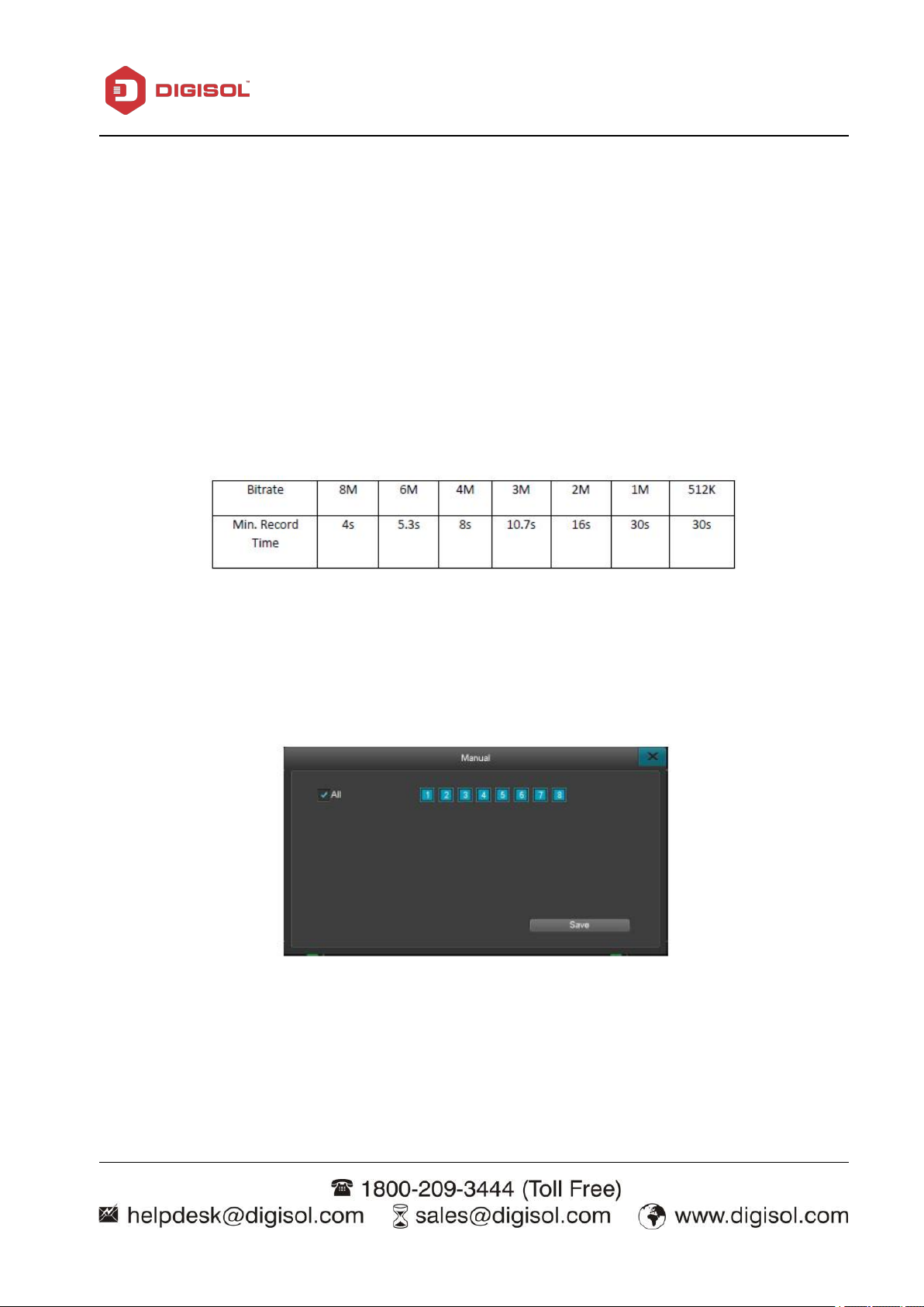
The manual recording interface, as shown below:
The channel buttons are displayed in blue when the feature is turned on and gray when the
Once the manual recording feature is activated, it will keep recording until turned off. If
30 seconds depending on the bitrate stream.
The value ranges from 1 to 180 seconds.
NVR User Manual
Manual Recording
feature's turned off.
there is an abrupt power loss, recording will stop and restart automatically once the power is
back on.
Page 28

NVR User Manual
28
Left-click to select the day to be recorded. You can select multiple days, select all for every day,
Click and Drag the left mouse key to set up a recording time segment
Click ”Save” to complete the process. Click ”Copy” to copy all settings to all channels.
Scheduled recording
After logging in, click “Record” > “Schedule” to enter the scheduled recording settings interface, as
shown below:
1. Channel number: Select the corresponding channel.
2. Follow the instructions below to set up the time schedule:
or a
particular day of the week, depending on your needs.
(or double-click to enter the interface to adjust). You can have up to six different time segments
(PLEASE NOTE: by default the time is displayed in 15 minute increments).
Page 29

NVR User Manual
29
3-3-2-4 Alarm Settings
Alarm Settings menu includes three sub menus (Motion, Alarm Output, Other alarms), as shown
here:
Motion Detect
After logging in, click on “Alarm” > “Motion” to enter the motion-detection settings interface, as
shown below:
Setting up the motion detection feature:
1. After logging in, click “Record”→“Record Parameters”, set up pre-record and delay-record
parameter.
2. Select the channel to record
3. Motion detection sensitivity levels: Levels available from lowest to highest. When there's any
motion detected on the channel, the system will automatically start recording and send off an alarm.
On the lowest sensitivity level, the system will only send off alarms when there's significant activity
detected.
Page 30

NVR User Manual
30
Trigger video: Choose which channel will record when motion is triggered.
Linkage Setting: Enables e-Mail Alerts/Notifications.
PLEASE NOTE: Once continuous alarm is turned on, the system will keep sending off the
4. Motion Area: Set the detecting point by left-clicking on the preview screen and dragging the
cursor across desired squares, release the left mouse key and the highlighted squares are the
detection area. Right-click on the mouse to return to the motion-detection interface to save the
setting. Left-click twice to deselect the area.Yellow area indicates the detection area.
5. Set the schedule (please refer to the instructions from schedule recording).
6. Linkage Setting:
alarm when detecting motion. If this feature is turned off, then there will only be a one-time
report throughout the entire recording cycle despite how many times activities are detected.
Sensor Alarm
Alarm record setting instructions:
Step 1. After login, navigate to “Main Menu”-> “Record”-> “Record Para,” to set pre-record and
post-record time.
Step 2. Navigate to Main Menu -> Alarm -> Sensor Alarm to set the alarm record setting. Please use
below picture for reference.
Step.3 Choose Normal-On or Normal close base on the device you are using.
Step.4 Choose the sensor number.
Step.5 Set up the alarm schedule. The schedule can be every day, on a particular day, or certain time
frame
Step.6 Set up the desire channel to be recorded when sensor is triggered in the linkage setting.
Step.7 Blue icon in the output setting indicate the alarm output is enabled; gray indicate the feature
is disabled.
Page 31
NVR User Manual
31
Step.8 Click on the email check box to enable email.
PLEASE NOTE: Once continuous alarm is turned on, and the sensor alarm triggered, it will
continuous alarm.And in the alarm status interface, the continuous alarm cannot be cleared
manually.
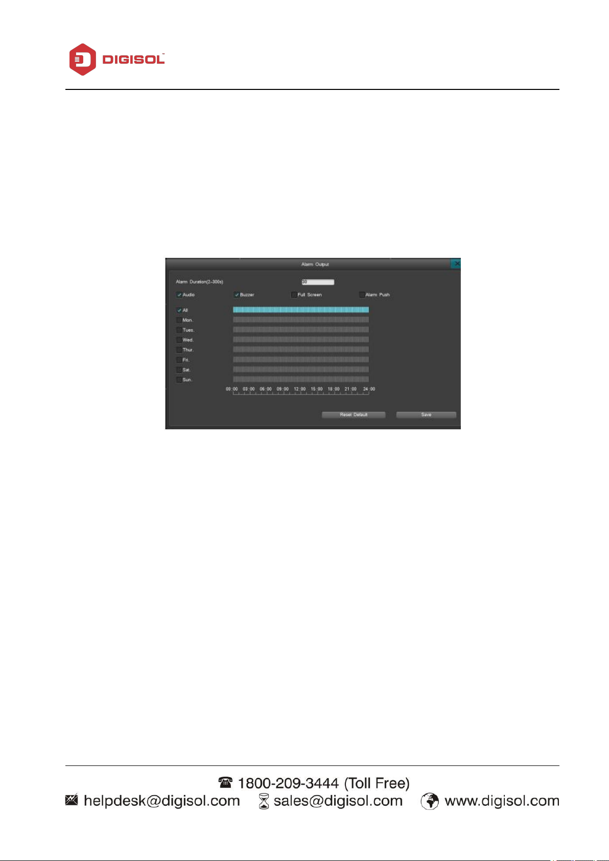
Alarm Output
The alarm output settings: Alarm duration, Audio/Buzzer and full-screen mode.
Alarming duration: 2 to 300 seconds (default: 30 seconds); The duration of the alarm sound or
buzzer when motion is detected.
Audio buzzer: When this feature is turned-on, the system will sound the built-in buzzer or output
audio alert through the HDMI connection.
Full-screen mode: If the system is displaying multiple cameras when an alarm or motion is triggered,
the channel with the event will display full screen.
Alarm Push: When selected, the NVR can push a message to your smart phone. The ‘RealView Pro’
must be installed in the smart phone to use this feature.
Page 32
NVR User Manual
32
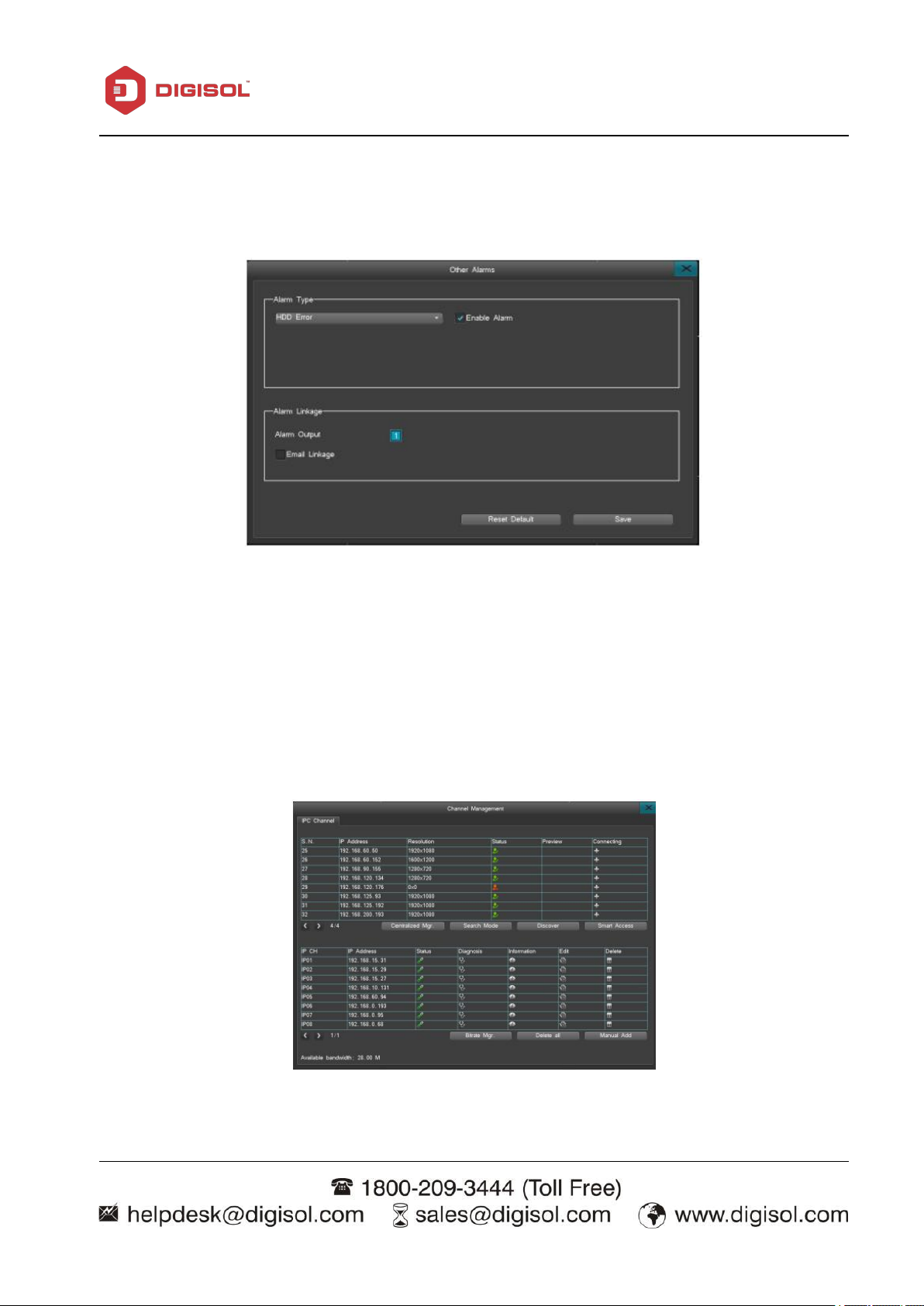
Other Alarms
After logging in, click “Record” > “Recording Parameters” and enter the Other Alarms interface,
as shown below:
Alarm types: HDD errors, Video lost, network disconnect, HDD Full, POE Conflict.
Alarm linkage: Whenever an alarm is triggered, this feature will automatically connect to your email
and upload the alarm file to your inbox. This feature is supported in all the alarm types.
3-3-2-5 Channel Management
After logging in, click “Main Menu”> “IPC Management”to enter the IPC Management interface,
as shown here:
Page 33
NVR User Manual
33
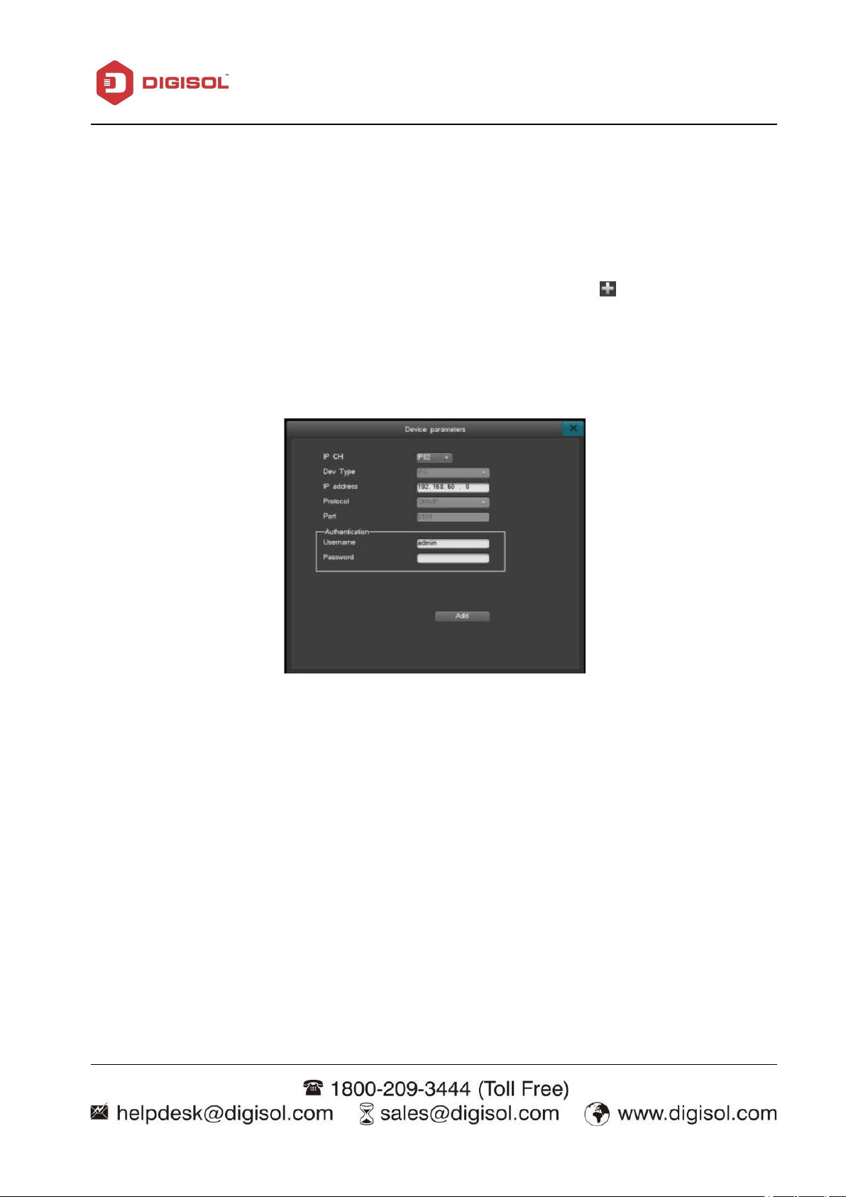
1. To manually add an IP camera: Click “Manual Add” to enter the settings interface as shown
IP Channel: Select the system channel of the IPC.
IP Address: Enter the IP address of the IPC.
Username: Enter the username for the IPC.
Password: Enter the password for the IPC.
After setting up the above parameters, click “Add” to
add the IPC to the system.
2. Smart Access: Tap on “Smart Access” and the system will automatically add all IP Cameras to the
After entering the IPC Management interface, the system will automatically search all IP Camera's
that are within the same network and displays them in a list. Available cameras are shown on the
upper half of the interface and the cameras already paired are shown in the bottom half.
Add IP cameras
There are three ways to add an IP Camera: manually adding on the IPC Management interface (as
shown below), via the Smart Access feature or left-clicking the add icon (“ ”) once to add camera
directly.
below:
Instructions:
Enter/set up the parameters in the following sections:
system in the same order shown in the upper section. Before using the “Smart Access” feature to
add the IPC’s, users can sort the order of the IP Cameras using the following instructions:
Page 34
NVR User Manual
34
To sort by IP address: Move the cursor to the available IP addresses on the IPC list and
To sort by resolution: When the system detects IP Cameras of different resolutions, move the
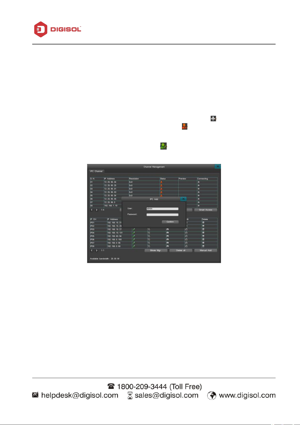
3. To add an IPC from the channel window: click the corresponding “ ” icon for each available
left-click the mouse once to sort the IP cameras base on IP address.
cursor to the “Resolution”, left-click once to sort base on resolution.
(PLEASE NOTE: Smart Access can only add the IP Cameras that are online at the moment,
those that are offline will not be added)
camera When the status of the IPC is displayed with the “ ” icon, the adding IPC interface will
open; (as shown below) reminding you to enter the username and password for the camera you
wish to add. An available camera with the icon “ ”the username and password is not required.
(PLEASE NOTE:After adding the cameras successfully, it will only appear on the connected IP
Cameras list and won't appear on the list of available IP Cameras).
Page 35

NVR User Manual
35
Deleting IP cameras
The delete option applies to connected cameras only. You can delete one-by-one or delete all
cameras at once.
1. To delete IP Cameras one-by-one: on the list of connected IP Cameras, click on “ ” and select
“Yes” when prompted
2. To delete all cameras at once: To delete all connected cameras, click “Delete All” and select “Yes”
when prompted.
PLEASE NOTE: After the camera is deleted, it will be moved back to the available camera list on
the upper half of the interface.
Other Instructions
1. Discover: Left-click the “Discover” button once to refresh the available IP camera list.
2. Flip pages: When there are multiple IP Cameras in different pages, left click the “ ” or “ ”
icon to flip pages.
3. Status: The connection status of an IP camera is color-coded. Red: Abnormal, the IPC is
disconnected and there is no video signal. Green: Normal, the IPC is successfully connected and
currently online,. Orange: A certain channel is abnormal, but the video images can still be displayed
in general.
4. IP channel diagnosis: Left-click the “ ” icon and enter the IPC diagnosis interface which will
allow you to diagnose video streams
5. IP channel information: Left-click the “ ” icon to enter the IP channel information interface.
Channel numbers, channel names, IP addresses, current resolution of the mainstream, the status,
protocol, port, manufacturer, model and hardware version of the IPC.
6. IP channel editing: Left-click on the “ ” icon to enter the IP channel settings interface to change
the IP address and the username/password.
7. Search mode:It can support different search mode like Smart, General, H-mode, Z-mode, Y-mode.
Switch the mode will make device restart and all added IPC will be deleted, so please make sure if
you want to switch it.
Page 36

NVR User Manual
36
IPC Centralized management
IPC management support to configure batch of IPC IP, both searched IPC and added IPC can
support this function.
Click “IPC management” to enter the interface like picture:
IPC management interface contains IP address, resolution, status etc., support add IPC and
edit added IPC.
Batch configuration which can adjust the IP address and steps like below:
• Choose some IPC and click batch configuration button.
• Set started IP and save it in the batch configuration interface.
• Adjust the IP address successfully.
PLEASE NOTE:IPC management interface decides the member of IPC automatically. When set
the started IP and other chosen IP will configure one by one.
Page 37

NVR User Manual
37
3-3-2-6 Settings Management
Settings Management includes: General settings, Time settings, Output settings and Network
settings, as shown below:
General Settings
After logging in, click “Setting Management”> “General Settings” to access the general settings
interface, as shown below:
Host name
Set up a name for the device.
Resolution
Available Resolution are: 1280*1024,1440*900,1280*720,1920*1080,3840*2160
Page 38

NVR User Manual
38
Auto lock
The system is able to lock down the system interface after a preset period of inactivity. The default
for auto lock is three minutes, with a custom range of one to ten minutes available.
Display ‘Start-Up Wizard’
After selecting and saving the setting to display the ‘Start-Up Wizard’, every time you turn on the
device, the system will automatically inquire whether or not you want to enter the start-up wizard.
The available options are: activate the RealView, set system time, internet/network settings, disk
management and encoding parameter settings. You can simply select cancel to skip this option, and
exit the wizard.
Language
Supports both English and Chinese by default.
Save and enable beep
Turn on/off the beep sound.
Intelligent deployment
This Model supports intelligent deployment function, which means after power on, the device will
add IP camera, format HDD and open recording automatically. The users only need to connect the
all the cable,install the Hard drives, then the NVR will start to work. It only takes 3 minutes to finish
this intelligent deployment.
Intelligent Deployment steps is as below
1).Choose “Main Menu” - “Settings Management”- “Genneral”, check” Intellegent Deployment”
2).Then after power on the NVR out of box, the NVR will add IP camera, Format HDD, Open
Recording automatically.
3). Please Uncheck “Intellegent Deployment””after power on the NVR, because if not, when you
reboot the NVR, the process will do it again.
Page 39

NVR User Manual
39
Time settings
After logging in, enter the time setting interface through “Settings Management”→“Time Settings”,
as shown below:
Time Settings
The menu is for setting up or editing current system time and supports direct editing and editing via
calendar (to edit via calendar, please double-click on the calendar to enter editing mode.
1. The interface supports 9 different time formats.
2. Supports both the 12-hour and the 24-hour clock format.
Daylight Saving Time (DST)
Click on the daylight saving time button and enter the settings interface (as shown below) and then
set up the beginning and ending point of daylight saving time (choose to either enter the precise
dates or the starting and ending weeks).
Page 40

NVR User Manual
40
1. Server: The current default time server can be adjusted If the default time server cannot be
NTP Settings
The Network Time Protocol, which obtains current time via the internet time server and set the
system time for the NVR. (system default: time.nist.gov port:123, default time zone:GMT+08:00)
connected, you can then choose another time server, or uncheck the “Default Server” option on the
interface and enter the time server you wish to use.
2. Port: To connect the time server via the internet. The system is SNTP-based and only
supports TCP.
3. Time zone: The system supports settings of all 26 time zones:
GMT+0 (London) ,GMT+1 (Berlin), GMT+2 (Cairo), GMT+3(Moscow), GMT+5 (New Delhi),
GMT+7 (Bangkok), GMT+8(Hong Kong/Beijing), GMT+9 (Tokyo) , GMT+10 (Sydney), GMT-10
(Hawaii), GMT-9(Alaska), GMT-8 (Pacific Time), GMT-7 (Mountain Standard Time), GMT-6
(Greenwich Mean Time), GMT-5 (Eastern Standard Time),GMT-4(Atlantic Time),
GMT-3(Brazil),GMT-2 (Mid-Atlantic)
4. Auto update cycles Intervals are hour, day, or week. All options are within the range of 1-60 times
per cycle. “Auto Update” will update the time on the device automatically.
5. NVR needs internet access to perform NTP.
Output
Select “Main Menu"→ “Settings Management”→ “Output” as shown below:
Page 41
NVR User Manual
41
1. Click “mask area” in Record Mask or All Mask modes, Left-click and drag the mouse to select a
2. Right Click to exit to front page, and save it.
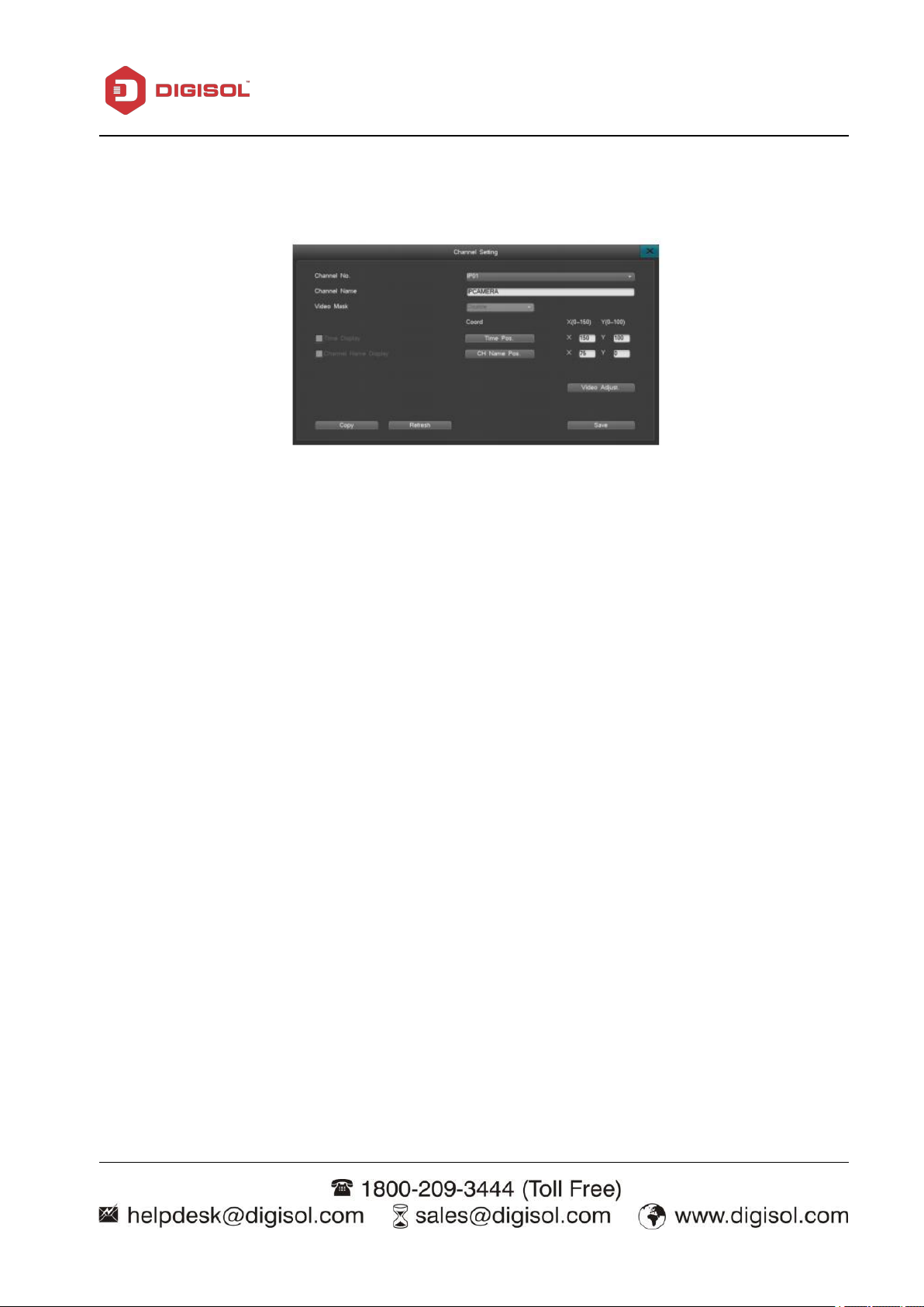
Channel Settings:
On the “Output Settings” interface, select the “Channel Settings” option and enter its interface, as
shown here:
The channel settings interface allows you to edit channel parameters: channel name, video mask,
video parameters, and channel name location.
(1) Channel Name
Name the channel. Channel name can be up to 30 characters.
(2) Video Mask
There are 4 options for video mask: Disable, Preview Mask, Record Mask, All Mask. A maximum
of 4 mask areas can be set.
Disable: Disable video mask function.
Preview Mask: Mask an area which won’t be seen on live view.
All Mask: The area will be masked in live view and during playback.( Video mask need to be
supported by IPC)
How to set a video mask:
mask area; up to 4 areas are available. Double left-click to clear the mask area.
Page 42

42
(3) Video Channel Adjustment
2. Left-click the “ ” or “ ” to change the value or drag the bar left or right
Click “ Video Adjust” to modify the video parameters.
(4) Adjusting methods:
1. Select a Channel Number.
NVR User Manual
(5) CH Name Pos
Click “CH Name Pos” to switch channel name position, the channel name position is set to top left
as default.
(6) Time Pos
In the channel setting interface, click “Video Adjust” to access video parameter setting interface; it
also can access via right key and adjust Brightness, Contrast, Saturation.
Sequence
Select “Settings Management” > “Output”> “Sequence” to enter Sequence interface.
Page 43
NVR User Manual
43
Steps for setup:
1. Check “Sequence” to enable the feature.
2. Set up the sequence period by entering the desired time within the available range: 3-60 seconds
3.Set up the sequence channels and choose means enable.
4. Set up the sequence format, the default is 1 image, but you can choose between 1/4/8/9/13/16
image/s by clicking on the respective icons.
5. Set up the channel sequencing. The default starting channel is Channel 1. User can select a
different starting channel and adjust the order of channels by clicking the “ ” button to select another
channel number from the drop down menu. If there are multiple screens, you can click the “ ”or“ ”
button and then enter the number of screens to sequence and set up the channel sequence.
6. Click “Save” to save the settings.
(PLEASE NOTE: the sequence feature is active only when the system is in locked down state)
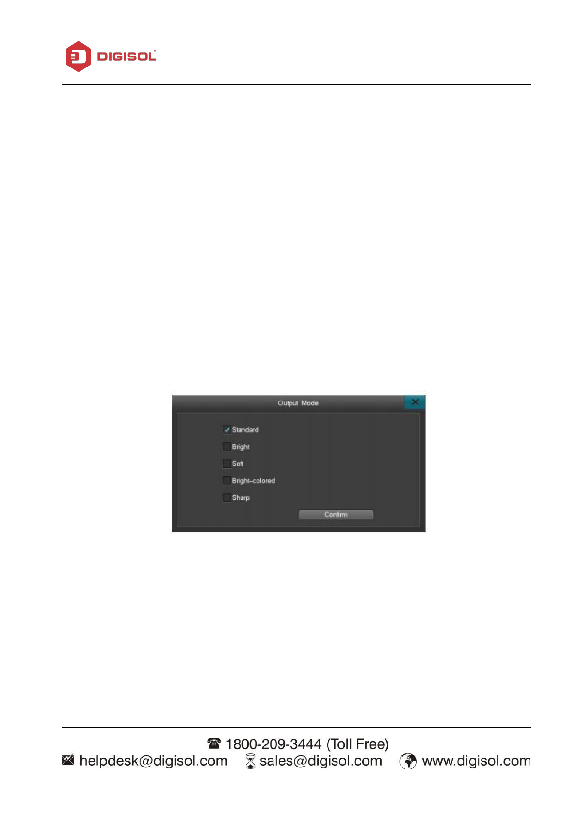
Output Mode
Output: Change the image color and brightness on your monitor.
Page 44

NVR User Manual
44
Network Settings
After login, click “Settings Management” > “Network Setting” to enter the interface shown below:
From the Main Menu > “Settings Management” > “Network setting” > “Network ” to enter the
interface shown below:
There are four different ports: Command port, HTTP port, update port, RTMP port.
HTTP port: Internet Explorer port (system default: 80), the format for Internet Explorer is
“http://IP”. When switched to another port, the format for Internet Explorer access should be
“http://IP: port number”
Command port: Default 8101; range from 8000-9000
Internet Diagnosis: Check the current NVR network. User can repair the network.
Page 45

NVR User Manual
45
DDNS test: Check if the registered domain account is available.
DDNS Service
After entering the Network Settings Interface, select “DDNS” to enter the DDNS settings interface,
as shown below:
Domain: Select super-ddns server, select “Default”(Default Domain is the device’s last 8 bits of
the MAC address. For example, If the MAC address in “system info” is e4:7d:5a:00:29:47, then the
domain is 5a002947 ). Click “login” to auto-register a domain. You can also type in any domain that
has not been used before, then click “login” to auto-register the domain.
Sign up for a domain name on their official web site, and enter the correct required information in
the NVR click “save”. The registered domain name can be used to access the device from pc/laptop
or phone app. Set up the username and password you registered for on any of those sites, save the
setting and then the system will be able to update the domain name.
Page 46

NVR User Manual
46
Username: ADSL account username.
Password: ADSL account password.
Auto Reconnect: When this feature is selected, ADSL will automatically redial after disconnect.
Click “Save” to save the credentials.
PPPoE Settings
After entering the “Internet Settings” interface, select “PPPOE” for Dial up Settings interface, as
shown below:
NOTE: your PPPOE username and password can only be obtained from your Internet Service
Provider.
Email Settings
After entering the “Network Settings” interface, select “Email Settings” to enter the ‘Email Settings’
interface, as shown below:
Page 47

NVR User Manual
47
Input your Email server.
Input user name, which should be email address chosen as the sender email address and
Input Sender Email and Receiver Email addresses.
Receiver email can be multiple email addresses, separate the addresses with “;”. Limited to
Port is 25 by default. Please check with your e-mail provider for the correct port number.
Set the e-mail upload period. If multiple alarms are triggered within the same period, only
Click “Save” when done.
Turn on SSL if required by your email provider.
The available email alarms include: Motion detection, video loss, hard disk errors and disk full. For
selected alarms, notification can be sent to your email inbox when an alarm is triggered.
Setting up Email notifications
password for that email account.
256 characters total.
the first alarm will send out an email notification.
Platform Server
This series support platform server and GB28181 server. Device can connect to CMS automatically
via add register ID. GB28181 is the standard protocol which defined information transmission,
exchange, control, communication protocol structure, transmission, exchange, control of city
surveillance alarm and requirement of control and transmit, protocol interface. It used to design
security project of surveillance alarm network system, system detection and accept and some other
device develop and manufacture for reference. Click “Platform Server” in Network interface which
can enter GB28181 like picture as above.
Page 48

NVR User Manual
48
Platform Server configuration:
1. Add device on platform server: input device name, choose “connect automatically” in device type,
video channel number, alarm input number, alarm output number and so on, and then confirm to
add.
2. Click the adjust icon of adding device to get the register ID.
3. Input device register ID, platform server IP and platform server port(default is 8000) on upper left
of NVR interface.
4. When connect successfully, platform can operate the device.
Advanced Settings
The UPNP (Universal Plug and Play) feature is able to automatically open ports; enabling WAN
access to the NVR on user’s LAN network.
In the “Advanced Settings” interface, select “UPNP” and click “setting” to enter the interface.
Page 49

NVR User Manual
49
The steps to use UPNP to access a NVR camera are as follows:
1. Set up the NVR network IP address to the same network segments as the router. DHCP is
recommended when using UPNP.
2. On the UPNP interface, check the “Turn on UPNP” option to activate the UPNP feature. If the
users wants to add additional ports, please click on the “add new” option.
3. Click “Add new” button to enter the “UPNP PAT add” interface. User can set up the service name
and choose the appropriate protocol (TCP/UDP), NVR port number and router port number (for
your own convenience, you can set the router port to be the same as the NVR port). After setting up
the parameters and saving the settings, you can now return to the main UPNP window.
4. From there you will see a newly added port mapping, and see the addition on the UPNP settings
interface
(please note: for some routers, there may not be that list where the UPNP option is displayed). To
verify whether or not UPNP is in effect.
PLEASE NOTE:
1. UPNP needs to be supported by the router. If UPNP is not supported by the router, please setup
port forwarding on the router or set up DMZ.
2. The HTTP port, Command port, and RTMP port need to be forwarded in the router for Online
live view.
Page 50
50
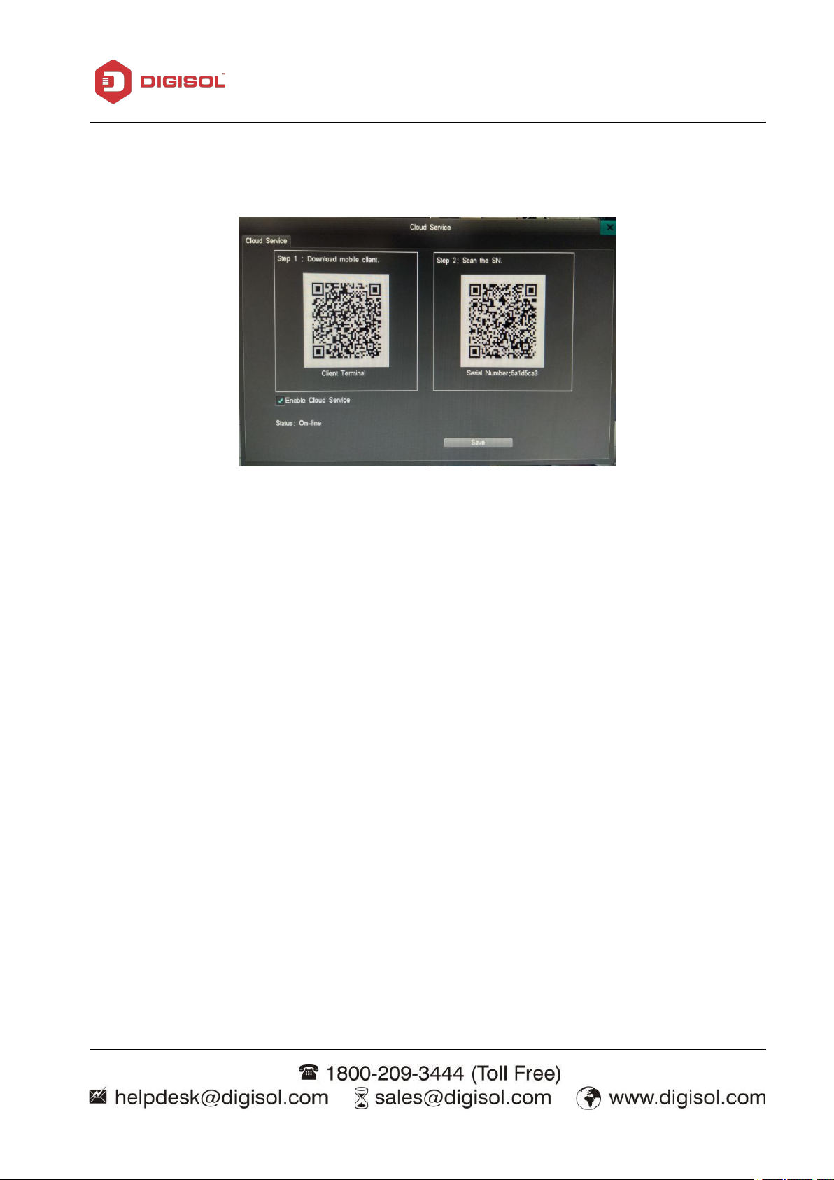
Cloud Services
Turn on/off “RealView”: Check “Turn on RealView”;click “Save” to activate the feature. When
Download the mobile client: Scan the QR code to download the mobile App.
Add your device:Scan the QR Code on the right to add the device to the App.
Click “Network setting” > “Cloud service”
NVR User Manual
activated successfully, you can see the status change from “Offline” to “On-Line”
PLEASE NOTE:
- Before adding your device, register an account through the mobile App.
- You can download a quick guide from our website to help you with app connection.
- The Cloud interface can be accessed from the ‘Start up Wizard”, the status bar and from the
Internet settings.
Page 51

NVR User Manual
51
(1) Basic information: Displays the information for each Storage Device, HDD or USB, system
3-3-2-7 HDD Management
“Main Menu” > “HDD Management” to enter the HDD Management interface.
User can check the hard drive’s basic information, HDD Group, Storage setting and SMART
information.
Basic Information
only supports FAT32 format.
(2) Disk attributes: There are two attributes ─ R-W(Read and Write) and R-O(Read-only). User
can change the attribute from R-W to R-O in order to prevent data loss. How to Set: Click the icon
“ “ and select “Yes” on the pop up window to change its attribute.
(3) HDD format: Select the HDD you want to Format or choose “All format” to clear and format
all HDD storage.
PLEASE NOTE: Format the HDD when installing the HDD to the NVR the first time. System will
not record video if HDD is not formatted.
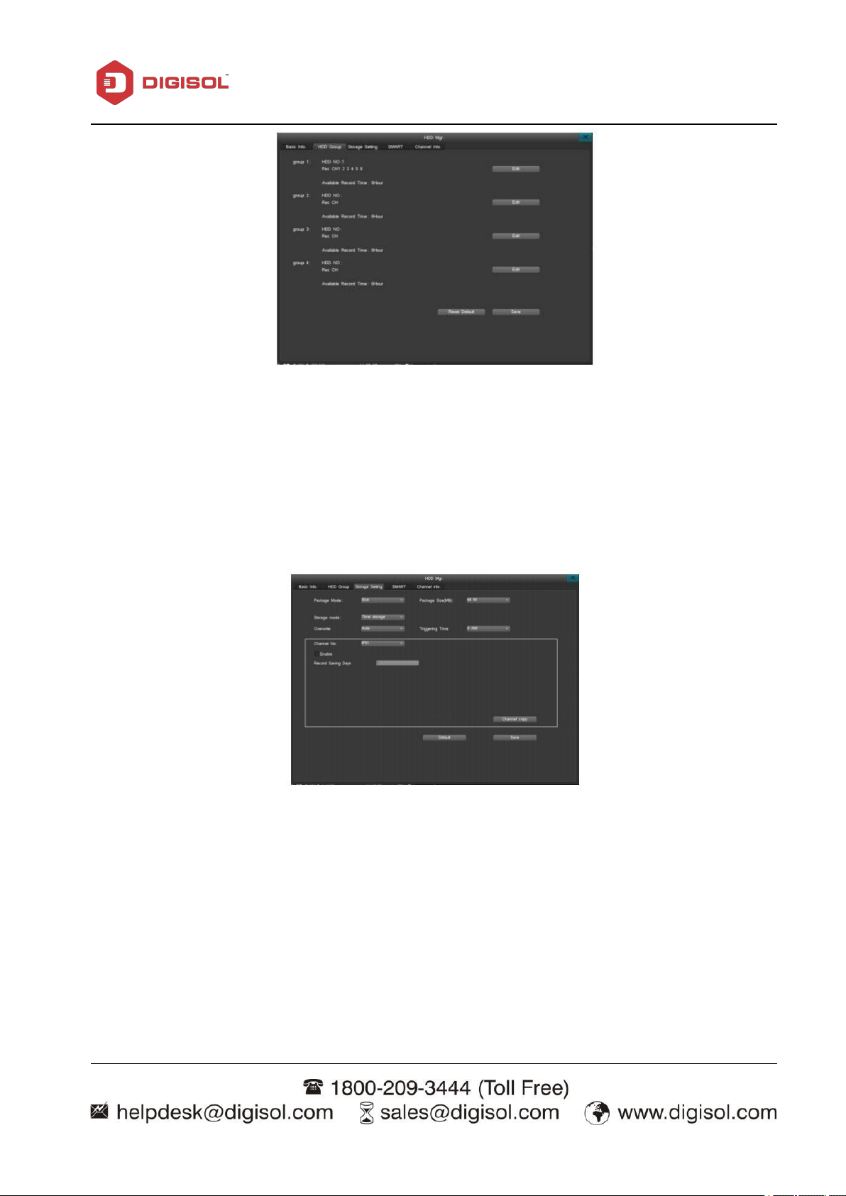
HDD Group
Setting an HDD Group allows the selected channel to be stored in a certain HDD.
Click “HDD Group” to enter the following interface.
Page 52
NVR User Manual
52
The interface shows the info of each group; click “Edit” to change settings.
HDD NO: Assign HDD number to the group.
Rec: Assign the channels to be stored in this HDD group.
Available Record Time: Max recording time in the remaining storage for the HDD group.
Storage Settings
Select “Storage Device” on the Disk Management settings interface, as shown here:
Overwrite images: “Auto” is recommended. “Auto” will automatically overwrite the earliest
records when the HDD is full, if the setting is on “Manual”, user needs to confirm to overwrite
when prompted by the disk full alert. The device will stop recording until you confirm to overwrite
the disk.
Packing Method: Including 2 packing methods – by size, time and non-packing. When you select
packing by size, you can set package size (64M, 128M, 256M, 512M, 1024M optional). When you
select packing by time, packing time range is from 1min to 99min. The system will store and backup
record data as your configuration if you enable one packing method. For example, if you set 128M
packing size, the system will store each 128M record data as subsection.
Page 53

NVR User Manual
53
Triggering time: Set a schedule to check the HDD storage.
Channel No: Choose the channel whose data will be automatically deleted when the
HDD is full.
Select “Enable” to activate recorded data auto-delete function.
Record Space: Available setting record space to certain channel
Available record time: calculated record time according to record space
Available configurable capacity: Total record space provided by system HDD
Surplus capacity: Surplus record space capacity (after deducting the assigned record space to
Channel Copy: Copy the channel configuration to other channels, to realize mass setting.
Recording saving days: set how many days the data will be stored. (For example: if set for 7
Storage Mode: Including 2 storage modes – Time storage mode and Space size storage mode.
You can set record storage size and start time of each channel. In time storage mode, you can set
number of record storage days to each channel, and when the HHD is full, the data of channel won’t
be covered in setting number of storage days. In space size storage mode, you can assign specified
record space to different channels. When record space (of one channel) is full, the system will stop
recording for this channel. If you enable space size storage mode, HDD group function won’t be
available.
channels)
days, them system will delete the 1st day’s data on the 8th day)
PLEASE NOTE: When the file or disk has been set as “locked down” or “read-only,” data cannot be
overwritten or deleted.
SMART
“Main Menu” > “HDD Management” as shown below:
Click SMART to show the HDD model, serial number, hardware version, temperature, health
condition and other SMART attributes and status.
Page 54

54
Channel info.
NVR User Manual
Channel information displays start recording time and recording days of all channels.
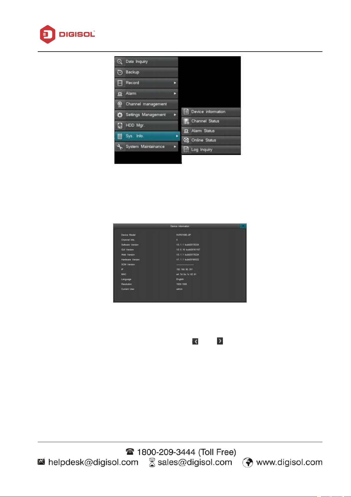
3-3-2-8 System Information
System information interface is as shown below:
Page 55
NVR User Manual
55
Device Information
Displays NVR information such as: device model, software version, hardware version, IP address,
MAC address, language, etc., as shown below:
Channel Status
Quickly check the current status and recording status of all channels. Displays the camera’s IP
address,Protocol, resolution and Bitrate. Click on the “ ” or “ ” icon to flip through the pages, as
shown below:
Page 56

NVR User Manual
56
Quickly inquire system channel status and record status. IP channel interface table displays real time
total received code rate, information table displays current IPC IP address, protocol, record
definition, total received code rate. Click icon “ 、 ” to check channel status of the other page.
See the interface picture on the left below.
In record status interface, it displays record status information of the channels currently connecting
IPC, including channel number, record type, image quality, definition, audio status, code rate. Click
icon “ 、 ” to check record status of the other page. See the interface picture on the right above.
Page 57

NVR User Manual
57
Alarm Status
The alarm interface is as shown below:
Displaying the alarm information for each channel, including motion detection alarms (in yellow),
video lost alarms (in blue).
Click on the Status indicator in the navigation bar to go to the Alarm status interface. Click “Alarm
Clear” to clear all alarms.
Online Status
Displays: All current logged in user accounts, users IP address, login time.
Page 58
58
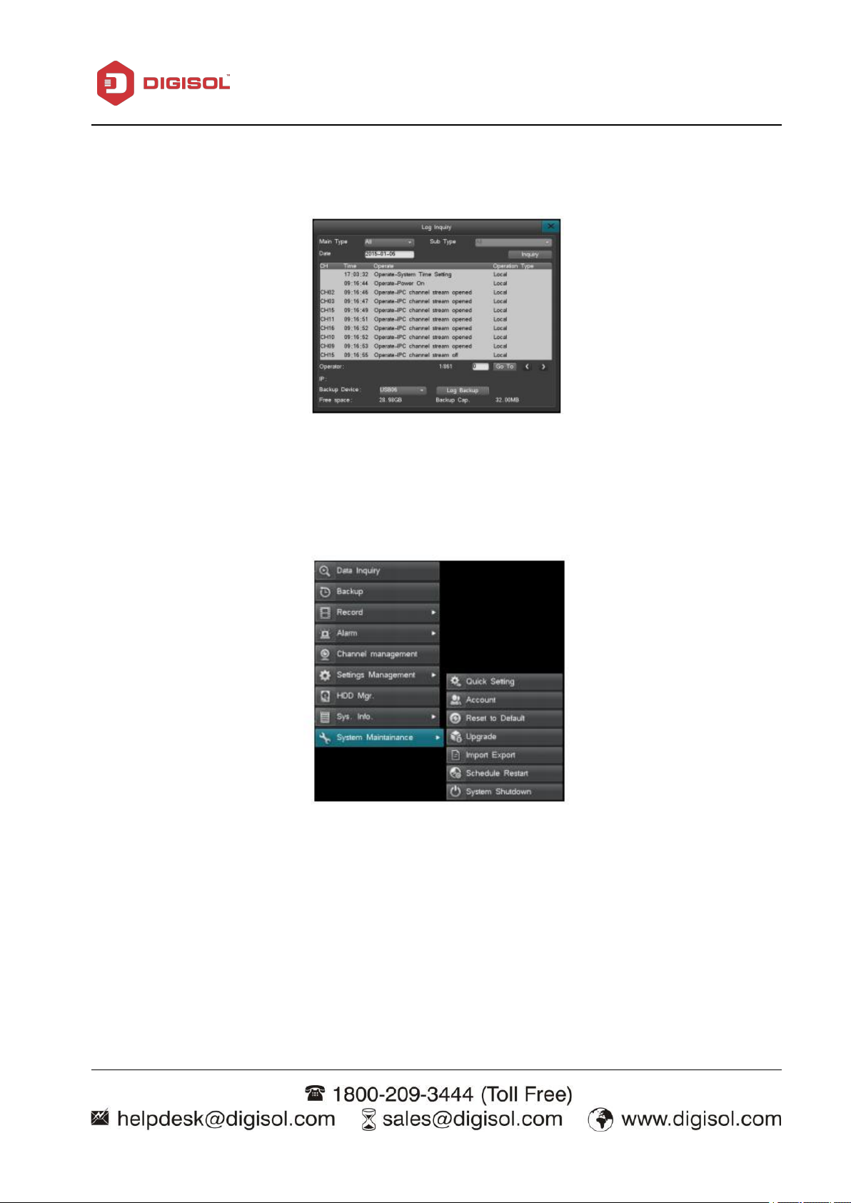
Log Inquiry
System login inquiry, as shown below:
3-3-2-9 System Maintenance
NVR User Manual
From ‘Main Menu’ > “System Maintenance”;menu is as shown below:
Quick Settings
Quick settings will bring up the Start- up wizard, allowing quick set-up of the “Cloud service”,
“Time Setting”, “Network Setting”, “HDD Mgr”, “IPC management”, “Code parameter”.
Note: Please click “save” to apply changes.
Page 59
NVR User Manual
59
Add/delete user account: Click “Add” to add an account to the User Account List. Click
To edit the password: Click “Edit” to change the password.
Supports MAC and IP address binding; when set, only the PC with specific MAC address can
Before upgrading firmware, please backup important video files and data. Note the current
Please ensure that the internet connectivity and the power supply are both stable before
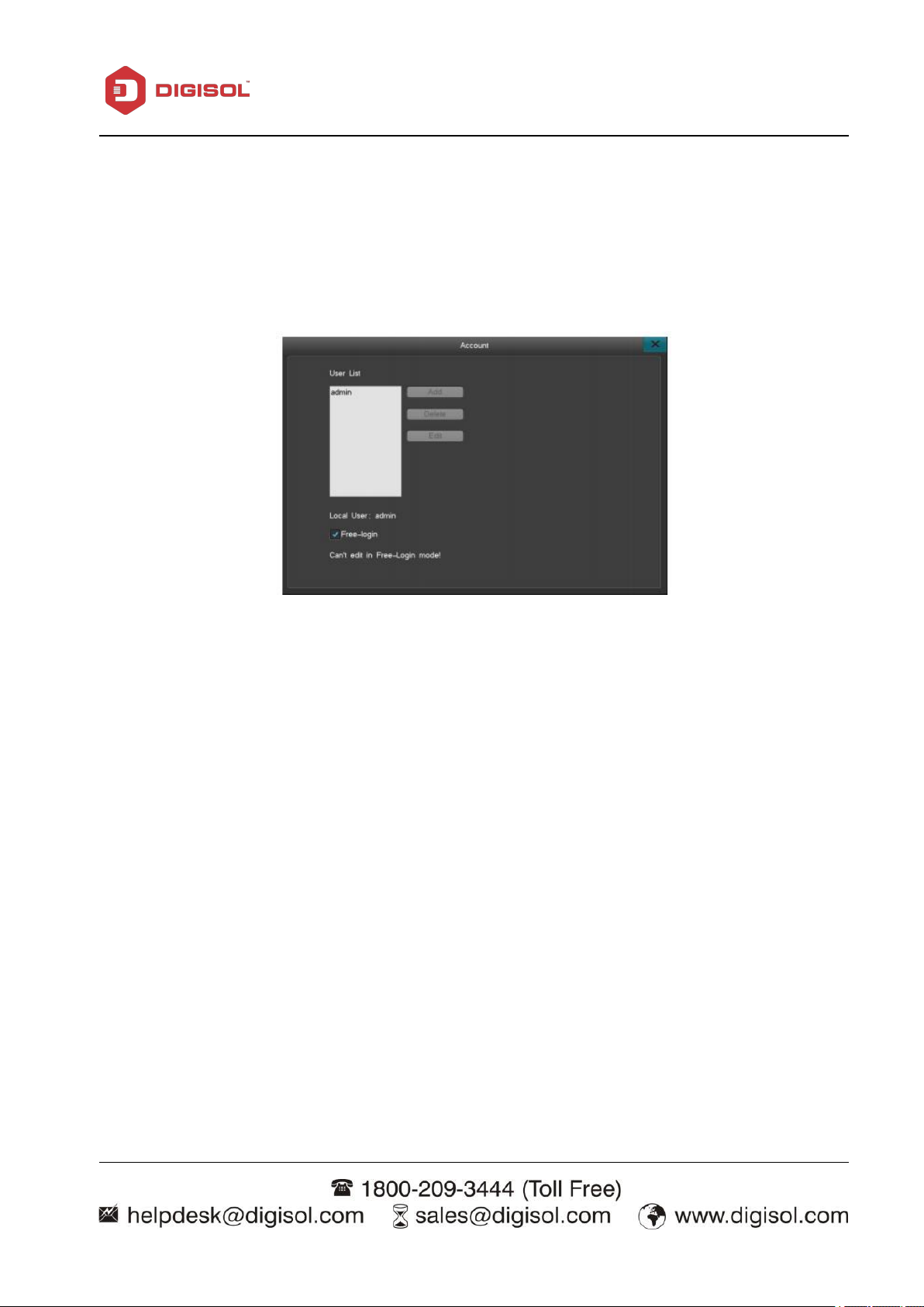
Account
The default username is “admin”, the default password is 888888. The admin account has full
authority on the device and is able to establish up to 15 additional user accounts. The admin account
must determine the access permitted for each additional user account. For system security, it is
recommended to change the default password.
User Account Management:
“Delete” to delete an account.
remote access the device.
Factory Default Settings
To reset to factory settings: choose an individual category or categories to be reset, or reset all for
full reset.
Upgrade
firmware version in order to restore it if the upgrade attempt fails. If you encounter any problem
or do not need the new features of the newest version, then stop the upgrading process.
Page 60

NVR User Manual
60
Before upgrading, please confirm that the file is compatible with your device. Please check the
Please do not modify the firmware in any way. Support will not be provided if the firmware is
Upgrade through Web Browser.
Upgrade via USB device.
Upgrade via FTP.
Type the IP address of the NVR in your browser. Login to the system.
Click “Configuration” (top of screen), click “Maintenance” (from the list on the left) click
Click “Upgrade” After successfully upgrading, the admin password will reset back to default.
upgrading. Any connection failure or power outage occurred during the process will result in an
upgrade failure.
information such as device model and boot interface. If you are unsure about the compatibility,
please do not execute the process.
modified.
There are three ways to upgrade the firmware (please read the instructions carefully):
Upgrade from Web Browser:
“Browse” to upload the file “Upgrade.bin”
Page 61

61
Upgrade via USB Device:
Copy the upgrade.bin file into the root directory of the USB/flash drive. The flash drive must be
Connect the flash drive to the NVR, the NVR will pop-up a message, confirm it.
After upgrading successfully, the device will pop up a message box displaying “Local Upgrade
After successfully upgrading, the admin password will reset back to default.
Double-click the FTP server software on your computer and follow the Start-up Guide to
Designate a root directly on the hard drive where the upgrade file is located, set up the
After finishing the setup process, the system automatically directs you to the server settings
Turn on the FTP service.
The upgrade steps are as follows:
in FAT32 format.
Complete”. The device will restart.
Upgrade via FTP:
The upgrade steps are as follows:
NVR User Manual
establish an account name and password on the server.
access ability for each account (access to downloading must be set up).
to set up the server IP address and server port.
Left-click on “System Maintenance” at the main menu, select “Upgrade via FTP” under “Upgrade
Management”, as shown below:
Enter the FTP server information.
Save the settings and click FTP upgrade.
Page 62
NVR User Manual
62
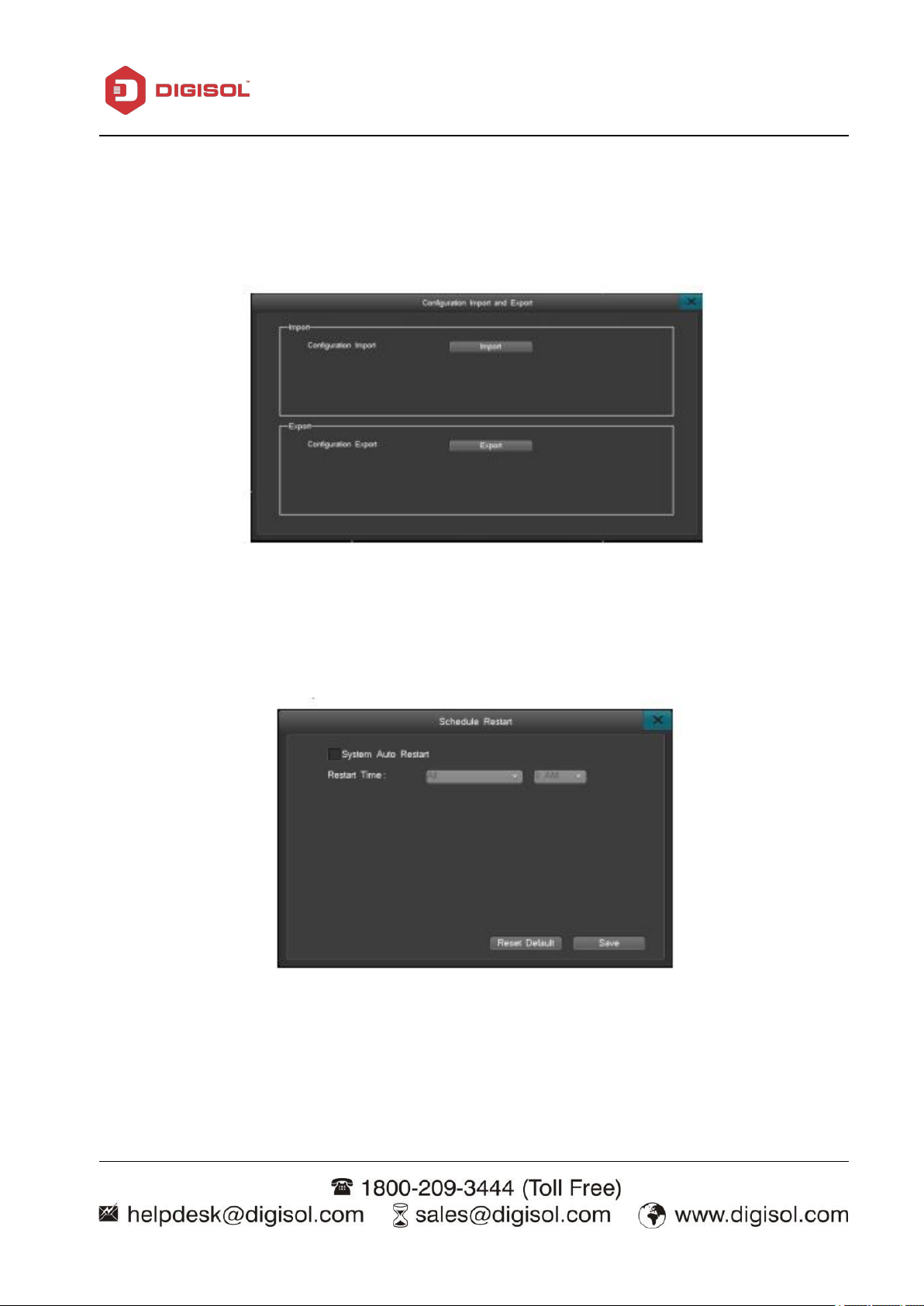
Import and Export
This function allows users to copy all settings from one NVR to another NVR An external USB
drive is required to save the setting.
Schedule Restart
Click “Main menu”→ “System Maintenance”→ “Schedule Restart” to enter the interface of
‘Scheduled Restart’, as shown below:
To enable schedule restart, click the ‘Scheduled Auto Restart’ box and save the setting. When it's
time to restart the device, a notice will display “It is now time for a scheduled reboot, do you want
to reboot the device now.” Click on “Yes” to confirm restart or “No” to cancel it. The system will
automatically reboot itself after 20 minutes If no choice is made.
Page 63

NVR User Manual
63
Logout: This option will logout the user and locks down the device.
Shutdown: select “Shutdown”, and select “Yes” at the pop-up window to shut down the
Restart: click “Restart”, the system will restart.
4. Introduction to Web View
(A) Access the device via LAN
System Shutdown
Click “Main menu” → “System maintenance” → “System Shutdown” to log out and power off or
restart the device. The interface is as shown below:
system.
Please Note: Set the firewall security level to low or medium if error occurs
Disable or uninstall any browser add-ons, if the web interface is not loading properly.
Please make sure DirectX9.0 is installed. Internet Explorer version 6.0 or newer and Adobe Flash
Player is required.
Page 64

NVR User Manual
64
1. From a computer or laptop on the same network as the NVR, bring up a command prompt
2. The NVR and PC should to be in the same IP segment, for example, their IP addresses should
3. Enter the NVR IP address in the address bar on Internet Explore or a browser of your choosing in
(terminal if using a Mac). Ping the NVR IP address to make sure it is accessible.
both be 192.168.0. XXX. If the NVR IP address is not on the same IP segment, for example
192.168.2.XXX, please make sure DHCP is enabled or manually change the NVR IP address to the
same IP segment as the PC. If the NVR and your PC is on the same IP segment but you cannot
access the NVR, please consult your network administrator.
the format of “HTTP://(your IP address)” or “HTTP://(your IP address : the port number)”
(B) To access the device via WAN:
Method 1. If there's a static WAN IP address available, the user can assign the static IP to the NVR
and access the NVR directly using the static IP address, from a browser, phone application or Client
software. However, this is not recommended because the NVR does not have a firewall and direct
Internet access opens the NVR to attacks.
Method 2. If there is PPPOE connection available, click “Menu”→”Internet Settings” →”PPPOE
Settings” to enter the interface. Once all the information is entered, please use the IP address
provided by your PPPOE provider to access the device.
Method 3. Port forward the device on the router, then connect through the WAN IP address using a
browser, phone application or Client software.
Page 65

NVR User Manual
65
1. The NVR cannot boot up normally.
i. The power supply is not correct.
ii. Switch power supply line is not connected properly.
iii. Switch power supply is damaged.
iv. The program updating is wrong.
v. The hard disk is damaged or the hard disk lines are broken.
vi. The front panel is damaged.
vii. The main board of the NVR is damaged.
2. The NVR reboots automatically or stops working after boot up.
i. The input voltage is not stable or too low.
ii. The hard disk is damaged or the hard disk lines are broken.
iii. The power of the switch power supply is low.
iv. Frontal video signal is not stable.
v. Bad heat radiator or too much dust or bad running circumstance for
vi. The hardware of the NVR is damaged.
3. System cannot detect hard disk.
i. The hard disk power supply line is not connected.
ii. The cables of the hard disk are damaged.
7 FAQ and maintenance
7-1 FAQ
If the problems are not listed, please contact the local service or call the Toll Free service. We are
willing to offer the service.
Possible reasons are as follows:
Possible reasons are as follows:
the NVR.
Possible reasons are as follows:
Page 66

66
iii. The hard disk is damaged.
iv. The SATA port of main board is damaged.
4. There are no video outputs in single channel, multiple channels and all
channels.
i. The program is not matched. Please update the program.
ii. The image brightness is all 0. Please restore the default setup.
iii. There is no video input signal or the signal is too weak.
iv. The channel protection or the screen protection is set.
v. The hardware of the NVR is damaged.
5. I cannot find the video files in local playback mode.
i. The data line of the hard disk is damaged.
ii. The hard disk is damaged.
iii. Update the different program with the original program files.
iv. The video files to look up are covered.
v. The recording is not on.
6. The local video is not clear.
i. The image quality is too bad.
ii. The reading program is wrong. Reboot the NVR.
iii. The power to the camera is not proper.
iv. The hardware of the NVR is damaged.
7. There is no audio signal in the surveillance window.
i. It is not an active tone arm.
ii. It is not an active sound box.
Possible reasons are as follows:
Possible reasons are as follows:
NVR User Manual
Possible reasons are as follows:
Possible reasons are as follows:
Page 67

67
iii. The audio lines are damaged.
iv. The hardware of the NVR is damaged.
8. There is audio signal in the surveillance window but no audio signal in the
playback state.
i. Setting issues: the audio option is not chosen.
ii. The respective channel is not connected with the video.
9. The time is wrong.
i. Setting is wrong.
ii. The battery is in bad connection or the voltage is too low.
iii. The oscillation is damaged.
10. The NVR cannot control the PTZ.
i. There is something wrong with the frontal PTZ.
ii. The setting, connection or the installation of the PTZ decoder is not
iii. The connections are not correct.
iv. The PTZ setting of the NVR is not correct.
v. The protocols of the PTZ decoder and the NVR are not matched.
vi. The address of the PTZ decoder and the NVR are not matched.
vii. When multiple decoders are connected, the far port of the PTZ
viii. The distance is too far.
11. Motion detection is not working,
Possible reasons are as follows:
Possible reasons are as follows:
NVR User Manual
Possible reasons are as follows:
correct.
decoder line A (B) must connect a 120 resistance to reduce the
reflection otherwise the PTZ control is not stable.
Possible reasons are as follows:
Page 68

68
i. The time range set is not correct.
ii. The motion detect area set is not correct.
iii. The sensitivity is too low.
iv. Limited by some hardware edition.
12. The image is not clear or there is no image in network preview state or
video file playback state.
i. Network is not stable.
ii. The user machine is resource limited.
iii. The region shelter or channel protection is set.
iv. The user has no surveillance preview.
v. The real-time image of the hard disk recording machine itself is not
13. Network connection is not stable.
i. Network is not stable.
ii. IP address is conflicted.
iii. MAC address is conflicted.
iv. The net card of the NVR is bad.
14. There is something wrong with the USB backup.
i. The re writable machine and the hard disk shared the same data lines.
ii. The data is too much. Please stop recording and backup.
iii. The data exceeds the backup storage.
iv. The backup equipment is not compatible.
v. The backup equipment is damaged.
Possible reasons are as follows:
NVR User Manual
clear.
Possible reasons are as follows:
Possible reasons are as follows:
Page 69

NVR User Manual
69
1. Hard disk capability
2. Overall capability option
Appendix 1. Hard disk capability calculation
Make sure the hard disk is installed to the NVR for the first time.
There is no limit for recording machine. We recommend 120G~ 250G sizes to keep better stability.
The hard disk capability formula is:
Overall capability(M)= Channel number*time(hour)* Capability in an hour(M/hour)
The recording time formula is:
Recording time(hour)= Overall capability(M)Capability in an hour(M/hour)*Channel number
The NVR introduces the H.264 compression technology. Its dynamic range is very large so the hard
disk capability calculation is based on the estimation values of each channel creating files in an
hour.
Page 70
70
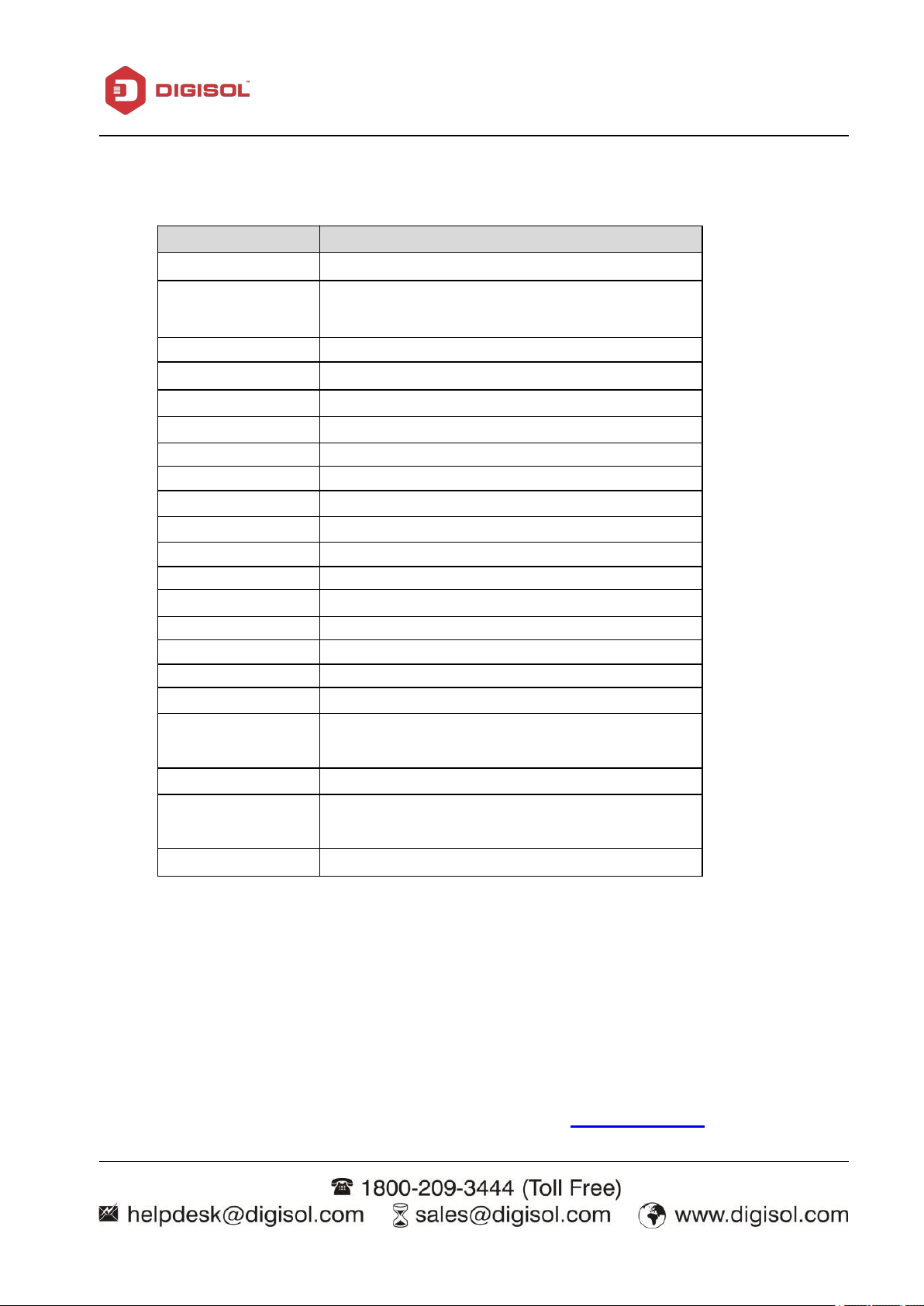
Appendix 2.Technical parameters
Feature
DG-SR4508
Video Compression
H.264
Max No. Of
Cameras Added
8
Hard disk port
2*SATA
Max. Capacity
Max Capacity: 8TB
Recording Mode
Continuous/ Manual/ Schedule/ Motion Detection
Recording Search
Date/ Time-based
Recording storage
Hard Disk, Network
Backup mode
Network, USB flash/ HDD
Video output
1 HDMI, 1VGA
Audio Input
1*RCA
Audio output
1*RCA
Network port
RJ45 10M/100/1000Mbps
USB port
2* USB2.0 ports
Export File format
AVI, DAT
Event Trigger Action
Email/ FTP
Log
Yes
Remote Management
Yes
Supported Protocols
IPv4, TCP, UDP, DHCP, NTP, DNS, DDNS,
SMTP, FTP, HTTP, UPnP, RTSP, PPPoE
Security
Multi-level User Management/ Event Log
Concurrent
Recording
8
Power Rating
12V DC/ 2A
NVR User Manual
This product comes with two Years warranty. For further details about warranty policy and Product
Registration, please visit support section of www.digisol.com
 Loading...