

Page 1
DG-SC7369-18
2MP 18x SPEED DOME IP CAMERA
User Manual
V1.0
2017-11-16
As our products undergo continuous development the specifications are subject to change without prior notice
Page 2

DG-SC7369-18 User Manual
2
COPYRIGHT
Copyright 2017 by Digisol Systems Ltd. All rights reserved.Company has an ongoing policy of
upgrading its products and it may be possible that information in this document is not up-to-date.
Please check with your local distributors for latest information. No part of this document can be
copied or reproduced in any form without written consent from the company.
Trademark
DIGISOLTMis a trademark of Digisol Systems Ltd. All other trademarks are the property of the
respective manufacturers.
Page 3

DG-SC7369-18 User Manual
3
INDEX
1. Product Introduction...............................................................................................................................................5
1-1 Introduction and safety information............................................................................................................... 5
1-2 Safety Information.......................................................................................................................................... 6
1-3 System Requirements......................................................................................................................................6
1-4 Package Contents............................................................................................................................................ 6
2 Using Network IP Camera by Web Interface......................................................................................................7
2-1 Locate the IP address of Network IP Camera.................................................................................................7
2-2 Connect to IP camera’s Web User Interface................................................................................................... 7
Speed Dome IPC Menu.......................................................................................................................................13
2-3 Log...............................................................................................................................................................14
2-4 Config............................................................................................................................................................14
2-4a Base Config.........................................................................................................................................14
2-4a-1 System..............................................................................................................................................14
2-4a-2 Network............................................................................................................................................... 16
2-4a-3 AV.........................................................................................................................................................17
2-4a-4 Image....................................................................................................................................................18
2-4a-5 Safe...................................................................................................................................................... 20
2-4b Advance Config...................................................................................................................................... 20
2-4b-1 Network............................................................................................................................................... 20
2-4b-2 Event...................................................................................................................................................21
2-4b-3 Store....................................................................................................................................................21
2-4b-4 PTZ.....................................................................................................................................................22
2-4b-5 Status..................................................................................................................................................23
3 PTZ Commands to control via NVR...................................................................................................................24
4. Using CMS software............................................................................................................................................25
4-1 Installing CMS Software.............................................................................................................................. 25
4-2 Getting familiar with CMS Software............................................................................................................28
4-3 CMS Configuration.......................................................................................................................................31
4-3-1 CMS Operation Main Menu..............................................................................................................31
4-3-2 Device display area............................................................................................................................31
4-3-3 Operation area................................................................................................................................... 31
4-3-4 Time................................................................................................................................................... 31
4-3-5 Video disk status area........................................................................................................................ 32
4-3-6 PTZ.................................................................................................................................................... 32
4-3-7 Operation log..................................................................................................................................... 32
4-3-8 Menu Area......................................................................................................................................... 32
4-3-8-1 PTZ control........................................................................................................................................ 34
4-3-8-2 Color Setting...................................................................................................................................... 35
Page 4

DG-SC7369-18 User Manual
4
4-3-8-3 System................................................................................................................................................ 35
4-3-8-3 a) Device Manager............................................................................................................................. 35
4-3-8-3 b) Local Config.................................................................................................................................. 39
4-3-8-3 c) Remote Config............................................................................................................................... 41
4-3-8-3 d) Account.......................................................................................................................................... 41
4-3-8-3 e) Local Log....................................................................................................................................... 43
4-3-9 Playback.............................................................................................................................................43
4-3-10 Advance........................................................................................................................................... 44
4-3-11 Logout..............................................................................................................................................44
5 Appendix..................................................................................................................................................................45
5-1 Specifications................................................................................................................................................45
5-2 Troubleshooting............................................................................................................................................ 46
5-3 Glossary........................................................................................................................................................ 47
Page 5

DG-SC7369-18 User Manual
5
1. Product Introduction
1-1 Introduction and safety information
Thank you for purchasing DIGISOL IP cameras!!
DIGISOL Speed Dome PTZ IP Camera HD Resolution with IR LED and IR-cut Filter. This camera offers
the latest compression technology with a CMOS sensor & a real time image processing hardware. With its
high performance H.264 compression, users can stream high quality video at low bandwidth and storage
capacity requirements.
It has IR LED for visibility under no light condition. The IR cut filter offers a true image quality during
day/night operations.
This IP camera supports Digital WDR, a software-based technique that enables the camera to produce clearer
images in less than ideal lighting conditions. Digital-WDR balances the contrast of light and shadow to
improve visibility in dark areas within a scene.
Other features of this network IP Camera includes:
2MP 1/2.8" sensor
Supports 1080P Resolution
Supports H.264 Compression
8 LED lamps Up to 120m
Day/ Night Mode (Auto ICR)
Support DWDR
18x Optical Zoom
IP66 Compliant
Page 6

DG-SC7369-18 User Manual
6
1-2 Safety Information
In order to keep the safety of users and your properties, please follow the safety instructions as
mentioned below. The warranty will become void if you disobey these safety instructions.
This Network IP Camera is sophisticated electronic device; DO NOT drop it from a height.
DO NOT place this IP Camera at hot / humid places, and avoid direct sunlight.
Accessories of this IP Camera like power supply are dangerous to small children. KEEP THIS
IP CAMERA OUT OF REACH OF CHILDREN.
If you want to use this IP Camera at any place that may be spilled by water or dirt, a secure and
water-proof camera housing is required.
DO NOT pull any cord that is connected to this IP Camera by force.
The IP Camera will get heated up when used for a long time. (This is normal and is not a
malfunction). DO NOT put this IP camera on paper, cloth, or other flammable materials.
If the IP Camera falls into water when powered, DO NOT attempt to retrieve it back yourself!
Find a qualified electrical technician for help.
1-3 System Requirements
Windows XP, Vista or Win 7 operating system (both 32 or 64 bits version)
2GB of system memory
1GB of Display card memory
20GB of available hard disk space on system drive
1-4 Package Contents
Before you start using this IP camera, please check if there’s anything missing in the package, and
contact your dealer of purchase to claim for missing items:
DG-SC7369-18 Speed Dome Camera
Quick Installation Guide
Installation Guide CD (includes user manual, QIG & CMS software)
Power Adapter 12V 4A
Mounting Accessories
Page 7
DG-SC7369-18 User Manual
7
2 Using Network IP Camera by Web Interface
2-1 Locate the IP address of Network IP Camera
You must know the IP address of IP Camera before you can connect to it.
By default the IP camera is on Static IP & default IP address is 192.168.1.160. Connect the camera
to router or a switch & set it on DHCP.
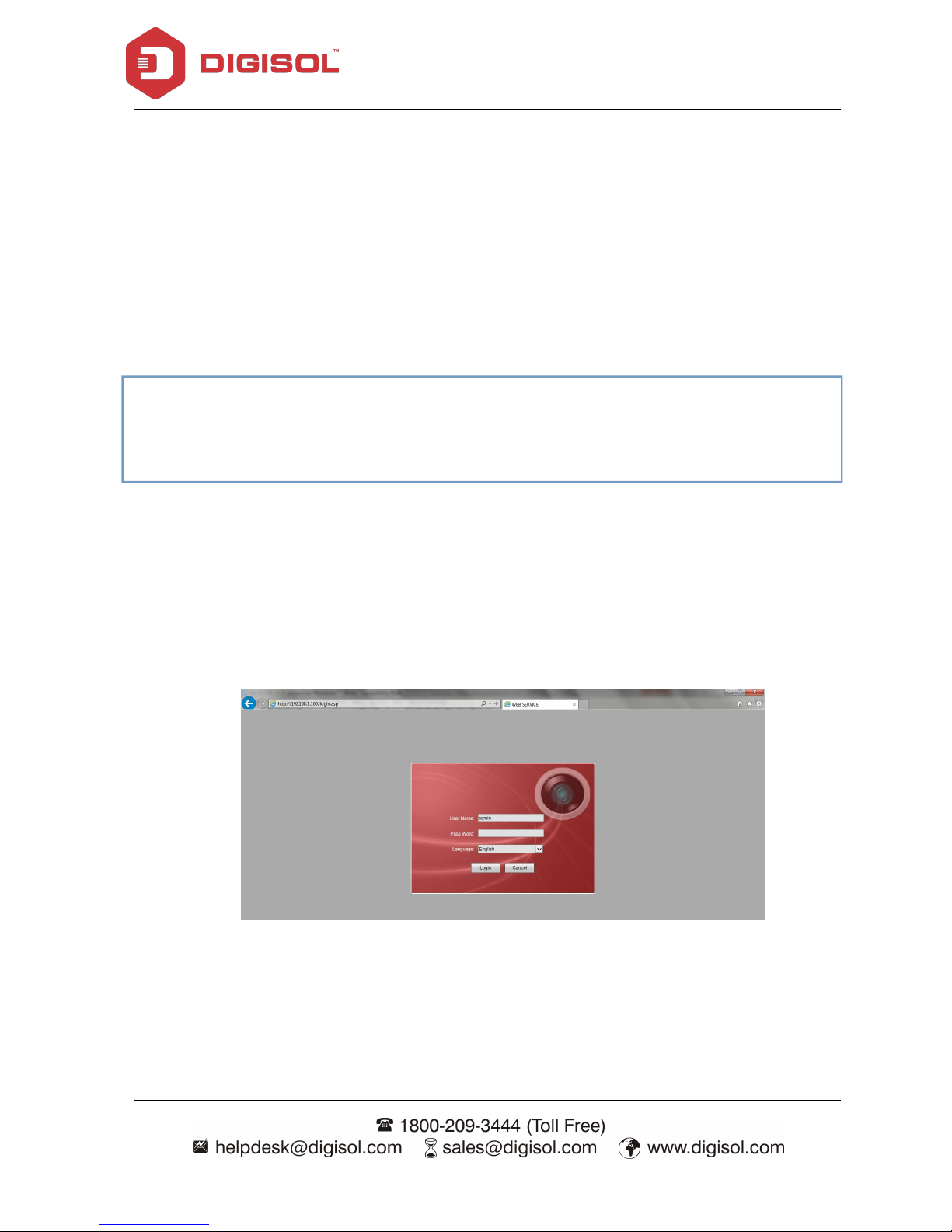
2-2 Connect to IP camera’s Web User Interface
When you know the IP address of IP camera, you can connect to it by Internet Explorer web
browser by entering its IP address in the address bar. The user login screen will appear when you get
connected:
IP Camera’s administrator username and password are admin & 12345 by default. Click ‘OK’
button or press ‘ENTER’ key on your keyboard when you finish entering username and password.
Note:
If you have several network connections, such as "Wireless Function”, disable the
"Wireless functions" or other network connections that are not connected to the IP camera, as
utility may fail to search IP camera.
Page 8
DG-SC7369-18 User Manual
8
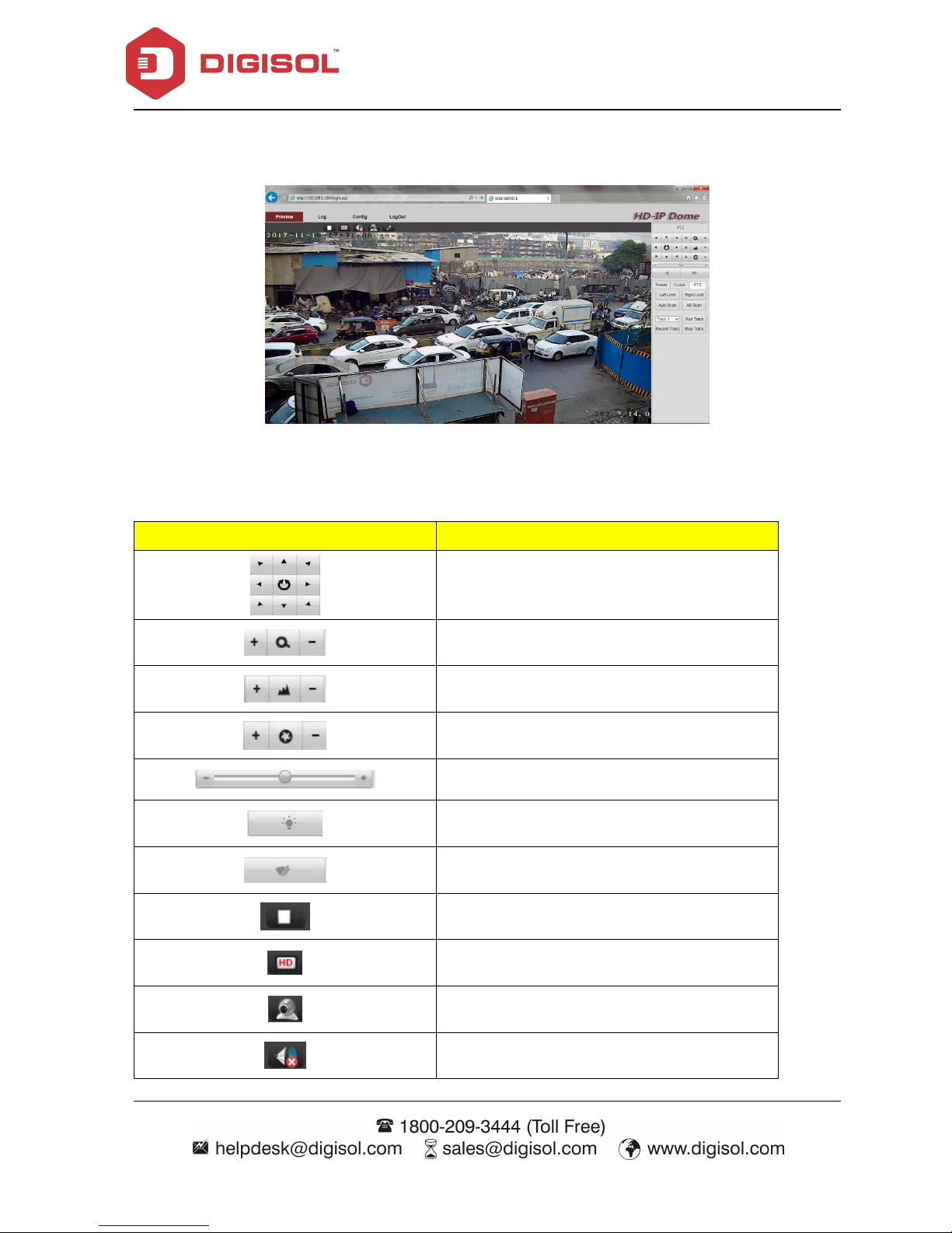
Click OK to display the camera video.
There are various controls on the web page; here is the description of every control item:
Icon
Illustration
To control horizontal/ vertical movement of the
camera & open/close automatic scan
zoom
focus
iris
PTZ Speed Adjustment
Open/ Close Lamp light
Wipers (optional)
Close/open video
Main/Sub code stream
3D function switch
Sound Monitor (Optional)
Page 9
DG-SC7369-18 User Manual
9
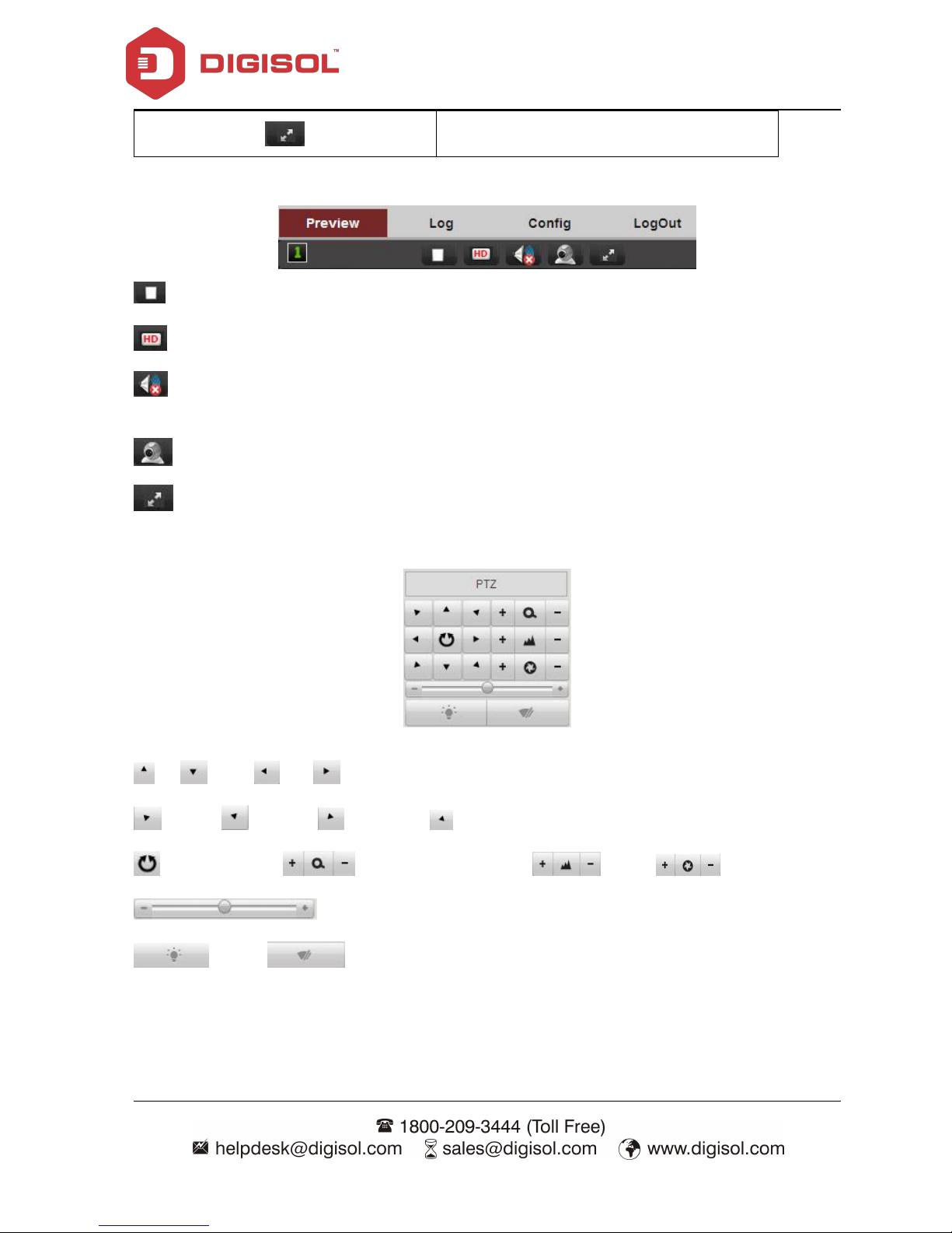
Full screen
Preview Tab:
To close/open video, by default it is opened.
To modify Mainstream/ Substream, by default default is Mainstream.
For camera with audio function, by default is mute.
3D function switch, by default is disabled.
Switch to Full screen, by default is disabled.
PTZ button
Up; Down; Left; Right;
Left top; Right top; Left down; Right down;
Automatic scan; Zoom in and zoom out ; Focus; ;Aperture;
Pan&tilt speed;
IR light; Wipers(optional)
Page 10
DG-SC7369-18 User Manual
10
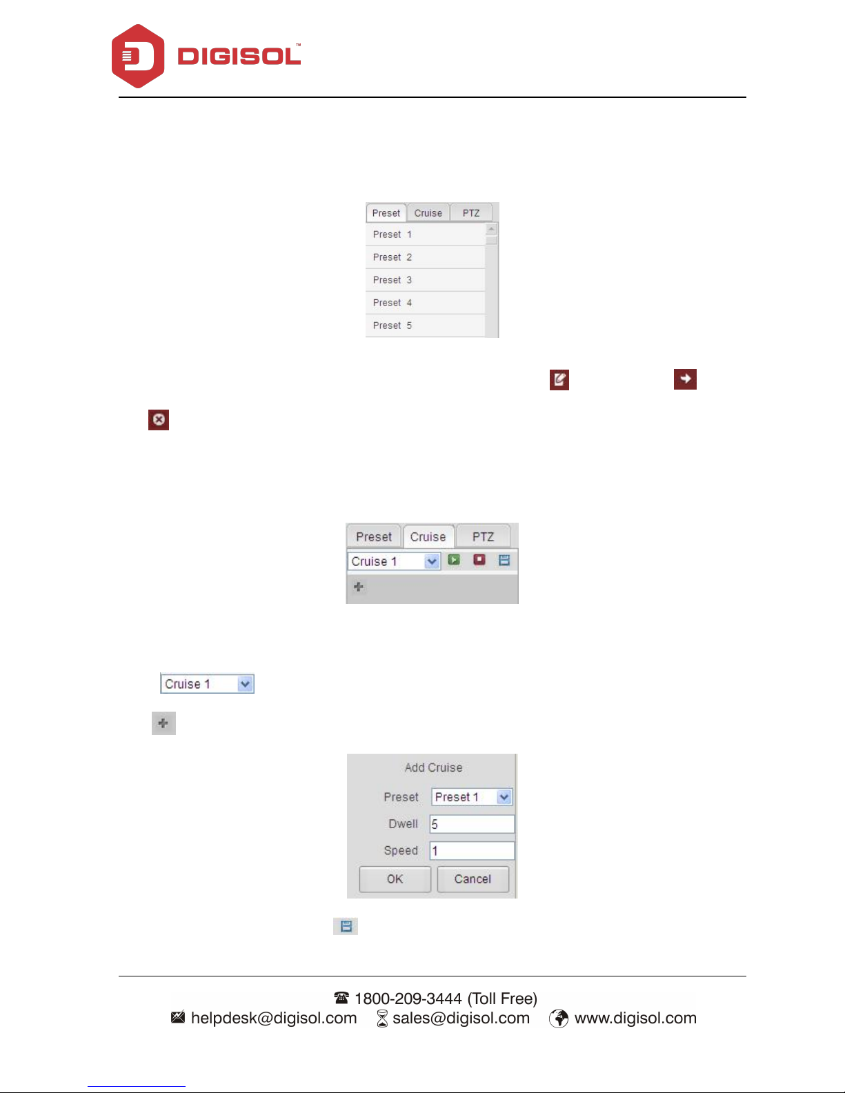
Preset setup
a) Setting Presets
To configure preset, turn the PTZ cam to desired position and click to setup, click to call,
click to delete
b) Setting Cruise
You can configure 8 cruise on this IPC & each cruise supports 16 presets each.
Click
Click to add the desired preset, set the cruise time/ speed & click OK.
After adding desired preset, click to save the cruise, as shown below
Page 11
DG-SC7369-18 User Manual
11
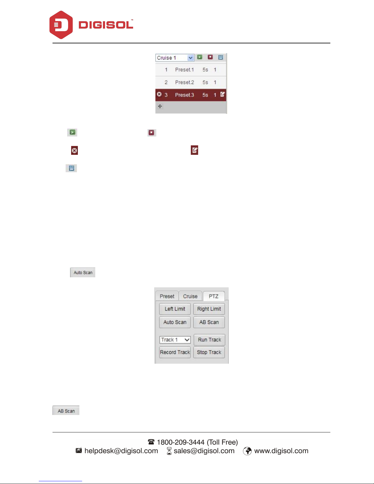
Click to call this cruise, click to stop the cruise
Click to delete the preset in the cruise, click to edit the preset in the cruise, after modifying
click to save.
c) Scan settings
Support AB Scan, Auto Scan & Pattern Scan (Track) as shown below:-
Auto Scan
Click for 360 degree pan, click again to stop;
AB Scan
You can set two points & configure this Speed Dome IPC to scan these two points using AB Scan
option.
Page 12

DG-SC7369-18 User Manual
12
Point the camera to desired location & click to set up the left point for scan
Point the camera to desired location & click to set up the right point for scan
Then click to start the scan between Left & Right position; click it again to stop
scanning
Pattern scan
This IPC supports 4 pattern scan.
Click to setup the track route (setting the pattern scan) & then click
to stop recording;
Click to start the pattern of patrol scan, click it again to stop scanning;
You can set up to 4 points in each pattern for less than 3min & it is not recommended to set this IPC
on continuous pattern scan as it may effect the IPC chipset processor.
Page 13
DG-SC7369-18 User Manual
13
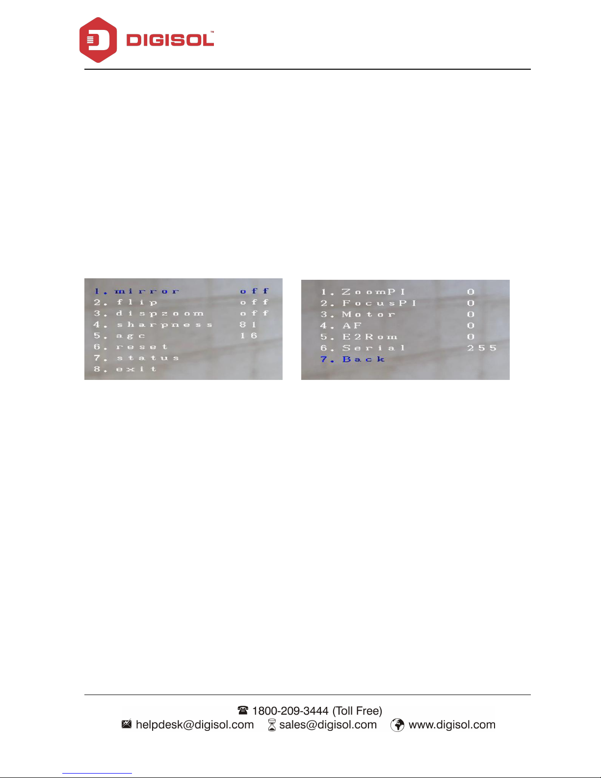
Speed Dome IPC Menu:
Call preset 95 to enter the Menu of speed dome IPC as shown below:-
1. Mirror: To switch ON/ OFF mirror image of IPC. By default it’s OFF
2. Flip: To switch ON/ OFF the flip mode of IPC. By default it’s OFF
3. Dispzoom: To switch ON/ OFF the display zoom. By default it’s OFF
4. Sharpness: To adjust the sharpness of IPC. By default it’s 80
5. AGC: To adjust the automatic gain of IPC. By default it’s 16
6. Reset: To restore Menu parameters to factory default
7. Status:
8. Exit: To exit the IPC Menu
Menu Option Status Option
Page 14
DG-SC7369-18 User Manual
14
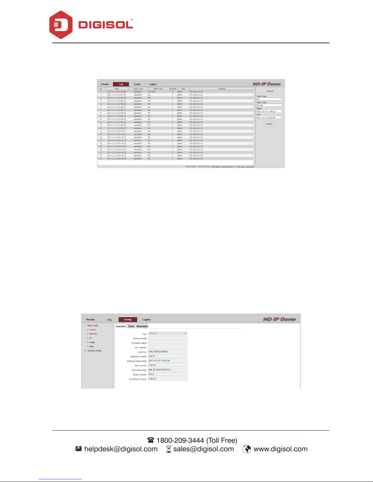
2-3 Log
Under this tab, you can view the logs of IPC as shown below:
2-4 Config
You can configure advanced parameters of IPC under this tab.
2-4a Base Config
Following are the sub menus under this ‘Base Config’ option.
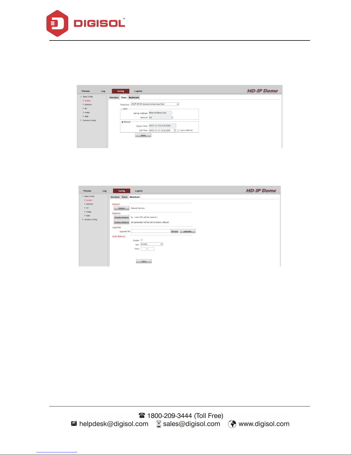
2-4a-1 System
Under System, there are different menus like Version, Time & Maintain available as displayed
below:-
Version: You can view the IPC information like Software version, Serial No, etc under this tab.
Page 15
DG-SC7369-18 User Manual
15
Time: You can configure Time Settings i.e) Setting time Manually OR to sync the IPC time with
NTP server under this tab.
Maintain:You can Reboot, Restore the IPC settings by reserving the IP Address / User details,
Restore the settings to factory default, Auto Reboot OR upgrade the IPC firmware under this tab.
Page 16

DG-SC7369-18 User Manual
16
2-4a-2 Network
Under Network, there are different menus like Eth & Service available as displayed below:-
ETH: You can modify the IP address details of camera under this tab.
Services: You can modify IPC ports like RTSP, HTTP, RTMP under this tab.
Page 17

DG-SC7369-18 User Manual
17
2-4a-3 AV
You can configure Video parameters of IP camera under this tab.
If you click on Advance, it will display the below screen:
Here you can set the parameters like bit rate, stream type, quality, etc.
Page 18

DG-SC7369-18 User Manual
18
2-4a-4 Image
You can configure Image Settings under this Option. There are different sub menus
available under this tab as described below:-
Display: You can configure color settings like brightness, contrast, saturation, etc under
this option.
OSD: The overlay Text, Bit Rate, Time information can be configured under this tab to be
displayed on the screen
Page 19

DG-SC7369-18 User Manual
19
Video mask: You can define 4 privacy mask zones under this tab.
ICR: You can set the IR LED settings under this tab.
Page 20

DG-SC7369-18 User Manual
20
2-4a-5 Safe
You can modify the administrator password of IPC under this tab.
2-4b Advance Config
Under this tab, you can configure advanced parameters on this IP camera.
2-4b-1 Network
The following options are available in ‘Network’ tab under ‘Advance Config’:
You can configure other features like PPPoE, DDNS, FTP, EMAIL, UPnP settings under this tab.
Page 21

DG-SC7369-18 User Manual
21
2-4b-2 Event
You can configure Motion Detection Settings under this tab.
Motion detect: You can set the area for Motion detection & also define a desired
Schedule or enable it for 24x7.
Hide detect: You can set a mask on IPC for specific schedule & integrate it with Email, FTP.
IO alarm: This feature is not supported
Abnormal: Alarm is triggered if no HDD, the HDD is full, HDD is wrong, no internet and IP
address conflict is detected
Alarm snap: It can be set to capture the photo or not when action alarm, and the interval time can
be set.
2-4b-3 Store
This option is not supported for this IPC.
Page 22

DG-SC7369-18 User Manual
22
2-4b-4 PTZ
You can set the PTZ settings under this tab. There are three sub menus under this tab.
PTZ: PTZ parameters are displayed in screen below.
Task: You can set the schedule for respective PTZ action like AB scan, Cruise, Auto Scan, Preset or
Track under this tab.
Page 23

DG-SC7369-18 User Manual
23
Park Action: You can set the respective Idle Action from drop down menu for defined Park time
e.g) Cruise2 is selected as Idle Action for Park time 15sec that means if the IPC is idle for 15sec, it
will automatically start Cruise2.
2-4b-5 Status
Status menu shows hardware, storage (for supported camera), channel status & bit rate of
speed dome camera.
Hardware Status: Display hardware configuration of speed dome camera .
Recode: Display record state of SD card supported IPC
Channel Status: Display the working status of speed dome camera.
Channel Stream:Display code stream information of speed dome camera.
Page 24

DG-SC7369-18 User Manual
24
3 PTZ commands to control via NVR
This PTZ IP Dome camera supports 8 Cruise with 16 Presets in each cruise. You can use Web GUI
of IP Camera to control cruise setting & to load the menu of this IP camera.
It supports predefined auto focus which is auto adjusted when the image is Zoomed In or Zoomed
Out. This IPC supports up to 128 presets.
There are some predefined presets which are listed in table as given below to control this IPC using
NVR:-
No.
Function
Operation
1
Record Track 1
Setup preset 41
Start Track 1
Call preset 41
Record Track 2
Setup preset 42
Start track 2
Call preset 42
Record Track 3
Setup preset 43
Start Track 3
Call preset 43
Record Track 4
Setup preset 44
Start Track 4
Call preset 44
2
Setup Left limit
Setup/ Call preset 46
Setup Right limit
Setup/ Call preset 47
A to B scanning
Setup/ Call preset 48
3
360degree scanning
Setup/ Call preset 49
4
Pan& Tilt speed 1 (30°/s)
Setup/ Call preset 50
Pan& Tilt speed 2 (60°/s)
Setup/ Call preset 51
Pan& Tilt speed 3 (80°/s)
Setup/ Call preset 52
Pan& Tilt speed 4 (100°/s)
Setup/ Call preset 53
Pan& Tilt speed 5 (120°/s
Setup/ Call preset 54
5
Scanning speed 1 (30°/s)
Setup/ Call preset 60
Scanning speed 2 (50°/s)
Setup/ Call preset 61
Scanning speed 3 (60°/s)
Setup/ Call preset 62
Scanning speed 4 (80°/s)
Setup/ Call preset 63
Scanning speed 5 (100°/s)
Setup/ Call preset 64
Page 25

DG-SC7369-18 User Manual
25
4. Using CMS software
4-1 Installing CMS Software
The CMS software provides various functions like video recording. After this software is installed,
you can use your IP camera to safeguard your property. Please follow the below mentioned
instructions to install the CMS software.
1. Please insert the Installation Guide CD supplied in the product package.
2. Run the ‘General_Digisol_CMS Setup.exe’ file program. The wizard as shown below will
appear.
Page 26

DG-SC7369-18 User Manual
26
3. The screen as shown below will appear. Click ‘Next’ to continue.
4. Click Next & browse the location.
Page 27

DG-SC7369-18 User Manual
27
5. Proceed by clicking Next to finish the installation.
6. Please wait while installation is being performed. This may take few minutes, please be patient.
7. A new icon will appear on your computer’s desktop, you can double click on it to start CMS.
Page 28

DG-SC7369-18 User Manual
28
4-2 Getting familiar with CMS Software
To start CMS, double click CMS icon on your computer’s desktop:
Or click ‘Start’ button of Windows, and select ‘All Programs’ -> ‘CMS ->Launch CMS’
CMS login screen will appear as shown below:
Page 29

DG-SC7369-18 User Manual
29
Default user ID is ‘admin’ and default password is none (leave it blank), click ‘OK’.
The main window of CMS will appear:
The CMS Main Menu options are described as below:-
Main Menu
Sub Menu
Function
Preview
You can view the IP camera live video, touring &
switching between different IP cameras, Open & Close
IP camera Preview.
PTZ
To Pan/ Tilt, control Zoom, Focus, define presets & IP
camera Tour for supported IP cameras.
Color
Set brightness, contrast, saturation and hue for
respective camera Video.
System
Device Manager
You can Add Zone, Edit, Delete the respective IP
camera, Import- Export the existing configuration, Test
connection under this option.
Local Config
Under this option, you can set the record plan, Alarm
setting for respective camera, CMS Version Info is
Page 30

DG-SC7369-18 User Manual
30
displayed.
Remote Config
You can manage the Web GUI parameters of respective
camera using this tab.
Account
You can create user privileges for CMS software control
under this tab.
Local Log
All type of Logs including System & Operational will
be displayed under this tab. You can search/ export the
logs based on Date/ time search.
Playback
Remote Playback
To play the recordings stored on NVR
Local Playback
To play the recordings stored on local PC drive.
Advance
Decoder
Set DVR and decoder
Tour
To define Tour based on IP cameras Preview
Logout
To log off the CMS session
Page 31

DG-SC7369-18 User Manual
31
4-3 CMS Configuration
4-3-1 CMS Operation Main Menu
4-3-2 Device display area
In this area, you can preview live video by device and super account administrator setting, click
device name or channel group to change channels.
4-3-3 Operation area
You can preview live video, setup parameters of system configuration and video search in this area.
4-3-4 Time
Displays Date, time & CPU Usage
Page 32

DG-SC7369-18 User Manual
32
4-3-5 Video disk status area
It displays disk space of defined path where the videos are stored locally.
4-3-6 PTZ
Displays PT Controls & Settings
4-3-7 Operation log
It displays operation information in this window.
4-3-8 Menu Area
To configure advanced settings in CMS software.
Menu Configuration
Item
Description
Click this button to display video from IP cameras in full screen
mode. All control buttons will be hidden, only IP camera’s video
will be displayed. To exit full screen mode, right click on IP
camera video & select ‘Main Desktop’.
/ / /
/ /
/
CMS supports 1/ 4/ 9/ 16/ 25/ 36/ 64 cameras split views. The
video from IP camera will display in split screen display cells,
and you can view up to 64 IP cameras at the same time. Click the
button to select the number of IP cameras you wish to view on
display. If the number of IP cameras is less than the number of
split screens, unused display cell will be displayed blank to
indicate it’s not been connected to any IP camera.
Page 33

DG-SC7369-18 User Manual
33
Right Click Menu
If you right click on Video display, it will prompt the window as shown below:-
Close window: close the current video
Close all window: close all the current videos
Audio: If you click this option, audio will be enabled for selected live video screen
Local record: Click this option to record the selected channel at path defined under Local
Config>>Base Config option
Zoomed: Click this option to digitally zoom the desired video portion.
Snapshot: Click this option to take a snap of selected channel & store at path defined under Local
Config>>Base Config option
Start Talk: For Supported IP camera
Device Config: Click this option to manage the device config tab of IP camera Web Interface
Color Setting: It will display the color setting parameter
View Full: To view the IP camera video on full screen mode
Page 34

DG-SC7369-18 User Manual
34
4-3-8-1 PTZ control
You can Pan/ Tilt, Zoom, Focus, set preset and tour for supported IP cameras using this PTZ
Controls in CMS software.
Item
Description
Pan / Tilt control
Click the direction arrow to control camera’s pan / tilt.
Pan / Tilt speed
Drag the slide bar to adjust the pan / tilt speed when you click
pan / tilt control arrow.
Optical zoom control. Click + or - to control zoom level. This
function is only available for supported cameras.
Click + or – to adjust the focus. This function is only available
for supported cameras.
Click + or – to adjust the Iris. This function is only available for
supported cameras.
Click or to set the camera on auto pan. This function is
only available for supported cameras.
Click + or - to add/ remove presets of camera. Click on to
point the camera to defined preset location.
Page 35

DG-SC7369-18 User Manual
35
Click or to start/ stop the desired Tour & click on
to edit the defined tour.
4-3-8-2 Color Setting
You can adjust the brightness, Contrast, Saturation & Hue settings under this option to get the
desired Image quality. Click default to reset the configured image settings.
4-3-8-3 System
You can configure advance settings under this tab. There are various sub menus like Device
Manager, Local Config, Remote Config, Account & Local Log.
4-3-8-3 a) Device Manager
If you click Device Manager button, it will display the following screen:
Page 36

DG-SC7369-18 User Manual
36
Click button to add the Zone as shown below:
Once you define the Zone, it will be listed under Zone List.
Click icon & click on IP Search button to discover the IP Cameras connected in Local LAN.
Page 37

DG-SC7369-18 User Manual
37
Select the desired IP camera from the list & enter the details as shown below:-
Device Name: Give any Name.
Domain: If you are having any DDNS account of remote IP camera, you can specify under this
field.
IP Address: You can enter Local IP or Static IP (for remote viewing) in this field.
Port: Specify the Camera port number.
User Name: Enter the Camera User ID
Password: Enter the Camera Password
Click "OK" once the settings are configured.
Then the camera will be listed on LHS of Main Window as shown below:
Page 38

DG-SC7369-18 User Manual
38
Double click on it to connect the IP camera in CMS software.
Click icon to edit the settings of Added Camera in CMS software.
Click icon to delete the added camera in CMS software.
Note: Please make sure the device is disconnected before modifying or deleting it.
Click icon to Import/ Export the CMS settings.
Page 39

DG-SC7369-18 User Manual
39
Click icon to test the connectivity of added camera.
4-3-8-3 b) Local Config
If you click Local config button, it will display the following window:
Under Base Config, you can configure the settings as shown above.
You can set the Recording Mode for respective cameras along with the Storage path & overwrite
option under Local Config tab.
Page 40

DG-SC7369-18 User Manual
40
You can check the CMS software information under Version tab:
Page 41

DG-SC7369-18 User Manual
41
4-3-8-3 c) Remote Config
Using this tab you can manage the Web GUI of an IP camera from CMS software.
4-3-8-3 d) Account
In this menu, you can configure IP camera’s login account. There are two kinds of accounts:
Administrator: Can view IP camera’s video and make changes of camera setting
User: Can view IP camera’s video and see settings, but can’t make any change.
There can be multiple users, but only one administrator is allowed, and you can’t change
administrator’s user name (it will always be ‘administrator’)
Page 42

DG-SC7369-18 User Manual
42
Add/ delete group and set group privileges as shown above.
User Account
You can Add/ Delete user account & modify user password under this menu.
Page 43

DG-SC7369-18 User Manual
43
4-3-8-3 e) Local Log
All type of Logs including System & Operational will be displayed under this tab. You can search/
export the logs based on Date/ time search.
4-3-9 Playback
There are 2 playback modes---Remote playback and Local playback.
Remote playback: To pull the recordings of NVR.
Local playback: To pull the recordings stored on local drive.
You can select the desired camera Channel depending on Date/ Time to play the desired recordings.
You can playback 4 cameras at a time under this tab.
You can also download/ backup the recordings pulled in CMS software.
Page 44

DG-SC7369-18 User Manual
44
4-3-10 Advance
There are various sub menus like Decoder, Map, Tour & Task Config under this tab.
4-3-11 Logout
To log off the CMS software.
Page 45

DG-SC7369-18 User Manual
45
5 Appendix
5-1 Specifications
Feature
DG-SC7369-18
Sensor
1/2.8" CMOS Sensor
Lens
Vari-Focal
Focal Length
5mm~90mm
Min Illumination
0.01Lux with AGC ON
Max Resolution
1920 x 1080 (1080P) @ 25fps
IR LED
8 PCS IR array LED, Up to 120m distance
IR-CUT Filter
Yes
Rotation Range
Pan:0°~360°
Tilt: 0°~90°
Presets Supported
128
Video compression
H.264
Protocol
TCP/IP, HTTP, DHCP, DNS, DDNS, PPPoE, SMTP, NTP
Interface
1*10/100Mbps RJ45 port
Temperature
0°C~50°C
Humidity
10%-90% RH
Power Supply
12VDC
IP66 compliant
Yes
Page 46

DG-SC7369-18 User Manual
46
5-2 Troubleshooting
Please don’t panic when you find this IP camera is not working properly. Before you send this IP
camera back to us, you can do some simple checks to save your time:
Problem description
Possible solution(s)
Cannot connect to IP Camera
Please check the IP address of IP Camera again.
Please make sure the network cable is correctly connected to
your local area network.
Please make sure power cable is correctly connected to IP
Camera.
Please make sure IP Camera is switched on (the LED lights
on IP Camera will light up).
No IP Camera found
‘Auto search’ function only works on IP Cameras located on
local area network.
No image
If the place where IP camera is installed is too dark, try to add
some lights when possible.
Check if there’s anything covering the lens.
Page 47

DG-SC7369-18 User Manual
47
5-3 Glossary
H.264: H.264 is the latest compression technology that significantly reduces the file size of
high-quality video images. Offers higher video resolution than Motion JPEG or MPEG-4 at the
same bit rate and bandwidth, or the same quality video at a lower bit rate.
PPPoE (Point-to-Point Protocol over Ethernet): Is a network protocol for encapsulating
Point-to-Point Protocol (PPP) frames inside Ethernet frames.
TCP / IP (Transmission Control Protocol/ Internet Protocol): TCP is used along with the Internet
Protocol (IP) to transmit data as packets between computers over the network. TCP is a
connection-oriented protocol, which means that a connection is established between the two
end-points and is maintained until the data has been successfully exchanged between the
communicating applications.
DDNS (Dynamic DNS): Used to create a fixed domain name for dynamic internet IP address. A
domain name is a meaningful and easy-to-remember name for an Internet address. Normally used
when the ISP has provided you with dynamic internet IP address to access the camera remotely.
SMTP (Simple Mail Transfer Protocol): SMTP is used for sending and receiving e-mail. SMTP
authentication is an extension of SMTP, whereby the client is required to log into the mail server
before or during the sending of email. It can be used to allow legitimate users to send email while
denying the service to unauthorized users, such as spammers.
UPnP (Universal Plug & Play): A set of computer network protocols that allow the automatic
peer-to-peer detection of devices on the network. Allows the discovery of UPnP- enabled devices in
a network environment.
RTSP (Real Time Streaming protocol): RTSP is a control protocol for Internet streaming of audio
and video. Mostly used for remote viewing of live or stored security camera video over the Internet.
RTSP can be considered as a “remote control” for controlling the media stream delivered by a media
server. RTSP servers typically use RTP as the protocol for the actual transport of audio/video data.
CMOS Sensor (Complimentary metal-oxide semiconductor): Is an image sensor available in
manyIP network cameras with less circuitry hence consumes less power, produces higher frame rate
& is less costly as compared to CCD sensors.
Frame Rate: The frame rate is used to describe the frequency at which a video stream is updated is
measured in frames per second (fps). If you want more accurate video then the frame rate should be
kept high. Lower the frame rate, lesser the image details.
Page 48

DG-SC7369-18 User Manual
48
IP filtering: The IP camera can either white list or blacklist an IP address. This restricts
unauthorized access to the IP camera.
Infrared (IR) cut-off filters: They are used with color CCD or CMOS imagers to produce accurate
color images. An IR cut-off filter blocks the transmission of the infrared while passing the visible.
This can be done with two optical techniques: absorption or reflection. Absorptive filters are made
with special optical glass that absorbs near infrared radiation. Reflection type filters are short-pass
interference filters that reflect infrared light with high efficiency.
Day/Night function: This IP camera has IR LED for better visibility under no light
environment. If the environment light is not sufficient enough to view the camera then the IR LED’s
are triggered automatically for better visibility.
Digital WDR: It is a software-based technique that enables the camera to produce clearer images
in less than ideal lighting conditions. D-WDR balances the contrast of light and shadow to improve
visibility in dark areas within a scene.
Weatherproof Housing: This IP camera complies with IP66 standard thus protecting it from dust
and direct sprays from all directions (limited ingress permitted).
This product comes with Two Years warranty. For further details about warranty policy and Product
Registration, please visit support section of www.digisol.com
 Loading...