

Page 1
DG-SC2100 /
DG-SC2100W
IP Surveillance Camera
User Manual
V1.3
2012-12-06
As our products undergo continuous development the specifications are subject to change without prior notice.
Page 2

DG-SC2100/DG-SC2100W User Manual
2
COPYRIGHT
Copyright ©2012 by this company. All rights reserved. No part of this publication
may be reproduced, transmitted, transcribed, stored in a retrieval system, or translated
into any language or computer language, in any form or by any means, electronic,
mechanical, magnetic, optical, chemical, manual or otherwise, without the prior
written permission of this company.
This company makes no representations or warranties, either expressed or implied,
with respect to the contents hereof and specifically disclaims any warranties,
merchantability or fitness for any particular purpose. Any software described in this
manual is sold or licensed "as is". Should the programs prove defective following
their purchase, the buyer (and not this company, its distributor, or its dealer) assumes
the entire cost of all necessary servicing, repair, and any incidental or consequential
damages resulting from any defect in the software. Further, this company reserves the
right to revise this publication and to make changes from time to time in the contents
thereof without obligation to notify any person of such revision or changes.
Trademarks:
DIGISOL™ is a trademark of Smartlink Network Systems Ltd. All other trademarks
are the property of the respective manufacturers.
Safety
This equipment is designed with the utmost care for the safety of those who install
and use it. However, special attention must be paid to the dangers of electric shock
and static electricity when working with electrical equipment. All guidelines of this
and of the computer manufacturer must therefore be allowed at all times to ensure the
safe use of the equipment.
Page 3

DG-SC2100/DG-SC2100W User Manual
3
INDEX
1 Product Information.................................................................................................................5
1.1 Product Introduction ...........................................................................................................5
1.2 Product Features..................................................................................................................6
1.3 Preparation Before Installation ...........................................................................................7
1.4 Hardware Description .........................................................................................................8
1.5 Camera Installation...........................................................................................................11
1.6 Locate the IP Address of this IP Camera........................................................................... 12
1.7 Using Camera Admin Software to Locate Camera...........................................................16
1.8 Log Onto Web Management Interface..............................................................................22
2 Using Web Management Interface .....................................................................................25
2.1 Camera Settings................................................................................................................25
2.1.1 About....................................................................................................................28
2.2 LAN ..................................................................................................................................29
2.2.1 IP address............................................................................................................29
2.2.2 RTSP....................................................................................................................31
2.2.3 Dynamic DNS......................................................................................................32
2.2.4 UPnP....................................................................................................................33
2.2.5 LoginFree.............................................................................................................35
2.3 WLAN Parameters............................................................................................................36
2.4 Vide o.................................................................................................................................41
2.4.1 Dual Mode...........................................................................................................42
2.4.2 MPEG4.................................................................................................................42
2.4.3 MJPEG.................................................................................................................43
2.5 Email & FTP.....................................................................................................................45
2.5.1 Email Settings.....................................................................................................46
2.5.2 FTP Settings........................................................................................................47
2.6 Motion Detection ..............................................................................................................49
2.6.1 Basic Settings .....................................................................................................49
2.6.2 Set up Motion Detection Region ......................................................................51
2.7 Schedule............................................................................................................................53
2.8 System...............................................................................................................................55
2.8.1 Camera Information ...........................................................................................56
2.8.2 Date / Time Setting.............................................................................................57
2.8.3 Utilities..................................................................................................................58
2.9 Status..................................................................................................................... ............59
2.10 Account ...........................................................................................................................60
2.11 Log..................................................................................................................................62
3 Using SKYROS Surveillance Manager Software............................................................63
3.1 Installing SKYROS Surveillance Manager Software .......................................................63
3.2 Using SKYROS Surveillance Manager software..............................................................67
Page 4

DG-SC2100/DG-SC2100W User Manual
4
3.3 Configuring the SKYROS Surveillance Manager software..............................................70
3.3.1 Configuring cameras..........................................................................................70
3.3.1.1 ‘Camera’ tab................................................................................................71
3.3.1.2 Schedule Recording ....................................................................................73
3.3.1.3 Audio...........................................................................................................75
3.3.1.4 Motion Recording .......................................................................................76
3.3.2 General Settings.................................................................................................77
3.3.2.1 ‘General’ tab................................................................................................77
3.3.2.2 ‘E-Mail Setting’ tab.....................................................................................79
3.3.2.3 Security .......................................................................................................81
3.3.2.4 About...........................................................................................................82
3.4 Change Display Layout.....................................................................................................83
3.5 Full-screen mode...............................................................................................................86
3.6 Scan...................................................................................................................................87
3.7 PTZ ...................................................................................................................................88
3.8 Snapshot............................................................................................................................89
3.9 Recording..........................................................................................................................89
3.10 Video Playback................................................................................................................90
4. Obtaining a free No-IP account..........................................................................................91
5. IP Camera behind a router/firewall – Sample Configuration......................................94
5.1 Setup Dyndns Dynamic IP address Mapping....................................................................94
5.2 Open Ports Required by IP CAM......................................................................................95
5.3 DMZ Settings....................................................................................................................96
6 Using Cellphone as Image Viewer......................................................................................97
6.1 iPhone ...............................................................................................................................97
6.2 Skyros iView application for Android devices................................................................100
6.3 Skyros iView application for iPhone/ iPad .....................................................................109
7. Windows Vista / Windows 7 UAC Configuration........................................................121
8 Appendix.................................................................................................................................124
8.1 Specifications..................................................................................................................124
8.2 Troubleshooting ..............................................................................................................126
8.3 Glossary ................................................................................................................... .......128
Page 5

DG-SC2100/DG-SC2100W User Manual
5
1 Product Information
1.1 Product Introduction
This IP Surveillance camera is an ideal product for all kinds of video-surveillance
purposes, like home/office safety, kid/pet monitoring and remote video acquisition
etc. Unlike conventional close-circuit video camera, you're not limited to the length
of the cable. Once this IP camera is connected to Internet, you can receive video from
anywhere in the world where Internet access is available.
If installing an Ethernet cable for the surveillance camera is not feasible, we have a
wireless version of the IP surveillance Camera. This camera can connect to the
network wirelessly and communicate to the monitoring desktop/PC. The wireless
camera would require only the 5V power provided by the power adapter that comes
with the product package.
The wireless IP Surveillance Camera is highly secure unlike conventional analog
wireless camera, in which case video can be intercepted by anyone with a compatible
video receiver. The required security can be achieved by using data encryption (WEP
& WPA). All video transmitted over the air is encrypted preventing any intelligent
interception.
Setting up a secure wireless Camera is not a very complex process. The wireless IP
Camera supports WPS (Wi-Fi Protected Setup), which allows users to setup wireless
security by just pressing a button or keying in an 8-digit number.
Page 6

DG-SC2100/DG-SC2100W User Manual
6
1.2 Product Features
No pre-loaded software required - all that is needed, is a browser like Internet
Explorer 6 (and above, with plugin in st alled) .
Supports VGA (640 x 480), QVGA (320 x 240) and QQVGA (160 x 120) video
resolution, with auto-exposure control.
Supports high quality video compression for mat s (MJPEG and MPEG4).
Wired and wireless network (802.11b / 802.11g / 802.11n) support - Wireless in
DG-SC2100W only.
Wireless data encryption ( WEP / WPA) - in DG-SC2100W only.
WPS (Wi-Fi Protected Setup), the easiest way to setup a secure wireless
connection in DG-SC2100W only.
Supports DHCP and fixed IP address.
Supports Dynamic DNS - Allows usage of simple easy- to-re me mber na me o f the
camera, instead of IP address, mainly when the ISP doe s not provide a fixed IP
address.
Supports UPnP, which allows Windows XP to auto ma tically d iscover the IP
Surveillance cameras placed in the network.
Send captured picture by Email or FTP when motion is detected. Also supports
scheduling of FTP / Email.
Configurable motion detection sensitivity (From most sensitive to least sensitive).
Built-in clock, date and ti me in forma t ion will be recorded with every captured picture
/ video clip (also supports auto time synchronization via networ k time protocol) .
Upgradeable firmware - enjoy new functions withou t buy ing a new ca mera.
Supports up to 16 users, and you can se t d ifferent password to diff eren t u sers.
Usage and event logging.
Page 7

DG-SC2100/DG-SC2100W User Manual
7
1.3 Preparation Before Installation
Package Contents
IP Camera
Power Adapter (5 V DC, 1A)
Patch Cord
Installation Software CD (includes User Manual, QIG & utility)
Accessory Kit
System Requirements
Computer with Windows® 7, Vista or XP
PC with dual core or above; at least 2GB RAM
Internet Explorer 6.0 or above
Existing 10/100 Ethernet-based network or wireless 802.11b/g/n
network(for wireless model only)
Page 8
DG-SC2100/DG-SC2100W User Manual
8
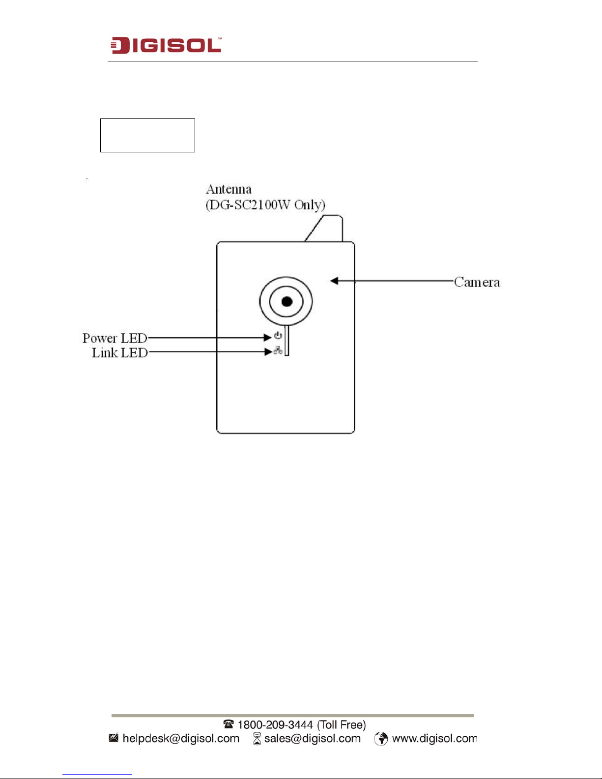
1.4 Hardware Description
Antenna: Wireless network antenna (DG-SC2100W only)
Link LED: Indicates LAN / Wi-Fi activity (Wi-Fi in DG-SC2100W only)
Power LED: Indicates system status
Camera: Video camera with lens
Front View
Page 9

DG-SC2100/DG-SC2100W User Manual
9
Tripod Connector: Connects to any standard tripod / camera wall holder.
WPS / Reset Button: Press and release this button to activate WPS mode; Keep this
button pressed for 10 seconds to clear all settings of this camera.
Power Jack: Connect to 5V power adapter.
Ethernet LAN Jack: Connect to LAN by using Ethernet cable.
R
ear View
Page 10

DG-SC2100/DG-SC2100W User Manual
10
LED Indicators description
LED Name Power Link Status Description
Booting
Flash
Flash
System Ready ON OFF
LAN connected ON ON
Data transferring ON Quick Flash
Activate WPS,
push the
WPS/Reset button
and release within
5 seconds.
ON Slow Flash The configuration should be
finished within 120 sec., after
which the Link Status LED will
go back to the original status.
Reset to default,
keep the
WPS/Reset button
pressed for more
than 10 seconds
Quick Flash ON The 2 LEDs will turn off when
reset to default takes effect and
the system will reboot.
Page 11
DG-SC2100/DG-SC2100W User Manual
11
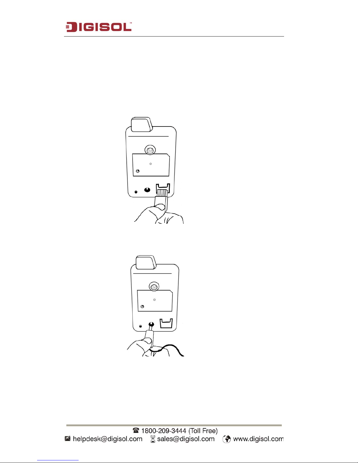
1.5 Camera Installation
Please follow the instructions mentioned below to set up your IP camera.
1. Unpack the product package and check if anything is missing.
2. Insert supplied LAN cable to 'LAN' jack. You can skip this step if wireless network
is to be used.
3. Plug the power adapter to the wall socket, and connect the power connector to the
power jack located at the rear of the IP camera.
4. Mount the IP Camera on the tripod stand and align the tripod stand such that the
camera captures the view of the area to be monitored.
Page 12
DG-SC2100/DG-SC2100W User Manual
12
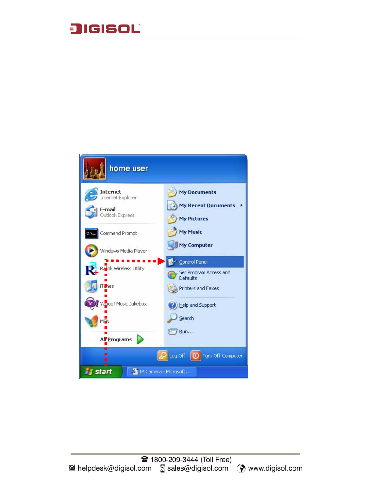
1.6 Locate the IP Address of this IP Camera
Default IP address of this IP camera is 192.168.2.3. If you wish to assign another IP
address to this IP camera, you have to log onto the web configuration interface of the
camera first.
If the left three fields of the IP address of your computer is not 192.168.2, you’ll have
to change the IP address of your computer first:
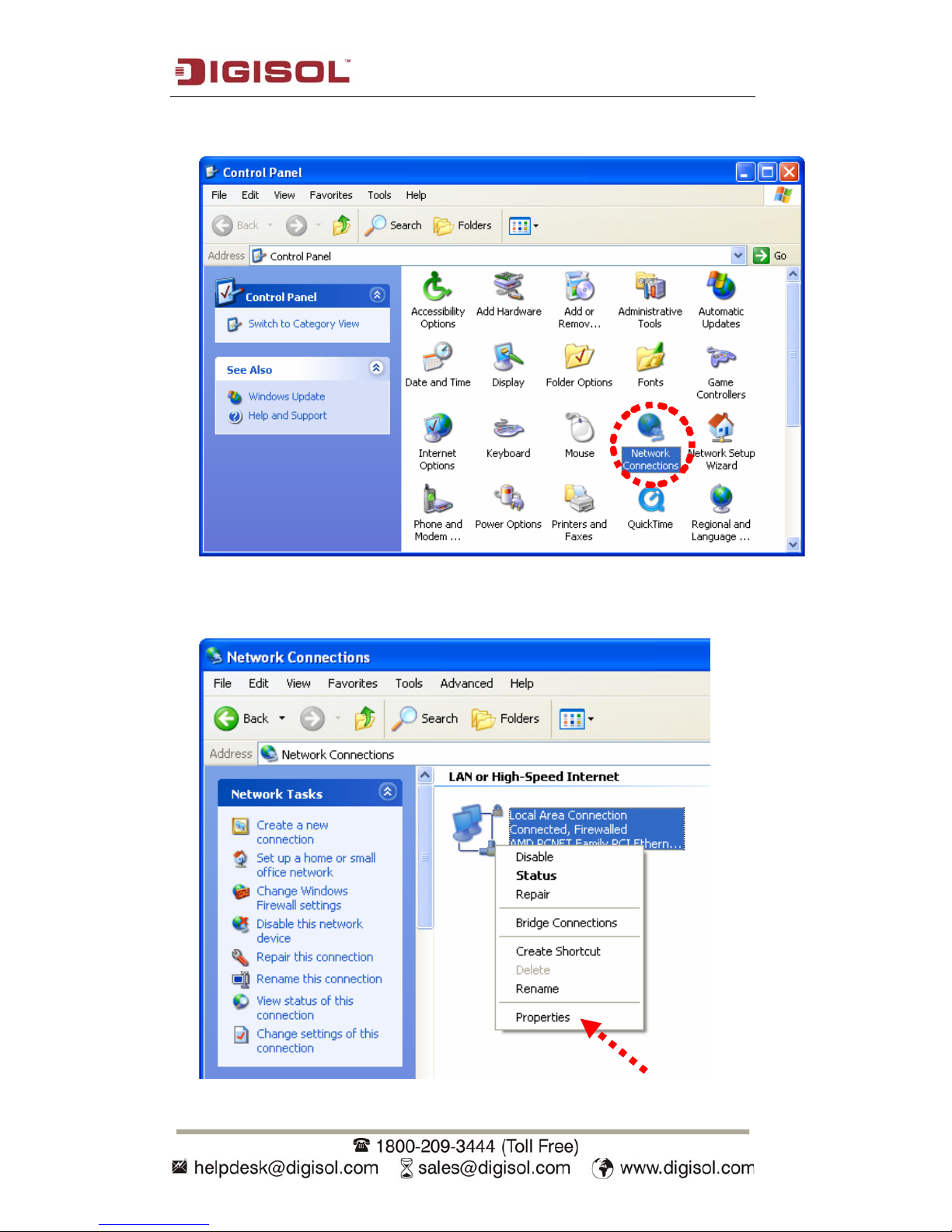
1.
Click ‘Start’ -> ‘Control Panel’
Page 13
DG-SC2100/DG-SC2100W User Manual
13
2. Double-click ‘Network Connections’ icon.
3.
Right-click ‘Local Area Connection’, and click ‘Properties’.
Page 14

DG-SC2100/DG-SC2100W User Manual
14
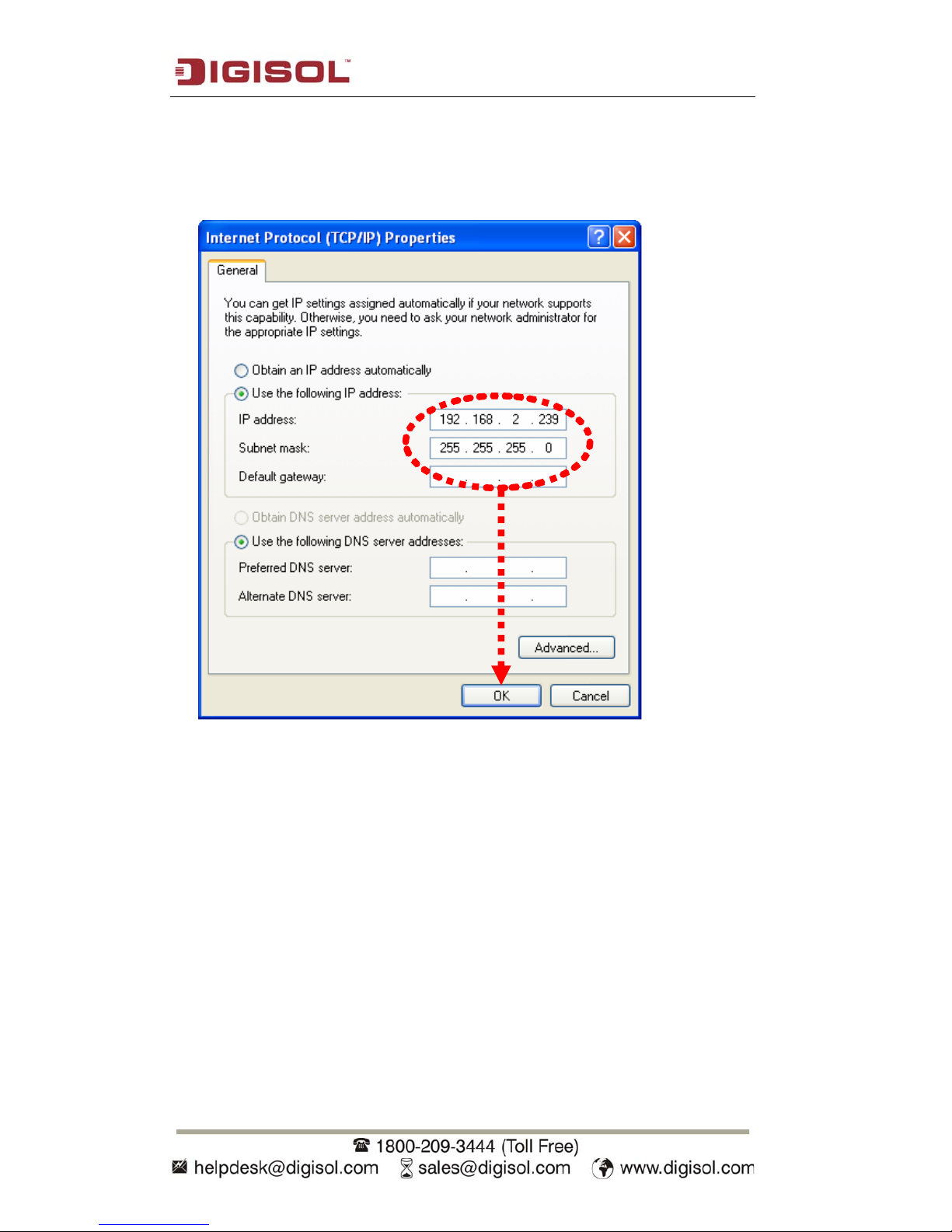
4. Select ‘Internet Protocol (TCP/IP)’, then click ‘Properties’.
Page 15
DG-SC2100/DG-SC2100W User Manual
15
5. In ‘IP address’ field, please fill in any IP address that begins with ‘192.168.2’, and
ends with a value greater than 2 and less than 254 (You can use the example in the
picture ‘192.168.2.239’). In the Subnet mask field, please fill ‘255.255.255.0’.
Please keep all other fields empty, and click ‘OK’.
If you changed the IP address of this IP camera and you cannot recollect it, there are 2
methods to recover it:
a. Press and hold the ‘Reset’ button located at the bottom of this IP camera, to
clear all settings of the IP camera and reset the IP address back to
192.168.2.3. You’ll lose all settings in the IP camera.
b. Ask the network administrator to check the DHCP release table, if the camera
was set to obtain the IP address by DHCP, a new record will be added to the
DHCP release table on the DHCP server. (when the IP camera is connected to
the local area network)
Page 16
DG-SC2100/DG-SC2100W User Manual
16
1.7 Using Camera Admin Software to Locate Camera
If you can’t connect to the camera by the instructions given in last chapter, you can
use camera admin software to search the camera which is connected to your local area
network. The admin software is also capable to locate multiple cameras on your local
area network.
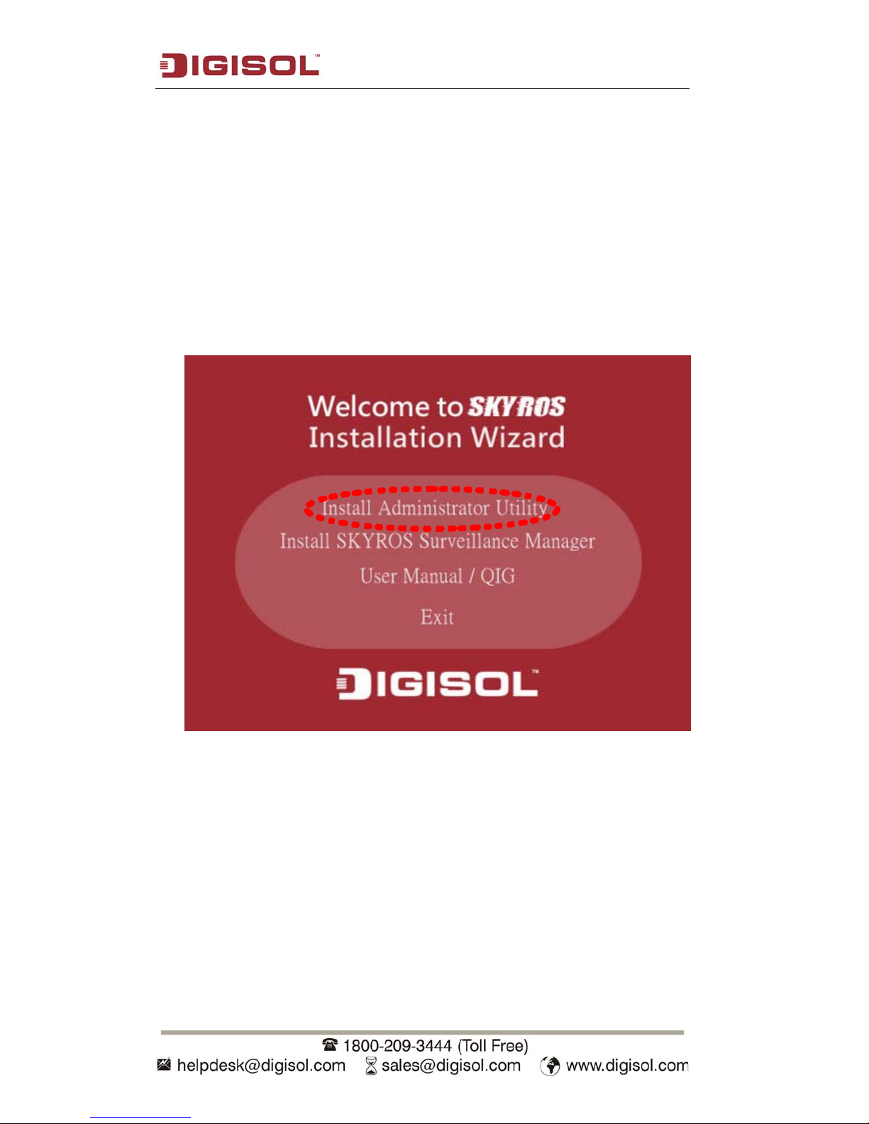
Please insert the Installation Software CD supplied in the product package, and the
CD will automatically run. Click on the ‘Install Administrator Utility’.
Page 17
DG-SC2100/DG-SC2100W User Manual
17
Then follow the below mentioned instructions to install and use camera admin
software:
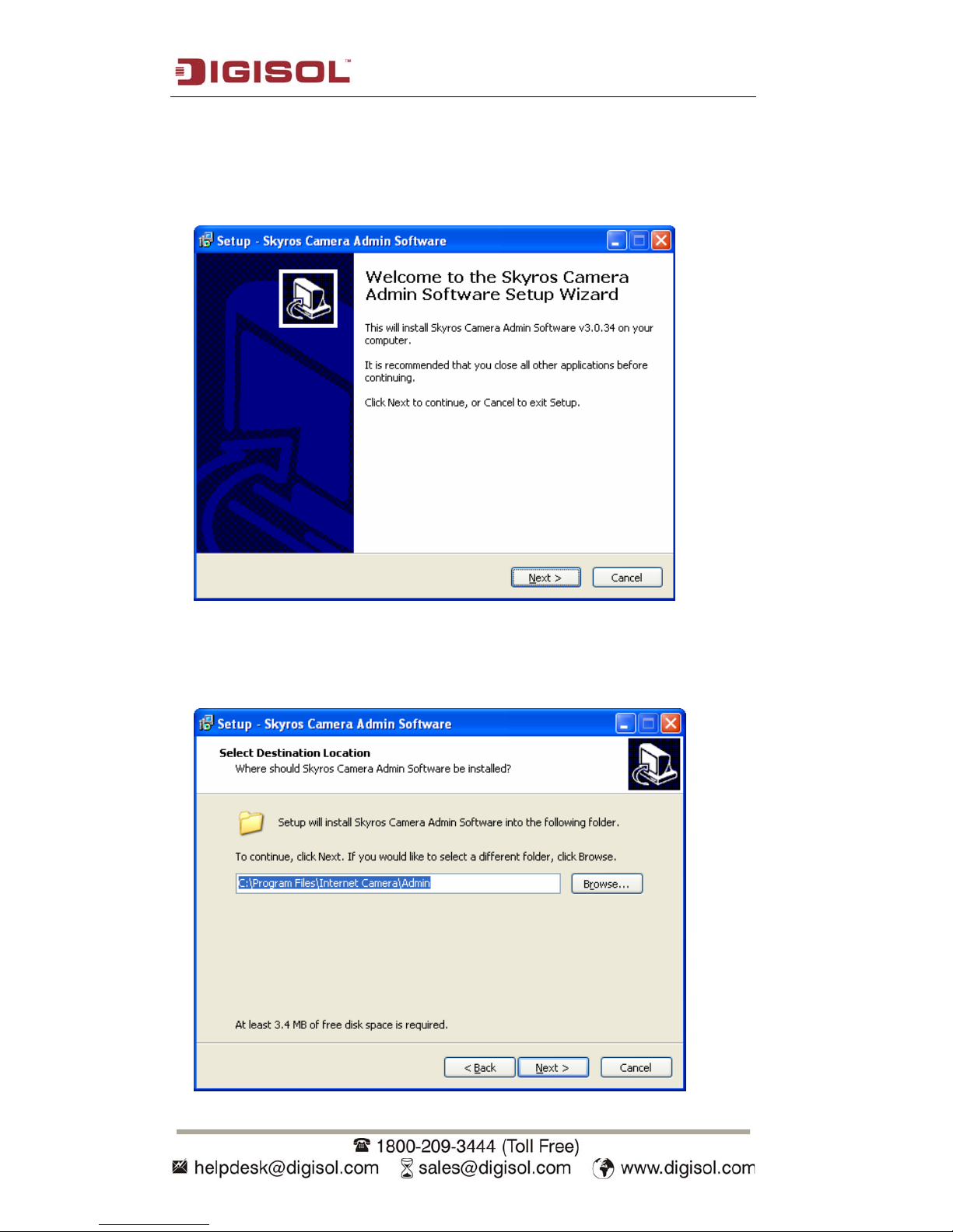
1. Click ‘Next’ to start the installation of SKYROS Camera Admin software:
2. You can change the installation folder of camera setup software here, click
‘Browse’ to select an existing folder or you can just click ‘Next’ to use
default installation folder:
Page 18

DG-SC2100/DG-SC2100W User Manual
18
3. If you wish to create desktop icon and / or quick launch icon for camera
admin software, please check corresponding box, and click ‘Next’ to
continue.
4. You’ll see a brief of all options you selected, click ‘Install’ to install camera
admin software now or click ‘back’ to go back to previous steps to change
settings.
Page 19

DG-SC2100/DG-SC2100W User Manual
19
5. When you see this message, the installation of camera admin software is
complete. If you wish to launch camera admin software now, keep ‘Launch
Skyros Camera Admin Software’ box checked, and click ‘Finish’ to close
installation utility.
Once the camera admin software is launched, all cameras found on your local area
network will be displayed:
Page 20
DG-SC2100/DG-SC2100W User Manual
20
All camera-related information will be displayed here. If you wish to connect to a
certain camera by web browser, double-click the camera listed here.
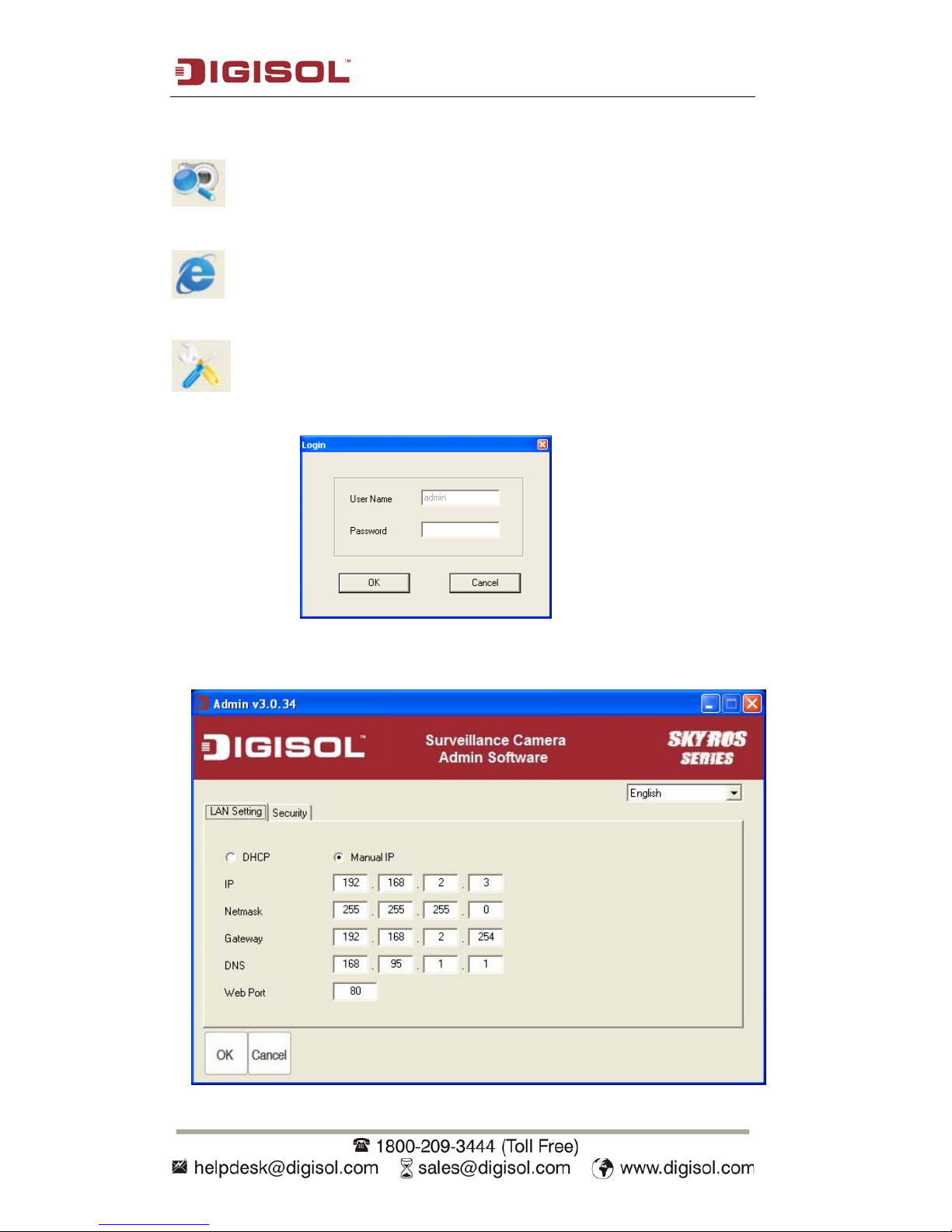
Search camera: Click this button to search all cameras on the local area
network again.
Browse camera via web: Select a camera from the displayed list, and then
click this button to connect to the camera by web browser.
Configure camera: Click this button to configure camera’s network and
security setting. You’ll be prompted to input camera’s password:
Input the password (default: 1234) and click OK to configure the camera’s network
and security settings:
Page 21
DG-SC2100/DG-SC2100W User Manual
21
In ‘LAN Setting’ page, you can configure camera’s network settings. Select ‘DHCP’
to set the camera to obtain an IP address from the DHCP server on the local area
network automatically, and select ‘Manual IP’ to input the IP address information
manually. Click ‘OK’ to save settings.
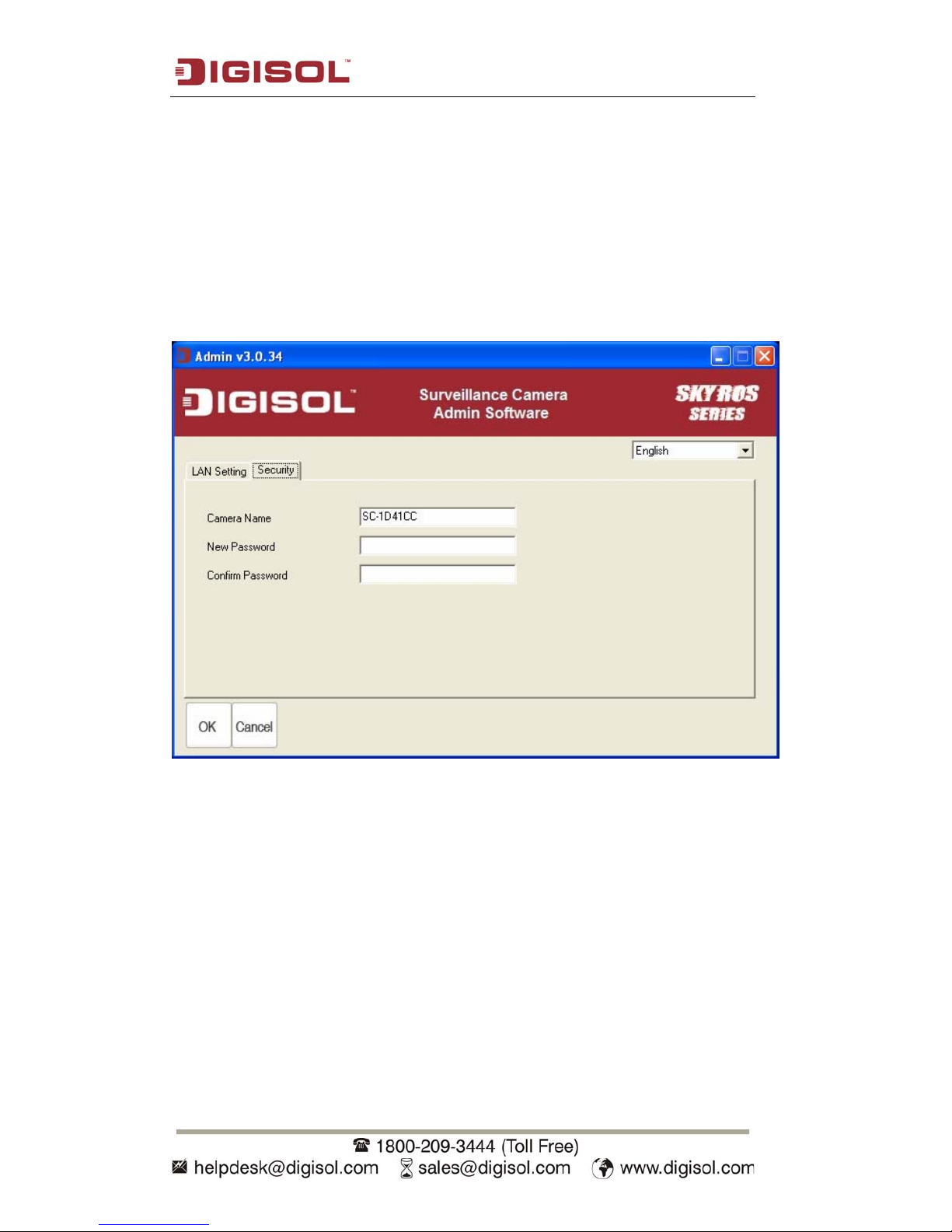
In ‘Security’ page, you can change the camera’s name and password (user name is
always ‘admin’ and cannot be changed). You have to input the same password in both
‘New Password’ and ‘Confirm Password’ fields, or you’ll be prompted to input new
password again. Click ‘OK’ to save settings or click ‘Cancel’ to discard changes.
Page 22
DG-SC2100/DG-SC2100W User Manual
22
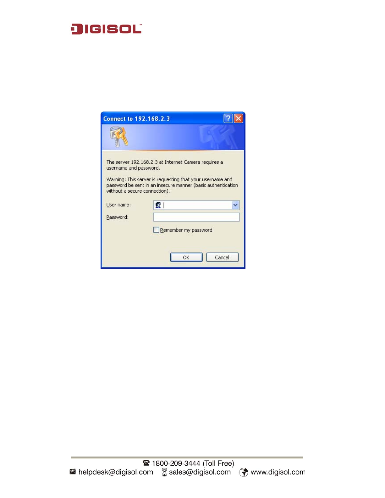
1.8 Log Onto Web Management Interface
Make sure the IP camera is correctly powered on (Power LED is on), and then launch
Internet Explorer and type the IP address of the IP camera in the address bar of
Internet Explorer. You should be prompted to input the user name and password:
Default user name is ‘admin’ and password is ‘1234’. Click ‘OK’ to continue after
user name and password has been entered.
If you’re rejected, maybe the password has been modified previously. This should not
happen if this is a newly-purchased camera. However, if the camera has been used
earlier, the password would have been changed. Please try to obtain the correct user
name / password, or else reset the camera to default settings.
Page 23
DG-SC2100/DG-SC2100W User Manual
23
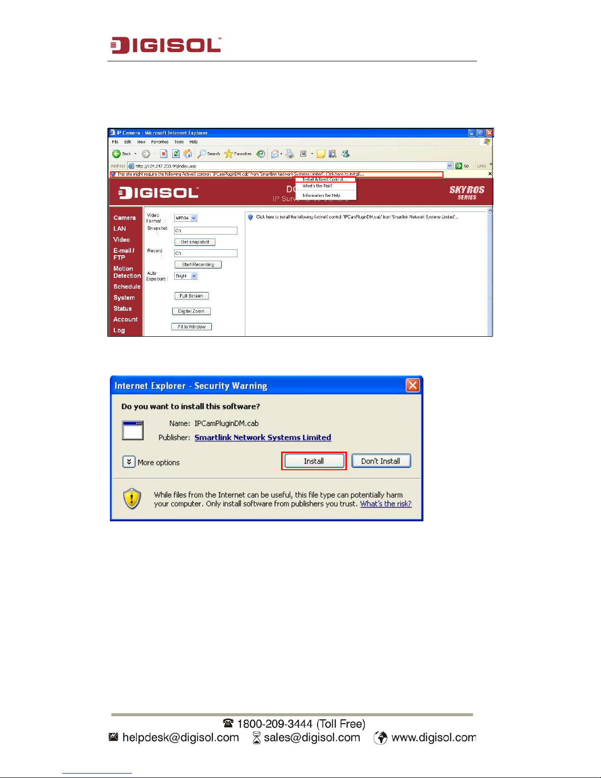
Once logged in, you may see the following messages at the top of Internet Explorer:
This IP camera requires a special ActiveX control to work. Please click on the
message, and select ‘Install ActiveX Control…’
When you’re prompted, click ‘Install’ to continue.
Page 24
DG-SC2100/DG-SC2100W User Manual
24
Now you can go back to web browser, and you should be able to see the image
captured by the camera (You may need to press F5 or CTRL-R to reload the web
page).
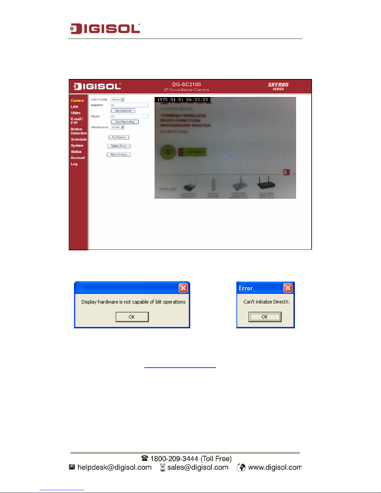
Note: If you see one of these messages (or both):
Your computer may not have the display capability that this IP camera requires, or
you don’t have Microsoft DirectX® installed. Please download Microsoft DirectX®
from Microsoft’s website (http://www.microsoft.com
), and try again.
In some cases, your computer is able to display the image from IP camera correctly,
but you’ll still see these messages. If this happens, just ignore them.
OR
Page 25
DG-SC2100/DG-SC2100W User Manual
25
2 Using Web Management Interface
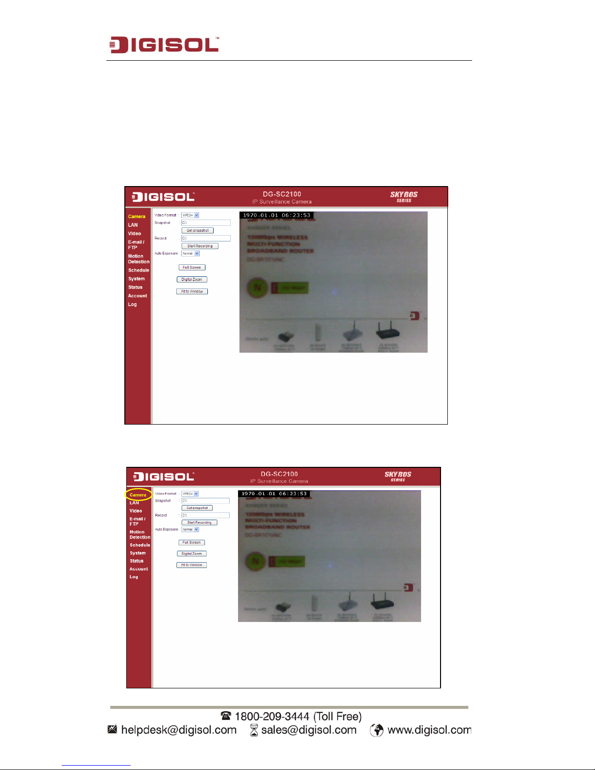
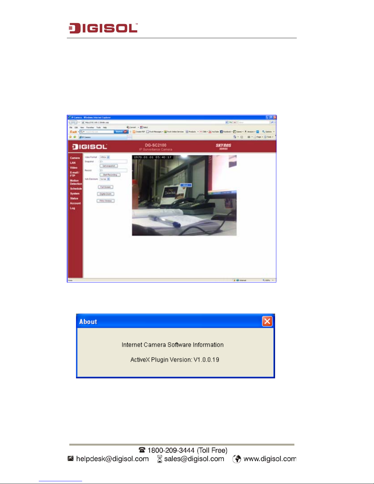
2.1 Camera Settings
The first menu when you log into web management interface is ‘Camera’, and this is
the only menu where you can see the real-time image from camera.
You can always get back to this menu by clicking ‘Camera’ on the top left of the web
management interface.
Page 26
DG-SC2100/DG-SC2100W User Manual
26
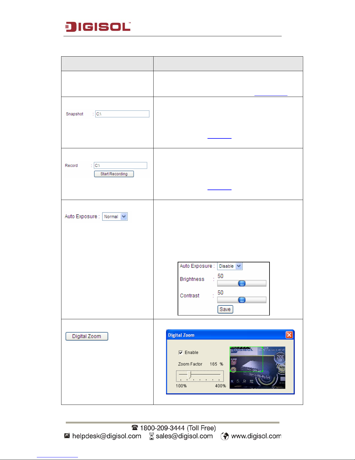
The settings in this menu are described below:
Item Description
Video Format Specifies video encoding format. You can choose
MPEG4 or MJPEG (Motion-JPEG).MPEG4 mode
also supports motion detection (refer section 2.4.2).
Snapshot Take a snapshot picture and save the picture to your
computer’s hard drive. Click on directory display and
you’ll be prompted to select a folder to save snapshot
file.
NOTE: Please see section 7 for instructions if you’re
using Windows Vista or Windows 7.
Record Start video recording and save recorded video clip to
your computer’s hard drive. Click on directory display
and you’ll be prompted to select a folder to save a
snapshot file.
NOTE: Please see section 7 for instructions if you’re
using Windows Vista or Windows 7.
Auto Exposure
Enable or disable automatic exposure control. There
are 3 levels of automatic exposure control: Dark,
Normal and Bright. Select one of them to control the
brightness of image. Select ‘Disable’ to disable
automatic exposure control. The following settings
will appear. You can manually adjust the brightness
and contrast here.
Digital Zoom
Click this button to enable digital zoom.
Page 27
DG-SC2100/DG-SC2100W User Manual
27
Check ‘Enable’ box to enable digital zoom and you
can set the percentage of zoom from 100% (no
magnification) to 400%. You can also drag the green
square by mouse and put it on the area you wish the
captured image to be magnified.
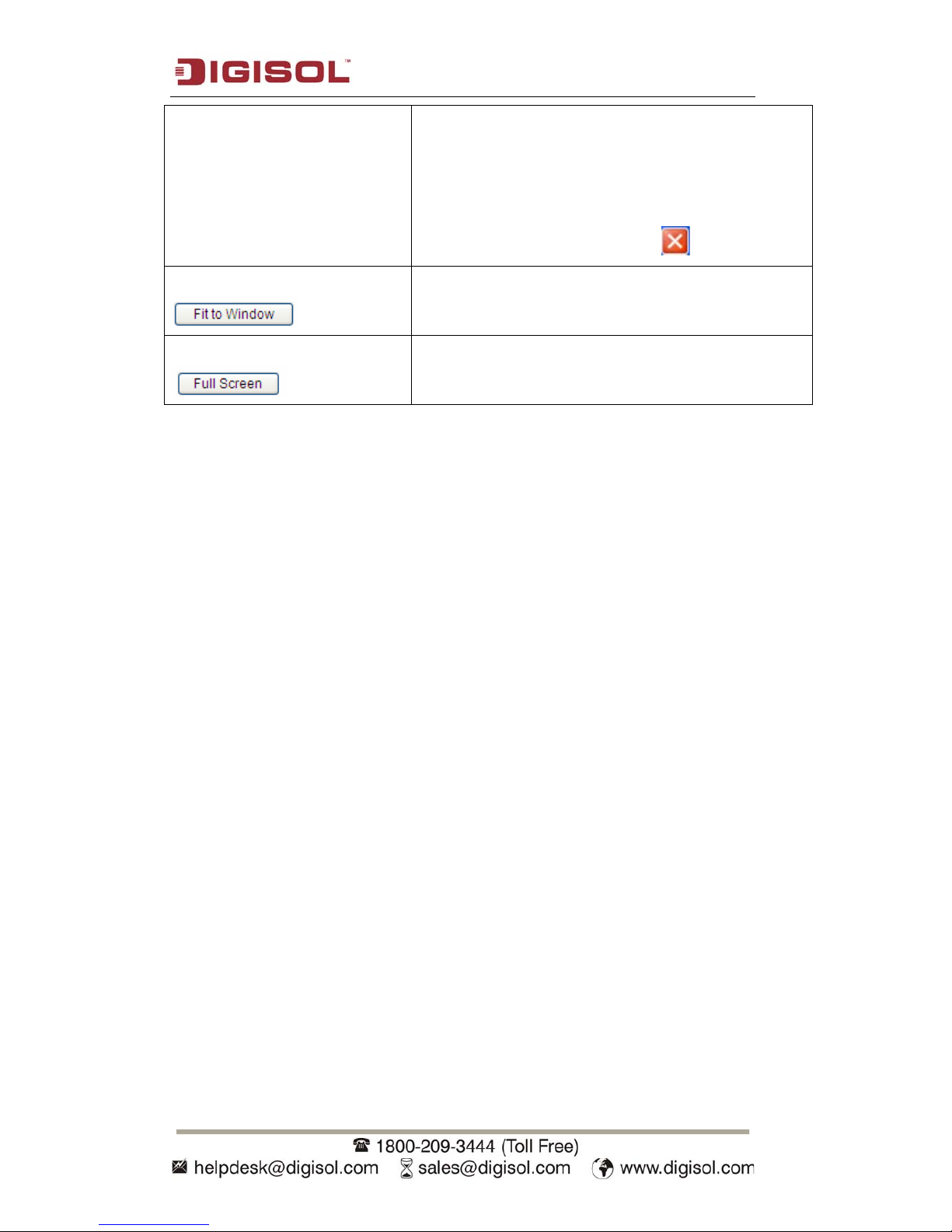
To exit digital zoom setting, press button.
Fit to Window
Click this button and captured image will fit to
window size.
Full Screen
Click this button and the image captured by the
camera will be displayed in full-screen mode. To
revert back to normal mode, double-click the image.
Note: If you’re not using Microsoft Internet Explorer as web browser, some
functionalities may not work properly.
Page 28
DG-SC2100/DG-SC2100W User Manual
28
2.1.1 About
This function will provide you with the version number of current IP camera plugin,
which is useful when you need online support.
To see version information, right-click on the image. A pop-up menu will appear:
Select ‘About’ and the version information will appear:
Page 29
DG-SC2100/DG-SC2100W User Manual
29
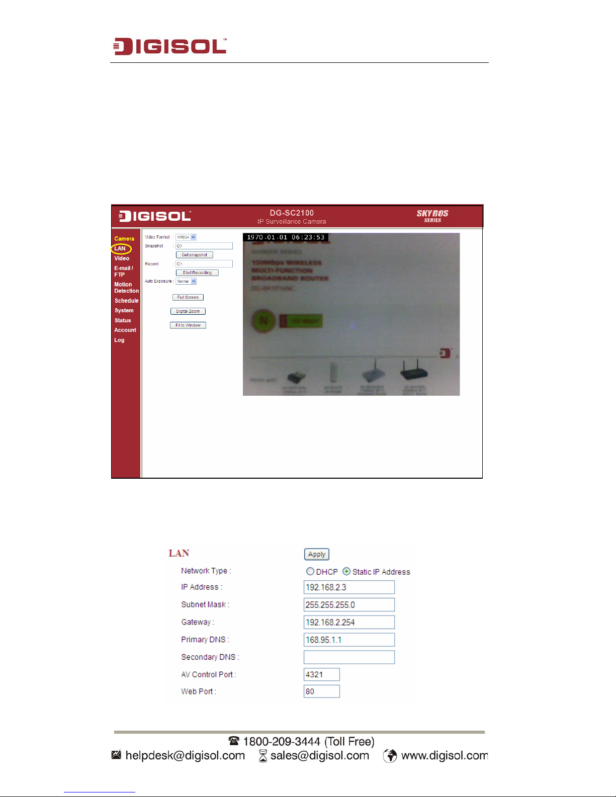
2.2 LAN
All network-related settings can be found in this menu, and you have to specify
TCP/IP parameters in this menu if you want to change IP address, Dynamic DNS and
activate UPnP function.
You can access this menu by clicking ‘LAN’ on the web management interface.
2.2.1 IP address
Y
ou can define the IP address and select the port number you wish to use here.
Page 30

DG-SC2100/DG-SC2100W User Manual
30
The description of every setting in this menu will be given below:
Item Description
Network T ype This camera can automatically obtain the IP address
from DHCP server (if available), or a fixed IP
address can be assigned to it. Select ‘DHCP’ to
obtain IP address automatically or ‘Static IP
Address’ to assign this IP camera with a fixed IP
address.
When ‘DHCP’ is selected, IP address parameters
below will be grayed out.
IP Address Specify the IP address for this IP camera here.
Subnet Mask Specify the subnet mask for this IP camera here.
Gateway Specify the gateway address of the local network
here.
Primary DNS Specify the IP address of DNS server here. Please
input IP address only. If you don’t know the address
of DNS server, ask network administrator or your
ISP for help.
Secondary DNS Specify the IP address of backup DNS server here.
When primary DNS is unreachable, IP camera will
use the IP address specified here as DNS server.
This field is optional.
AV Control Port Specify the port number used for video transfer. If
you have firewall on your network, you need to
allow computers on Internet to access the port
number of the IP address of IP camera, or you’ll not
be able to view video from Internet.
Web Port Specify the port number of web management
interface here. If it’s not 80, you’ll have to add
‘:port’ after the IP address / hostname of this IP
camera.
For example, if the HTTP port number you
specified here is 90 and the IP address of IP camera
is 10.20.20.30, then you have to input
‘http://10.20.20.30:90’ in the address bar of Internet
explorer.
Click ‘Apply’ to save settings and make the new settings take effect.
Page 31

DG-SC2100/DG-SC2100W User Manual
31
2.2.2 RTSP
RTSP (Real-Time Streaming Protocol) allows you to view live video captured by IP
camera. You can set RTSP related settings here.
The description of every setting in this menu will be given below:
Item Description
Enable RTSP Select ‘Enable’ to activate RTSP function of this IP camera, select
‘Disable’ to disable it.
RTSP Port Input the port number which RTSP will use. Default setting is 554.
RTSP Path Input the path of RTSP stream.
RTP Port Range Input the port range of RTP. Default setting is 50000 to 60000.
Click ‘Apply’ to save settings and make the new settings take effect.
Page 32

DG-SC2100/DG-SC2100W User Manual
32
2.2.3 Dynamic DNS
If your ISP does not give you a fixed Internet IP address (i.e. the Internet address
you’re using when you access the Internet is not always the same – ask your ISP for
detailed information), you can use this function to help you locate the IP address of
this IP camera when you’re away from home or office.
Before you can use this function, you’ll need to apply for an account at no-ip.com
(http://www.no-ip.com). Detailed instructions of how to apply a new account can be
found on no-ip.com’s website. (Refer section 4 to obtain a free no-ip account).
The settings in this menu are described below:
Item Description
Enable DDNS Select ‘Enable’ to activate Dynamic DNS function of this IP
camera, select ‘Disable’ to disable it.
Provider Select dynamic DNS service provider here.
Host Name Input dynamic DNS host name here.
User Name Input dynamic DNS user name here, must be the same as the
one you applied on no-ip.com.
Password Input dynamic DNS password here, must be the same as the
one you applied on no-ip.com.
Click ‘Apply’ to save settings and make the new settings take effect.
Page 33

DG-SC2100/DG-SC2100W User Manual
33
2.2.4 UPnP
When UPnP function is activated, all UPnP-compatible computers / network devices
will be able to discover this IP camera automatically (only those in the same local
network).
This function is useful and you don’t have to remember the IP address of this IP
camera. Simply open ‘My Network Places’ and the icons for the IP Cameras can be
seen.
The settings in this menu are described below:
Item Description
Enable UPnP Select ‘Enable’ to activate UPnP function of this IP camera, select
‘Disable’ to disable it.
Click ‘Apply’ to save settings and make the new settings take effect.
Once UPnP function is activated, a popup message as shown below will appear:
Click the message to open ‘My Network Places’, and you’ll see the IP camera:
Page 34

DG-SC2100/DG-SC2100W User Manual
34
You can double-click the icon to launch Internet Explorer and log onto IP camera’s
web management interface directly.
Page 35

DG-SC2100/DG-SC2100W User Manual
35
2.2.5 LoginFree
You can specify a filename here and everyone who knows this filename can gain
access to the picture captured by the IP camera with this name with .jpg file extension.
For example, if the filename you specified here is ‘loginfree’ and your IP camera’s IP
address is ‘192.168.2.3’, then everyone on the network can access the picture taken by
the IP camera at ‘http://192.168.2.3/loginfree.jpg’.
This function is for convenience only, and anyone who knows this filename will be
able to see the picture taken by your IP camera. Please think again before you use this
function.
The setting in this menu is described below:
Item Description
LoginFree Specify the file name of the picture here. If you want to disable this
function, leave it blank.
Click ‘Apply’ to save settings and make the new settings take effect.
Page 36

DG-SC2100/DG-SC2100W User Manual
36
2.3 WLAN Parameters
These are the parameters that need to be set to connect to the Wireless network.
Page 37

DG-SC2100/DG-SC2100W User Manual
37
You can access this menu by clicking ‘WLAN’ on the web management interface.
The settings in this menu are described below:
Item Description
Self Pin Code A random 8-digit code will be displayed here. If the
wireless AP you wish to connect to supports
PINCODE, please input this code to the AP you wish
to connect.
Configure via Push Button If the wireless AP you wish to connect to supports
push button WPS configuration, click ‘Start PBC’ and
press the WPS button on the wireless AP to start
pairing.
Configure via PinCode If the wireless AP already generates an 8-digit code,
please input the SSID of the AP here and click ‘Start
PIN’ button to start pairing.
Wireless Connection Select ‘Enable’ to activate wireless network function
of this IP cam era, select ‘Disable’ to disable it.
Network T ype Select the network type of the wireless connection.
Available options are ‘Infrastructure’ (Connect the IP
camera to a wireless access point) and ‘Adhoc’ (This
IP camera will become a stand-alone wireless network
point, other wireless computers / devices can discover
this IP camera and connect to it without wireless
access point).
You can set to ‘Adhoc’ when you don’t have any
wireless access point, but your computer has wireless
network card. Set to ‘Infrastructure’ when you have
Page 38

DG-SC2100/DG-SC2100W User Manual
38
wireless access point, and you have computers with
wired network connection.
Available Networks Displayed here are all the wireless access points
detected by this IP camera. Please note not all access
points will be displayed at the same time, if the access
point you wish to connect does not appear, you may
have to click ‘Refresh’ button several times until it
appears.
The description of all the fields are provided below:
Connect: You can select the wireless access point you
wish to connect here.
SSID: The SSID of all the detected wireless access
points will be shown here. Some wireless access points
may hide their SSID, in which case, you have to
identify them by their MAC address.
MAC Address: In case there are many wireless access
points in proximity or some wireless access points hide
their SSID, you can use MAC address to distinguish
them.
Signal: Shows the radio signal strength in percentage.
Channel: Shows the radio channel of the wireless
access point.
Encryption: Shows the encryption type used by the
wireless access point. You must use the same
encryption type if you wish to connect to a certain
wireless access point. If the wireless access point does
not use encryption, ‘Disabled’ will be displayed here.
Network Type: Shows the network type of a certain
wireless access point (Infrastructure or Adhoc).
SSID Input the SSID of the wireless access point you wish to
connect. It should be less than 32 alphanumerical
characters.
When you select a wireless access point above, it’s
SSID will be filled in this field automatically.
However, if the SSID is not displayed, you need to
Page 39

DG-SC2100/DG-SC2100W User Manual
39
know its SSID and input it here, or you will not be able
to connect it.
Channel Select the radio channel you wish to use here. When
network type is ‘Infrastructure’, the radio channel is
auto-selected according to the channel that wireless
access point uses. You can only select the channel
number when network type is ‘Adhoc’.
Basic Rate You can select the wireless data transfer rate here,
from 1Mbps to 54Mbps. Maximum transfer rate for
802.11b wireless network is 11Mbps and maximum
transfer rate for 802.11g wireless network is 54Mbps.
If you have a wireless router other than 802.11g
standard, select Auto under Basic rate option.
It’s recommended to select ‘Auto’, so the data transfer
rate will vary according to the actual signal strength
and quality.
Authentication Select the wireless authentication here. This setting
must be the same as that in the selected wireless access
point.
When you select a wireless access point from the list,
it’s authentication type will be selected automatically.
The same should not be modified, else the IP Camera
will not be able to connect to the wireless access point.
Available options are: None (no authentication), Open
System, Shared Key System, WPA-PSK, WPA2-PSK
and WPA None (WPA None is only for Adhoc).
Encryption T ype Select the wireless authentication here. This setting
must be the same as that in the selected wireless access
point.
When you select a wireless access point from the list,
it’s encryption type will be selected automatically. The
same should not be modified, else the IP Camera will
not be able to connect to the wireless access point.
Available options are: None, WEP, TKIP and AES. The
options available here will vary depending on the
authentication type selected. If an authentication type
does not support encryption, this field will be grayed
out.
Page 40

DG-SC2100/DG-SC2100W User Manual
40
WPA Pre-Shared Key Input the WPA pre-shared key here.
This field is only available when authentication type is
WPA-PSK or WPA2-PSK, and will be grayed out
when other authentication type is selected.
WEP Key Length Please select the key length when you use WEP
encryption. Available options are 64-bit and 128-bit.
Selecting ‘128-Bit’ is safer, however, it would make
the network a bit slower.
If the key length is 64-bit, you should input 10 HEX
characters or 5 ASCII characters, like 112233aabb
(HEX) or MYWEP (ASCII).
If the key length is 128-bit, you should input 26 HEX
characters or 13 ASCII characters, like
11223344556677889900abcdef (HEX) or
myweppassword (ASCII).
WEP Key Format Select the Key Format of WEP key here. Available
options are ‘HEX’ and ‘ASCII’.
When you select ‘HEX’ WEP key format, you can only
use numbers (0 to 9), and alphabets a to f as WEP key;
when you select ‘ASCII’ WEP key format, you can use
all alphanumerical characters, and is case sensitive.
Default Key Select the default key set that the IP camera should use
for connecting to the wireless access point when WEP
encryption is used.
Available options are 1 to 4.
WEP Key 1 Input the 1st set of WEP key here. At least one set of
WEP key is required when WEP encryption is used.
Only 1st WEP key should be used if there is only one
WEP key.
WEP Key 2 Input the 2nd set of WEP key here.
WEP Key 3 Input the 3rd set of WEP key here.
WEP Key 4 Input the 4th set of WEP key here.
Click ‘Apply’ to save settings and make the new settings take effect.
Page 41

DG-SC2100/DG-SC2100W User Manual
41
2.4 Video
You can change video-related settings of this IP camera in ‘Video’ menu. You can
access this menu by clicking ‘Video’ on the top left of the web management interface.
There are 3 types of video settings for this IP camera.
Page 42

DG-SC2100/DG-SC2100W User Manual
42
2.4.1 Dual Mode
This IP camera supports two video encoding formats: MPEG4 and MJPEG. You can
select the encoding format from one of them.
The setting in this menu is described below:
Item Description
Default V ideo
Format
Specify default video encoding format of this IP camera here.
Available options are MPEG4 and MJPEG.
Click ‘Apply’ to save settings and make the new settings take effect.
2.4.2 MPEG4
If you selected ‘MPEG4’ as the video encoding format for this IP camera, you can
specify the parameters of MPEG4 video encoder here.
The settings in this menu are described below:
Item Description
Video
Resolution
Specify video resolution of MPEG4 video encoder. Available options
are VGA, QVGA and QQVGA resolution. VGA resolution provides
more details than QVGA and QQVGA, but requires more network
bandwidth.
Page 43

DG-SC2100/DG-SC2100W User Manual
43
Video Quality Specify video quality. There are two video quality types: CBR
(Constant Bit Rate) and VBR (Variable Bit Rate):
CBR: The video bit rate is fixed, you can select a bit rate from
dropdown menu. Higher bit rate means better video quality. But if
the network bandwidth is limited, selecting a lower bit rate will help.
VBR: Video bit rate is variable based on the video content being
transferred. There are 5 levels of settings from ‘Lowest’ to ‘Highest’.
Selecting ‘Lowest’ will lower video quality and save network
bandwidth; if a better video quality is required, select ‘High’ or
‘Highest’.
Video Frame
Rate
Specify video refresh rate of MPEG4 video encoder. Higher video
refresh rate provides more details about motion, but requires more
network bandwidth.
CAUTION: Choosing a low frame rate will save bandwidth, but may
will not be able to capture every motion if the object being monitored
by the IP camera is moving fast.
Click ‘Apply’ to save settings and make the new settings take effect.
2.4.3 MJPEG
If you selected ‘MJPEG’ as the video encoding format of this IP camera, you can
specify the parameters of MPEG4 video encoder here.
The description of every setting in this menu will be given below:
Item Description
Video Resolution Specify video resolution of MJPEG video encoder. Available
options are VGA, QVGA and QQVGA resolution. VGA
resolution provides more details than QVGA and QQVGA, but
requires more network bandwidth.
Video Quality Specify video encoding quality of MJPEG video encoder. There
are five levels of video quality from highest to lowest. Higher
Page 44

DG-SC2100/DG-SC2100W User Manual
44
video quality provides better video quality, but requires more
network bandwidth.
Video Frame Rate Specify video refresh rate of MJPEG video encoder.
Higher video refresh rate provides more details about motion, but
requires more network bandwidth.
CAUTION: Choosing a low frame rate will save bandwidth, but
may not be able to capture every motion if the object being
monitored by the IP camera is moving fast.
Click ‘Apply’ to save settings and make the new settings take effect.
Page 45

DG-SC2100/DG-SC2100W User Manual
45
2.5 Email & FTP
This IP camera is capable of sending an Email or performing an FTP upload of the
captured image, when a motion is detected. This is very convenient since the IP
camera will guard the environment and automatically intimate certain events
eliminating the need of a person to continuously look at the display/monitor.
You can access this menu by clicking ‘E-Mail & FTP’ on the web management
interface.
Below are the instructions for setting up of Email and FTP.
Page 46

DG-SC2100/DG-SC2100W User Manual
46
2.5.1 Email Settings
These settings are used to send the captured picture via Email:
The settings in this menu are described below:
Item Description
Recipient
E-Mail Address
Input the recipient’s Email address here. If you have more than one
Email recipient, please add a “;“(semicolon) mark between every
Email address. All characters shouldn’t exceed 127 characters.
SMTP Server Input the IP address or host name of the SMTP server (the server that
delivers the Email).
If you don’t know, please refer to the SMTP server you’re using in
your Email software (like Outlook, Outlook Express etc.), or check
with your network administrator or ISP.
SMTP Port Input the mail server’s SMTP port here. Most of the mail servers use
port number 25.
Sender E-Mail
Address
Input the Email address of mail sender, this will help in identifying
IP camera which captured the mailed image.
NOTE: Some mail servers would reject to deliver the Email from
unknown sender. Hence it’s recommended to input an Email address
here.
SSL If SSL encryption is required to connect to the SMTP server, select
‘Enable’ or SMTP connection may fail; select ‘Disable’ if your
SMTP server doesn’t support SSL encryption. If in doubt, check with
your ISP or mail server’s administrator.
SMTP
Authentication
Some SMTP servers require mail senders to be authenticated before
they can send an Email. In such a case, please select ‘Enable’, or else
select ‘Disable’. If you don’t know, please refer to the SMTP server
Page 47

DG-SC2100/DG-SC2100W User Manual
47
you’re using in your Email software (like Outlook, Outlook Express
etc.), or check with your network administrator or ISP.
User Name Please input the user name of SMTP server here, if your SMTP
server requires the use of authentication.
Password Please input the password of SMTP server here, if your SMTP server
requires the use of authentication.
Click ‘Apply’ to save settings and make the new settings take effect.
Once configured, click ‘Send a test email’ to verify the email setting.
2.5.2 FTP Settings
These settings are used to send the captured picture by FTP:
The settings in this menu are described below:
Item Description
FTP Server Input the IP address or host name of the FTP server.
FTP Port Input the port number of the FTP server here.
User Name Input the user name of the FTP account here.
Password Input the password of the FTP account here.
Remote Folder Input the remote folder’s name provisioned in the FTP server here. If
nothing is specified here, all uploaded image files will be placed in
FTP server’s root directory.
Please check with the FTP server’s administrator for the folder name
that can be used to store the images from the IP Camera. This is
required as the folders in the FTP servers may be secured with access
(read / write) permissions.
Page 48

DG-SC2100/DG-SC2100W User Manual
48
Passive Mode Select ‘Enable’ to use passive mode to send file or select ‘Disable’ so
as to not use passive mode to send file.
Most of the FTP servers can work fine in both Passive and Non-
Passive modes. However, if in doubt, the FTP servers administrator
should be able to help.
Click ‘Apply’ to save settings and make the new settings take effect.
Once configured, click ‘Upload a test file’ to send a file to the FTP to verify the
functioning of the settings.
Page 49

DG-SC2100/DG-SC2100W User Manual
49
2.6 Motion Detection
2.6.1 Basic Settings
Motion detection function makes this IP camera act as a non-stop guard. Continuous
manual monitoring of the images from the camera is not required. The camera can
detect motions and automatically send intimations. Once motion is detected, a
captured image can be sent to you by Email or FTP.
You can access this menu by clicking ‘Motion Detection’ on the web management
interface.
Page 50

DG-SC2100/DG-SC2100W User Manual
50
Following screenshot shows the Motion Detection Settings:
The settings in this menu are described below:
Item Description
Motion Detection
Enable
Select ‘Enable’ to start motion detection, and select ‘Disable’ to
disable it.
Next Event
Detected Interval
After a motion is detected and intimations are sent via email/ftp,
no more intimation will be sent for the period mentioned here.
This is the minimum duration between any two intimations of
Motion Detection.
Please specify a time interval that suites your need. If the time
interval is too long, you may not be able to know what has
happened between time interval; if the time interval is too short,
you may receive too many unnecessary images, and consumes
too much disk storage space on Email and / or FTP server.
Send snapshot file
to Email
Select ‘Yes’ to send a picture to the Email address you specified
in ‘E-Mail & FTP’ menu when a motion is detected, and select
‘No’ to disable this function.
E-Mail Subject Set the subject of Email being sent here. This will help you to
distinguish the Email sent by this IP camera from others.
Send snapshot file
to FTP
Select ‘Yes’ to send a picture to the FTP server you specified in
‘E-Mail & FTP’ menu when a motion is detected, and select ‘No’
to disable this function.
Click ‘Apply’ to save settings and make the new settings take effect.
Page 51

DG-SC2100/DG-SC2100W User Manual
51
2.6.2 Set up Motion Detection Region
If notification is required when motion is detected only in a certain area of captured
image, this function can be used. Any motion outside the motion detection region will
be ignored, reducing the number of unwanted motion detection notifications.
This IP camera supports up to 3 motion detection regions. To setup detection region,
Please use the mouse to drag and resize motion detection regions marked as
‘Region1’, ‘Region2’ and ‘Region3’ (appear as yellow, green and red squares on
image)
Motion detection region settings can be found at the bottom of this page:
Page 52

DG-SC2100/DG-SC2100W User Manual
52
The settings in the motion detection menu are described below:
Item Description
Region1 / Region2
/ Region3
Check the box to enable / disable a certain motion detection
area.
Sensitivity Control the detection sensitivity of motion detection of
respective motion detection regions. When sensitivity is
higher, small changes in image will cause IP camera to send an
Email / FTP notification; if you received too much unwanted
notification, try to set sensitivity to a lower value.
Refresh Click this button to take and display a new picture so you can
make real-time adjustments to motion detection region.
Save Save current motion detection settings.
Click ‘Apply’ to save settings and make the new settings take effect.
Page 53

DG-SC2100/DG-SC2100W User Manual
2.7 Schedule
You can control FTP / Email image transfer by schedule. Unlike motion detection, the
only key to trigger file transfer is time.
You can access this menu by clicking ‘Schedule’ on the web management interface.
Following screenshot shows the parameters:
53
Page 54

DG-SC2100/DG-SC2100W User Manual
54
The settings in this menu are described below:
Item Description
Enable FTP Schedule Enable or disable FTP scheduling.
Time Interval Select the time interval between 2 FTP file transfers.
File Control Control the file overwriting behavior:
Upload files with filename composed of date / time: When
a file is uploaded, it will be named as the date and time
when the file is uploaded.
Overwrite file with the same filename: When a new file is
uploaded, it will replace the old one with the same file as
specified here.
Enable E-Mail
Schedule.
Enable or disable E-mail scheduling.
Time Interval Specify the time interval between 2 emails.
Click ‘Apply’ to save settings and make the new settings take effect.
Page 55

DG-SC2100/DG-SC2100W User Manual
55
2.8 System
The system menu allows you to set some system-specific parameters, like password
and time setting. You can also upgrade the firmware of this IP camera, to make new
functions available on this IP camera. You may also clear all settings or reboot the IP
camera from this menu.
You can access this menu by clicking ‘System’ on the web management interface.
Page 56

DG-SC2100/DG-SC2100W User Manual
56
2.8.1 Camera Information
Camera information allows you to set the name and administrator’s password of this
camera.
The settings in this menu are described below:
Item Description
Camera Name The name of this IP Camera can be specified here. This
can be used to identify the camera on the network when
you have more than one IP camera in the same network.
Default name begins with ‘SC-‘followed by the last 6
characters of the MAC address of this IP camera.
Password Please specify user name admin’s password here. (The one
you need when you log onto web management interface
and use ‘admin’ as user name.
Confirm Password Please input the same password again, to ensure that there
is no typographical error.
Click ‘Apply’ to save settings and make the new settings take effect.
Page 57

DG-SC2100/DG-SC2100W User Manual
57
2.8.2 Date / Time Setting
This setting allows you to change the date and time of the clock in the IP camera. You
can set the time manually, or use network time protocol (NTP) to set the time
automatically.
The settings in this menu are described below:
Item Description
Set Date/Time
manually
Please input the date and time you wish to set here.
Date / time format is YYYY / MM / DD HH:MM:SS
Time is in 24-hour format.
You can click ‘Synchronize to PC time’ to use the time of the
computer you’re using.
Example: 24th August 2007 = 2007/ 08 / 24, and
PM 9:24:30 = 21:24:30
Time Zone Please select the time zone of the country / city from the
dropdown menu.
NTP Server Please input the IP address or host name of NTP server here.
You can use default value ‘pool.ntp.org’, or ask your ISP for the
IP address or host name, if they have one.
Enable Daylight
Saving Time
Select ‘Yes’ if your area of residence uses daylight saving; if
not, select ‘No’.
Synchronize to PC
time
Click this button and the IP camera will use the current time
setting of your computer as IP camera’s time setting.
Click ‘Apply’ to save settings and make the new settings take effect.
Page 58

DG-SC2100/DG-SC2100W User Manual
58
2.8.3 Utilities
This menu allows you to upgrade firmware, clear all settings, reboot the IP camera
and switch LED lights on/off.
The settings in this menu are described below:
Item Description
Upgrade Firmware Click ‘Browse’ button to select the firmware file that needs to be
uploaded. Then click ‘Upgrade’ button to start firmware upgrade
procedure.
It’s recommended to use wired Ethernet connection when you
use this function, and DO NOT DISCONNECT OR CLOSE WEB
BROWSER DURING UPGRADE!
Reset T o Factory
Defaults
Clear all settings in the camera. Please think again before you do
this, and then click this button to reset all settings.
NOTE: IP address will be reset to default value ‘192.168.2.3’
also. You will need to change the IP address setting of your
computer if the IP address of your computer does not begin with
‘192.168.2’, and subnet mask is not ‘255.255.255.0’, else you
will not be able to connect to this IP camera again.
Reboot Device If you find the IP camera is responding slowly or behaves
strange, you can click this button to try to reboot the IP camera,
this may help.
LED Setting Switch the LED light of this IP camera off, so ‘LAN’ and
‘WLAN’ LED on the IP camera will stop working, in case you
don’t want other people to know that the camera is transferring
data.
You can click this button again to switch LED lights on again.
Page 59

DG-SC2100/DG-SC2100W User Manual
59
2.9 Status
This menu provides all information about this IP camera, like firmware version,
device time, system time and network information.
You can access this menu by clicking ‘Status’ on the web management interface.
Following screenshot shows the parameters:
Page 60

DG-SC2100/DG-SC2100W User Manual
60
2.10 Account
If you wish to allow other people to view the image captured by this camera, but don’t
want to allow them to modify system settings, you can give them user-level user name
and password, so they can only view the images and cannot change any system
settings. When they click menus other than ‘Camera’, they will see the following
message informing that they don’t have permission to do that:
You can access this menu by clicking ‘Account’ on the web management interface.
Page 61

DG-SC2100/DG-SC2100W User Manual
61
This IP camera supports up to 16 user accounts.
The settings in this menu are described below:
Item Description
Login Specify the user name here. Please use alphanumerical
characters (0 to 9, A to Z and a to z). Not using symbols and
space.
Password Specify the password for this user here.
Confirm Password Specify the password for this user here again.
Authority Select ‘Operator’ and this user will be able to change the
settings of IP camera; select ‘Guest’ and this user can only
view the image.
Add Click ‘Add’ to add a new user with the information listed
above.
Modify To modify the information of an existing user, select his / her
user account, change the information and then click this button
to save changes.
Remove Select an existing user and click this button to remove it.
Page 62

DG-SC2100/DG-SC2100W User Manual
62
2.11 Log
All activities of this IP camera will be saved. Click on ‘Log’ menu to view these logs.
You can access this menu by clicking ‘Log’ on the bottom left of the web
management interface.
Click Refresh to get latest update.
Page 63

DG-SC2100/DG-SC2100W User Manual
63
3 Using SKYROS Surveillance Manager Software
3.1 Installing SKYROS Surveillance Manager Software
The SKYROS Surveillance Manager software provides various functions like video
recording. Please follow the below mentioned instructions to install the surveillance
software.
1. Please insert the Installation Software CD-ROM supplied in the product
package, and the CD will automatically run. Click on the Install
SKYROS Surveillance Manager.
Page 64

DG-SC2100/DG-SC2100W User Manual
64
Then follow the below mentioned instructions to install SKYROS Surveillance
Manager.
1. The following window appears, click ‘Next’.
2.
You can specify the destination folder of software installation; you can just
use the default folder, and click ‘Next’ to continue.
Page 65

DG-SC2100/DG-SC2100W User Manual
65
3. If you need the installation program to create a desktop icon or a quick launch icon,
you can accordingly select them here, and click ‘Next’ to continue.
4.
The next screen lists all options you chose in previous steps, if everything is
as configured, click ‘Install’ to start the installation procedure, or click ‘Back’
to go back to previous step to modify installation settings.
Page 66

DG-SC2100/DG-SC2100W User Manual
66
5. The installation procedure will take some time, please be patient.
6.
When you see this window, it means the software installation procedure is
complete. Please click ‘Finish’ to finish the procedure (the SKYROS surveillance
Manager Software will start once the ‘Finish’ button is clicked. However, to start
the software later, uncheck ‘Launch the SKYROS Surveillance Manager’ tick box).
Page 67

DG-SC2100/DG-SC2100W User Manual
67
3.2 Using SKYROS Surveillance Manager software
You can click ‘SKYROS Surveillance Manager ’ icon from desktop, quick launch bar,
or start menu to start the IP camera surveillance software.
Here are descriptions of all components of the SKYROS Surveillance Manager
software:
Before you start:
The SKYROS Surveillance Manager software will only work when your
monitor’s resolution is ‘1024 x 768’. Please change the resolution before
you use IP camera surveillance software, or it won’t start.
Language
Display
layout
Full screen /
Scan
PTZ Control /
Home
Recording / Configure
Cameras/General Options /
Playback / Snap shot
Close window (stop surveillance) /
Minimize window
Video display area
Message display
box
Page 68

DG-SC2100/DG-SC2100W User Manual
68
Moving the mouse cursor over certain sections of the screen provides the names of the
buttons
Below are the detailed descriptions of all buttons:
Item Description
Video displaying
area
The image of all connected cameras will be displayed here.
Language Select a language from this dropdown menu to change display
language.
Display layout
Change camera image display layout (Click a layout icon to
change camera display layout). There are 8 kinds of available
display layouts.
Full screen
Click this button to switch to full screen mode (only display
all camera’s image), press ‘ESC’ key to quit full screen mode.
Scan
Click this button and the IP camera surveillance software will
switch displaying the image of all connected camera
automatically. Click this button once to activate scan function
(scan icon will become blue ), click again to stop scanning
(scan icon will become white ).
PTZ control
There are 8 directions in PTZ control ring. If the camera you
connect supports PTZ, you can use PTZ control ring to change
the direction that camera points to.
This function is only available for supported cameras.
Home
Click this button to return the camera to ‘Home’ (default)
position.
This function is only available for supported cameras.
Recording
Start video recording.
Setup
Software / camera configuration.
Playback
Playback a recorded video file.
Page 69

DG-SC2100/DG-SC2100W User Manual
69
Snapshot
Take a snapshot of current camera.
Message display Displays all system messages like camera is disconnected etc.
Close window (stop
surveillance)
Terminates IP camera surveillance software.
Minimize window Minimizes IP camera surveillance software window.
Video display area Displays the image of all cameras by the display layout you
selected.
Page 70

DG-SC2100/DG-SC2100W User Manual
70
3.3 Configuring the SKYROS Surveillance Manager software
3.3.1 Configuring cameras
Before you use the SKYROS Surveillance Manager software, you must configure the
camera(s) you wish to connect. Please click ‘Setup’ button and the below
popup menu will appear:
Please select ‘Configure Cameras’ to configure cameras:
Note: If you’re prompted by a windows security alert which asks you if
you want to block ‘IPCamViewer’ program, please click ‘Unblock’
button, else the SKYROS Surveillance Manager software will not be
able to function correctly.
Page 71

DG-SC2100/DG-SC2100W User Manual
71
3.3.1.1 ‘Camera’ tab
In this tab you can configure all cameras you wish to connect. Up to 16 cameras can
be connected simultaneously:
Below are the detailed descriptions of all the settings:
Item Description
Channel Select the channel number you wish to set.
Camera Search All cameras found on your local network will be displayed in
the ‘Camera Search’ box.
Select Select a camera listed in the ‘Camera Search’ box, and click
‘Select’ button to automatically fill all parameters of selected
camera in the configuration fields.
Refresh Rescan all cameras on your local network. If you didn’t see
the camera you expected in ‘Camera Search’ box, or new
cameras have been introduced to your local network after last
scan.
Name* Input the name of the camera here. Default value is the last 6
bytes of camera’s MAC address; you can change the name of
camera as per your convenience.
Model Displays the model of selected camera, this field can not be
changed.
IP Address* Input the IP address of camera.
Page 72

DG-SC2100/DG-SC2100W User Manual
72
Username* Input the user name of camera.
Web Port* Input the web port of the camera. By default it’s ‘80’.
Password Input the password of camera. Default value is ‘1234’. You
should change the password if you have changed the password
of selected camera.
Video Format** Select the video encoding format of this camera (MJPEG,
H.264 or MPEG4).
Reset Clear all fields in ‘Camera Configuration’ section.
OK Save settings in this tab.
Cancel Discard all settings in this tab.
*: It is recommended to use ‘Select’ button to fill the content of this field.
**: Only available for cameras that support this function.
After you’ve configured all channels you wish to set, click ‘OK’ to save the settings,
and if everything’s correct, you’ll see the camera’s image in IP camera surveillance
software’s main menu:
Page 73

DG-SC2100/DG-SC2100W User Manual
73
3.3.1.2 Schedule Recording
In this tab, schedules for recording video captured by the IP Cameras can be predefined.
The descriptions of the settings are mentioned below:
Item Description
Channel Select the channel number for which you wish to schedule the
recording.
One Time
Schedules
You can specify the one-time schedule for selected camera;
this schedule will be executed once only.
New
(One Time
Schedules)
Click this button and a new window will appear:
Please specify the time duration of this one-time schedule (the
date and time of ‘From’ and ‘To’), then click ‘OK’ to save
settings.
Page 74

DG-SC2100/DG-SC2100W User Manual
74
Please note you must set a schedule that will happen in the
future, you cannot set a schedule in the past.
Edit You can modify a scheduled recording item. Select a schedule
in ‘One Time Schedules’ list, and click ‘Edit’ button to edit the
start and end time of this schedule.
Delete Delete a selected schedule item.
New
(Weekly
Schedules)
Click this button and a new window will appear:
You can define recording schedule that will be executed at the
specified time of certain day(s) in a week. Please check all
weekdays that apply, and set the start time in ‘From’ field. You
can set the duration of video recording in ‘Period’ field
(format is HH:MM:SS), and the end time will be calculated
automatically and displayed in ‘To’ field. You can also click
‘All Time Record’ button to define a recording schedule that
will be executed every weekday, from 12:00:00AM to
11:59:59PM.
Click ‘OK’ to save changes.
Edit You can modify a scheduled recording item. Select a schedule
in ‘Weekly Schedules’ list and click ‘Edit’ button to edit the
start and end time of this schedule.
Delete Delete a selected schedule item.
OK Save settings in this tab.
Cancel Discard all settings in this tab.
Page 75

DG-SC2100/DG-SC2100W User Manual
75
3.3.1.3 Audio
For cameras that support audio, you can use this tab to decide if you wish to hear the
audio captured by selected camera.
The settings are described below:
Item Description
Channel Select the channel number you wish to set.
Mute Audio Check this box and the IP camera surveillance software will
not play the audio captured by this camera.
Record Video Only Check this box and the IP camera surveillance software will
not record the audio captured by this camera.
OK Save settings in this tab.
Cancel Discard all settings in this tab.
Page 76

DG-SC2100/DG-SC2100W User Manual
76
3.3.1.4 Motion Recording
When this function is activated, only motions captured by the camera will be
recorded, so hard disk storage space is not wasted on images that do not need
attention.
The settings are described below:
Item Description
Channel Select the channel number you wish to set.
Enable Enable motion record function.
Disable Disable motion record function.
Recording Time Select the time duration that camera will record when a motion
has been detected from dropdown menu in seconds.
Invoke alarm when
motion is triggered
Send an alarm when a motion has been detected by the
camera.
Send mail when
motion is triggered
Send an email to a pre-defined address when a motion has
been detected by the camera.
WARNING: For applications that require high security, it is not
recommended to use this function since certain minor
changes/movements may not trigger the camera to record. This may
not be desirable.
Page 77

DG-SC2100/DG-SC2100W User Manual
77
OK Save settings in this tab.
Cancel Discard all changes done in this tab.
3.3.2 General Settings
You can set system-wide settings of this IP camera surveillance software in this menu.
3.3.2.1 ‘General’ tab
All general settings like file storage directory and recording spaces can be set here.
Page 78

DG-SC2100/DG-SC2100W User Manual
78
The settings are described below:
Item Description
Data Directory Set the directory (folder) you wish to store the recorded video
and captured image. You can click ‘Browse’ button to select a
directory in your hard disk.
Free Recording
Space
Displays remaining storage space.
Max V ideo File
Size
Defines the maximum file size of each video file. When the
size of the file exceeds this value, IP camera surveillance
software will open another file to record the video.
Scan Time Define the time period to pause between every camera switch
when you activate ‘Scan’ function.
Cycle Recording You can decide the behavior when hard disk space is full:
Disable: Do not overwrite recorded video files.
Enable: Overwrite recorded video files.
OK Save settings in this tab.
Cancel Discard all changes done in this tab.
Page 79

DG-SC2100/DG-SC2100W User Manual
79
3.3.2.2 ‘E-Mail Setting’ tab
If you want to use motion detection function and wish to get an email that contains the
image captured by the camera, please setup your email related parameters here.
The settings are described here:
Item Description
E-Mail Subject Specify the subject of sending email.
Recipient E-Mail
Address
This is the list of all email addresses you set.
New Click this button and you’ll be prompted to input the email
address. Click ‘OK’ to save changes.
Page 80

DG-SC2100/DG-SC2100W User Manual
80
Edit Select an email address from ‘Recipient E-Mail Address’ box,
and click ‘Edit’ to edit the email address.
Delete Delete selected email address.
Sender E-Mail
Address
Specify the email address of email sender.
SMTP Server Specify the IP address or host name of the SMTP server you
wish to use. For most of ISPs they will only allow its
subscriber to use their SMTP server, if you don’t know which
SMTP server you should use, please refer to the setting of your
email software or ask your ISP / network administrator.
SMTP port Specify the port number of the SMTP server you wish to use
here. By default (and the setting of most of SMTP servers) it is
‘25’.
SMTP Auth Select ‘Enable’ if your SMTP server requires authentication,
select ‘Disable’ if it’s not required. If you don’t know if your
SMTP server requires authentication, please refer to the setting
of your email software or ask your ISP / network
administrator.
SMTP Account Input the SMTP account (username) of your SMTP server
here. In most cases, it’s the same as your POP3 username (the
one you use to receive email). Please refer to the setting of
your email software or ask your ISP / network administrator if
you’re not sure about this.
SMTP Password Input the SMTP password of your SMTP server here. In most
cases, it’s the same with your POP3 password (the one you
used to receive email). Please refer to the setting of your email
software or ask your ISP / network administrator if you’re not
sure about this.
SMTP SSL/TLS If your email server requires SSL encryption, select SSL or
TLS options available in the list.
OK Save settings in this tab.
Cancel Discard all changes done in this tab.
Page 81

DG-SC2100/DG-SC2100W User Manual
81
3.3.2.3 Security
If you don’t want other people to access the SKYROS Surveillance Manager
software, you can set a password to protect it.
You’ll need to input the password every time you wish to use the SKYROS
Surveillance Manager software:
To set password, please use ‘Security’ tab in ‘General Options’ menu:
The settings are described below:
Item Description
Enable Requires password authentication when this software starts.
Disable Password authentication is not required when this software
starts.
Password Input the password you wish to use here.
Confirm Password Input the password you wish to use here again.
Page 82

DG-SC2100/DG-SC2100W User Manual
82
3.3.2.4 About
This tab shows the version number of the IP camera surveillance software you’re
using.
Page 83

DG-SC2100/DG-SC2100W User Manual
83
3.4 Change Display Layout
This IP camera surveillance software provides 8 kinds of display layout:
Each layout displays different number of cameras and camera arrangement, you can
click the icon that presents a specific kind of layout, and the video display area will
change accordingly.
Layout style 1: 1
Camera only
Displays the video of 1 camera only.
Layout style 2: 4
Cameras
Displays the video of up to 4 cameras.
Page 84

DG-SC2100/DG-SC2100W User Manual
84
Layout style 3: 6
Cameras
Displays the video of up to 6 cameras.
Layout style 4: 8
Cameras
Displays the video of up to 8 cameras.
Layout style 5: 9
Cameras
Displays the video of up to 9 cameras.
Layout style 6: 10
Cameras
Displays the video of up to 10 cameras.
Page 85

DG-SC2100/DG-SC2100W User Manual
85
Layout style 7: 13
Cameras
Displays the video of up to 13 cameras.
Layout style 8: 16
Cameras
Displays the video of up to 16 cameras.
Page 86

DG-SC2100/DG-SC2100W User Manual
86
3.5 Full-screen mode
If you want to use all available spaces on your monitor to display surveillance image,
you can click ‘Full Screen’ button to switch to full-screen mode.
To exit full-screen mode, press ‘ESC’ key.
Page 87

DG-SC2100/DG-SC2100W User Manual
87
3.6 Scan
If you have more than one camera configured, and you wish to switch the displaying
image between cameras, you can click ‘Scan’ button to switch between all configured
cameras.
Click ‘Scan’ button once to activate scan function (scan icon will become blue ),
click again to stop scanning (scan icon will become white ).
NOTE: If a camera is configured but disconnected, it will still be
displayed in a scan sequence (you’ll see nothing and you’ll see
‘Disconnected’ text displayed at the upper-left corner of display image).
Page 88

DG-SC2100/DG-SC2100W User Manual
88
3.7 PTZ
For cameras that support pan - tilt function, you can change the position that camera
points to, to see different places that fall in the scope of camera’s view.
Please select a camera in video displaying area by clicking on its image, and then
click the directions you wish the camera to move to (total 8 directions available).
Click ‘Home’ button ( ) to return to camera’s home (default) position.
Page 89

DG-SC2100/DG-SC2100W User Manual
89
3.8 Snapshot
You can take a snapshot of selected camera and save it to ‘Snapshot’ sub-folder of
pre-defined data directory.
Click snapshot button once to take a snapshot; you can take as much snapshot as you
want before hard disk is full.
3.9 Recording
You can start video recording of selected camera manually by clicking ‘Start
Recording’ button:
When recording starts, you’ll see a message displayed in message displaying box like
‘1/1 10:00:00, Camera 1 Start Manual’, which means camera 1 starts recording
manually on 1/1 at 10:00:00.
To stop recording, click ‘Start Recording’ button again, and you’ll see a message
displayed in message displaying box like ‘1/1 10:00:00, Camera 1 Stop Manual’.
Page 90

DG-SC2100/DG-SC2100W User Manual
90
3.10 Video Playback
You can playback all recorded video by clicking this button.
A new window will appear:
You have to search the video file before you can play it. There are two kinds of video
search: Time Search (search all video files that fall in a specific period of time) and
Motion Search (search all videos recorded by motion detection function that fall in a
specific period of time).
Please define the start and end date / time of the time period you wish to search, and
then click ‘Search’ button (of ‘Time Search’ / ‘Motion Search’). All found videos
will be displayed, select the video you wish to play and click ‘Play’ button to
playback.
Page 91

DG-SC2100/DG-SC2100W User Manual
91
4. Obtaining a free No-IP account
If your ISP provides dynamic (non-static) IP address to you and you cannot connect to
your IP camera when you’re away from it, here are a few simple steps to follow to get
yourself setup and online with No-IP.com's free dynamic DNS service, so you can run
your servers at your home or business without a static IP address.
1.
Launch your web browser and navigate to http://www.no-ip.com
2.
Click the "Sign-in!" link (located at the top of the page of no-ip.com’s webpage)
3.
Click ‘Sign up for an Account’ in pop-up menu.
Page 92

DG-SC2100/DG-SC2100W User Manual
92
4. You should now be logged into the No-IP.com members section. Here you can
create a hostname that you will use to connect to your server.
A hostname is used instead of your IP address whenever you want to connect to a
service at your location. Hostnames take the form of hostname.domain.com so
they're the same as names used in URLs to surf the web etc.
In order to add a host to your account, select the "Add Host" link from the
"Hosts/Redirects" menu. This will bring up the Add a Host page.
5. Now you' re ready to fill in the details of your new hostname. Here are the steps to
deal with the items on this screen:
Fill in the Hostname: box with a name of your choosing. It can be anything you like.
If you choose a name that's already in use, an error will be generated and you can then
try a different hostname.
Page 93

DG-SC2100/DG-SC2100W User Manual
93
• No-IP Free users are only able to create hostnames on one domain. If you want more
domain choices, consider upgrading to No-IP Enhanced which offers 80+ domains.
• Choose the Host Type. The default choice, DNS Host A, is usually the correct one.
Do not choose any of the other host types unless you're trying to solve a particular
problem that a DNS A record won't accommodate. If your ISP blocks Port 80 for
example, and you're trying to run a web server or other service on port 80, then you
can choose Port 80 Redirect (at that point you'll be asked to specify the port to use for
the redirection). If you're not running a web server, then do not choose this option as it
will likely prevent you from connecting properly.
• In the field marked IP Address: you should already see your current IP address. If
you wish to set the IP address of the host to be somewhere other than your current
location, you can enter that address now.
• The next two options aren't used for a basic account setup so we won't concern
ourselves with those in this article.
• When you have filled in the information for your new hostname, simply click the
"Create Host" button at the bottom of the page to save it.
Page 94

DG-SC2100/DG-SC2100W User Manual
94
5. IP Camera behind a router/firewall – Sample Configuration
If this IPCAM is not directly connected to Internet (behind router or firewall), you’ll
need to setup your router / firewall so you can access this IPCAM from other
computers on Internet.
The following instructions describe how to configure your router or firewall device so
that IPCAM can work with them. These instructions are based on a commonlyavailable residential router and these setup techniques should be easy to apply on any
other similar devices as well.
5.1 Setup Dyndns Dynamic IP address Mapping
1.
Go to your router’s setup page, and locate ‘DDNS’, ‘Dynamic DNS’, or similar
setup items.
2. Refer to last chapter (Sec 4) and obtain a Dyndns account, password, and domain
name.
Page 95

DG-SC2100/DG-SC2100W User Manual
95
3. Enable Dynamic DNS function, select ‘DynDNS’ as service provider, and fill the
information you obtained from Dyndns.org into Domain name, Account and
Password field (these field names may differ on your router).
5.2 Open Ports Required by IP CAM
1. To access IP CAM located behind router or firewall, you must open ports on
router or firewall so you can access IP CAM from Internet.
2. Go to your router’s setup page, and locate ‘NAT’, ‘Firewall’, ‘Port Mapping’,
‘Port Forwarding’, or similar setup items.
3. Enable this function, and fill IP CAM’s IP address in ‘Private IP’ (or similar field),
select ‘TCP’ or ‘BOTH’ as data type, and input these port numbers given below
for the services you wish to access from Internet in the port range field.
IP CAM web configuration and view live image: 80
RTSP: 554 and 50000 to 60000
Please note that if you changed the port number of web configuration /
view or RTSP, you have to change the port forwarding setting for your
router accordingly.
Page 96

DG-SC2100/DG-SC2100W User Manual
96
5.3 DMZ Settings
1. If IP CAM is the only service you wish to access from Internet, you can also
use ‘DMZ’ function to access IP CAM:
Simply put the IP address of IP CAM in Static IP field and you can access IP
CAM from the IP address of your router directly.
Corresponding settings on the IP camera for section 4.4:
In the IP CAM enter the IP address of the router in the gateway field (shown below).
Ensure that the router and IP Camera are in the same subnet.
Page 97

DG-SC2100/DG-SC2100W User Manual
97
6 Using Cellphone as Image Viewer
You can use your cellphone to connect to this IP CAM and view captured image.
Currently this IP CAM supports iPhone (Apple) and Google Android OS.
6.1 iPhone
1. Launch Safari web browser
2.
Input IP CAM’s IP address / host name in safari’s address bar in the following
format:
111.222.333.444/ipcam.asp or hostname/ipcam.asp
Please note that appending ‘/ipcam.asp’ is required.
Page 98

DG-SC2100/DG-SC2100W User Manual
98
3. Input username / password to login.
4.
You’ll see the image of connected camera displayed on upper-left corner of quad-
split screen. If you have more than one IP CAM, you can add other 3 IP CAMs to
the quad-split screen. Click an unused corner and a yellow square will appear to
indicate it’s being marked, then click ‘Setting’.
Page 99

DG-SC2100/DG-SC2100W User Manual
99
5. Click ‘Camera Setting’.
6.
Input camera’s name, IP address, port number, username and password in
respective field, then click ‘Done’. Please note that these fields are case-sensitive.
You can click ‘Preview’ to check connection.
Page 100

DG-SC2100/DG-SC2100W User Manual
100
6.2 Skyros iView application for Android devices
To Install Skyros iView IP camera utility on Android device, follow the below
mentioned instructions:
Step1: To install Skyros iView application, launch ‘Market/ Play Store’. (In your
Android device’s ‘All apps’ menu:
Step2: Click magnifier icon at upper-right corner of Android market, and input
‘Skyros iView’ in search field.
 Loading...