

Page 1

DG-GS4900 SERIE S
Installation Guide
V1.0
2015-05-12
As our products undergo continuous development the specifications are subject to change without prior notice
Page 2

DG-GS4900 Series Installation Guide
2
Index
1.1 OVERVIEW ............................................................................................. 3
1.2 INTRODUCTION TO PRODUCT ................................................................... 4
1.2.1 Product Overview ....................................................................................... 4
1.2.2 Features and Benefi ts ................................................................................ 4
1.3 PHYSICAL SPECIFICATIONS ..................................................................... 5
1.4 DESCRIPTION OF HARDWARE .................................................................. 6
1.4.1 Front Panel .................................................................................................. 6
1.4.2 Back Panel .................................................................................................. 7
1.4.3 DC Power/PoE Power(specific models only ) Input ................................ 8
1.4.4 Status LEDs ................................................................................................ 8
1.4.5 Interface Description of Front Panel ...................................................... 11
1.4.6 Extended Module Description ................................................................ 11
2.1 INSTALLATION NOTICE .......................................................................... 14
2.1.1 Environmental Requirements ................................................................. 14
2.1.2 Installation Notice .................................................................................... 17
2.1.3 Security Warnings .................................................................................... 17
2.2 INSTALLATION PREPARATION ................................................................. 18
2.2.1 Verify the Package Contents ................................................................... 18
2.2.2 Required Tools and Util i ti es .................................................................... 18
2.3 INSTALLATION GUIDE ............................................................................ 19
2.3.1 Installing Switch ....................................................................................... 19
2.3.2 Connecting Console ................................................................
................ 19
2.3.3 SFP Transceiver Installation ................................................................... 20
2.3.4 DG-SA-GS4900-2XFP Extended Module Installation ............................ 21
2.3.5 DG-SA-GS4900-2SFP+ extended module Installation .......................... 21
2.3.6 Copper Cable/Fiber Cable Connection .................................................. 22
2.3.7 AC Power Supply Connection ................................................................ 23
2.3.8 DC Power Supply Connection ................................................................ 24
Page 3
DG-GS4900 Series Installation Guide
3
Chapter 1 Introduction
1.1 Overview
DG-GS4900 series switches are ethernet switches. DG-GS4900 seri es switches are
intelligent networ k manag ement swi tches used b y the netw ork environment whi ch need
high performance, bigger port density and convenient installation.
DG-GS4900 series switches include the following:
Name Type Description
DG-GS4900 Series DG-GS4928F
12 FIBER PORTS + 12 COMBO
PORTS + 2
EXTENDED CARDS
SLOTS
DG-GS4952F 44 GigabitSFP and 4 Gigabit combo
ports and 2 extended cards slot
DG-GS4928S
24 PORTS GIGA L3 SWITCH INCL
4XGBE COMBO, 2X10G UPLINK
SLOTS
DG-GS4952S
48 PORTS GIGA L3 SWITCH INCL
4XGBE COMBO, 2X10G UPLINK
SLOTS
Page 4

DG-GS4900 Series Installation Guide
4
1.2 Introduction to Product
1.2.1 Product Overview
Front panel of DG-GS4928F supplies 12 1000M-fiber-ports and 12 Combo ports.
Front panel of DG-GS4952F supplies 44 1000M-fiber-ports and 4 Combo ports.
DG-GS4928F and DG-GS4952F , can input 48V DC power. The front panel of
DG-GS4928S is also shown below.
1.2.2 Features and Benefits
Various Interfaces
DG-GS4928F provides 12 1000Mb fiber ports, 12 1000Mb Combo ports (1000Mb
fiber SFP ports/1000Mb copper ports) and 2 slots with the extended cards.
Secure Power Supply
DG-GS4900 series switches pr ovide DC /AC power backup , suppor t 220V AC inp ut,
48V DC input, 12V DC input, 220V AC, 48V DC input simultaneously or 220V AC, 12V DC
input simultaneously.
Supp ort 10G b Ethernet
10Gb Ethernet which adopts full-duplex technology instead of low-speed, half -duplex
CSMA/CD protocol, is a big leap in the evolution of Ethernet. 10Gb Ethernet can be
deployed in star or r i ng topologies. D G-GS4900 series switches prov i de br oad b andwidth
and powerf ul processi ng capacity. It is suitable for metropoli tan networks and w ide area
networks. Usi ng DG-GS4900 series switches, user s can simp lify netw ork str uctures and
reduce cost of network construction.
Networking Protocols
DG-GS4900 series switches sup port 802.1d/w /s, 802.1Q, 802.1p, 802.3ad, 802.3x,
GVRP, DHCP and SNTP etc. The sw itches also sup por t the multi cast pr otocols su ch as
IGMP, DVMRP and PIM. Mor eover, DG-GS4900 series switches support RIPv1/2, OSPF,
BGP and IPv6 protocols. All these protocols supported enable DG-GS4900 series
switches to meet the requirements of complex network constructions.
ACL
DG-GS4900 series switches sup port com prehensively A CL policies. The traff ic can
be classi fied b y source/dest inati on IP ad dresses, so urce /destinati on MAC a ddresses, IP
protocols, TCP/UD P, IP precedence, t ime ranges and ToS. And vari ous policies can b e
conducted t o forw ard the t raffi c. By im plementi ng ACL polici es, user s can f ilter the vi rus
Page 5
DG-GS4900 Series Installation Guide
5
packets such as “Worm.Blaster ” , “Worm .Sasser” and “R ed Code” et c. DG-GS4900 series
switch also support IEEE802.1x port based access authentication, which can be deployed
with RADIUS, to ensure the port level security and block illegal users.
QoS
DG-GS4900 series switches fully support DiffServ Module. Users can specify a
queue bandwidth on each port. WRR/SP/SWRR scheduling is also supported.
DG-GS4900 series support the port trust. Users can configure trusted CoS, DSCP, IP
precedence and p ort pr ior ity. User can also modi fy packet’s DSC P and COS v alues. The
traffic ca n be classifi ed by port, VLAN, D SCP, IP p recedence and AC L table. Use r can
also modify packet’s DSCP and IP precedence values. Users can specify different
bandwidths for voice/data/video to customize different qualities of service.
3D-SMP Ready
DG-GS4900 series are upto the mustard of Self-defending security region
management strategy. It is supported interaction with some security system such as
firewall, IDS, etc. It can defense the v irus and ag gress effectiv ely from the ext ranet and
internet. Thus enhance the security and stability of the network-wide.
Perfect Web Management.
DG-GS4900 seri es suppor t SN M P, In-band and O u t-of band M anag ement, CLI and
WEB interface and RMON. It can mail the correlative sensitive information to the
admini strator abi de by SMTP pr otocol . DG-GS4900 seri es sup por t SSH protoco l, ensur e
the configuration management security of the switch.
1.3 Physical Specifications
Item DG-GS4928F
Dimension (W * H * D)(mm)
440×324×44
Weight
<6kg
Fixed ports 12 SFP fiber ports
12 1000Mb Combo ports
2 interfaces with extended card
Management Ports
1 console port
Page 6
DG-GS4900 Series Installation Guide
6
Power • AC input:
The rating voltage range: 100V~240V AC;
50/60HZ.
• DC input:
48V DC input, -48V~-60V/DC; 2.5A
Output power supply of PoE Do not support
The max Power Consumption 35W
Fan Support automatic timing
Operating Temperature 0º~50ºC
Relative Humidity 10%~90%
Table 1-1 Physical Specifications
1.4 Description of Hardware
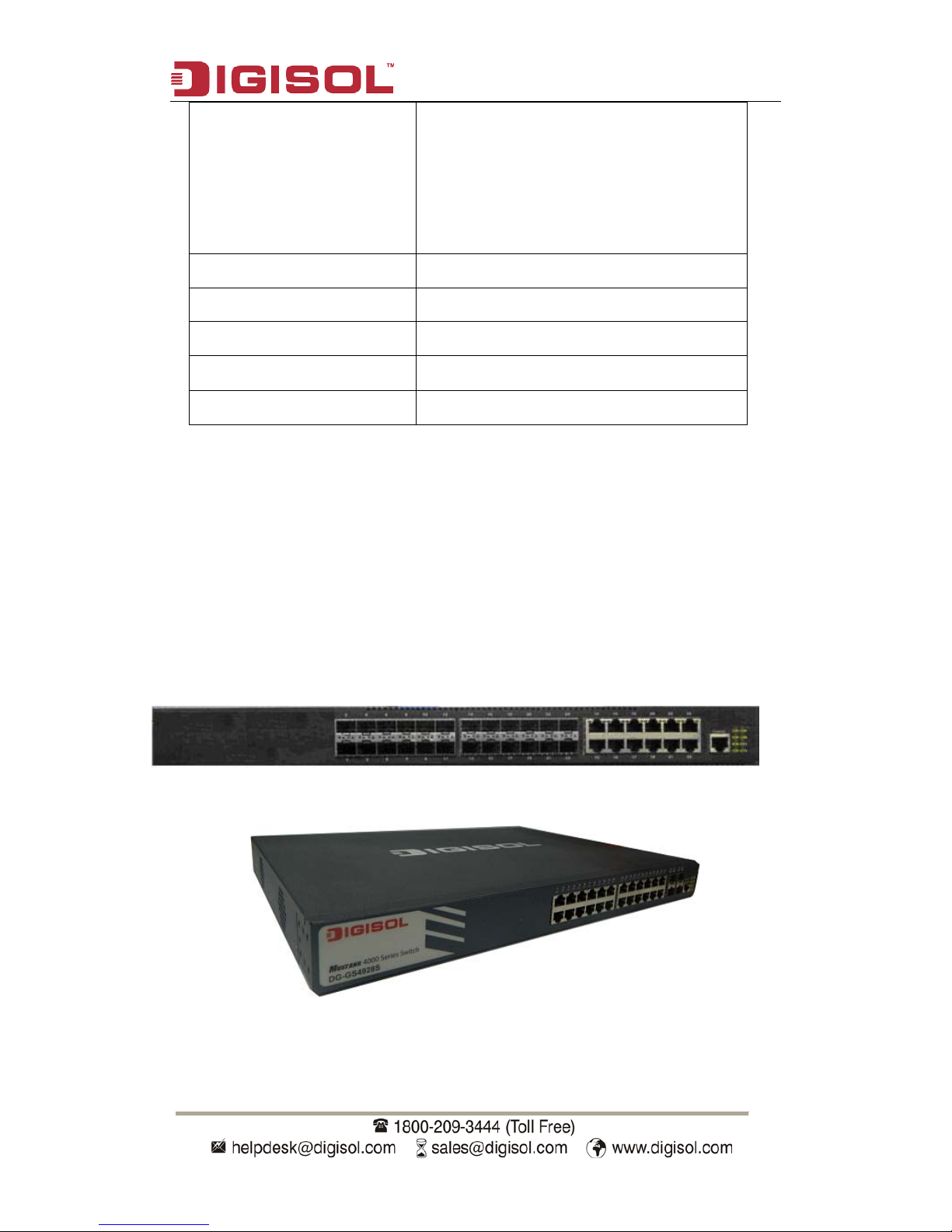
1.4.1 Front Panel
DG-GS4928F Ethernet switch provides 12 1000Mb fiber ports, 12 1000Mb Combo ports,
8 function LEDs and 1 Console port.
Fig 1-1 Front Panel of DG-GS4928F
Fig 1-2 Front Panel of DG-GS4928S
Page 7
DG-GS4900 Series Installation Guide
7
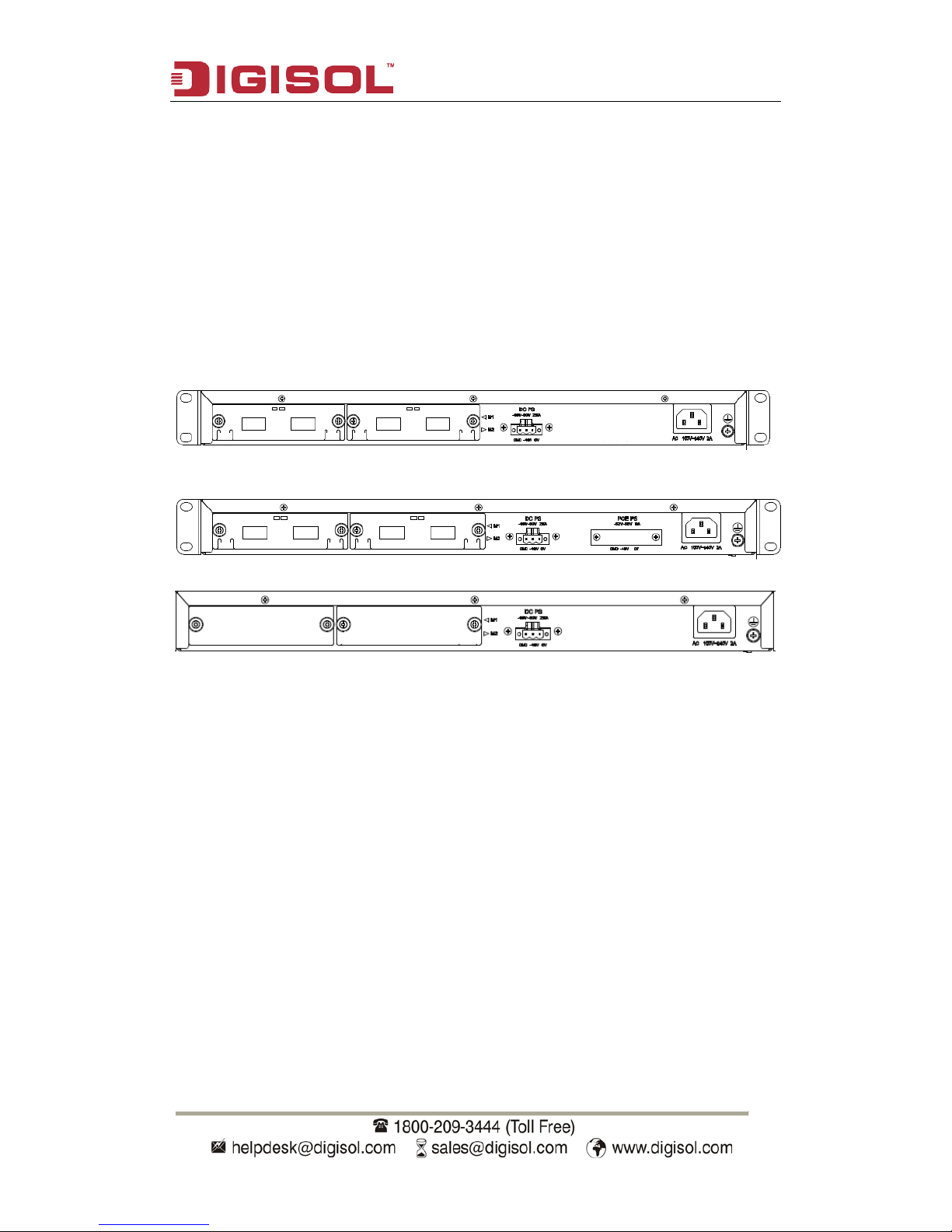
1.4.2 Back Panel
DG-GS4928F / DG-GS4928F / DG-GS4928F -R / suppli es 2 p lug-i n inter face s, 1
-48V DC input power interface, 1 inp ut power interface of PoE and 1 220V input p ower
interface.
DG-GS4928F supp l i es 2 i nt er f ace s w i th t he ext en de d ca r d, 1 interf ace with -48V DC
power input and 1 interf ace with 220V AC power input. Back Panel of DG-GS4928F is
same w ith DG-GS4952F , it sup pli es 2 inter faces for the ext ended c ard, 1 interf ace with
-48V DC power input and 1 interface with 220V AC power input.
Fig 1-3 Back Panel of DG-GS4952F
Fig 1-4 Back Panel of DG-GS4952S
Fig 1-5 Back Panel of DG-GS4928S
Page 8
DG-GS4900 Series Installation Guide
8
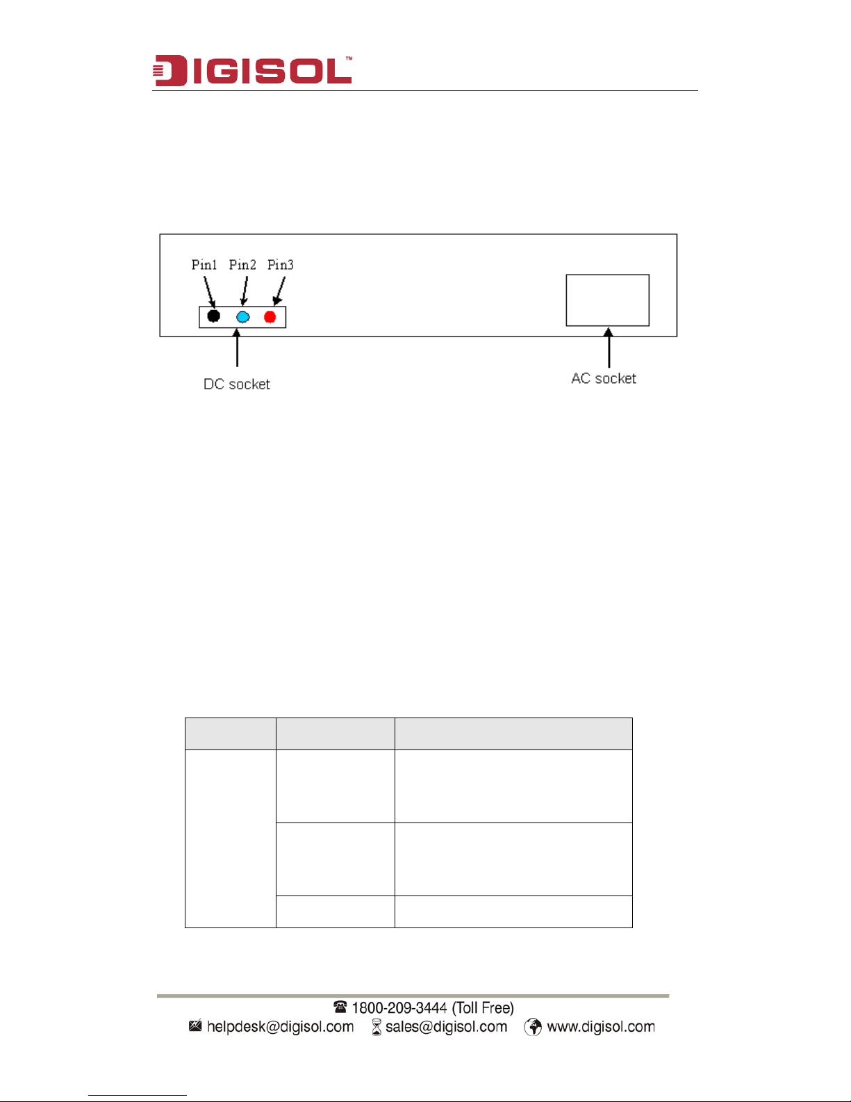
1.4.3 DC Power/PoE Power (specific models only) Input
DG-GS4900 series support AC/DC input power backup and PoE power output.
pin-outs signal of DC power and PoE power are distributed as below:
Fig 1-6 Pin-outs Distribution of DC Input for DG-GS4928F
There are 3 pin-outs for DC socket:
PIN1: GND Ground connection
PIN2: -48V DC power cathode input
PIN3: 0V DC power positive electrode input
1.4.4 Sta t us LE D s
LEDs of DG-GS4928F show the co rrespondi ng state. M ainboard L EDs include two
parts, one is 24/48 1000M inter face LEDs, the y show each port state at RJ45 plug-in,
each port corresponds a LED with double colors.
LED Status Description
Green
On On means p orts are in the l ink state
of 1000M、100M、10M
Off Off means ports are not in the link
state of 1000M、100M、10M
Blink Send or receive the data
Table 1-2 Port LEDs
Page 9

DG-GS4900 Series Installation Guide
9
The other is system LEDs, they are used to show the work status of the system at the
right of front panel.
Panel
Symbol
Status Description
PWR
On (Green) Power is operating normally
Off
Power is abnormally
DIAG
On (Green, blink) System is loading
On (Green)
System is operating normally
ALM
On (Green) System is malfunctioning
Off System is operating normally
RPS
On (Green)
System is using DC power
Off
System does not use DC power
M1
On (Green)
M1 is in place
Off M1 is not in place
M2
On (Green)
M2 is in place
Off
M2 is not in place
Table 1-3 DG-GS4928F System LEDs
LEDs of DG-GS4928F show the corresponding state. There are two kinds of LEDs on
front panel, one of its kinds is fiber/copper LEDs of port transceiver, they are at RJ45 linker
or SFP linker. Each port of RJ45 linker corresponds a LED with double colors, each port of
SFP linker corresponds two LEDs, detailed descriptions are shown in the following tables.
LED Status Description
Green
On It means port is at link state
Off It means port is not at link state
Blink Send or receive the data
Table 1-4 RJ45 Port LEDs
LED Status Description
Left LED
On SFP port is at link state
Off SFP port is not at link state
Blink There is no this state
Page 10

DG-GS4900 Series Installation Guide
10
Right LED
On There is no this state
Off No data is received or sent
Blink Send or receive the data
Table 1-5 SFP Port LEDs
Panel
Symbol
Status Description
PWR
On (Green) Power is operating normally
Off Power is abnormally
DIAG
On (Green, blink) System is loading
On (Green) System is operating normally
ALM
On (Green) System is malfunctioning
Off
System is operating normally
DC
On (Green)
Syste m is using DC power
Off
System does not use DC power
M1-1
On (Green)
Port1 of M1 is at link state
On (Green,
Blink)
Port1 of M1 is rece iving or sendi ng
the data
Off
Port1 of M1 is not at link state
M1-2
On (Green)
Port2 of M1 is at link state
On (Green,
Blink)
Port2 of M1 is rece iving or sendi ng
the data
Off
Port2 of M1 is not at link state
On (Orange)
Port2 of M1 is not at link state, b ut
M1 is in place
M2-1
On (Green)
Port1 of M2 is at link state
On (Green,
Blink)
Port1 of M2 is r eceiving or sending
the data
Off
Port1 of M2 is not at link state
M2-2
On (Green)
Port2 of M2 is at link state
On (Green,
Blink)
Port2 of M2 is r eceiving or sending
the data
Off
Port2 of M2 is not at link state
On (Orange)
Port2 of M2 is not at link stat e, but
M2 is in place
Table 1-6 DG-GS4928F System LEDs
Page 11

DG-GS4900 Series Installation Guide
11
1.4.5 Interface Description of Front Panel
DG-GS4900 series switches provide RJ-45 1000Mb copper port and the interface of
SFP 1000Mb fiber transceivers.
Interface mode Spec
RJ-45 port
• 10/100/1000Mbps auto negotiation
• MDI/MDI-X cable mode auto negotiation
• 5 kinds of UTP: 100 m
SFP
• SFP-SX-L transceiver
1000Base-SX SFP(850nm,MMF,550m)
• SFP-LX-L transceiver
1000Base-LX SFP
Table 1-7 interface descriptions
1.4.6 Extended Module Description
DG-GS4900 series provides 2 slots to install 2
DG-SA-GS4900-2XFP ,DG-SA-GS4900-2SFP+ extended modules.
Extended module
model
DG-GS4900 series swit ch E xtended module
description
DG-SA-GS4900-2XFP Support 10Gb 10Gb XFP extended module
with double ports
DG-SA-GS4900-2SFP+ Support 10Gb 10Gb compatible module with
double ports
DG-SA-GS4900-2SFP Support 1Gb 1Gb compatible module with
double ports
Table 1-8 interface descriptions
Ta ke DG-SA-GS4900-2XFP as an examp le, exten ded m odule diagram is shown as
follows:
Page 12

DG-GS4900 Series Installation Guide
12
Figure 1-5 DG-SA-GS4900-2XFP structure diagram
Each extended module’s panel diagram is shown as follows:
Figure 1-6 p anel diagra m of DG -SA-GS4900-2XFP
Figure 1-7 p anel diagra m of DG-SA-GS4900-2SFP+
Back panel diagrams of switch with extended modules are shown as follows:
Figure 1-8 The back panel with extended modules for DG-GS4928F
Figure 1-9 The back panel with extended modules for DG-GS4952F
Page 13

DG-GS4900 Series Installation Guide
13
Extended module‘s LED descriptions are in the following:
Table 1-9 LED descriptions of 10Gb extended modul e
Spec
XFP
• XFP-SR transceiver
10GBase-SR XFP multi-
mode fiber
transceiver (850nm,62.5μm MMF 32m,50
μ m 500MHz/km MMF 85m , 50 μ m
2000MHz/km MMF 300m)
• XFP-LR transceiver
10GBase-LR XFP single-
mode fiber
transceiver (1310nm,SMF)
SFP+
SFP+-LR transceiver
10GBase-LR SFP+(1310nm, SMF)
SFP+-SR transceiver
10GBase-SR SFP+(850nm, 62.5μm MMF
32m, 50μm 500MHz/km MMF 85m, 50μm
2000MHz/km MMF 300m)
Table 1-10 XFP, SFP+ transceivers descriptions of DG-GS4928F series
LED Status Description
Link/Activity
Green Ports are at link state with 10G
Blink(Green) Ports are at active state with 10G
Off No link or the link is failure
Page 14

DG-GS4900 Series Installation Guide
14
Chapter 2 Hardware Installation
2.1 Installation Notice
To ensure the proper operation for DG-GS4900 series and your physical security,
please read carefully the following installation guide.
2.1.1 Environmental Requirements
• The swi tch m ust b e i nstal l ed i n a cl ean area. Ot her w i se , the switch may be damag ed
by electrostatic adherence.
• Maintain the temperature within 0 to 50 °C and the humidity within 10% to 95%,
non-condensing.
• The sw itch m ust be put i n a dry and co ol p lace. Leav e suffi cient spaci ng around th e
switch for good air circulation.
• The switch m ust w ork i n the r ig ht r ange of power input (AC p ow er: 90 ~ 264V ( 50H z),
DC power: -40 ~ -60V)
• The RPS input of the switch must be in the range of +11.5 ~ +13VDC.
• The switch must be w ell grounded i n ord er to av oi d ESD dam ag e and physi cal i njur y
of people.
• The switch should av oid the sunl ight p erpendi cular inci dence. Keep the sw itch aw ay
from heat sources and strong electromagnetic interference sources.
• The switch must be mounted to a standard 19’’ rack or placed on a clean level
desktop.
2.1.1.1 Dust and Particles
Dust is harmful to the safe operation of DG-GS4928F series. Dust can lead to
electrostatic adherence, especially likely under low relative humidity, causing poor contact
of metal connect ors or contacts. Elect rostatic adher ence will resul t in not only reduced
product lifespan, but also increased chance of communication failures. The recommended
value for dust content and particle diameter in the site is shown below:
Max Diameter (µm)
0.5 1 3 5
Max Density
(particles/m³)
1.4×10⁵ 7×10⁵ 2.4×10⁵ 1.3×10⁵
Table 2-1 Environmental Requirement s: Dust
Page 15

DG-GS4900 Series Installation Guide
15
In addition, salt, acid and sulfide in the air are also harmful to the switch. Such
harmful gases will aggravate metal corrosion and the aging of some parts. The site should
avoid harmful gases, such as SO
2
, H2S, NO2, NH3 and Cl2, etc. The table below details the
threshold value.
Gas Average (mg/m³) Max (mg/m³)
SO2 0.2 1.5
H2S 0.006 0.03
NO2 0.04 0.15
NH3
0.05
0.15
Cl2 0.01 0.3
Table 2-2 Environmental Requirements: Particles
2.1.1.2 Temperature and Humidity
Although the switch is designed to use 4 fans, the site should still maintain a desirable
temperature and humidity. High-humidity conditions can cause electrical resistance
degradation or even electric leakage, degradation of mechanical properties and corrosion
of inter nal co m p onents. Ext r eme low relat iv e humidity may cause the insul ati on space r t o
contract, m aking the f astening screw i nsecure. Further more, in dry env ironments, static
electricity is liable to be produced and cause harm to internal circuits. Temperature
extrem es can cause r educed reli abil ity and prem ature agi ng of insu lation mat erials, thus
reducing the switch’s working lifespan. In the hot summer, it is recommended to use
air-conditioners to cool down the site. And the cold winter, it is recommenced to use
heaters.
The recommended temperature and humidity are shown below:
Temperature: Relative humidity
Long term condition Short term condition Long term condition
Short term
condition
15 ~ 30°C 0 ~ 50°C 40 ~ 65% 10 ~ 95%
Table 2-3 Environmental Requirement s: Temperature a nd Humidity
Caution!
A sample of am bient temp erature and hum idity sh ould be taken at 1.5m abov e the
floor and 0.4m in f r ont of t he sw i tch r ack, w ith no p rot ectiv e panel cov eri ng the f r ont an d
rear of the rack. Short term working conditions refer to a maximum of 48 hours of
Page 16

DG-GS4900 Series Installation Guide
16
continued operation and an annual cumulative total of less than 15 days. Formidable
operation co nditions refers to the ambient temp erature and relativ e humidity value that
may occur during an air-conditioning system failure, and normal operation conditions
should be recovered within 5 hours.
2.1.1.3 Power Supply
Before powering on the power supply , please check the power input to ensure proper
grounding of the power supply syst em. The input source for the switch should b e r el i ab l e
and secure; a v oltage adaptor can be used i f neces sary. The building ’s circui t protecti on
system should include in the circuit a fuse or circuit-breaker of no greater than 240 V, 10 A.
It is recommended to use a UPS for more reliable power supplying. .
Caution!
Improper power supply system grounding, extreme fluctuation of the input power, and
transients (or spikes) can result in larger error rate, or even hardware damage!
2.1.1.4 Preventing Electrostatic Discharge Damage
Static electric discharges can cause damage to internal circuits, even the entire
switch. Follow these guidelines for avoiding ESD damage:
• Ensure proper earth grounding of the device;
• Perform regular cleaning to reduce dust;
• Maintain proper temperature and humidity;
• Always w ear an ESD wrist st rap and antistatic unif orm when in contact w ith circuit
boards.
2.1.1.5 Anti-interference
All sources of interference, whether from the device/system itself or the outside
envir onm ent, w i ll affect op er at i ons i n v arious ways, such as capaci ti ve coupling , induct ive
coupling, electromagnetic radiation, common impedance (including the grounding system)
and cables/l ines (pow er cables, sig nal lines, and outp ut lines). The f ollowi ng should be
noted:
• Precautions should be taken to prevent power source interruptions;
• Provide the system with a dedicated grounding, rather than sharing the grounding with
the electronic equipment or lightning protection devices;
• Keep away from high power radio transmitters, radar transmitters, and high frequency
strong circuit devices;
Page 17

DG-GS4900 Series Installation Guide
17
• Provide electromagnetic shielding if necessary.
2.1.1.6 Rack Configuration
The dim ensions of the D G-GS4900 series is desig n ed to b e m ounted on a sta ndard
19’’ rack, please ensure good ventilation for the rack.
• Every dev ice in the r ack will g enerate heat dur ing o perati on, therefor e vent and f ans
must be provided for an enclosed rack, and devices should not be stacked closely.
• When m ounting dev ices i n an open rack, c are should be t aken to prev ent the rack
frame from obstructing the switch ventilation openings. Be sure to check the
positioning of the switch after installation to avoid the aforementioned.
Caution!
If a standar d 19’’ rack is not av ailable, t he DG-GS4900 ser ies can be p laced on a
clean level desktop, leave a clearance of 100mm around the switch for ventilation, and do
not place anything on top of the switch.
2.1.2 Installation Notice
• Read through the installation instruction carefully before operating on the system.
Make sure the installation materials and tools are prepared. And make sure the
installation site is well prepared.
• During the installation, users must use the brackets and screws provided in the
accessory kit. Users should use the proper tools to perform the installation. Users
should always wear antistatic uniform and ESD wrist straps. Users should use
standard cables and connecters.
• After the installation, users should clean the site. Before powering on the switch, users
should ensure the switch is well grounded. Users should maintain the switch regularly
to extend the lifespan of the switch.
2.1.3 Security Warnings
• When usi ng SF P transce iver, do not stare direct ly at the fiber bore when the sw i t ch i s
in operation. Otherwise the laser may hurt your eyes.
• Do not attem pt t o conduct th e op erati ons w hich can dam age t he swi tch or which can
cause physical injury.
• Do not install, move or disclose the switch and its modules when the switch is in
operation.
• Do not open the switch shell.
Page 18

DG-GS4900 Series Installation Guide
18
• Do not drop metals into the switch. It can cause short-circuit.
• Do not touch the power plug and power socket.
• Do not place the tinder near the switch.
• Do not configure the switch alone in a dangerous situation,
• Use standard power sockets which have overload and leakage protection.
• Inspect and maintain the site and the switch regularly.
• Have the em erg ence pow er swit ch on the site. I n case of emer gence, sw itch off the
power immediately.
Caution!
Potential risk include: Electr ic leakage, Pow er supply arcing, Pow er line breakag e,
Imperfect earth, Overload circuit and Electrical short circuit. If electric shock, fire, electrical
short circuit occurs, please cut off the electricity supply and alarm rapidly. Rescue the
injured p erson in the co ntingency und er inherentl y safe, give the injur ed person pr oper
first aid treatment according to the injury state, and seek help from the Medical
Emergency using various ways.
2.2 Installation Preparation
2.2.1 Verify the Package Contents
Please unpack the shipping package and verify carefully the contents inside.
2.2.2 Required Tools and Utilities
The required tools and utilities are shown below:
• Cross screwdrivers
• Flat-blade screwdriver
• ESD wrist strap
• Antistatic uniform
Caution!
Users should prepare the required tools by themselves.
Page 19

DG-GS4900 Series Installation Guide
19
2.3 Installation Guide
2.3.1 Installing Switch
Fig 2-1 Install sketch map on the rack
Please mount DG-GS4900 series on the 19’’ rack as below:
1. Attach the 2 brackets on the DG-GS4900 series with screws provided in the
accessory kit.
2. Put the bracket-mounted switch smoothly into a standard 19’’ rack. Fasten the
DG-GS4928F series to the rack w ith the screws p rovided. Leav e enough space around
the switch for good air circulation.
Caution!
The bracke ts are used to f ix the sw itch on the rack. They can’t ser ve as a bear ing.
Please place a rack shelf under the switch. Do not place anything on top of the switch. Do
not block the blowholes on the switch to ensure the proper operation of the switch.
2.3.2 Connecting Console
DG-GS4900 series provides a Mini-USB serial console port.
Page 20

DG-GS4900 Series Installation Guide
20
Fig 2-2 Connecting Cons ole to switch
The connection procedure is shown below:
1. Find the console cable provided in the accessory kit. Attach the Mini-USB end to
console port of the switch.
2. Connect the other side of the console cable to a character terminal (PC).
3. Pow er on the switch and the character terminal. Configure the switch through the
character terminal.
2.3.3 SFP Transceiver Installation
DG-GS4900 series provides multiple 1000Mb SFP transceiver slots.
The procedure for installing SFP transceiver is shown below:
Step 1: Put on a ESD wrist strap (or antistatic gloves).
Step 2: Insert SF P transcei v er to the g uide rai l i nside the f i ber inter face line ca rd. D o not
put the SFP transceiver up-side-down.
Step 3: Push SFP transceiver along the guide rail gently until you feel the transceiver snap
into place at the bottom of the line card.
Note: SFP transceiver supports the hot swap.
Caution!
Do not stare directly at the 2 fiber bores in the SFP transceiver when the switch is in
operation, otherwise the laser may hurt your eyes.
Page 21

DG-GS4900 Series Installation Guide
21
2.3.4 DG-SA-GS4900-2XFP Extended Module Installation
DG-GS4900 series provide 10Gb slots. The procedure for installing the
DG-SA-GS4900-2XFP module and the XFP 10Gb fiber transceiver is shown below:
Step 1: Put on an ESD wrist strap (or antistatic gloves).
Step 2: Insert the DG-SA-GS4900-2XFP modul e t o t he g ui de r ai l i nsi de t he 1 0Gb module
slot.
Step 3: Push the D G-SA-GS4900-2XFP module al ong the g uide r ail g entl y unt il i t com es
into contact with the machine panel.
Step 4: Insert t he XFP transc eiv er to the guide r ail i nside t he DG-SA-GS4900-2XFP. D o
not put the XFP transceiver up-side-down.
Step 5: Push the XFP transceiver along the guide rail gently until it comes into contact with
the DG-SA-GS4900-2XFP.
Note: the XFP 10Gb fiber transceiver is hot swappable.
2.3.5 DG-SA-GS4900-2SFP+ extended module Installation
DG-GS4900 series provide 10Gb slots. The procedure for installing
theDG-SA-GS4900-2SFP+module and the SFP+ 10Gb fiber transceiver is shown below:
Step 1: Put on an ESD wrist strap (or antistatic gloves).
Step 2: Insert theDG-SA-GS4900-2SFP+module to the gui de r ai l i nsi de t he 10Gb module
slot.
Step 3: Push theD G-SA-GS4900-2SFP+ module along the g ui de r ai l g ent ly until it co mes
into contact with the machine panel.
Step 4: Insert the SFP+ transceiver to the guide rail inside the DG-SA-GS4900-2SFP+.Do
not put the XFP transceiver up-side-down.
Step 5: Push the SFP+ tra nsceiv er along the guide rail g ently unti l it com es i nto contact
with the DG-SA-GS4900-2SFP+
Caution!
Do not star e directly at the 2 fiber bores in t he fiber t ransceiver w hen the switch is in
operation, otherwise the laser may hurt your eyes.
Page 22

DG-GS4900 Series Installation Guide
22
2.3.6 Copper Cable/Fiber Cable Connection
Copper cables should be connected as below:
Step 1: Insert one end of the Ethernet cable to the RJ-45 Ethernet port in the copper cable
line card of the switch;
Step 2: Insert the other end of the Ethernet cable to the RJ-45 Ethernet port of other
device;
Step 3: Check all status indicators for the corresponding ports; a lighted LED indicates that
the link has been established, o therwise the l ink is not ready an d the cable shoul d be
examined.
Caution!
Please ver ify the sig n above the p ort to ensur e the rig ht port used. C onnecting to w rong
ports might damage the switch.
Fiber cables should be connected as below:
Step 1: Remove the protective plug from the SFP/XFP/SFP+ fiber transceiver bore;
Remov e the p r ot ecti ve cap f r om one end of t h e f i ber cable. Ke ep the fiber end clean and
neat.
Step 2: Attach one end of the fiber cable to the SFP/XFP/SFP+ transceiver, and attach the
other end to the transceiver of the corresponding devices. Note: The SFP/XFP/SFP+
transceiver’s TX port should be connected to the RX port of the corresponding device, and
vice versa.
Step 3: Check the fiber port status indicator, a lighted LED indicates that the link has been
established; otherwise the link is not ready and should be examined.
Caution!
Please verify the sign above the port to ensure using the other ports. Connecting to wrong
ports m ight damage the transceiver or the other ports. When connect ing other device s
through a fiber cable to the switch, the output power of the fiber cable must not exceed the
maximum r eceived power of the cor responding modules. Ot herwise, it wil l damage the
fiber t ransce iver. Do not stare at the f ib er bore when t he sw itch is in op erati on. That m ay
hurt your eyes.
Page 23

DG-GS4900 Series Installation Guide
23
2.3.7 AC Power Supply Connection
DG-GS4900 ser ies switches use 220V AC pow er suppl y by def ault. Pl eas e read t he
power input specification for the detailed information.
AC Power supply connection procedure is described as below:
1. Insert one end of the p ow er ca bl e provi ded in the acce sso r y kit in to the pow er source
socket (w ith ov erload and l eakag e protect ion), and the other end to th e pow er socke t in
the back panel of the switch.
2. Check the p ower status indica tor in the front pa nel of the sw itch. The corresp onding
power indicator should light. DG-GS4900 series is self-adjustable for the input voltage. As
soon as the input voltage is in the range pr inted on the switch surface, the switch can
operate correctly.
3. When the switch is powered on, it executes self-test procedure and startups.
Caution!
The input voltage must be within the required range, otherw ise the switch can be
damaged or malfunct ion. Do not open the sw itch shel l without permissi on. It can ca use
physical injury.
Page 24

DG-GS4900 Series Installation Guide
24
2.3.8 DC Power Supply Connection
DG-GS4900 series supports 220V AC input, 48V DC input or 220V AC, 48V DC input
simultaneously. 48V DC input connection procedure is described as below:
1. Insert DC power linker provided in the accessory kit into DC power source socket in the
back panel of the switch.
2. Check whether the power status indicator is light in the front panel of the switch.
3. When the switch is powered on, it executes self-test procedure and startups.
Caution!
The input voltage must be within the required range, otherwise the switch can be
damaged or malfunction. PoE power supply of the front port is disabled when the switch is
power-off or is not starte d. If there is any problem, do not open the sw itch shell without
permission. It can cause physical injury .
This product comes with Life time warranty. For further details
about warranty policy and Product Registration, please visit
support section of
www.smartlink.co.in
 Loading...