

Page 1
DG-GS4600 SERIES
24/48 PORT ACCESS LAYER 3 SWITCH
Installation Guide
V1.0
2013-05-22
As our products undergo continuous development the specifications are subject to change without prior notice
Page 2

Content
2
Content
Chapter 1 Introduction ........................................................... 1-1
1.1 Product Brief ................................................................................... 1-1
1.2 Physical Specifications .................................................................. 1-2
1.3 Description of Hardware ................................................................ 1-3
1.3.1 Front Panel...............................................................................................1-3
1.3.2 Back Panel ...............................................................................................1-4
1.3.3 Status LEDs .............................................................................................1-5
1.3.4 Front P anel Port Description .................................................................1-9
Chapter 2 Hardware Installation ........................................... 2-1
2.1 Installation Notice ........................................................................... 2-1
2.1.1 Environmental Requirements ................................................................2-1
2.1.2 Installation Notice ...................................................................................2-4
2.1.3 Security Warnings ...................................................................................2-5
2.2 Installation Preparation .................................................................. 2-5
2.2.1 Verify the Package Contents ..................................................................2-5
2.2.2 Required Tools and Utilities ...................................................................2-6
2.3 Installation Guide ............................................................................ 2-6
2.3.1 Installing the Switch ...............................................................................2-6
2.3.2 Conne cting Console ...............................................................................2-7
2.3.3 SFP Transceiver Installation ..................................................................2-8
2.3.4 Coppe r Cable/Fiber Cable Connection .................................................2-8
2.3.5 Power Supply Connection .....................................................................2-9
Page 3
Introduction
1-1
Chapter 1 Introduction
1.1 Product Brief
DG-GS4600 series switch are 100Mb and 1000Mb uplink layer 2 switches.
DG-GS4600 series switch include: DG-GS4610*, DG-GS4628, DG-GS4652* and
DG-GS4628HP*. DG-GS4610 has 12 fixed po rts ( 8 10/100/1000Base-T f ixed p or ts and 2
1000Mb COMBO ports). DG-GS4628 has 30 fixed ports (24 10/100/1000Base-T f ixed
ports, 2 1000M b COM BO ports and 2 10 00Mb optical p orts). DG-GS4652 has 52 fixed
ports (48 10/100/1000Base-T fixed ports and 4 1000Mb optical ports). DG-GS4628HP has
30 fixed ports (24 10/100/1000Base-T fixed ports, 2 1000Mb COMBO ports and 2 1000Mb
optical ports), i t also supports 24 1000M b PoE power supp ly. DG-GS4600 series switch
with advanced intelligent and secure features, can serve ideally as distribution layer
switches for the 1000M b input dev ice of ca mpus netw orks, enterpr ise networks and IP
metropolitan networks.
DG-GS4610:
Fig 1-1 DG-GS4610 switch
DG-GS4628:
Fig 1-2 DG-GS4628 switch
Page 4
Introduction
1-2
Note (*): DG-GS4600 Series, currently only includes DG-GS4628 model. DG-GS4610,
DG-GS4652 and DG-GS4628HP switches will be available in Future hardware release.
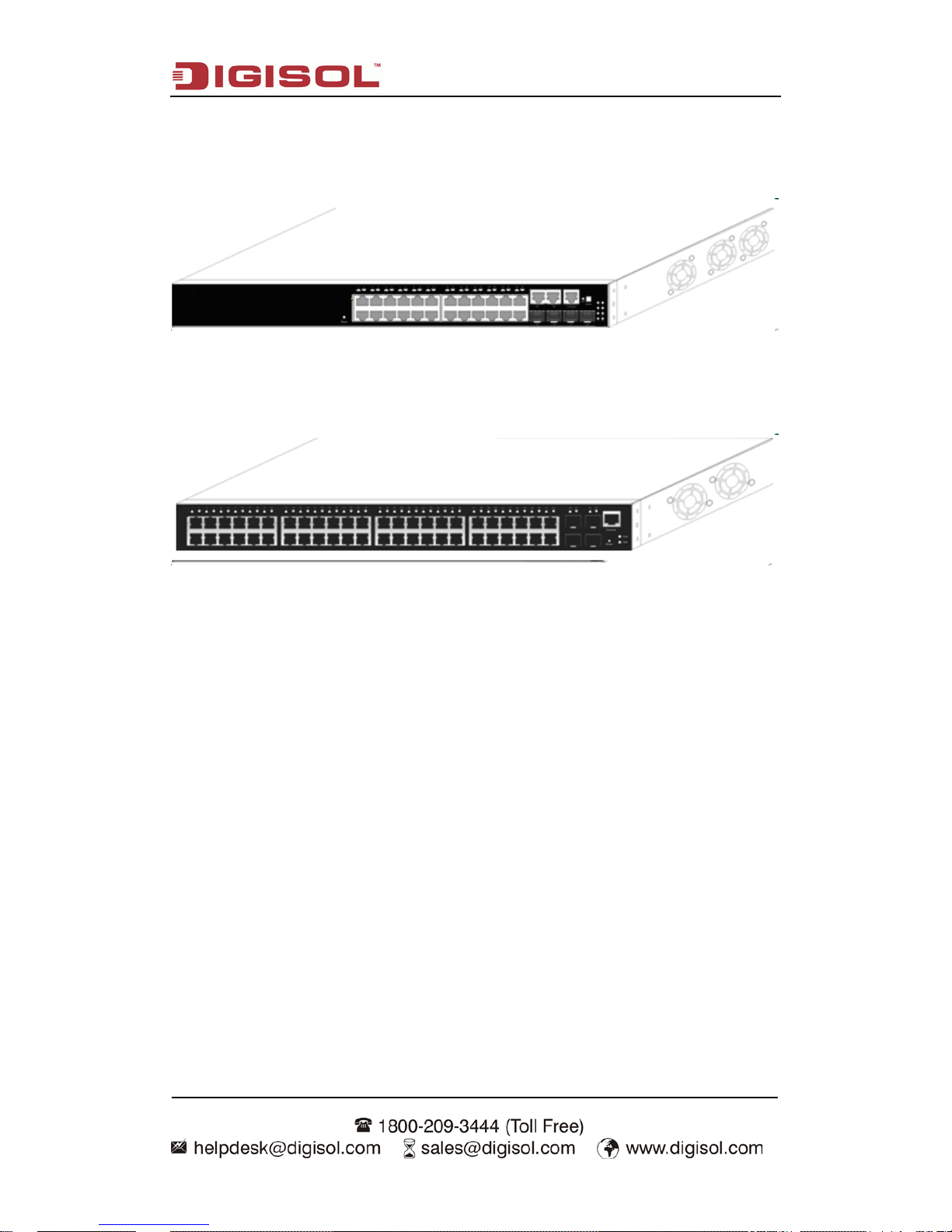
DG-GS4628HP:
Fig 1-3 DG-GS4628HP switch
DG-GS4652:
Fig 1-4 DG-GS4652 switch
1.2 Physical Specifications
Management Port
1 RJ-45 serial console port
AC/DC Power Input
AC: 100 ~ 240VAC,50 ~ 60Hz
Power Consumption
DG-GS4610: 20W Max
DG-GS4628: 42W Max
DG-GS4652: 60W Max
DG-GS4628HP: 450W Max
Operating Temperature
-5°C ~ 50°C
Storage Temperature
-40°C ~ 70°C
Page 5
Introduction
1-3
Relative Humidity
5% ~ 95%, no condensate
Dimension
DG-GS4610: 330mm×44mm×204mm ( W * H * D)
DG-GS4628: 440mm×44mm×230mm (W * H * D)
DG-GS4652: 440mm×44mm×220mm (W * H * D)
DG-GS4628HP: 440mm×44mm×410mm (W * H * D)
1.3 Description of Hardware
1.3.1 Front Panel
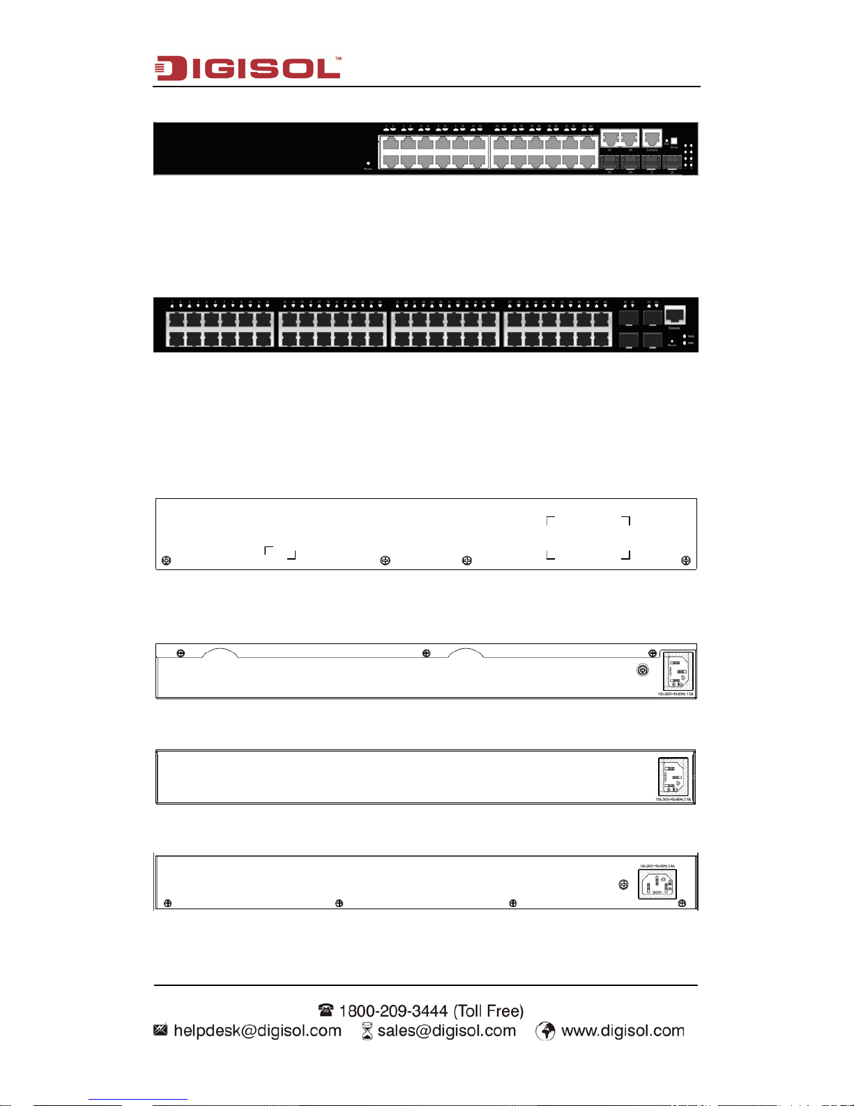
DG-GS4610 has 8 10/100/1000Base-T ports, 2 Combo ports (2 RJ-45 and 2 SFP), 1
Console port, 1 USB port, 14 LEDs and 1 220V AC power socket.
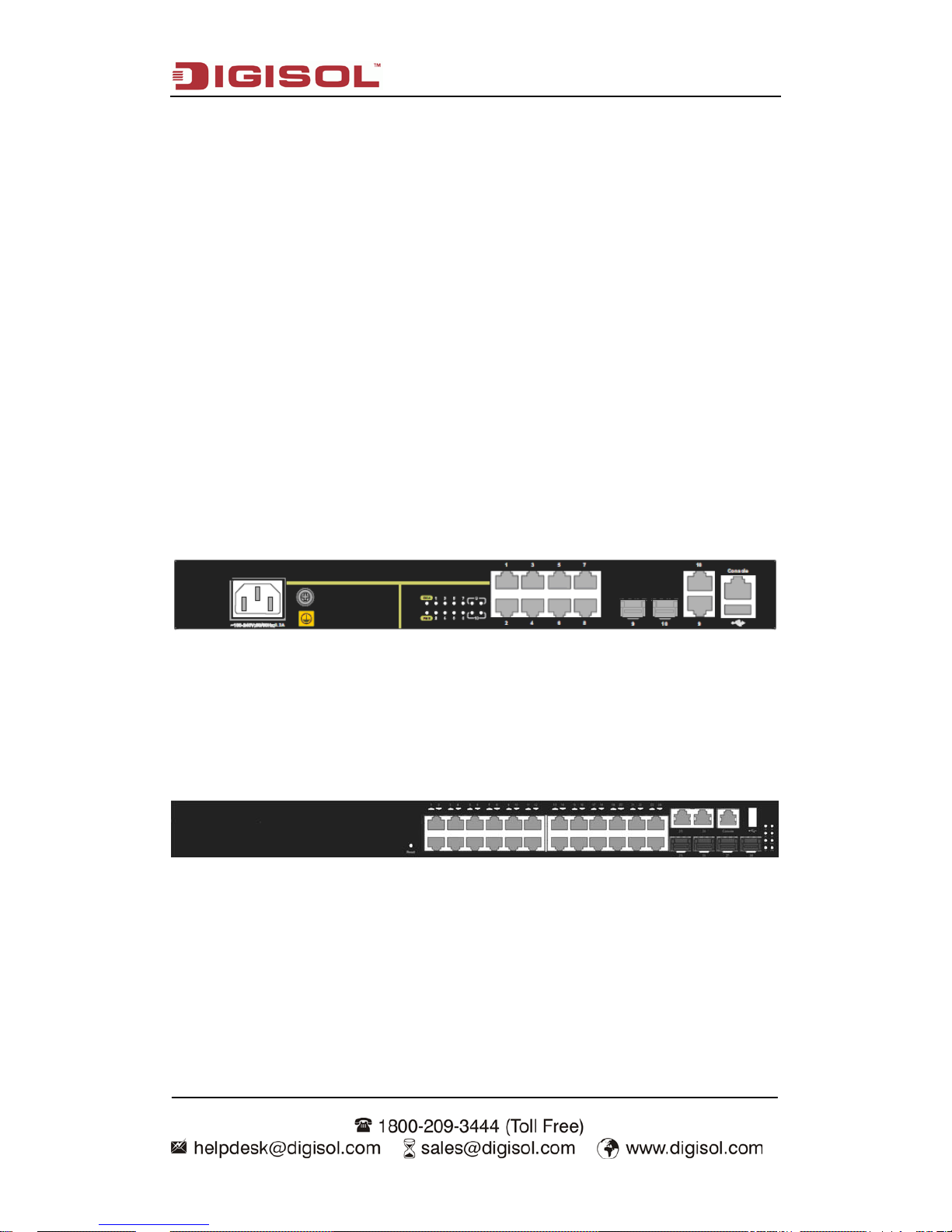
The front panel of DG-GS4610 is shown below:
Fig 1-5 Front Panel of DG-GS4610
DG-GS4628 has 24 10/100/1000Base-T ports, 2 Combo ports (2 RJ-45 and 2 SFP),
2 SFP optical ports, 1 Console port and 32 LEDs.
The front panel of DG-GS4628 is shown below:
Fig 1-6 Front Panel of DG-GS4628
DG-GS4628HP has 24 10/100/1000Base-T ports, 2 Combo ports (2 RJ-45 and 2
SFP), 2 SFP optical ports, 1 Console port and 32 LEDs.
Page 6
Introduction
1-4
The front panel of DG-GS4628HP is shown below:
Fig 1-7 Front Panel of DG-GS4628HP
DG-GS4652 has 48 10/100/1000Base-T ports, 4 SFP optical ports and 52 LEDs.
The front panel of DG-GS4652 is shown below:
Fig 1-8 Front Panel of DG-GS4652
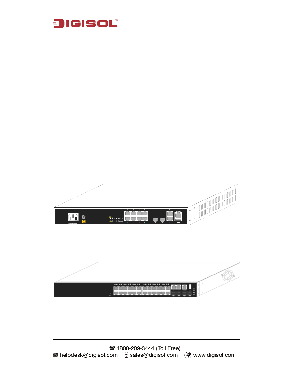
1.3.2 Back Panel
The back panel of DG-GS4610 is shown below:
Fig 1-9 Back Panel of DG-GS4610
DG-GS4628, DG-GS4628HP and DG-GS4652 have 1 220V AC power receptacle.
Fig 1-10 Back Pan el of DG-GS4628
Fig 1-11 Back Panel of DG-GS4628HP
Fig 1-12 Back Pan el of DG-GS4652
Page 7
Introduction
1-5
1.3.3 Status LEDs
DG-GS4600 series include port indications and system status indication. Their status
meanings are shown below.
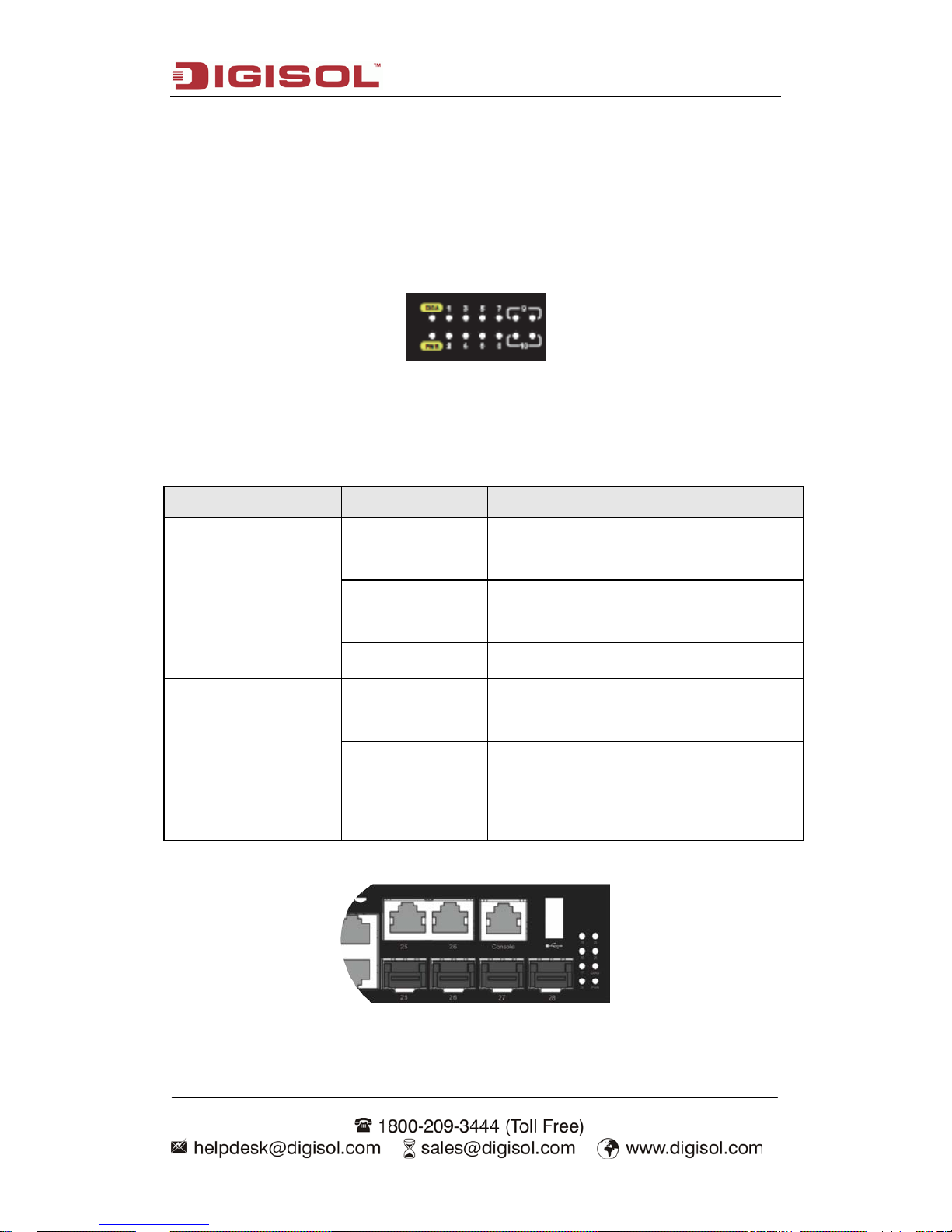
1.3.3.1 Port indication Description
Fig 1-13 DG-GS4610 LED diagram
Table 1-1 DG-GS4610 port indications description
Panel Symbol Status Description
Port1-10(Link/Act)
On (Green)
ports are in successful link state of 10M,
100M or 1000M
Flash(Green)
ports are in successful link state and
receive/send data
Off
ports are not in link
SFP9-10
On (Green)
ports are in successful link state of 10M,
100M or 1000M
Flash(Green)
ports are in successful link state and
receive/send data
Off ports are not in link
Fig 1-14 DG-GS4628 LED diagram
Page 8

Introduction
1-6
Table 1-2 DG-GS4628 port indications description
Panel Symbol Status Description
GE Port1-24(Link/Act)
On (Green)
ports are in successful link state of 10M,
100M or 1000M
Flash(Green)
ports are in successful link state and
receive/send data
Off ports are not in link
Port25/26
COPPER(Link/Act)
On (Green)
ports are in successful link state of 10M,
100M or 1000M
Flash(Green)
ports are in successful link state and
receive/send data
Off
ports are not in link
Port25/26
SFP(Link/Act)
On (Green)
ports are i n successful l ink state of 100M or
1000M
Flash(Green)
ports are in successful link state and
receive/send data
Off
ports are not in link
Port27/28
SFP(Link/Act)
On (Green)
ports are i n successful l ink state of 100M or
1000M
Flash(Green)
ports are in successful link state and
receive/send data
Off ports are not in link
Fig 1-15 DG-GS4628HP LED diagram
Page 9

Introduction
1-7
Table 1-3 DG-GS4628HP port indications description
Panel Symbol Status Description
GE Port1-24(Link/Act)
On (Green)
ports are in successful link state of 10M,
100M or 1000M
Flash(Green)
ports are in successful link state and
receive/send data
Off ports are not in link
Port25/26
COPPER(Link/Act)
On (Green)
ports are in successful link state of 10M,
100M or 1000M
Flash(Green)
ports are in successful link state and
receive/send data
Off
ports are not in link
Port25/26
SFP(Link/Act)
On (Green)
ports are i n successful l ink state of 100M or
1000M
Flash(Green)
ports are in successful link state and
receive/send data
Off
ports are not in link
Port27/28
SFP(Link/Act)
On (Green)
ports are i n successful l ink state of 100M or
1000M
Flash(Green)
ports are in successful link state and
receive/send data
Off ports are not in link
Port1/24 POE(Link/Act)
On (Green) PD connection is successful.
Flash(Green)
PD connection is successful and
receive/send data
Off No PD connection
Page 10

Introduction
1-8
Fig 1-16 DG-GS4652 LED diagram
Table 1-4 DG-GS4652
port indications description
Panel Symbol Status Description
GE Port1-48(Link/Act)
On (Green)
ports are in successful link state of 1000M
Flash(Green)
ports are i n successful li nk state of 1000M
and receive/send data
On (Yellow)
ports are i n successful l ink state of 10M or
100M
Flash(Yellow)
ports ar e in successful link state of 10M or
100M and receive/send data
Off ports are not in link
GE Port49-52(Link/Act)
On (Green)
ports are in successful link state of 1000M
Flash(Green)
ports are i n successful li nk state of 1000M
and receive/send data
On (Yellow)
ports are in successful link state of 100M
Flash(Yellow)
ports are in successful link state of 100M
and receive/send data
Off ports are not in link
1.3.3.2 System Status Indication Description
Table 1-5 system indication description
Panel Symbol Status Description
Power On (Green) The internal power is operating normally
Page 11

Introduction
1-9
Off Power is off or error
DIAG
Green light
winks fast
Operating status is normal
Green light
winks slo wly
System is in loading
1.3.3.3 PoE Indication Description
Table 1-6 DG-GS4628HP Button description
Button stat us Port LED status POE LED
B
utton is not
pressed
Show port Link/Act
status
Not enabled
B
utton is
pressed
Show port POE status Enabled POE status
Table 1-7 DG-GS4628HP PoE indi ca tion description
LED Status Description
PoE
Green Port is in power state.
Flash(Green) POE is in maximum power state.
Off Port power is not supplied.
1.3.4 Front Panel Port Description
Each port description is shown below:
Table 1-8 DG-GS4600 por t description
Interface mode Spec
RJ-45 port
• 10/100/1000Mbps auto negotiation
• MDI/MDI-X cable mode auto negotiation
5 kinds of UTP: 100 m
Combo electrical port supports 10/100/1000Mbps auto
negotiation
SFP
SFP-SX-L transceiver
Page 12

Introduction
1-10
1000Base-SX SFP (850nm, MMF, 550m)
SFP-LX-L transceiver
1000Base-LX SFP int er f ace ca r d module (1310nm, SMF, 10km
or MMF, 550m)
SFP-LX-20-L transceiver
1310nm light waves, 9/125um single mode fiber: 20km
SFP-LX-40 transceiver
9/125um single mode fiber: 40km
SFP-LH-70-L transceiver
9/125um single mode fiber: 70km
SFP-LH-120-L transceiver
9/125um single mode fiber: 120km
SFP-GT
SFP-GT module:
1000Base-T SFP interface card module, RJ-45 port
SFP-FX
SFP-FX : 100Base-FX SFP
interface card module
(1310nm, MMF, 2KM), LC interface
SFP-FL : 100Base-FL SFP interface card module (1310nm,
SMF, 15KM), LC interface
SFP-FL-40 : 100Base-FL SFP interface card module
(1310nm, SMF, 40KM), LC interface
SFP-FL-80 : 100Base-FL SFP
interface card module
(1550nm, SMF, 80KM), LC interface
Page 13

Hardware Installation
2-1
Chapter 2 Hardware Installation
2.1 Installation Notice
To ensure the proper operation of DG-GS4600 series and your physical security,
please read carefully the following installation guide.
2.1.1 Environmental Requirements
The switch must be installed in a clean area. Otherwise, the switch may be damaged
by electrostatic adherence.
Maintain the temperature within 0 to 50 °C and the humidity within 5% to 95%,
non-condensing.
The swi tch m ust b e put i n a dry and cool pl ace. Leav e su ffici ent spaci ng around the
switch for good air circulation.
The swi tch must wor k in the right r ange of p ower input (AC power: 100 ~
240VAC
(
50/60Hz))
The switch m ust b e w el l grounded i n order to av oi d ESD damage and physica l i nj ur y
of people.
The switch should av oi d the sunli ght perp endicul ar inci dence. K eep the switch aw ay
from heat sources and strong electromagnetic interference sources.
The switch must be mounted to a standard 19’’ rack or placed on a clean level
desktop.
2.1.1.1 Dust and Particles
Dust is harmful to the safe operation of DG-GS4600 series. Dust can lead to
electrostatic adherence, especially likely under low relative humidity, causing poor contact
of m etal connectors or co ntacts. Electrostatic ad herence will result in not only reduc ed
product lifespan, but also increased chance of communication failures. The recommended
value for dust content and particle diameter in the site is shown below:
Max Diameter (µm) 0.5 1 3 5
Max Density (particles/m³) 1.4×10⁷ 7×10⁵ 2.4×10⁵ 1.3×10⁵
Table 2-1Environmental Requirements: Dust
Page 14

Hardware Installation
2-2
In addition, salt, acid and sulfide in the air are also harmful to the switch. Such
harmful gases will aggravate metal corrosion and the aging of some parts. The site should
avoid harmf ul gases, such as SO
2
, H2S, NO2, NH3 and C l2, etc. The table b elow details
the threshold value.
Gas
Average (mg/m³)
Max (mg/m³)
SO2 0.2 1.5
H2S 0.006 0.03
NO2 0.04 0.15
NH3 0.05 0.15
Cl2 0.01 0.3
Table 2-2 Environmental Requirements: Particles
2.1.1.2 Temperature and Humidity
The switch install site should maintain a desirable temperature and humidity.
High-humidity conditions can cause electrical resistance degradation or even electric
leakage, degradation of mechanical properties and corrosion of internal components.
Extrem e low relative humidi ty may cause the insul ation spacer to contr act, making the
fastening screw insecure. Furthermore, in dry environments, static electricity is liable to be
produced a nd c ause har m to int er nal ci rcui ts. Temperature extrem es can cause reduc ed
reliab ility and p rem atur e agi ng of insul ation m ater ials, thus red uci ng the switch’s w orking
lifespan. In the h ot summ er, it is recommended to use ai r-conditi oners to cool dow n the
site. And the cold winter, it is recommenced to use heaters.
The recommended temperature and humidity is shown below:
Temperature: Relative humidity
Long term condition Short term condition Long term condition
Short term
condition
15 ~ 30°C 0 ~ 50°C 40 ~ 65% 5 ~ 95%
Table 2-3 Environmental Requirements: Temperature and Humidity
Caution!
A sample of am bient temp erature and hum idity sho uld be taken at 1.5m ab ove the
floor and 0. 4m i n fr ont of the sw it ch rack, wi th no pr otect iv e panel cov er ing the f ront a nd
Page 15

Hardware Installation
2-3
rear of the rack. Short term working conditions refer to a maximum of 48 hours of
continued operation and an annual cumulative total of less than 15 days. Formidable
operation co nditions refers to the ambient temper ature and relat ive humidit y value that
may occur during an air-conditioning system failure, and normal operation conditions
should be recovered within 5 hours.
2.1.1.3 Power Supply
It is adop ted module sw itch power for the switch; the inp ut parameter of p ower is
shown below:
The AC input voltage: 100~240VAC
The frequency: 50~60Hz
Before powering on the power supply, please check the power input to ensure proper
grounding of the pow er supply system . The i np ut source for the switch shoul d b e r el i able
and secure; a voltage adaptor can be used if necessary . The building’s circuit protection
system should include in the circuit a fuse or circuit-breaker of no greater than 240 V, 10 A.
It is recommended to use a UPS for more reliable power supplying. .
Caution!
Improper power supply system grounding, extr eme f luctuation of the i nput source,
and transients (or spikes) can result in larger error rate, or even hardware damage!
2.1.1.4 Preventing Electrostatic Discharge Damage
Static electric discharges can cause damage to internal circuits, even the entire
switch. Follow these guidelines for avoiding ESD damage:
Ensure proper earth grounding of the device;
Perform regular cleaning to reduce dust;
Maintain proper temperature and humidity;
Always w ear an ESD wrist strap and antistatic uniform when i n contact with ci rcuit
boards.
Page 16

Hardware Installation
2-4
2.1.1.5 Anti-interference
All sources of interference, whether from the device/system itself or the outside
environment, will affect operations in various ways, such as capacitive coupling, inductive
coupling, electromagnetic radiation, common impedance (including the grounding system)
and cables/l ines (pow er cables, signal lines, and output lines). The f ollowing shoul d be
noted:
Precautions should be taken to prevent power source interruptions;
Provide the system wi th a dedicated grounding , rather than shar ing the grounding
with the electronic equipment or lightning protection devices.
Keep away from high power radio transmitters, radar transmitters, and high frequency
strong circuit devices.
Provide electromagnetic shielding if necessary.
2.1.1.6 Rack Configuration
The dimensions of the DG-GS4600 series are designed to be mounted on a standard
19’’ rack. Please ensure good ventilation for the rack.
Every dev ice in the r ack w ill gener ate hea t duri ng op erati on, ther efor e v ent and f ans
must be provided for an enclosed rack, and devices should not be stacked closely.
When mount ing devi ces in an op en rack, car e shoul d be taken to prevent the rack
frame from obstructing the switch ventilation openings. Be sure to check the
positioning of the switch after installation to avoid the aforementioned.
Caution!
If a standar d 19’’ rack is not av ailable, the DG-GS4600 seri es can be placed on a
clean level desktop, leave a clearance of 100mm around the switch for ventilation, and do
not place anything on top of the switch.
2.1.2 Installation Notice
Read throug h the installation instruction carefully before operating on the system.
Make sure the installation materials and tools are prepared. And make sure the
installation site is well prepared.
During the installation, users must use the brackets and screws provided in the
accessory ki t. Users should use the proper tools to perform the install ation. Users
should always wear antistatic uniform and ESD wrist straps. Users should use
Page 17

Hardware Installation
2-5
standard cables and connecters.
After the installation, users should clean the site. Before powering on the switch,
users shoul d ensure th e swit ch is well grounded. U sers should m aintain the switch
regularly to extend the lifespan of the switch.
2.1.3 Security Warn ings
When using SFP transceiver, do not stare directly at the fiber bore when the switch is
in operation. Otherwise the laser may hurt your eyes.
Do not attem p t t o conduct the operations which can dam ag e t he sw i tch or w hi ch ca n
cause physical injury.
Do not install, move or disclose the switch and its modules w hen the switch is in
operation.
Do not open the switch shell.
Do not drop metals into the switch. It can cause short-circuit.
Do not touch the power plug and power socket.
Do not place the tinder near the switch.
Do not configure the switch alone in a dangerous situation,
Use standard power sockets which have overload and leakage protection.
Inspect and maintain the site and the switch regularly.
Have the em er gence pow er switch on the si te. I n c ase of em erg ence, switch off the
power immediately.
Caution!
Potential risk include: Electric l eakage, Pow er supply ar cing, Pow er line breakag e,
Imperfect earth, Overload circuit and Electrical short circuit..If electric shock, fire, electrical
short circuit occurs, please cut off the electricity supply and alarm rapidly. Rescue the
injured p erson in the conting ency under i nherentl y safe, Giv e the injur ed person p roper
first aid treatment according to the injury state, and seek help from the Medical
Emergency using various ways
2.2 Installation Preparation
2.2.1 Verify the Package Contents
First, open the package; please check the contents of the switch container and
accessory kit. (If you are concerned that any item is missing or an incorrect item has been
supplied, please contact your dealer as soon as possible.)
Page 18

Hardware Installation
2-6
2.2.2 Required Tools and Utilities
The required tools and utilities are shown below:
Cross screwdrivers
Flat-blade screwdriver
ESD wrist strap
Antistatic uniform
Caution!
Users should prepare the required tools and utilities by themselves.
2.3 Installation Guide
2.3.1 Installing the Switch
Please mount DG-GS4600 series switch as below:
1. Attach the 2 brackets on the DG-GS4600 series with screws provided in the
accessory kit.
Fig 2-1 Fasten the Brackets to the Switch
2. Put the bracket-mounted sw itch smoothly into a standard 19’’ rack. Fasten the
DG-GS4600 series to the rack with the screws provided. Leave enough space around the
switch for good air circulation.
Page 19

Hardware Installation
2-7
Fig 2-2 Fasten the Switch to the Rack
Caution!
The brackets ar e used to fix the switch on the r ack. They can’t se rve as a b earing.
Please place a rack shelf under the switch. Do not place anything on top of the switch. Do
not block the blowholes on the switch to ensure the proper operation of the switch.
2.3.2 Connecting Console
DG-GS4600 series provides a serial RJ45 console port.
Fig 2-3 Connecting Console to switch
The connection procedure is listed below:
1. Find the consol e ca b l e p r ovided in the accessory kit. Attach t he RJ45 end to conso l e
port of the switch.
Page 20

Hardware Installation
2-8
2. Connect the other side of the console cable to a character terminal (PC).
3. Power on the switch and the character ter minal. Conf igure the swi tch through the
character terminal.
2.3.3 SFP Transceiver Installation
DG-GS4600 series provide multiple 1000Mb SFP transceiver slots.
The procedure for installing the SFP transceiver is shown below:
Step 1: Put on a ESD wrist strap (or antistatic gloves)
Step 2: Insert the SF P tra nsceiv er to the g uide r ail i nside t he f ib er inter f ace li ne car d. Do
not put the SFP transceiver up-side-down.
Step 3: Push the SF P tra nsceiver along the guide r ail gentl y unt il yo u feel the transceiver
snap into place at the bottom of the line card.
Note: the SFP transceiver is hot swappable.
Caution!
Do not stare directly at the 2 fiber bore in the SFP transceiver when the switch is in
operation, otherwise the laser may hurt your eyes.
2.3.4 Copper Cable/Fiber Cable Connection
Copper cables should be connected as below:
Step 1: Insert one end of the Ethernet cable to the RJ-45 Ethernet port in the switch
copper cable line card;
Step 2: Insert the other end of the Ethernet cable to the RJ-45 Ethernet port of some other
device;
Step 3: Check all status indica tors for the cor responding p orts; a lighted LED indicat es
that the link has been established, otherwise the link is not ready and the cable should be
examined.
Caution!
Please ver ify the si g n abov e the p ort to ensu re usi ng the r ig ht por t. Connecti ng t o wr ong
ports might damage the switch.
Page 21

Hardware Installation
2-9
Fiber cables should be connected as below:
Step 1: remove the protecti ve plug f r om the SF P/ XF P fi b er tr ansceiver bor e; R em ove t he
protective cap from one end of the fiber cable. Keep the fiber end clean and neat.
Step 2: Attach one end of the fiber cable to the SFP/XFP transceiver, and attach the other
end to the tr ansceiv er of the other devi ces. Note: S FP/XF P transceiv er ’s TX port sh ould
be connect ed to R X port of other d evice , and SFP/X FP transceiv er ’s RX p ort should b e
connected to TX port of other device.
Step 3: Check the fi ber port status i ndicator, a lig ht LED indicat es that the l ink has been
established; otherwise the link is not ready and should be examined.
Caution!
Please verify the sign above the port to ensure using the other ports. Connecting to wrong
ports mi ght damage the tr ansceiver or the other ports. When co nnecting other devices
through a fiber cable to the switch, the output power of the fiber cable must not exceed the
maximum received pow er of the corr esponding m odules. Otherw ise, it wil l damage the
fiber t ransce iver. Do not stare at the f i ber bore when t he sw itch is in op er ation. That m ay
hurt your eyes.
2.3.5 Power Supply Connect ion
DG-GS4600 uses 220V AC pow er. Please read t he pow er i nput sp ecifi cati on for the
detailed information.
Power supply connection procedure is described as below:
Fig 2-4 Attaching power cable to DG-GS4600
Page 22

Hardware Installation
2-10
1. Insert one end of th e pow er cab le p rovi ded in th e acce sso ry ki t i nto t he pow er source
socket (w ith ov erload and l eakag e protect ion), an d the ot her end to the p ower socket i n
the back panel of the switch.
2. Check the p ower status indica tor in the front panel of the switch. The corresponding
power i ndicat or shoul d lig ht. DG-GS4600 is self-adjustable for the inp ut vol tage. As soon
as the inp ut v oltage i s in t he ra nge p ri nted on t he sw itch surf ace, t he sw itch can op erate
correctly.
3. When the switch is powered on, it executes self-test procedure and startups.
Caution!
The input voltage must be within the required range, otherwise the switch can be
damaged or malfunct ion. Do not op en the sw itch shell w ithout perm ission. It can cause
physical injury.
This product comes with Life time warranty. For further
details about warranty p
olicy and Product Registration,
please visit support section of www.digisol.com
 Loading...