

Page 1

TM
DG-GS4528S
Gigabit Ethernet Managed Layer 2 Switch
As our product undergoes continuous development the specifications are subject to change without prior notice
User Manual
V1.0
2010-11-16
Page 2

TM
DG-GS4528S User Manual
COPYRIGHT
Copyright © 2010 by SNSL. All rights reserved. No part of this publication may be reproduced, transmitted, transcribed, stored in a retrieval system, or translated into any language or computer language, in any form or by any means, electronic, mechanical,
magnetic, optical, chemical, manual or otherwise, without the prior written permission of
SNSL.
SNSL makes no representations or warranties, either expressed or implied, with respect to
the contents hereof and specifically disclaims any warranties, merchantability or fitness for
any particular purpose. Any software described in this manual is sold or licensed “as is”.
Should the programs prove defective following their purchase, the buyer (and not SNSL, its
distributor, or its dealer) assumes the entire cost of all necessary servicing, repair, and any
incidental or consequential damages resulting from any defect in the software. Further,
SNSL reserves the right to revise this publication and to make changes from time to time in
the contents thereof without obligation to notify any person of such revision or changes.
SNSL an abbreviation of Smartlink Network Systems Ltd.
Page 3

U
SER
M
ANUAL
DG-GS4528S GIGABIT ETHERNET MANAGED LAYER 2 SWITCH
Layer 2 Switch
with 24 10/100/1000BASE-T (RJ-45) Ports,
and 4 Gigabit Combination Ports (RJ-45/SFP)
DG-GS4528S
E112010-CS-R01
149100000109A
Page 4

Page 5
ABOUT THIS GUIDE
PURPOSE This guide gives specific information on how to operate and use the
management functions of the switch.
AUDIENCE The guide is intended for use by network administrators who are
responsible for operating and maintaining network equipment;
consequently, it assumes a basic working knowledge of general switch
functions, the Internet Protocol (IP), and Simple Network Management
Protocol (SNMP).
CONVENTIONS The following conventions are used throughout this guide to show
information:
N
OTE
:
Emphasizes important information or calls your attention to related
features or instructions.
C
AUTION
damage the system or equipment.
W
ARNING
:
Alerts you to a potential hazard that could cause loss of data, or
:
Alerts you to a potential hazard that could cause personal injury.
RELATED PUBLICATIONS The following publication details the hardware features of the switch,
including the physical and performance-related characteristics, and how to
install the switch:
The Installation Guide
Also, as part of the switch’s software, there is an online web-based help
that describes all management related features.
REVISION HISTORY This section summarizes the changes in each revision of this guide.
NOVEMBER 2010 REVISION
This is the first version of this guide. This guide is valid for software release
v1.1.0.3.
– 5 –
Page 6

A
BOUT THIS GUIDE
– 6 –
Page 7

CONTENTS
ABOUT THIS GUIDE 5
C
ONTENTS 7
F
IGURES 23
T
ABLES 27
SECTION I GETTING STARTED 29
1INTRODUCTION 31
Key Features 31
Description of Software Features 32
Configuration Backup and Restore 32
Authentication 32
Access Control Lists 33
Port Configuration 33
Rate Limiting 33
Port Mirroring 33
Port Trunking 33
Storm Control 33
Static Addresses 33
IEEE 802.1D Bridge 34
Store-and-Forward Switching 34
Spanning Tree Algorithm 34
Virtual LANs 35
Traffic Prioritization 35
Quality of Service 35
Multicast Filtering 35
System Defaults 36
2INITIAL SWITCH CONFIGURATION 39
Connecting to the Switch 39
– 7 –
Page 8

C
ONTENTS
Configuration Options 39
Required Connections 40
Remote Connections 41
Logging into the CLI 41
Basic Configuration 42
Setting Passwords 42
Setting an IP Address 42
Manual Configuration 43
Dynamic Configuration 45
Enabling SNMP Management Access 46
Community Strings (for SNMP version 1 and 2c clients) 46
Trap Receivers 47
Configuring Access for SNMP Version 3 Clients 48
Managing System Files 49
Saving or Restoring Configuration Settings 49
SECTION II WEB CONFIGURATION 51
3USING THE WEB INTERFACE 53
Connecting to the Web Interface 53
Navigating the Web Browser Interface 54
Home Page 54
Configuration Options 54
Panel Display 55
Main Menu 55
4CONFIGURING THE SWITCH 61
Configuring System Information 61
Setting an IP Address 62
Setting an IPv4 Address 62
Setting an IPv6 Address 64
Configuring NTP Service 66
Configuring Port Connections 67
Configuring Security 70
Configuring User Accounts 70
Configuring User Privilege Levels 72
Configuring The Authentication Method For Management Access 74
– 8 –
Page 9

C
ONTENTS
Configuring SSH 77
Configuring HTTPS 78
Filtering IP Addresses for Management Access 79
Using Simple Network Management Protocol 81
Configuring SNMP System and Trap Settings 82
Setting SNMPv3 Community Access Strings 86
Configuring SNMPv3 Users 87
Configuring SNMPv3 Groups 88
Configuring SNMPv3 Views 90
Configuring SNMPv3 Group Access Rights 91
Configuring Port Limit Controls 92
Configuring Authentication Through Network Access Servers 94
Filtering Traffic with Access Control Lists 105
Assigning ACL Policies and Responses 105
Configuring Rate Limiters 107
Configuring Access Control Lists 108
Configuring DHCP Snooping 115
Configuring DHCP Relay and Option 82 Information 118
Configuring IP Source Guard 119
Configuring Global and Port Settings for IP Source Guard 119
Configuring Static Bindings for IP Source Guard 121
Configuring ARP Inspection 123
Configuring Global and Port Settings for ARP Inspection 124
Configuring Static Bindings for ARP Inspection 125
Specifying Authentication Servers 126
Creating Trunk Groups 128
Configuring Static Trunks 129
Configuring LACP 132
Configuring the Spanning Tree Algorithm 135
Configuring Global Settings for STA 137
Configuring Multiple Spanning Trees 140
Configuring Spanning Tree Bridge Priorities 142
Configuring
STP/RSTP/CIST Interfaces 143
Configuring MIST Interfaces 147
IGMP Snooping 149
Configuring Global and Port-Related Settings for IGMP Snooping 149
– 9 –
Page 10

C
ONTENTS
Configuring VLAN Settings for IGMP Snooping and Query 152
Configuring IGMP Filtering 153
MLD Snooping 154
Configuring Global and Port-Related Settings for MLD Snooping 155
Configuring VLAN Settings for MLD Snooping and Query 158
Configuring MLD Filtering 159
Multicast VLAN Registration 160
Link Layer Discovery Protocol 163
Configuring LLDP Timing and TLVs 163
Configuring LLDP-MED TLVs 166
Configuring the MAC Address Table 172
IEEE 802.1Q VLANs 174
Assigning Ports to VLANs 175
Configuring VLAN Attributes for Port Members 176
Configuring Private VLANs 178
Using Port Isolation 180
Managing VoIP Traffic 181
Configuring VoIP Traffic 181
Configuring Telephony OUI 183
Quality of Service 185
Configuring Port-Level Queue Settings 185
Configuring DSCP Remarking 187
Configuring QoS Control Lists 189
Configuring Rate Limiting 191
Configuring Storm Control 193
Configuring Port Mirroring 194
Configuring UPnP 195
5MONITORING THE SWITCH 197
Displaying Basic Information About the System 197
Displaying System Information 197
Displaying CPU Utilization 198
Displaying Log Messages 199
Displaying Log Details 200
Displaying Information About Ports 201
Displaying Port Status On the Front Panel 201
Displaying an Overview of Port Statistics 201
– 10 –
Page 11

C
ONTENTS
Displaying QoS Statistics 202
Displaying Detailed Port Statistics 203
Displaying Information About Security Settings 205
Displaying Access Management Statistics 205
Displaying Information About Switch Settings for Port Security 206
Displaying Information About Learned MAC Addresses 208
Displaying Port Status for Authentication Services 209
Displaying Port Statistics for 802.1X or Remote Authentication Service
210
Displaying ACL Status 214
Displaying Statistics for DHCP Snooping 215
Displaying DHCP Relay Statistics 217
Displaying MAC Address Bindings for ARP Packets 219
Displaying Entries in the IP Source Guard Table 219
Displaying Information on Authentication Servers 220
Displaying a List of Authentication Servers 220
Displaying Statistics for Configured Authentication Servers 221
Displaying Information on LACP 225
Displaying an Overview of LACP Groups 225
Displaying LACP Port Status 226
Displaying LACP Port Statistics 227
Displaying Information on the Spanning Tree 228
Displaying Bridge Status for STA 228
Displaying Port Status for STA 230
Displaying Port Statistics for STA 231
Showing IGMP Snooping Information 232
Showing MLD Snooping Information 234
Displaying MVR Information 235
Displaying LLDP Information 237
Displaying LLDP Neighbor Information 237
Displaying LLDP-MED Neighbor Information 238
Displaying LLDP Port Statistics 241
Displaying the MAC Address Table 242
Displaying Information About VLANs 243
VLAN Membership 243
VLAN Port Status 244
– 11 –
Page 12

C
ONTENTS
6PERFORMING BASIC DIAGNOSTICS 247
Pinging an IPv4 or IPv6 Address 247
Running Cable Diagnostics 248
7PERFORMING SYSTEM MAINTENANCE 251
Restarting the Switch 251
Restoring Factory Defaults 252
Upgrading Firmware 252
Managing Configuration Files 253
Saving Configuration Settings 253
Restoring Configuration Settings 254
SECTION III COMMAND LINE INTERFACE 255
8USING THE COMMAND LINE INTERFACE 257
Accessing the CLI 257
Console Connection 257
Telnet Connection 258
Entering Commands 259
Keywords and Arguments 259
Minimum Abbreviation 259
Getting Help on Commands 259
Showing Commands 260
Partial Keyword Lookup 261
Using Command History 261
Command Line Processing 262
CLI Command Groups 263
9SYSTEM COMMANDS 265
system configuration 265
system name 266
system contact 266
system location 267
system timezone 267
system reboot 268
system restore default 268
system load 268
– 12 –
Page 13

C
ONTENTS
system log 269
10 IP COMMANDS 271
ip configuration 271
ip dhcp 272
ip setup 273
ip ping 275
ip dns 276
ip dns_proxy 276
ip ipv6 autoconfig 277
ip ipv6 setup 278
ip ipv6 ping6 279
ip ntp configuration 280
ip ntp mode 280
ip ntp server add 281
ip ntp server ipv6 add 281
ip ntp server delete 282
11 PORT COMMANDS 283
port configuration 283
port mode 285
port flow control 285
port state 286
port maxframe 287
port power 287
port excessive 288
port statistics 289
port veriphy 290
12 MAC COMMANDS 293
mac configuration 293
mac add 294
mac delete 294
mac lookup 295
mac agetime 295
mac learning 295
mac dump 296
mac statistics 297
– 13 –
Page 14

C
ONTENTS
mac flush 297
13 VLAN COMMANDS 299
vlan configuration 299
vlan aware 300
vlan pvid 301
vlan frametype 301
vlan ingressfilter 302
vlan stag 302
vlan add 303
vlan delete 303
vlan lookup 304
vlan status 304
14 PVLAN COMMANDS 307
pvlan configuration 307
pvlan add 308
pvlan delete 308
pvlan lookup 309
pvlan isolate 309
15 SECURITY COMMANDS 311
User Configuration 312
security switch users configuration 312
security switch users add 312
security switch users delete 313
Privilege Level Configuration 313
security switch privilege level configuration 313
security switch privilege level group 314
security switch privilege level current 316
Protocol Authentication Commands 316
security switch auth configuration 316
security switch auth method 317
SSH Commands 318
security switch ssh configuration 318
security switch ssh mode 318
HTTPS Commands 319
security switch https configuration 320
– 14 –
Page 15

C
ONTENTS
security switch https mode 320
security switch https redirect 321
Management Access Commands 322
security switch access configuration 322
security switch access mode 323
security switch access add 323
security switch access ipv6 add 324
security switch access delete 325
security switch access lookup 325
security switch access clear 325
security switch access statistics 326
SNMP Commands 326
security switch snmp configuration 328
security switch snmp mode 329
security switch snmp version 330
security switch snmp read community 330
security switch snmp write community 331
security switch snmp trap mode 331
security switch snmp trap version 332
security switch snmp trap community 332
security switch snmp trap destination 332
security switch snmp trap ipv6 destination 333
security switch snmp trap authentication failure 333
security switch snmp trap link-up 334
security switch snmp trap inform mode 334
security switch snmp trap inform timeout 335
security switch snmp trap inform retry times 335
security switch snmp trap probe security engine id 336
security switch snmp trap security engine id 336
security switch snmp trap security name 337
security switch snmp engine id 337
security switch snmp community add 338
security switch snmp community delete 339
security switch snmp community lookup 339
security switch snmp user add 340
security switch snmp user delete 341
– 15 –
Page 16

C
ONTENTS
security switch snmp user changekey 341
security switch snmp user lookup 342
security switch snmp group add 342
security switch snmp group delete 343
security switch snmp group lookup 343
security switch snmp view add 344
security switch snmp view delete 345
security switch snmp view lookup 345
security switch snmp access add 346
security switch snmp access delete 346
security switch snmp access lookup 347
Port Security Status 347
security network psec switch 348
security network psec port 348
Port Security Limit Control 349
security network limit configuration 350
security network limit mode 350
security network limit aging 351
security network limit agetime 351
security network limit port 352
security network limit limit 352
security network limit action 353
security network limit reopen 354
Network Access Server Commands 354
security network nas configuration 355
security network nas mode 356
security network nas state 356
security network nas reauthentication 359
security network nas reauthperiod 359
security network nas eapoltimeout 360
security network nas agetime 360
security network nas holdtime 361
security network nas radius_qos 361
security network nas radius_vlan 362
security network nas guest_vlan 364
security network nas authenticate 365
– 16 –
Page 17

C
ONTENTS
security network nas statistics 366
ACL Commands 367
security network acl configuration 367
security network acl action 368
security network acl policy 369
security network acl rate 369
security network acl add 370
security network acl delete 373
security network acl lookup 373
security network acl clear 374
security network acl status 374
DHCP Relay Commands 375
security network dhcp relay configuration 375
security network dhcp relay mode 376
security network dhcp relay server 376
security network dhcp relay information mode 377
security network dhcp relay information policy 378
security network dhcp relay statistics 378
DHCP Snooping Commands 379
security network dhcp snooping configuration 379
security network dhcp snooping mode 380
security network dhcp snooping port mode 381
security network dhcp snooping statistics 381
IP Source Guard Commands 382
security network ip source guard configuration 382
security network ip source guard mode 383
security network ip source guard port mode 384
security network ip source guard limit 384
security network ip source guard entry 385
security network ip source guard status 386
ARP Inspection Commands 386
security network arp inspection configuration 387
security network arp inspection mode 388
security network arp inspection port mode 388
security network arp inspection entry 389
security network arp inspection status 389
– 17 –
Page 18

C
ONTENTS
AAA Commands 390
security aaa auth configuration 390
security aaa auth timeout 391
security aaa auth deadtime 392
security aaa auth radius 392
security aaa auth acct_radius 394
security aaa auth tacacs+ 395
security aaa statistics 396
16 STP COMMANDS 399
stp configuration 400
stp version 400
stp txhold 401
stp maxhops 402
stp maxage 402
stp fwddelay 403
stp cname 403
stp bpdufilter 404
stp bpduguard 404
stp recovery 405
stp status 406
stp msti priority 406
stp msti map 407
stp msti add 407
stp port configuration 408
stp port mode 409
stp port edge 409
stp port autoedge 410
stp port p2p 410
stp port restrictedrole 411
stp port restrictedtcn 412
stp port bpduguard 412
stp port bpdutransparency 413
stp port statistics 414
stp port mcheck 414
stp msti port configuration 415
stp msti port cost 415
– 18 –
Page 19

C
ONTENTS
stp msti port priority 417
17 IGMP COMMANDS 419
igmp configuration 419
igmp mode 421
igmp leave proxy 421
igmp state 422
igmp querier 423
igmp fastleave 423
igmp throttling 424
igmp filtering 425
igmp router 425
igmp flooding 426
igmp groups 426
igmp status 427
18 LINK AGGREGATION COMMANDS 429
aggr configuration 430
aggr add 430
aggr delete 431
aggr lookup 431
aggr mode 432
19 LACP COMMANDS 435
lacp configuration 437
lacp mode 437
lacp key 438
lacp role 438
lacp status 439
lacp statistics 439
20 LLDP COMMANDS 441
lldp configuration 441
lldp mode 442
lldp optional_tlv 442
lldp interval 443
lldp hold 444
lldp delay 444
lldp reinit 445
– 19 –
Page 20

C
ONTENTS
lldp statistics 445
lldp info 446
lldp cdp_aware 447
21 LLDP-MED COMMANDS 449
lldpmed configuration 449
lldpmed civic 450
lldpmed ecs 451
lldpmed policy delete 452
lldpmed policy add 452
lldpmed port policies 454
lldpmed coordinates 455
lldpmed datum 456
lldpmed fast 456
lldpmed info 457
lldpmed debug_med_transmit_var 458
22 QOS COMMANDS 459
qos configuration 460
qos default 460
qos tagprio 461
qos qcl port 461
qos qcl add 462
qos qcl delete 463
qos qcl lookup 464
qos mode 464
qos weight 465
qos rate limiter 465
qos shaper 466
qos storm unicast 467
qos storm multicast 467
qos storm broadcast 468
qos dscp remarking 468
qos dscp queue mapping 469
23 MIRROR COMMANDS 471
mirror configuration 471
mirror port 472
– 20 –
Page 21

C
ONTENTS
mirror mode 472
24 CONFIG COMMANDS 473
config save 473
config load 474
25 FIRMWARE COMMANDS 475
firmware load 475
firmware ipv6 load 477
26 UPNP COMMANDS 479
upnp configuration 479
upnp mode 479
upnp ttl 480
upnp advertising duration 481
27 MVR COMMANDS 483
mvr configuration 484
mvr group 485
mvr status 485
mvr mode 485
mvr port mode 486
mvr multicast vlan 486
mvr port type 487
mvr immediate leave 487
28 VOICE VLAN COMMANDS 489
voice vlan configuration 489
voice vlan discovery protocol 491
voice vlan mode 491
voice vlan id 492
voice vlan agetime 492
voice vlan traffic class 493
voice vlan oui add 493
voice vlan oui delete 494
voice vlan oui clear 494
voice vlan oui lookup 494
voice vlan port mode 495
voice vlan security 495
– 21 –
Page 22

C
ONTENTS
29 MLD SNOOPING COMMANDS 497
mld configuration 498
mld mode 499
mld leave proxy 500
mld proxy 500
mld state 501
mld querier 502
mld fastleave 502
mld throttling 503
mld filtering 504
mld router 504
mld flooding 505
mld groups 505
mld status 506
mld version 506
SECTION IV APPENDICES 507
ASOFTWARE SPECIFICATIONS 509
Software Features 509
Management Features 510
Standards 511
Management Information Bases 511
BTROUBLESHOOTING 513
Problems Accessing the Management Interface 513
Using System Logs 514
CLICENSE INFORMATION 515
The GNU General Public License 515
GLOSSARY 519
C
OMMAND LIST 527
I
NDEX 531
– 22 –
Page 23

FIGURES
Figure 1: Home Page 54
Figure 2: Front Panel Indicators 55
Figure 3: System Information Configuration 62
Figure 4: IP Configuration 64
Figure 5: IPv6 Configuration 66
Figure 6: NTP Configuration 67
Figure 7: Port Configuration 69
Figure 8: Showing User Accounts 71
Figure 9: Configuring User Accounts 72
Figure 10: Configuring Privilege Levels 74
Figure 11: Authentication Server Operation 75
Figure 12: Authentication Method for Management Access 76
Figure 13: SSH Configuration 78
Figure 14: HTTPS Configuration 79
Figure 15: Access Management Configuration 80
Figure 16: SNMP System Configuration 85
Figure 17: SNMPv3 Community Configuration 86
Figure 18: SNMPv3 User Configuration 88
Figure 19: SNMPv3 Group Configuration 89
Figure 20: SNMPv3 View Configuration 90
Figure 21: SNMPv3 Access Configuration 92
Figure 22: Port Limit Control Configuration 94
Figure 23: Using Port Security 95
Figure 24: Port Security Configuration 105
Figure 25: ACL Port Configuration 106
Figure 26: ACL Rate Limiter Configuration 108
Figure 27: Access Control List Configuration 115
Figure 28: DHCP Snooping Configuration 117
Figure 29: DHCP Relay Configuration 119
Figure 30: Configuring Global and Port-based Settings for IP Source Guard 121
Figure 31: Configuring Static Bindings for IP Source Guard 123
– 23 –
Page 24

F
IGURES
Figure 32: Configuring Global and Port Settings for ARP Inspection 125
Figure 33: Configuring Static Bindings for ARP Inspection 126
Figure 34: Authentication Configuration 128
Figure 35: Static Trunk Configuration 132
Figure 36: LACP Port Configuration 134
Figure 37: STP Root Ports and Designated Ports 135
Figure 38: MSTP Region, Internal Spanning Tree, Multiple Spanning Tree 136
Figure 39: Common Internal Spanning Tree, Common Spanning Tree, Internal
Spanning Tree137
Figure 40: STA Bridge Configuration 140
Figure 41: Adding a VLAN to an MST Instance 142
Figure 42: Configuring STA Bridge Priorities 143
Figure 43: STP/RSTP/CIST Port Configuration 147
Figure 44: MSTI Port Configuration 148
Figure 45: Configuring Global and Port-related Settings for IGMP Snooping 152
Figure 46: Configuring VLAN Settings for IGMP Snooping and Query 153
Figure 47: IGMP Snooping Port Group Filtering Configuration 154
Figure 48: Configuring Global and Port-related Settings for MLD Snooping 157
Figure 49: Configuring VLAN Settings for MLD Snooping and Query 159
Figure 50: MLD Snooping Port Group Filtering Configuration 160
Figure 51: MVR Concept 161
Figure 52: Configuring MVR 163
Figure 53: LLDP Configuration 166
Figure 54: LLDP-MED Configuration 172
Figure 55: MAC Address Table Configuration 174
Figure 56: VLAN Membership Configuration 176
Figure 57: VLAN Port Configuration 178
Figure 58: Private VLAN Membership Configuration 179
Figure 59: Port Isolation Configuration 180
Figure 60: Configuring Global and Port Settings for a Voice VLAN 183
Figure 61: Configuring an OUI Telephony List 184
Figure 62: Port QoS Configuration 187
Figure 63: DSCP Remarking Configuration 188
Figure 64: QoS Control List Configuration 191
Figure 65: Rate Limit Configuration 192
Figure 66: Storm Control Configuration 194
Figure 67: Mirror Configuration 195
– 24 –
Page 25

F
IGURES
Figure 68: UPnP Configuration 196
Figure 69: System Information 198
Figure 70: Displaying CPU Utilization 199
Figure 71: System Log Information 200
Figure 72: Detailed System Log Information 200
Figure 73: Port State Overview 201
Figure 74: Port Statistics Overview 202
Figure 75: Queuing Counters 203
Figure 76: Detailed Port Statistics 205
Figure 77: Access Management Statistics 206
Figure 78: Port Security Switch Status 208
Figure 79: Port Security Port Status 209
Figure 80: Network Access Server Switch Status 210
Figure 81: NAS Statistics for Specified Port 214
Figure 82: ACL Status 215
Figure 83: DHCP Snooping Statistics 217
Figure 84: DHCP Relay Statistics 218
Figure 85: Dynamic ARP Inspection Table 219
Figure 86: Dynamic IP Source Guard Table 219
Figure 87: RADIUS Overview 221
Figure 88: RADIUS Details 224
Figure 89: LACP System Status 225
Figure 90: LACP Port Status 226
Figure 91: LACP Port Statistics 227
Figure 92: Spanning Tree Bridge Status 230
Figure 93: Spanning Tree Port Status 231
Figure 94: Spanning Tree Port Statistics 232
Figure 95: IGMP Snooping Status 233
Figure 96: MLD Snooping Status 235
Figure 97: MLD Snooping Group Information 235
Figure 98: MVR Status 236
Figure 99: LLDP Neighbor Information 238
Figure 100: LLDP-MED Neighbor Information 240
Figure 101: LLDP Port Statistics 242
Figure 102: MAC Address Table 243
Figure 103: Showing VLAN Members 244
– 25 –
Page 26

F
IGURES
Figure 104: Showing VLAN Port Status 246
Figure 105: ICMP Ping 248
Figure 106: VeriPHY Cable Diagnostics 249
Figure 107: Restart Device 251
Figure 108: Factory Defaults 252
Figure 109: Software Upload 253
Figure 110: Configuration Save 254
Figure 111: Configuration Upload 254
– 26 –
Page 27

TABLES
Table 1: Key Features 31
Table 2: System Defaults 36
Table 3: Web Page Configuration Buttons 54
Table 4: Main Menu 55
Table 5: HTTPS System Support 78
Table 6: SNMP Security Models and Levels 81
Table 7: Dynamic QoS Profiles 98
Table 8: QCE Modification Buttons 109
Table 9: Recommended STA Path Cost Range 144
Table 10: Recommended STA Path Costs 144
Table 11: Default STA Path Costs 145
Table 12: QCE Modification Buttons 189
Table 13: Mapping CoS Values to Egress Queues 190
Table 14: System Capabilities 237
Table 15: Keystroke Commands 262
Table 16: Command Group Index 263
Table 17: System Commands 265
Table 18: IP Commands 271
Table 19: Port Commands 283
Table 20: Port Configuration 283
Table 21: MAC Commands 293
Table 22: VLAN Commands 299
Table 23: PVLAN Commands 307
Table 24: Security Commands 311
Table 25: User Access Commands 312
Table 26: Privilege Level Commands 313
Table 27: Protocol Authentication Commands 316
Table 28: SSH Commands 318
Table 29: HTTPS Commands 319
Table 30: HTTPS System Support 321
Table 31: Management Access Commands 322
– 27 –
Page 28

T
ABLES
Table 32: SNMP Commands 326
Table 33: Port Security Status Commands 348
Table 34: Port Security Limit Control Commands 349
Table 35: NAS Commands 354
Table 36: ACL Commands 367
Table 37: DHCP Relay Commands 375
Table 38: DHCP Snooping Commands 379
Table 39: IP Source Guard Commands 382
Table 40: ARP Inspection Commands 387
Table 41: AAA Commands 390
Table 42: STP Commands 399
Table 43: Recommended STA Path Cost Range 416
Table 44: Recommended STA Path Costs 416
Table 45: Default STA Path Costs 416
Table 46: IGMP Commands 419
Table 47: IGMP Configuration 420
Table 48: Link Aggregation Commands 429
Table 49: LACP Commands 435
Table 50: LLDP Commands 441
Table 51: LLDP-MED Commands 449
Table 52: QoS Commands 459
Table 53: Mapping CoS Values to Egress Queues 462
Table 54: Mirror Commands 471
Table 55: Configuration Commands 473
Table 56: Firmware Commands 475
Table 57: UPnP Commands 479
Table 58: MVR Commands 483
Table 59: Voice VLAN Commands 489
Table 60: MLD Snooping Commands 497
Table 61: MLD Snooping Configuration 498
Table 62: Troubleshooting Chart 513
– 28 –
Page 29

S
ECTION
GETTING STARTED
This section provides an overview of the switch, and introduces some basic
concepts about network switches. It also describes the basic settings
required to access the management interface.
This section includes these chapters:
◆ "Introduction" on page 31
◆ "Initial Switch Configuration" on page 39
I
– 29 –
Page 30

S
ECTION
I
| Getting Started
– 30 –
Page 31

1 INTRODUCTION
This switch provides a broad range of features for Layer 2 switching. It
includes a management agent that allows you to configure the features
listed in this manual. The default configuration can be used for most of the
features provided by this switch. However, there are many options that you
should configure to maximize the switch’s performance for your particular
network environment.
KEY FEATURES
Table 1: Key Features
Feature Description
Configuration Backup
and Restore
Backup to management station or TFTP server
Authentication Console, Telnet, web – user name/password, RADIUS, TACACS+
General Security
Measures
Access Control Lists Supports up to 128 rules
DHCP Client Supported
DNS Proxy service
Port Configuration Speed, duplex mode, flow control, MTU, response to excessive
Rate Limiting Input rate limiting per port (using ACL)
Port Mirroring One or more ports mirrored to single analysis port
Port Trunking Supports up to 14 trunks using either static or dynamic trunking
Storm Control Throttling for broadcast, multicast, and unknown unicast storms
Address Table Up to 8K MAC addresses in the forwarding table, 1024 static MAC
IP Version 4 and 6 Supports IPv4 and IPv6 addressing, management, and QoS
Web – HTTPS
Tel n e t – S S H
SNMP v1/2c - Community strings
SNMP version 3 – MD5 or SHA password
Port – IEEE 802.1X, MAC address filtering
Private VLANs
Port Authentication
Port Security
DHCP Snooping (with Option 82 relay information)
IP Source Guard
collisions, power saving mode
(LACP)
addresses
IEEE 802.1D Bridge Supports dynamic data switching and addresses learning
Store-and-Forward
Switching
Supported to ensure wire-speed switching while eliminating bad
frames
– 31 –
Page 32

C
HAPTER
Description of Software Features
1
| Introduction
Table 1: Key Features (Continued)
Feature Description
Spanning Tree Algorithm Supports Rapid Spanning Tree Protocol (RSTP), which includes
Virtual LANs Up to 256 using IEEE 802.1Q, port-based, private VLANs, and
Traffic Prioritization Queue mode and CoS configured by Ethernet type, VLAN ID, TCP/
Qualify of Service Supports Differentiated Services (DiffServ), and DSCP remarking
Link Layer Discovery
Protocol
Multicast Filtering Supports IGMP snooping and query, MLD snooping, and Multicast
DESCRIPTION OF SOFTWARE FEATURES
This switch provides a wide range of advanced performance enhancing
features. Flow control eliminates the loss of packets due to bottlenecks
caused by port saturation. Storm suppression prevents broadcast,
multicast, and unknown unicast traffic storms from engulfing the network.
Untagged (port-based) and tagged VLANs. CoS priority queueing ensures
the minimum delay for moving real-time multimedia data across the
network. While multicast filtering provides support for real-time network
applications.
STP backward compatible mode
voice VLANs
UDP port, DSCP, ToS bit, VLAN tag priority, or port
Used to discover basic information about neighboring devices
VLAN Registration
Some of the management features are briefly described below.
CONFIGURATION
BACKUP AND
RESTORE
You can save the current configuration settings to a file on the
management station (using the web interface) or a TFTP server (using the
console interface), and later download this file to restore the switch
configuration settings.
AUTHENTICATION This switch authenticates management access via the console port, Telnet,
or a web browser. User names and passwords can be configured locally or
can be verified via a remote authentication server (i.e., RADIUS or
TACACS+). Port-based authentication is also supported via the IEEE
802.1X protocol. This protocol uses Extensible Authentication Protocol over
LANs (EAPOL) to request user credentials from the 802.1X client, and then
uses the EAP between the switch and the authentication server to verify
the client’s right to access the network via an authentication server (i.e.,
RADIUS or TACACS+ server).
Other authentication options include HTTPS for secure management access
via the web, SSH for secure management access over a Telnet-equivalent
connection, SNMP Version 3, IP address filtering for web/SNMP/Telnet/SSH
management access, and MAC address filtering for port access.
– 32 –
Page 33

C
HAPTER
Description of Software Features
1
| Introduction
ACCESS CONTROL
LISTS
ACLs provide packet filtering for IP frames (based on protocol, TCP/UDP
port number or frame type) or layer 2 frames (based on any destination
MAC address for unicast, broadcast or multicast, or based on VLAN ID or
VLAN tag priority). ACLs can by used to improve performance by blocking
unnecessary network traffic or to implement security controls by restricting
access to specific network resources or protocols. Policies can be used to
differentiate service for client ports, server ports, network ports or guest
ports. They can also be used to strictly control network traffic by only
allowing incoming frames that match the source MAC and source IP on
specific port.
PORT CONFIGURATION You can manually configure the speed and duplex mode, and flow control
used on specific ports, or use auto-negotiation to detect the connection
settings used by the attached device. Use the full-duplex mode on ports
whenever possible to double the throughput of switch connections. Flow
control should also be enabled to control network traffic during periods of
congestion and prevent the loss of packets when port buffer thresholds are
exceeded. The switch supports flow control based on the IEEE 802.3x
standard (now incorporated in IEEE 802.3-2002).
RATE LIMITING This feature controls the maximum rate for traffic transmitted or received
on an interface. Rate limiting is configured on interfaces at the edge of a
network to limit traffic into or out of the network. Traffic that falls within
the rate limit is transmitted, while packets that exceed the acceptable
amount of traffic are dropped.
PORT MIRRORING The switch can unobtrusively mirror traffic from any port to a monitor port.
You can then attach a protocol analyzer or RMON probe to this port to
perform traffic analysis and verify connection integrity.
PORT TRUNKING Ports can be combined into an aggregate connection. Trunks can be
manually set up or dynamically configured using Link Aggregation Control
Protocol (LACP – IEEE 802.3-2005). The additional ports dramatically
increase the throughput across any connection, and provide redundancy by
taking over the load if a port in the trunk should fail. The switch supports
up to 14 trunks.
STORM CONTROL Broadcast, multicast and unknown unicast storm suppression prevents
traffic from overwhelming the network.When enabled on a port, the level of
broadcast traffic passing through the port is restricted. If broadcast traffic
rises above a pre-defined threshold, it will be throttled until the level falls
back beneath the threshold.
STATIC ADDRESSES A static address can be assigned to a specific interface on this switch.
Static addresses are bound to the assigned interface and will not be
– 33 –
Page 34

C
HAPTER
Description of Software Features
1
| Introduction
moved. When a static address is seen on another interface, the address will
be ignored and will not be written to the address table. Static addresses
can be used to provide network security by restricting access for a known
host to a specific port.
IEEE 802.1D BRIDGE The switch supports IEEE 802.1D transparent bridging. The address table
facilitates data switching by learning addresses, and then filtering or
forwarding traffic based on this information. The address table supports up
to 8K addresses.
STORE-AND-FORWARD
SWITCHING
SPANNING TREE
ALGORITHM
The switch copies each frame into its memory before forwarding them to
another port. This ensures that all frames are a standard Ethernet size and
have been verified for accuracy with the cyclic redundancy check (CRC).
This prevents bad frames from entering the network and wasting
bandwidth.
To avoid dropping frames on congested ports, the switch provides 0.75 MB
for frame buffering. This buffer can queue packets awaiting transmission
on congested networks.
The switch supports these spanning tree protocols:
◆ Spanning Tree Protocol (STP, IEEE 802.1D) – Supported by using the
STP backward compatible mode provided by RSTP. STP provides loop
detection. When there are multiple physical paths between segments,
this protocol will choose a single path and disable all others to ensure
that only one route exists between any two stations on the network.
This prevents the creation of network loops. However, if the chosen
path should fail for any reason, an alternate path will be activated to
maintain the connection.
◆ Rapid Spanning Tree Protocol (RSTP, IEEE 802.1w) – This protocol
reduces the convergence time for network topology changes to about 3
to 5 seconds, compared to 30 seconds or more for the older IEEE
802.1D STP standard. It is intended as a complete replacement for STP,
but can still interoperate with switches running the older standard by
automatically reconfiguring ports to STP-compliant mode if they detect
STP protocol messages from attached devices.
◆ Multiple Spanning Tree Protocol (MSTP, IEEE 802.1s) – This protocol is
a direct extension of RSTP. It can provide an independent spanning tree
for different VLANs. It simplifies network management, provides for
even faster convergence than RSTP by limiting the size of each region,
and prevents VLAN members from being segmented from the rest of
the group (as sometimes occurs with IEEE 802.1D STP).
– 34 –
Page 35

C
HAPTER
Description of Software Features
1
| Introduction
VIRTUAL LANS The switch supports up to 256 VLANs. A Virtual LAN is a collection of
network nodes that share the same collision domain regardless of their
physical location or connection point in the network. The switch supports
tagged VLANs based on the IEEE 802.1Q standard. Members of VLAN
groups can be manually assigned to a specific set of VLANs. This allows the
switch to restrict traffic to the VLAN groups to which a user has been
assigned. By segmenting your network into VLANs, you can:
◆ Eliminate broadcast storms which severely degrade performance in a
flat network.
◆ Simplify network management for node changes/moves by remotely
configuring VLAN membership for any port, rather than having to
manually change the network connection.
◆ Provide data security by restricting all traffic to the originating VLAN.
◆ Use private VLANs to restrict traffic to pass only between data ports
and the uplink ports, thereby isolating adjacent ports within the same
VLAN, and allowing you to limit the total number of VLANs that need to
be configured.
TRAFFIC
PRIORITIZATION
This switch prioritizes each packet based on the required level of service,
using four priority queues with strict or Weighted Round Robin Queuing. It
uses IEEE 802.1p and 802.1Q tags to prioritize incoming traffic based on
input from the end-station application. These functions can
provide independent priorities for delay-sensitive data and best-effort data.
This switch also supports several common methods of prioritizing layer 3/4
traffic to meet application requirements. Traffic can be prioritized based on
the priority bits in the IP frame’s Type of Service (ToS) octet or the number
of the TCP/UDP port. When these services are enabled, the priorities are
mapped to a Class of Service value by the switch, and the traffic then sent
to the corresponding output queue.
be used to
QUALITY OF SERVICE Differentiated Services (DiffServ) provides policy-based management
mechanisms used for prioritizing network resources to meet the
requirements of specific traffic types on a per-hop basis. Each packet is
classified upon entry into the network based on access lists, DSCP values,
or VLAN lists. Using access lists allows you select traffic based on Layer 2,
Layer 3, or Layer 4 information contained in each packet. Based on
network policies, different kinds of traffic can be marked for different kinds
of forwarding.
MULTICAST FILTERING Specific multicast traffic can be assigned to its own VLAN to ensure that it
does not interfere with normal network traffic and to guarantee real-time
delivery by setting the required priority level for the designated VLAN. The
switch uses IGMP Snooping and Query to manage multicast group
registration for IPv4 traffic, and MLD Snooping for IPv6 traffic. It also
– 35 –
Page 36

C
HAPTER
1
| Introduction
System Defaults
SYSTEM DEFAULTS
supports Multicast VLAN Registration (MVR) which allows common
multicast traffic, such as television channels, to be transmitted across a
single network-wide multicast VLAN shared by hosts residing in other
standard or private VLAN groups, while preserving security and data
isolation for normal traffic.
The following table lists some of the basic system defaults.
Table 2: System Defaults
Function Parameter Default
Console Port Connection Baud Rate 115200 bps
Data bits 8
Stop bits 1
Parity none
Local Console Timeout 0 (disabled)
Authentication User Name “admin”
Password none
RADIUS Authentication Disabled
TACACS Authentication Disabled
802.1X Port Authentication Disabled
HTTPS Disabled
SSH Disabled
Port Security Disabled
IP Filtering Disabled
Web Management HTTP Server Enabled
HTTP Port Number 80
HTTP Secure Server Disabled
HTTP Secure Server Redirect Disabled
SNMP SNMP Agent Disabled
Community Strings “public” (read only)
Traps Global: disabled
“private” (read/write)
Authentication traps: enabled
Link-up-down events: enabled
Port Configuration Admin Status Enabled
SNMP V3 View: default_view
Group: default_rw_group
Auto-negotiation Enabled
Flow Control Disabled
– 36 –
Page 37

C
HAPTER
Table 2: System Defaults (Continued)
Function Parameter Default
Rate Limiting Input and output limits Disabled
Po r t Trunking Stat i c Tr u n k s No n e
LACP (all ports) Disabled
1
| Introduction
System Defaults
Storm Protection Status Broadcast: disabled
Spanning Tree Algorithm Status Enabled, RSTP
Edge Ports Enabled
Address Table Aging Time 300 seconds
Virtual LANs Default VLAN 1
PVID 1
Acceptable Frame Type All
Ingress Filtering Disabled
Switchport Mode (Egress Mode) Tagged frames
Traffic Prioritization Ingress Port Priority 0
Queue Mode Strict
Weighted Round Robin Queue: 0 1 2 3
Ethernet Type Disabled
VLAN ID Disabled
VLAN Priority Tag Disabled
Multicast: disabled
Unknown unicast: disabled
(Defaults: RSTP standard)
Weight: 1 2 4 8
ToS P r io r i t y Dis a b le d
IP DSCP Priority Disabled
TCP/UDP Port Priority Disabled
IP Settings Management. VLAN Any VLAN configured with an IP
IP Address DHCP assigned,
Subnet Mask 255.255.255.0
Default Gateway 0.0.0.0
DHCP Client: Enabled
DNS Proxy service: Disabled
Multicast Filtering IGMP Snooping Snooping: Enabled
MLD Snooping Disabled
Multicast VLAN Registration Disabled
– 37 –
address
fallback is 192.168.1.1
Querier: Disabled
Page 38

C
HAPTER
1
| Introduction
System Defaults
Table 2: System Defaults (Continued)
Function Parameter Default
System Log
(console only)
NTP Clock Synchronization Disabled
Status Disabled
Messages Logged to Flash All levels
– 38 –
Page 39

2 INITIAL SWITCH CONFIGURATION
This chapter includes information on connecting to the switch and basic
configuration procedures.
CONNECTING TO THE SWITCH
The switch includes a built-in network management agent. The agent
offers a variety of management options, including SNMP, RMON and a webbased interface. A PC may also be connected directly to the switch for
configuration and monitoring via a command line interface (CLI).
N
OTE
:
An IPv4 address for this switch is obtained via DHCP by default. To
change this address, see "Setting an IP Address" on page 42.
If the switch does not receive a response from a DHCP server, it will default
to the IP address 192.168.2.10 and subnet mask 255.255.255.0.
CONFIGURATION
OPTIONS
The switch’s HTTP web agent allows you to configure switch parameters,
monitor port connections, and display statistics using a standard web
browser such as Internet Explorer 5.x or above, Netscape 6.2 or above,
and Mozilla Firefox 2.0 or above. The switch’s web management interface
can be accessed from any computer attached to the network.
The CLI program can be accessed by a direct connection to the RS-232
serial console port on the switch, or remotely by a Telnet connection over
the network.
The switch’s management agent also supports SNMP (Simple Network
Management Protocol). This SNMP agent permits the switch to be managed
from any system in the network using network management software such
as HP OpenView.
The switch’s web interface, console interface, and SNMP agent allow you to
perform the following management functions:
◆ Set the administrator password
◆ Set an IP interface for a management VLAN
◆ Configure SNMP parameters
◆ Enable/disable any port
◆ Set the speed/duplex mode for any port
– 39 –
Page 40

C
HAPTER
Connecting to the Switch
2
| Initial Switch Configuration
◆ Configure the bandwidth of any port by limiting input or output rates
◆ Control port access through IEEE 802.1X security or static address
filtering
◆ Filter packets using Access Control Lists (ACLs)
◆ Configure up to 256 IEEE 802.1Q VLANs
◆ Configure IGMP multicast filtering
◆ Upload and download system firmware or configuration files via HTTP
(using the web interface) or TFTP (using the command line interface)
◆ Configure Spanning Tree parameters
◆ Configure Class of Service (CoS) priority queuing
◆ Configure up to 14 static or LACP trunks
◆ Enable port mirroring
◆ Set storm control on any port for excessive broadcast, multicast, or
unknown unicast traffic
REQUIRED
CONNECTIONS
◆ Display system information and statistics
The switch provides an RS-232 serial port that enables a connection to a
PC or terminal for monitoring and configuring the switch. A null-modem
console cable is provided with the switch.
Attach a VT100-compatible terminal, or a PC running a terminal emulation
program to the switch. You can use the console cable provided with this
package, or use a null-modem cable that complies with the wiring
assignments shown in the Installation Guide.
To connect a terminal to the console port, complete the following steps:
1. Connect the console cable to the serial port on a terminal, or a PC
running terminal emulation software, and tighten the captive retaining
screws on the DB-9 connector.
2. Connect the other end of the cable to the RS-232 serial port on the
switch.
3. Make sure the terminal emulation software is set as follows:
■
Select the appropriate serial port (COM port 1 or COM port 2).
■
Set the baud rates to 115200 bps.
■
Set the data format to 8 data bits, 1 stop bit, and no parity.
■
Set flow control to none.
■
Set the emulation mode to VT100.
■
When using HyperTerminal, select Terminal keys, not Windows
keys.
– 40 –
Page 41

C
HAPTER
N
OTE
:
Once you have set up the terminal correctly, the console login screen
2
| Initial Switch Configuration
Connecting to the Switch
will be displayed.
For a description of how to use the CLI, see "Using the Command Line
Interface" on page 257. For a list of all the CLI commands and detailed
information on using the CLI, refer to "CLI Command Groups" on
page 263.
REMOTE
CONNECTIONS
Prior to accessing the switch’s onboard agent via a network connection,
you must first configure it with a valid IP address, subnet mask, and
default gateway using a console connection, or DHCP protocol.
An IPv4 address for this switch is obtained via DHCP by default. To
manually configure this address or enable dynamic address assignment via
DHCP, see "Setting an IP Address" on page 42.
If the switch does not receive a response from a DHCP server, it will default
to the IP address 192.168.2.10 and subnet mask 255.255.255.0.
N
OTE
:
This switch supports four Telnet sessions or four SSH sessions.
Telnet and SSH cannot be used concurrently.
After configuring the switch’s IP parameters, you can access the onboard
configuration program from anywhere within the attached network. The
onboard configuration program can be accessed using Telnet from any
computer attached to the network. The switch can also be managed by any
computer using a web browser (Internet Explorer 5.0 or above, Netscape
6.2 or above, or Mozilla Firefox 2.0 or above), or from a network computer
using SNMP network management software.
The onboard program only provides access to basic configuration functions.
To access the full range of SNMP management functions, you must use
SNMP-based network management software.
LOGGING INTO THE
To log into the CLI using the default user name and password, perform
these steps:
CLI
1. To initiate your console connection, press <Enter>. The “User Access
Verification” procedure starts.
2. At the Username prompt, enter “admin.”
3. At the Password prompt, press <Enter>. (There is no default
password.)
4. The session is opened and the CLI displays the “>” prompt indicating
you have access.
– 41 –
Page 42

C
HAPTER
Basic Configuration
2
| Initial Switch Configuration
BASIC CONFIGURATION
Username: admin
Password:
Login in progress...
Welcome to DigiSol Command Line Interface.
Type 'help' or '?' to get help.
Port Numbers:
+-------------------------------------------------------------+
| +--+--+--+--+ +--+--+--+--+ +--+--+--+--+ +----+ +----+ |
| | 1| 3| 5| 7| | 9|11|13|15| |17|19|21|23| | 27 | | 28 | |
| +--+--+--+--+ +--+--+--+--+ +--+--+--+--+ +----+ +----+ |
| | 2| 4| 6| 8| |10|12|14|16| |18|20|22|24| | 25 | | 26 | |
| +--+--+--+--+ +--+--+--+--+ +--+--+--+--+ +----+ +----+ |
+-------------------------------------------------------------+
>
SETTING PASSWORDS If this is your first time to log into the console interface, you should define
a new password for access to the web interface, record it, and put it in a
safe place. The password can consist of up to 8 alphanumeric characters
and is case sensitive. To prevent unauthorized access to the switch, set the
password as follows:
Type “system password password,” wh er e password is your new password.
>system password ?
Description:
-----------Set or show the system password.
Syntax:
------System Password [<password>]
Parameters:
----------<password>: System password or 'clear' to clear
>system password admin
>
SETTING AN IP
A
DDRESS
You must establish IP address information for the switch to obtain
management access through the network. This can be done in either of the
following ways:
◆ Manual — You have to input the information, including IP address and
subnet mask. If your management station is not in the same IP subnet
as the switch, you will also need to specify the default gateway router.
– 42 –
Page 43

C
HAPTER
2
| Initial Switch Configuration
Basic Configuration
◆ Dynamic — The switch can send an IPv4 configuration request to
DHCP address allocation servers on the network, or can automatically
generate a unique IPv6 host address based on the local subnet address
prefix received in router advertisement messages.
MANUAL CONFIGURATION
You can manually assign an IP address to the switch. You may also need to
specify a default gateway that resides between this device and
management stations that exist on another network segment. Valid IPv4
addresses consist of four decimal numbers, 0 to 255, separated by periods.
Anything outside this format will not be accepted by the CLI program.
N
OTE
:
An IPv4 address for this switch is obtained via DHCP by default.
ASSIGNING AN IPV4 ADDRESS
Before you can assign an IP address to the switch, you must obtain the
following information from your network administrator:
◆ IP address for the switch
◆ Network mask for this network
◆ Default gateway for the network
To assign an IPv4 address to the switch, type
“ip setup ip-address ip-mask ip-router vid”
where “ip-address” is the switch’s IP address, “ip-mask” is the mask for the
network portion of the address, “ip-router” is the IP address of the default
gateway, and “vid” is the VLAN identifier for the interface to which this
address will be assigned. Press <Enter>.
>ip setup ?
Description:
-----------Set or show the IP setup.
Syntax:
------IP Setup [<ip_addr>] [<ip_mask>] [<ip_router>] [<vid>]
Parameters:
----------<ip_addr> : IP address (a.b.c.d), default: Show IP address
<ip_mask> : IP subnet mask (a.b.c.d), default: Show IP mask
<ip_router>: IP router (a.b.c.d), default: Show IP router
<vid> : VLAN ID (1-4095), default: Show VLAN ID
>ip setup 192.168.0.10 255.255.255.0 192.168.0.1 1
>
– 43 –
Page 44

C
HAPTER
Basic Configuration
2
| Initial Switch Configuration
ASSIGNING AN IPV6 ADDRESS
This section describes how to configure a “global unicast” address by
specifying the full IPv6 address (including network and host portions) and
the length of the network prefix.
An IPv6 address must be formatted according to RFC 2373 “IPv6
Addressing Architecture,” using 8 colon-separated 16-bit hexadecimal
values. One double colon may be used to indicate the appropriate number
of zeros required to fill the undefined fields.
Before you can assign an IPv6 address to the switch that will be used to
connect to a multi-segment network, you must obtain the following
information from your network administrator:
◆ IP address for the switch
◆ Length of the network prefix
◆ Default gateway for the network
When configuring the IPv6 address and gateway, one double colon may be
used to indicate the appropriate number of zeros required to fill the
undefined fields. To generate an IPv6 global unicast address for the switch,
type the following command, and press <Enter>.
“ip ipv6 setup ipv6-address ipv6-prefix ipv6-router vid”
where “ipv6-address” is the full IPv6 address of the switch including the
network prefix and host address bits. “ipv6-prefix” indicates the length of
the network prefix, “ipv6-router” is the IPv6 address of the default next
hop router to use when the management station is located on a different
network segment, and “vid” is the VLAN identifier for the interface to which
this address will be assigned.
>ip ipv6 setup ?
Description:
-----------Set or show the IPv6 setup.
Syntax:
------IP IPv6 Setup [<ipv6_addr>] [<ipv6_prefix>] [<ipv6_router>] [<vid>]
>ip ipv6 setup 2001:DB8:2222:7272::72 64 2001:DB8:2222:7272::254 1
>ip ipv6 setup
IPv6 AUTOCONFIG mode : Disabled
IPv6 Address : 2001:db8:2222:7272::72
IPv6 Prefix : 64
IPv6 Router : 2001:db8:2222:7272::254
IPv6 VLAN ID : 1
>
– 44 –
Page 45

C
HAPTER
2
| Initial Switch Configuration
Basic Configuration
DYNAMIC CONFIGURATION
OBTAINING AN IPV4 ADDRESS
If you enable the “IP DHCP” option, IP will be enabled but will not function
until a DHCP reply has been received. Requests will be sent periodically in
an effort to obtain IP configuration information. DHCP values can include
the IP address, subnet mask, and default gateway.
If the IP DHCP option is enabled, the switch will start broadcasting service
requests as soon as it is powered on.
To automatically configure the switch by communicating with DHCP
address allocation servers on the network, type the following command,
and press <Enter>. Wait a few minutes, and then check the IP
configuration settings using the “ip dhcp” command.
“ip dhcp enable”
>ip dhcp enable
>ip dhcp
DHCP Client : Enabled
Active Configuration:
IP Address : 192.168.0.3
IP Mask : 255.255.255.0
IP Router : 0.0.0.0
DNS Server : 0.0.0.0
SNTP Server :
>
N
OTE
:
Response time from DHCP servers vary considerably for different
network environments. If you do not get a response in a reasonable
amount of time, try entering the “dhcp disable” command followed by the
“dhcp enable” command. Otherwise, set the static IP address to a null
address (see page 43), and then enter the “dhcp enable” command or
reboot the switch.
OBTAINING AN IPV6 ADDRESS
To generate an IPv6 address that can be used in a network containing more
than one subnet, the switch can be configured to automatically generate a
unique host address based on the local subnet address prefix received in
router advertisement messages.
To dynamically generate an IPv6 host address for the switch, type the
following command, and press <Enter>.
“ip ipv6 autoconfig enable”
>ip ipv6 autoconfig enable
>ip ipv6 autoconfig
IPv6 AUTOCONFIG mode : Enabled
– 45 –
Page 46

C
HAPTER
Basic Configuration
2
| Initial Switch Configuration
IPv6 Address : 2001:db8:2222:7272::72
IPv6 Prefix : 64
IPv6 Router : 2001:db8:2222:7272::254
IPv6 VLAN ID : 1
>
ENABLING SNMP
ANAGEMENT ACCESS
M
The switch can be configured to accept management commands from
Simple Network Management Protocol (SNMP) applications such as HP
OpenView. You can configure the switch to (1) respond to SNMP requests
or (2) generate SNMP traps.
When SNMP management stations send requests to the switch (either to
return information or to set a parameter), the switch provides the
requested data or sets the specified parameter. The switch can also be
configured to send information to SNMP managers (without being
requested by the managers) through trap messages, which inform the
manager that certain events have occurred.
The switch includes an SNMP agent that supports SNMP version 1, 2c, and
3 clients. To provide management access for version 1 or 2c clients, you
must specify a community string. The switch provides a default MIB View
(i.e., an SNMPv3 construct) for the default “public” community string that
provides read access to the entire MIB tree, and a default view for the
“private” community string that provides read/write access to the entire
MIB tree. However, you may assign new views to version 1 or 2c
community strings that suit your specific security requirements (see
"Configuring SNMPv3 Views" on page 90).
COMMUNITY STRINGS (FOR SNMP VERSION 1 AND 2C CLIENTS)
Community strings are used to control management access to SNMP
version 1 and 2c stations, as well as to authorize SNMP stations to receive
trap messages from the switch. You therefore need to assign community
strings to specified users, and set the access level.
The default strings are:
◆ public - with read-only access. Authorized management stations are
only able to retrieve MIB objects.
◆ private - with read/write access. Authorized management stations are
able to both retrieve and modify MIB objects.
To prevent unauthorized access to the switch from SNMP version 1 or 2c
clients, it is recommended that you change the default community strings.
To change the read-only or read/write community string, type either of the
following commands, and press <Enter>.
“snmp read community string”
“snmp write community string”
– 46 –
Page 47

C
HAPTER
2
| Initial Switch Configuration
Basic Configuration
where “string” is the community access string.
>snmp read community rd
>snmp read community
Read Community : rd
>
N
OTE
:
If you do not intend to support access to SNMP version 1 and 2c
clients, we recommend that you delete both of the default community
strings. If there are no community strings, then SNMP management access
from SNMP v1 and v2c clients is disabled.
TRAP RECEIVERS
You can also specify SNMP stations that are to receive traps from the
switch. To configure a trap receiver, enter the “snmp trap” commands
shown below, and press <Enter>.
“snmp trap version version”
“snmp trap commuity community-string”
“snmp trap destination host-address”
“snmp trap mode enable”
“snmp mode enable”
where “version” indicates the SNMP client version (1, 2c, 3), “communitystring” specifies access rights for a version 1/2c host, and “host-address” is
the IP address for the trap receiver. For a more detailed description of
these parameters and other SNMP commands, see "SNMP Commands" on
page 385. The following example creates a trap host for a version 1 SNMP
client.
>snmp trap version 1
>snmp trap community remote_user
>snmp trap destination 192.168.2.19
>snmp trap mode enable
>snmp mode enable
>snmp configuration
SNMP Mode : Enabled
SNMP Version : 1
Read Community : rd
Write Community : private
Trap Mode : Enabled
Trap Version : 1
Trap Community : remote_user
Trap Destination : 192.168.2.19
Trap IPv6 Destination : ::
Trap Authentication Failure : Enabled
Trap Link-up and Link-down : Enabled
Trap Inform Mode : Disabled
Trap Inform Timeout (seconds) : 1
Trap Inform Retry Times : 5
Trap Probe Security Engine ID : Enabled
Trap Security Engine ID :
Trap Security Name : None
– 47 –
Page 48

C
HAPTER
2
| Initial Switch Configuration
Basic Configuration
.
.
.
CONFIGURING ACCESS FOR SNMP VERSION 3 CLIENTS
To configure management access for SNMPv3 clients, you need to first
create a user, assign the user to a group, create a view that defines the
portions of MIB that the client can read or write, and then create an access
entry with the group and view. The following example creates a user called
Steve, indicating that MD5 will be used for authentication, and provides the
passwords for both authentication and encryption. It assigns this user to a
group called “r&d.” It then creates one view called “mib-2” that includes
the entire MIB-2 tree branch, and another view that includes the IEEE
802.1d bridge MIB. In the last step, it assigns these respective read and
read/write views to the group called “r&d.”
>snmp user add 800007e5017f000001 steve md5 greenearth des blueseas
>snmp group add usm steve r&d
>snmp view add mib-2 included .1.3.6.1.2.1
>snmp view add 802.1d included .1.3.6.1.2.1.17
>snmp access add r&d usm noauthnopriv mib-2 802.1d
>snmp configuration
.
.
.
SNMPv3 Users Table:
Idx Engine ID User Name Level Auth Priv
--- --------- -------------------------------- -------------- ---- ---1 Local default_user NoAuth, NoPriv None None
2 Local steve Auth, Priv MD5 DES
.
.
.
SNMPv3 Groups Table;
Idx Model Security Name Group Name
--- ----- -------------------------------- -------------------------------1 v1 public default_ro_group
2 v1 private default_rw_group
3 v2c public default_ro_group
4 v2c private default_rw_group
5 usm default_user default_rw_group
6 usm steve r&d
.
.
.
SNMPv3 Views Table:
Idx View Name View Type OID Subtree
--- -------------------------------- --------- -----------------------------1 default_view included .1
2 mib-2 included .1.3.6.1.2.1
3 802.1d included .1.3.6.1.2.1.17
.
.
.
For a more detailed explanation on how to configure the switch for access
from SNMP v3 clients, refer to "Using Simple Network Management
Protocol" on page 81, or refer to the specific CLI commands for SNMP
starting on page 385.
– 48 –
Page 49

MANAGING SYSTEM FILES
The switch’s flash memory supports two types of system files that can be
managed by the CLI program, web interface, or SNMP. The switch’s file
system allows files to be uploaded or downloaded.
The types of files are:
◆ Configuration — This file type stores system configuration
information. Configuration files can be saved to a TFTP server for
backup, or uploaded from a TFTP server to restore previous settings
using the CLI. Configuration files can also be saved to or restored from
a management station using the web interface. See "Managing
Configuration Files" on page 253 for more information.
◆ Operation Code — System software that is executed after boot-up,
also known as run-time code. This code runs the switch operations and
provides the CLI and web management interfaces. It can be uploaded
from a TFTP server using the CLI or from a management station using
the web interface. See "Upgrading Firmware" on page 252 for more
information.
C
HAPTER
2
| Initial Switch Configuration
Managing System Files
SAVING OR
RESTORING
CONFIGURATION
SETTINGS
Configuration commands modify the running configuration, and are saved
in nonvolatile storage. To save the current configuration settings to a
backup server, enter the following command, and press <Enter>.
“config save tftp-server file-name”
where “tftp-server” is the ip address of the backup server, and “file-name”
is the name under which the configuration settings are saved.
>config save 192.168.2.19 config.cfg
>
To restore configuration settings from a backup server, enter the following
command, and press <Enter>.
“config load tftp-server file-name”
>config load 192.168.2.19 config.cfg
>
– 49 –
Page 50

C
HAPTER
2
| Initial Switch Configuration
Managing System Files
– 50 –
Page 51

S
ECTION
WEB CONFIGURATION
This section describes the basic switch features, along with a detailed
description of how to configure each feature via a web browser.
This section includes these chapters:
◆ "Using the Web Interface" on page 53
◆ "Configuring the Switch" on page 61
◆ "Monitoring the Switch" on page 197
◆ "Performing Basic Diagnostics" on page 247
II
◆ "Performing System Maintenance" on page 251
– 51 –
Page 52

S
ECTION
II
| Web Configuration
– 52 –
Page 53

3 USING THE WEB INTERFACE
This switch provides an embedded HTTP web agent. Using a web browser
you can configure the switch and view statistics to monitor network
activity. The web agent can be accessed by any computer on the network
using a standard web browser (Internet Explorer 5.0, Netscape 6.2, Mozilla
Firefox 2.0, or more recent versions).
N
OTE
:
You can also use the Command Line Interface (CLI) to manage the
switch over a serial connection to the console port or via Telnet. For more
information on using the CLI, refer to "Using the Command Line Interface"
on page 257.
CONNECTING TO THE WEB INTERFACE
Prior to accessing the switch from a web browser, be sure you have first
performed the following tasks:
1. Configured the switch with a valid IP address, subnet mask, and default
gateway using an out-of-band serial connection, or DHCP protocol. (See
"Setting an IP Address" on page 42.)
2. Set the system password using an out-of-band serial connection. (See
"Setting Passwords" on page 42.)
3. After you enter a user name and password, you will have access to the
system configuration program.
N
OTE
:
You are allowed three attempts to enter the correct password; on
the third failed attempt the current connection is terminated.
N
OTE
:
If the path between your management station and this switch does
not pass through any device that uses the Spanning Tree Algorithm, then
you can set the switch port attached to your management station to fast
forwarding (i.e., enable AdminEdge) to improve the switch’s response time
to management commands issued through the web interface. See
"Configuring STP/RSTP/CIST Interfaces" on page 143.
– 53 –
Page 54

C
HAPTER
Navigating the Web Browser Interface
3
| Using the Web Interface
NAVIGATING THE WEB BROWSER INTERFACE
To access the web-browser interface you must first enter a user name and
password. By default, the user name is “admin” and there is no password.
HOME PAGE When your web browser connects with the switch’s web agent, the home
page is displayed as shown below. The home page displays the Main Menu
on the left side of the screen and an image of the front panel on the right
side. The Main Menu links are used to navigate to other menus, and display
configuration parameters and statistics.
Figure 1: Home Page
CONFIGURATION
OPTIONS
Configurable parameters have a dialog box or a drop-down list. Once a
configuration change has been made on a page, be sure to click on the
Save button to confirm the new setting. The following table summarizes
the web page configuration buttons.
Table 3: Web Page Configuration Buttons
Button Action
Save Sets specified values to the system.
Reset Cancels specified values and restores current
values prior to pressing “Save.”
Links directly to web help.
– 54 –
Page 55

C
HAPTER
3
| Using the Web Interface
Navigating the Web Browser Interface
N
OTE
:
To ensure proper screen refresh, be sure that Internet Explorer is
configured so that the setting “Check for newer versions of stored pages”
reads “Every visit to the page.”
Internet Explorer 6.x and earlier: This option is available under the menu
“Tools / Internet Options / General / Temporary Internet Files / Settings.”
Internet Explorer 7.x: This option is available under “Tools / Internet
Options / General / Browsing History / Settings / Temporary Internet Files.”
PANEL DISPLAY The web agent displays an image of the switch’s ports. The refresh mode is
disabled by default. Click Auto-refresh to refresh the data displayed on the
screen approximately once every 5 seconds, or click Refresh to refresh the
screen right now. Clicking on the image of a port opens the Detailed
Statistics page as described on page 203.
Figure 2: Front Panel Indicators
MAIN MENU Using the onboard web agent, you can define system parameters, manage
and control the switch, and all its ports, or monitor network conditions. The
following table briefly describes the selections available from this program.
Table 4: Main Menu
Menu Description Page
Configuration 61
System
Information Configures system contact, name and location 61
IP Configures IPv4 and SNTP settings 62
IPv6 Configures IPv6 and SNTP settings 64
NTP Enables NTP, and configures a list of NTP servers 66
Ports Configures port connection settings 67
Security 70
Switch 70
Users Configures user names, passwords, and access levels 70
Privilege Levels Configures privilege level for specific functions 72
– 55 –
Page 56

C
HAPTER
3
| Using the Web Interface
Navigating the Web Browser Interface
Table 4: Main Menu (Continued)
Menu Description Page
Auth Method Configures authentication method for management access
SSH Configures Secure Shell server 77
HTTPS Configures secure HTTP settings 78
Access
Management
SNMP Simple Network Management Protocol 81
System Configures read-only and read/write community strings for
Communities Configures community strings 86
Users Configures SNMP v3 users on this switch 87
Groups Configures SNMP v3 groups 88
Views Configures SNMP v3 views 90
Access Assigns security model, security level, and read/write views
Network
Limit Control Configures port security limit controls, including secure
NAS Configures global and port settings for IEEE 802.1X 94
ACL Access Control Lists 105
via local database, RADIUS or TACACS+
Sets IP addresses of clients allowed management access via
HTTP/HTTPS, SNMP, and Telnet/SSH
SNMP v1/v2c, engine ID for SNMP v3, and trap parameters
to SNMP groups
address aging; and per port security, including maximum
allowed MAC addresses, and response for security breach
74
79
82
91
92
Ports Assigns ACL, rate limiter, and other parameters to ports 105
Rate Limiters Configures rate limit policies 107
Access Control
List
DHCP Dynamic Host Configuration Protocol
Snooping Enables DHCP snooping globally; and sets the trust mode for
Relay Configures DHCP relay information status and policy 118
IP Source Guard Filters IP traffic based on static entries in the IP Source
Configuration Enables IP source guard and sets the maximum number of
Static Table Adds a static addresses to the source-guard binding table 121
ARP Inspection Address Resolution Protocol Inspection 123
Configuration Enables inspection globally, and per port 124
Static Table Adds static entries based on port, VLAN ID, and source MAC
AAA Configures RADIUS authentication server, RADIUS
Configures ACLs based on frame type, destination MAC type,
VLAN ID, VLAN priority tag; and the action to take for
matching packets
each port
Guard table, or dynamic entries in the DHCP Snooping table
clients that can learned dynamically
address and IP address in ARP request packets
accounting server, and TACACS+ authentication server
settings
108
115
119
119
125
126
– 56 –
Page 57

C
HAPTER
3
| Using the Web Interface
Navigating the Web Browser Interface
Table 4: Main Menu (Continued)
Menu Description Page
Aggregation 128
Static Specifies ports to group into static trunks 129
LACP Allows ports to dynamically join trunks 132
Spanning Tree 135
Bridge Settings Configures global bridge settings for STP, RSTP and MSTP;
also configures edge port settings for BPDU filtering, BPDU
guard, and port error recovery
MSTI Mapping Maps VLANs to a specific MSTP instance 140
MSTI Priorities Configures the priority for the CIST and each MISTI 142
CIST Ports Configures interface settings for STA 143
MSTI Ports Configures interface settings for an MST instance 147
IGMP Snooping 149
137
Basic
Configuration
VLAN
Configuration
Port Group
Filtering
MLD Snooping 154
Basic
Configuration
VLAN
Configuration
Port Group
Filtering
MVR Configures Multicast VLAN Registration, including global
LLDP Link Layer Discovery Protocol 163
LLDP Configures global LLDP timing parameters, and port-specific
LLDP-MED Configures LLDP-MED attributes, including device location,
MAC Table Configures address aging, dynamic learning, and static
VLANs Virtual LANs 174
VLAN Membership Configures VLAN groups 175
Configures global and port settings for multicast filtering 149
Configures IGMP snooping per VLAN interface 152
Configures multicast groups to be filtered on specified port 153
Configures Multicast Listener Discovery Snooping 155
Configures MLD snooping per VLAN interface 158
Configures multicast groups to be filtered on specified port 159
status, MVR VLAN, port mode, and immediate leave
TLV attributes
emergency call server, and network policy discovery
addresses
160
163
166
172
Ports Specifies default PVID and VLAN attributes 176
Private VLANs
PVLAN
Membership
Port Isolation Prevents communications between designated ports within
Voice VL AN 181
Configures PVLAN groups 178
the same private VLAN
– 57 –
180
Page 58

C
HAPTER
3
| Using the Web Interface
Navigating the Web Browser Interface
Table 4: Main Menu (Continued)
Menu Description Page
Configuration Configures global settings, including status, voice VLAN ID,
OUI Maps the OUI in the source MAC address of ingress packets
QoS 185
Ports Configures default traffic class, user priority, queue mode,
DSCP Remarking Remarks DSCP values to standard CoS classes, best effort,
QoS Control List Configures QoS policies for handling ingress packets based
Rate Limiters Configures ingress and egress rate limits 191
Storm Control Sets limits for broadcast, multicast, and unknown unicast
Mirroring Sets source and target ports for mirroring 194
UPnP Enables UPNP and defines timeout values 195
Monitor 197
System 197
Information Displays basic system description, switch’s MAC address,
VLAN aging time, and traffic priority; also configures port
settings, including the way in which a port is added to the
Voice VLAN, and blocking non-VoIP addresses
to the VoIP device manufacturer
and queue weights
or expedited forwarding
on Ethernet type, VLAN ID, TCP/UDP port, DSCP, ToS, or
VLAN priority tag
traffic
system time, and software version
181
183
185
187
189
193
197
CPU Load Displays graphic scale of CPU utilization 198
Log Limits the system messages logged based on severity;
Detailed Log Displays detailed information on each logged message 200
Ports 201
State Displays a graphic image of the front panel indicating active
Traffic Overview Shows basic Ethernet port statistics 201
QoS Statistics Shows the number of packets entering and leaving the
Detailed Statistics Shows detailed Ethernet port statistics 203
Security 205
Access
Management
Statistics
Network
Port Security
Switch Shows information about MAC address learning for each
displays logged messages
port connections
egress queues
Displays the number of packets used to manage the switch
via HTTP, HTTPS, SNMP, Telnet, and SSH
port, including the software module requesting port security
services, the service state, the current number of learned
addresses, and the maximum number of secure addresses
allowed
199
201
202
205
206
– 58 –
Page 59

C
HAPTER
3
| Using the Web Interface
Navigating the Web Browser Interface
Table 4: Main Menu (Continued)
Menu Description Page
Port Shows the entries authorized by port security services,
NAS Shows global and port settings for IEEE 802.1X
Switch Shows port status for authentication services, including
Port Displays authentication statistics for the selected port –
ACL Status Shows the status for different security modules which use
DHCP Dynamic Host Configuration Protocol
Snooping
Statistics
Relay
Statistics
ARP Inspection Displays entries in the ARP inspection table, sorted first by
IP Source Guard Displays entries in the IP Source Guard table, sorted first by
AAA Authentication, Authorization and Accounting 220
RADIUS
Overview
RADIUS Details Displays the traffic and status associated with each
including MAC address, VLAN ID, the service state, time
added to table, age, and hold state
802.1X security state, last source address used for
authentication, and last ID
either for 802.1X protocol or for the remote authentication
server depending on the authentication method
ACL filtering, including ingress port, frame type, and
forwarding action
Shows statistics for various types of DHCP protocol packets 215
Displays server and client statistics for packets affected by
the relay information policy
port, then VLAN ID, MAC address, and finally IP address
port, then VLAN ID, MAC address, and finally IP address
Displays status of configured RADIUS authentication and
accounting servers
configured RADIUS server
208
209
210
214
217
219
219
220
221
LACP Link Aggregation Control Protocol 225
System Status Displays administration key and associated local ports for
Port Status Displays administration key, LAG ID, partner ID, and partner
Port Statistics Displays statistics for LACP protocol messages 227
Spanning Tree 228
Bridge Status Displays global bridge and port settings for STA 228
Port Status Displays STA role, state, and uptime for each port 230
Port Statistics Displays statistics for RSTP, STP and TCN protocol packets 231
IGMP Snooping Displays statistics related to IGMP packets passed upstream
MLD Snooping Multicast Listener Discovery Snooping 234
Status Displays MLD querier status and protocol statistics 234
Group Information Displays active MLD groups 234
MVR Shows statistics for IGMP protocol messages used by MVR;
LLDP Link Layer Discovery Protocol 237
each partner
ports for each local port
to the IGMP Querier or downstream to multicast clients
also shows information about the interfaces associated with
multicast groups assigned to the MVR VLAN
225
226
232
235
– 59 –
Page 60

C
HAPTER
3
| Using the Web Interface
Navigating the Web Browser Interface
Table 4: Main Menu (Continued)
Menu Description Page
Neighbors Displays LLDP information about a remote device connected
LLDP-MED
Neighbors
Port Statistics Displays statistics for all connected remote devices, and
MAC Table Displays dynamic and static address entries associated with
VLANs Virtual LANs 243
VLAN Membership Shows the current port members for all VLANs configured by
VLAN Port Shows the VLAN attributes of port members for all VLANs
Diagnostics 247
Ping Tests specified path using IPv4 ping 247
Ping6 Tests specified path using IPv6 ping 247
VeriPHY Performs cable diagnostics for all ports or selected port to
Maintenance 251
to a port on this switch
Displays information about a remote device connected to a
port on this switch which is advertising LLDP-MED TLVs,
including network connectivity device, endpoint device,
capabilities, application type, and policy
statistics for LLDP protocol packets crossing each port
the CPU and each port
a selected software module
configured by a selected software module which uses VLAN
management, including PVID, VLAN aware, ingress filtering,
frame type, egress filtering, and PVID
diagnose any cable faults (short, open etc.) and report the
cable length
237
238
241
242
243
244
248
Restart Device Restarts the switch 251
Factory Defaults Restores factory default settings 252
Software Upload Updates software on the switch with a file specified on the
management station
Configuration 253
Save Saves configuration settings to a file on the management
station
Upload Restores configuration settings from a file on the
management station
252
253
253
– 60 –
Page 61

4 CONFIGURING THE SWITCH
This chapter describes all of the basic configuration tasks.
CONFIGURING SYSTEM INFORMATION
Use the System Information Configuration page to identify the system by
configuring contact information, system name, and the location of the
switch.
PARAMETERS
These parameters are displayed in the web interface:
◆ System Contact – Administrator responsible for the system.
(Maximum length: 255 characters)
◆ System Name – Name assigned to the switch system.
(Maximum length: 255 characters)
◆ System Location – Specifies the system location.
(Maximum length: 255 characters)
◆ System Timezone Offset (minutes) – Sets the time zone as an offset
from Greenwich Mean Time (GMT). Negative values indicate a zone
before (east of) GMT, and positive values indicate a zone after (west of)
GMT.
WEB INTERFACE
To configure System Information:
1. Click Configuration, System, Information.
2. Specify the contact information for the system administrator, as well as
the name and location of the switch. Also indicate the local time zone
by configuring the appropriate offset.
3. Click Save.
– 61 –
Page 62

C
HAPTER
Setting an IP Address
4
| Configuring the Switch
Figure 3: System Information Configuration
SETTING AN IP ADDRESS
This section describes how to configure an IP interface for management
access to the switch over the network. This switch supports both IP Version
4 and Version 6, and can be managed simultaneously through either of
these address types. You can manually configure a specific IPv4 or IPv6
address or direct the switch to obtain an IPv4 address from a DHCP server
when it is powered on. An IPv6 address can either be manually configured
or dynamically generated.
SETTING AN IPV4
ADDRESS
Use the IP Configuration page to configure an IPv4 address for the switch.
The IP address for the switch is obtained via DHCP by default for VLAN 1.
To manually configure an address, you need to change the switch's default
settings to values that are compatible with your network. You may also
need to a establish a default gateway between the switch and management
stations that exist on another network segment.
N
OTE
:
An IPv4 address for this switch is obtained via DHCP by default. If
the switch does not receive a response from a DHCP server, it will default
to the IP address 192.168.1.1 and subnet mask 255.255.255.0.
You can manually configure a specific IP address, or direct the device to
obtain an address from a DHCP server. Valid IPv4 addresses consist of four
decimal numbers, 0 to 255, separated by periods. Anything other than this
format will not be accepted by the CLI program.
CLI REFERENCES
◆ "IP Commands" on page 271
– 62 –
Page 63

C
HAPTER
4
| Configuring the Switch
Setting an IP Address
PARAMETERS
The following parameters are displayed on the IP page:
IP Configuration
◆ DHCP Client – Specifies whether IP functionality is enabled via
Dynamic Host Configuration Protocol (DHCP). If DHCP is enabled, IP
will not function until a reply has been received from the server.
Requests will be broadcast periodically by the switch for an IP address.
DHCP values can include the IP address, subnet mask, and default
gateway. (Default: Enabled)
◆ IP Address – Address of the VLAN specified in the VLAN ID field. This
should be the VLAN to which the management station is attached. Valid
IP addresses consist of four numbers, 0 to 255, separated by periods.
(Default: 192.168.1.1)
◆ IP Mask – This mask identifies the host address bits used for routing
to specific subnets. (Default: 255.255.255.0)
◆ IP Router – IP address of the gateway router between the switch and
management stations that exist on other network segments.
◆ VLAN ID – ID of the configured VLAN. By default, all ports on the
switch are members of VLAN 1. However, the management station can
be attached to a port belonging to any VLAN, as long as that VLAN has
been assigned an IP address. (Range: 1-4095; Default: 1)
◆ DNS Server – A Domain Name Server to which client requests for
mapping host names to IP addresses are forwarded.
IP DNS Proxy Configuration
◆ IP DNS Proxy – If enabled, the switch maintains a local database
based on previous responses to DNS queries forwarded on behalf of
attached clients. If the required information is not in the local database,
the switch forwards the DNS query to a DNS server, stores the
response in its local cache for future reference, and passes the
response back to the client.
WEB INTERFACE
To configure an IP address:
1. Click Configuration, System, IP.
2. Specify the IPv4 settings, and enable DNS proxy service if required.
3. Click Save.
– 63 –
Page 64

C
HAPTER
Setting an IP Address
4
| Configuring the Switch
Figure 4: IP Configuration
SETTING AN IPV6
ADDRESS
Use the IPv6 Configuration page to configure an IPv6 address for
management access to the switch.
IPv6 includes two distinct address types - link-local unicast and global
unicast. A link-local address makes the switch accessible over IPv6 for all
devices attached to the same local subnet. Management traffic using this
kind of address cannot be passed by any router outside of the subnet. A
link-local address is easy to set up, and may be useful for simple networks
or basic troubleshooting tasks. However, to connect to a larger network
with multiple segments, the switch must be configured with a global
unicast address. A link-local address must be manually configured, but a
global unicast address can either be manually configured or dynamically
assigned.
CLI REFERENCES
◆ "IP Commands" on page 271
USAGE GUIDELINES
◆ All IPv6 addresses must be formatted according to RFC 2373 “IPv6
Addressing Architecture,” using 8 colon-separated 16-bit hexadecimal
values. One double colon may be used in the address to indicate the
appropriate number of zeros required to fill the undefined fields.
◆ When configuring a link-local address, note that the prefix length is
fixed at 64 bits, and the host portion of the default address is based on
the modified EUI-64 (Extended Universal Identifier) form of the
interface identifier (i.e., the physical MAC address). You can manually
– 64 –
Page 65

C
HAPTER
4
| Configuring the Switch
Setting an IP Address
configure a link-local address by entering the full address with the
network prefix FE80.
◆ To connect to a larger network with multiple subnets, you must
configure a global unicast address. There are several alternatives to
configuring this address type:
■
The global unicast address can be automatically configured by
taking the network prefix from router advertisements observed on
the local interface, and using the modified EUI-64 form of the
interface identifier to automatically create the host portion of the
address. This option can be selected by enabling the Auto
Configuration option.
■
You can also manually configure the global unicast address by
entering the full address and prefix length.
PARAMETERS
The following parameters are displayed on the IPv6 page:
◆ Auto Configuration – Enables stateless autoconfiguration of IPv6
addresses on an interface and enables IPv6 functionality on the
interface. The network portion of the address is based on prefixes
received in IPv6 router advertisement messages, and the host portion
is automatically generated using the modified EUI-64 form of the
interface identifier; i.e., the switch's MAC address. (Default: Disabled)
◆ Address – Manually configures a global unicast address by specifying
the full address and network prefix length (in the Prefix field).
(Default: ::192.168.1.1)
◆ Prefix – Defines the prefix length as a decimal value indicating how
many contiguous bits (starting at the left) of the address comprise the
prefix; i.e., the network portion of the address. (Default: 96 bits)
Note that the default prefix length of 96 bits specifies that the first six
colon-separated values comprise the network portion of the address.
◆ Router – Sets the IPv6 address of the default next hop router.
An IPv6 default gateway must be defined if the management station is
located in a different IPv6 segment.
An IPv6 default gateway can only be successfully set when a network
interface that directly connects to the gateway has been configured on
the switch.
◆ VLAN ID – ID of the configured VLAN. By default, all ports on the
switch are members of VLAN 1. However, the management station can
be attached to a port belonging to any VLAN, as long as that VLAN has
been assigned an IP address. (Range: 1-4095; Default: 1)
– 65 –
Page 66

C
HAPTER
Configuring NTP Service
4
| Configuring the Switch
WEB INTERFACE
To configure an IPv6 address:
1. Click Configuration, System, IPv6.
2. Specify the IPv6 settings. The information shown below provides a
example of how to manually configure an IPv6 address.
3. Click Save.
Figure 5: IPv6 Configuration
CONFIGURING NTP SERVICE
Use the NTP Configuration page to specify the Network Time Protocol (NTP)
servers to query for the current time. NTP allows the switch to set its
internal clock based on periodic updates from an NTP time server.
Maintaining an accurate time on the switch enables the system log to
record meaningful dates and times for event entries. If the clock is not set,
the switch will only record the time from the factory default set at the last
bootup.
When the NTP client is enabled, the switch periodically sends a request for
a time update to a configured time server. You can configure up to five time
server IP addresses. The switch will attempt to poll each server in the
configured sequence.
CLI REFERENCES
◆ "IP Commands" on page 271
PARAMETERS
The following parameters are displayed in the web interface:
◆ Mode – Enables or disables NTP client requests.
– 66 –
Page 67

C
HAPTER
4
| Configuring the Switch
Configuring Port Connections
◆ Server – Sets the IPv4 or IPv6 address for up to five time servers. The
switch attempts to update the time from the first server, if this fails it
attempts an update from the next server in the sequence. The polling
interval is fixed at 15 minutes.
WEB INTERFACE
To configure the NTP servers:
1. Click Configuration, System, NTP.
2. Enter the IP address of up to five time servers.
3. Click Save.
Figure 6: NTP Configuration
CONFIGURING PORT CONNECTIONS
Use the Port Configuration page to configure the connection parameters for
each port. This page includes options for enabling auto-negotiation or
manually setting the speed and duplex mode, enabling flow control, setting
the maximum frame size, specifying the response to excessive collisions,
or enabling power saving mode.
CLI REFERENCES
◆ "Port Commands" on page 283
PARAMETERS
The following parameters are displayed on the Port Configuration page:
◆ Link – Indicates if the link is up or down.
◆ Speed – Sets the port speed and duplex mode using auto-negotiation
or manual selection. The following options are supported:
– 67 –
Page 68

C
HAPTER
Configuring Port Connections
4
| Configuring the Switch
■
Disabled - Disables the interface. You can disable an interface due
to abnormal behavior (e.g., excessive collisions), and then reenable it after the problem has been resolved. You may also disable
an interface for security reasons.
■
Auto - Enables auto-negotiation. When using auto-negotiation, the
optimal settings will be negotiated between the link partners based
on their advertised capabilities.
■
1G FDX - Supports 1 Gbps full-duplex operation
■
100Mbps FDX - Supports 100 Mbps full-duplex operation
■
100Mbps HDX - Supports 100 Mbps half-duplex operation
■
10Mbps FDX - Supports 10 Mbps full-duplex operation
■
10Mbps HDX - Supports 10 Mbps half-duplex operation
(Default: Autonegotiation enabled; Advertised capabilities for
RJ-45: 1000BASE-T - 10half, 10full, 100half, 100full, 1000full;
SFP: 1000BASE-SX/LX/LH - 1000full)
N
OTE
:
The 1000BASE-T standard does not support forced mode. Autonegotiation should always be used to establish a connection over any
1000BASE-T port or trunk. If not used, the success of the link process
cannot be guaranteed when connecting to other types of switches.
◆ Flow Control – Flow control can eliminate frame loss by “blocking”
traffic from end stations or segments connected directly to the switch
when its buffers fill. When enabled, back pressure is used for halfduplex operation and IEEE 802.3-2005 (formally IEEE 802.3x) for fullduplex operation. (Default: Disabled)
When auto-negotiation is used, this parameter indicates the flow
control capability advertised to the link partner. When the speed and
duplex mode are manually set, the Current Rx field indicates whether
pause frames are obeyed by this port, and the Current Tx field indicates
if pause frames are transmitted from this port.
Avoid using flow control on a port connected to a hub unless it is
actually required to solve a problem. Otherwise back pressure jamming
signals may degrade overall performance for the segment attached to
the hub.
◆ Maximum Frame – Sets the maximum transfer unit for traffic crossing
the switch. Packets exceeding the maximum frame size are dropped.
(Range: 9600-1518 bytes; Default: 9600 bytes)
◆ Excessive Collision Mode – Sets the response to take when excessive
transmit collisions are detected on a port.
■
■
Discard - Discards a frame after 16 collisions (default).
Restart - Restarts the backoff algorithm after 16 collisions.
– 68 –
Page 69

C
HAPTER
4
| Configuring the Switch
Configuring Port Connections
◆ Power Control – Adjusts the power provided to ports based on the
length of the cable used to connect to other devices. Only sufficient
power is used to maintain connection requirements.
IEEE 802.3 defines the Ethernet standard and subsequent power
requirements based on cable connections operating at 100 meters.
Enabling power saving mode can significantly reduce power used for
cable lengths of 20 meters or less, and continue to ensure signal
integrity.
The following options are supported:
■
Disabled – All power savings mechanisms disabled (default).
■
Enabled – Both link up and link down power savings enabled.
■
ActiPHY – Link down power savings enabled.
■
PerfectReach – Link up power savings enabled.
WEB INTERFACE
To configure port connection settings:
1. Click Configuration, Ports.
2. Make any required changes to the connection settings.
3. Click Save.
Figure 7: Port Configuration
– 69 –
Page 70

C
HAPTER
Configuring Security
4
| Configuring the Switch
CONFIGURING SECURITY
You can configure this switch to authenticate users logging into the system
for management access or to control client access to the data ports.
Management Access Security – Management access to the switch can be
controlled through local authentication of user names and passwords
stored on the switch, or remote authentication of users via a RADIUS or
TACACS+ server. Additional authentication methods includes Secure Shell
(SSH), Secure Hypertext Transfer Protocol (HTTPS) over the Secure Socket
Layer (SSL), static configuration of client addresses, and SNMP.
General Security Measures – This switch supports many methods of
segregating traffic for clients attached to each of the data ports, and for
ensuring that only authorized clients gain access to the network. Private
VLANs and port-based authentication using IEEE 802.1X are commonly
used for these purposes. In addition to these methods, several other
options of providing client security are supported by this switch. These
include limiting the number of users accessing a port. The addresses
assigned to DHCP clients can also be carefully controlled using static or
dynamic bindings with DHCP Snooping and IP Source Guard commands.
ARP Inspection can also be used to validate the MAC address bindings for
ARP packets, providing protection against ARP traffic with invalid MAC to IP
address bindings, which forms the basis for “man-in-the-middle” attacks.
CONFIGURING USER
ACCOUNTS
Use the User Configuration page to control management access to the
switch based on manually configured user names and passwords.
CLI REFERENCES
◆ "User Configuration" on page 312
COMMAND USAGE
◆ The default administrator name is “admin” with no password.
◆ The administrator has write access for all parameters governing the
onboard agent. You should therefore assign a new administrator
password as soon as possible, and store it in a safe place.
PARAMETERS
These parameters are displayed in the web interface:
◆ User Name – The name of the user.
(Maximum length: 8 characters; maximum number of users: 16)
◆ Password – Specifies the user password.
(Range: 0-8 characters plain text, case sensitive)
◆ Password (again) – Re-type the string entered in the previous field to
ensure no errors were made. The switch will not change the password if
these two fields do not match.
– 70 –
Page 71

C
HAPTER
4
| Configuring the Switch
Configuring Security
◆ Privilege Level – Specifies the user level. (Options: 1 - 15)
Access to specific functions are controlled through the Privilege Levels
configuration page (see page 72). The default settings provide four
access levels:
■
1 – Read access of port status and statistics.
■
5 – Read access of all system functions except for maintenance and
debugging
■
10 – read and write access of all system functions except for
maintenance and debugging
■
15 – read and write access of all system functions including
maintenance and debugging.
WEB INTERFACE
To show user accounts:
1. Click Configuration, System, Switch, Users.
Figure 8: Showing User Accounts
To configure a user account:
1. Click Configuration, System, Switch, Users.
2. Click “Add new user.”
3. Enter the user name, password, and privilege level.
4. Click Save.
– 71 –
Page 72

C
HAPTER
Configuring Security
4
| Configuring the Switch
Figure 9: Configuring User Accounts
CONFIGURING USER
PRIVILEGE LEVELS
Use the Privilege Levels page to set the privilege level required to read or
configure specific software modules or system settings.
CLI REFERENCES
◆ "Privilege Level Configuration" on page 313
PARAMETERS
These parameters are displayed in the web interface:
◆ Group Name – The name identifying a privilege group. In most cases,
a privilege group consists of a single module (e.g., LACP, RSTP or QoS),
but a few groups contains more than one module. The following
describes the groups which contain multiple modules or access to
various system settings:
■
System: Contact, Name, Location, Timezone, Log.
■
Security: Authentication, System Access Management, Port
(contains Dot1x port, MAC based and the MAC Address Limit), ACL,
HTTPS, SSH, ARP Inspection, and IP source guard.
■
IP: Everything except for ping.
■
Port: Everything except for VeriPHY.
■
Diagnostics: ping and VeriPHY.
■
Maintenance: CLI - System Reboot, System Restore Default,
System Password, Configuration Save, Configuration Load and
Firmware Load. Web - Users, Privilege Levels and everything in
Maintenance.
■
Debug: Only present in CLI.
◆ Privilege levels – Every privilege level group can be configured to
access the following modules or system settings: Configuration Readonly, Configuration/Execute Read-write, Status/Statistics Read-only,
and Status/Statistics Read-write (e.g., clearing statistics).
– 72 –
Page 73

C
HAPTER
4
| Configuring the Switch
Configuring Security
The default settings provide four access levels:
■
1 – Read access of port status and statistics.
■
5 – Read access of all system functions except for maintenance and
debugging
■
10 – read and write access of all system functions except for
maintenance and debugging
■
15 – read and write access of all system functions including
maintenance and debugging.
WEB INTERFACE
To configure privilege levels:
1. Click Configuration, Security, Switch, Privilege Levels.
2. Set the required privilege level for any software module or functional
group.
3. Click Save.
– 73 –
Page 74

C
HAPTER
Configuring Security
4
| Configuring the Switch
Figure 10: Configuring Privilege Levels
CONFIGURING THE
AUTHENTICATION
METHOD FOR
MANAGEMENT ACCESS
Use the Authentication Method Configuration page to specify the
authentication method for controlling management access through the
console, Telnet, SSH or HTTP/HTTPS. Access can be based on the (local)
user name and password configured on the switch, or can be controlled
with a RADIUS or TACACS+ remote access authentication server. Note that
the RADIUS servers used to authenticate client access for IEEE 802.1X port
authentication are also configured on this page (see page 94).
Remote Authentication Dial-in User Service (RADIUS) and Terminal Access
Controller Access Control System Plus (TACACS+) are logon authentication
protocols that use software running on a central server to control access to
RADIUS-aware or TACACS-aware devices on the network. An
authentication server contains a database of multiple user name/password
pairs with associated privilege levels for each user that requires
management access to the switch.
– 74 –
Page 75

C
Web
Telnet
RADIUS/
TACACS+
server
console
1. Client attempts management access.
2. Switch contacts authentication server.
3. Authentication server challenges client.
4. Client responds with proper password or key.
5. Authentication server approves access.
6. Switch grants management access.
HAPTER
Figure 11: Authentication Server Operation
4
| Configuring the Switch
CLI REFERENCES
◆ "Protocol Authentication Commands" on page 316
Configuring Security
USAGE GUIDELINES
◆ The switch supports the following authentication services:
■
Authorization of users that access the Telnet, SSH, the web, or
console management interfaces on the switch.
■
Accounting for users that access the Telnet, SSH, the web, or
console management interfaces on the switch.
■
Accounting for IEEE 802.1X authenticated users that access the
network through the switch. This accounting can be used to provide
reports, auditing, and billing for services that users have accessed.
◆ By default, management access is always checked against the
authentication database stored on the local switch. If a remote
authentication server is used, you must specify the authentication
method and the corresponding parameters for the remote
authentication protocol on the Network Access Server Configuration
page. Local and remote logon authentication can be used to control
management access via Telnet, SSH, a web browser, or the console
interface.
◆ When using RADIUS or TACACS+ logon authentication, the user name
and password must be configured on the authentication server. The
encryption methods used for the authentication process must also be
configured or negotiated between the authentication server and logon
client. This switch can pass authentication messages between the
server and client that have been encrypted using MD5 (Message-Digest
5), TLS (Transport Layer Security), or TTLS (Tunneled Transport Layer
Security).
– 75 –
Page 76

C
HAPTER
Configuring Security
4
| Configuring the Switch
N
OTE
:
This guide assumes that RADIUS and TACACS+ servers have already
been configured to support AAA. The configuration of RADIUS and
TACACS+ server software is beyond the scope of this guide. Refer to the
documentation provided with the RADIUS and TACACS+ server software.
PARAMETERS
The following parameters are displayed on the Authentication Method
Configuration page:
◆ Client – Specifies how the administrator is authenticated when logging
into the switch via Telnet, SSH, a web browser, or the console interface.
◆ Authentication Method – Selects the authentication method.
(Options: None, Local, RADIUS, TACACS+; Default: Local)
Selecting the option “None” disables access through the specified
management interface.
◆ Fallback – Uses the local user database for authentication if none of
the configured authentication servers are alive. This is only possible if
the Authentication Method is set to something else than “none” or
“local.”
WEB INTERFACE
To configure authentication for management access:
1. Click Configuration, Security, Switch, Auth Method.
2. Configure the authentication method for management client types, and
specify whether or not to fallback to local authentication if no remote
authentication server is available.
3. Click Save.
Figure 12: Authentication Method for Management Access
– 76 –
Page 77

C
HAPTER
4
| Configuring the Switch
Configuring Security
CONFIGURING SSH Use the SSH Configuration page to configure access to the Secure Shell
(SSH) management interface. SSH provides remote management access to
this switch as a secure replacement for Telnet. When the client contacts the
switch via the SSH protocol, the switch generates a public-key that the
client uses along with a local user name and password for access
authentication. SSH also encrypts all data transfers passing between the
switch and SSH-enabled management station clients, and ensures that
data traveling over the network arrives unaltered.
CLI REFERENCES
◆ "SSH Commands" on page 318
USAGE GUIDELINES
◆ You need to install an SSH client on the management station to access
the switch for management via the SSH protocol. The switch supports
both SSH Version 1.5 and 2.0 clients.
◆ SSH service on this switch only supports password authentication. The
password can be authenticated either locally or via a RADIUS or
TACACS+ remote authentication server, as specified on the Auth
Method menu (page 74).
To use SSH with password authentication, the host public key must still
be given to the client, either during initial connection or manually
entered into the known host file. However, you do not need to configure
the client's keys.
◆ The SSH service on the switch supports up to four client sessions. The
maximum number of client sessions includes both current Telnet
sessions and SSH sessions.
PARAMETERS
The following parameters are displayed on the SSH Configuration page:
◆ Mode - Allows you to enable/disable SSH service on the switch.
(Default: Disabled)
WEB INTERFACE
To configure SSH:
1. Click Configuration, SSH.
2. Enable SSH if required.
3. Click Save.
– 77 –
Page 78

C
HAPTER
4
| Configuring the Switch
Configuring Security
Figure 13: SSH Configuration
CONFIGURING HTTPS Use the HTTPS Configuration page to enable the Secure Hypertext Transfer
Protocol (HTTPS) over the Secure Socket Layer (SSL). HTTPS provides
secure access (i.e., an encrypted connection) to the switch's web interface.
CLI REFERENCES
◆ "HTTPS Commands" on page 319
USAGE GUIDELINES
◆ If you enable HTTPS, you must indicate this in the URL that you specify
in your browser: https://device[:port-number]
◆ When you start HTTPS, the connection is established in this way:
■
The client authenticates the server using the server’s digital
certificate.
■
The client and server negotiate a set of security protocols to use for
the connection.
■
The client and server generate session keys for encrypting and
decrypting data.
■
The client and server establish a secure encrypted connection.
A padlock icon should appear in the status bar for Internet Explorer
5.x or above, Netscape 6.2 or above, and Mozilla Firefox 2.0.0.0 or
above.
◆ The following web browsers and operating systems currently support
HTTPS:
Table 5: HTTPS System Support
Web Browser Operating System
Internet Explorer 5.0 or later Windows 98,Windows NT (with service pack 6a),
Netscape 6.2 or later Windows 98,Windows NT (with service pack 6a),
Windows 2000, Windows XP, Windows Vista, Windows
7
Windows 2000, Windows XP, Windows Vista, Solaris
2.6
Mozilla Firefox 2.0 or later Windows 2000, Windows XP, Windows Vista, Linux
– 78 –
Page 79

C
HAPTER
4
| Configuring the Switch
Configuring Security
PARAMETERS
The following parameters are displayed on the HTTPS Configuration page:
◆ Mode - Enables HTTPS service on the switch. (Default: Disabled)
◆ Automatic Redirect - Sets the HTTPS redirect mode operation. When
enabled, management access to the HTTP web interface for the switch
are automatically redirected to HTTPS. (Default: Disabled)
WEB INTERFACE
To configure HTTPS:
1. Click Configuration, HTTPS.
2. Enable HTTPS if required and set the Automatic Redirect mode.
3. Click Save.
Figure 14: HTTPS Configuration
FILTERING IP
ADDRESSES FOR
MANAGEMENT ACCESS
Use the Access Management Configuration page to create a list of up to 16
IP addresses or IP address groups that are allowed management access to
the switch through the web interface, SNMP, or Telnet.
The management interfaces are open to all IP addresses by default. Once
you add an entry to a filter list, access to that interface is restricted to the
specified addresses. If anyone tries to access a management interface on
the switch from an invalid address, the switch will reject the connection.
CLI REFERENCES
◆ "Management Access Commands" on page 322
PARAMETERS
The following parameters are displayed on the Access Management page:
◆ Mode – Enables or disables filtering of management access based on
configured IP addresses. (Default: Disabled)
◆ Start IP Address – The starting address of a range.
◆ End IP Address – The ending address of a range.
– 79 –
Page 80

C
HAPTER
Configuring Security
4
| Configuring the Switch
◆ HTTP/HTTPS – Filters IP addresses for access to the web interface
over standard HTTP, or over HTTPS which uses the Secure Socket Layer
(SSL) protocol to provide an encrypted connection.
◆ SNMP – Filters IP addresses for access through SNMP.
◆ TELNET/SSH – Filters IP addresses for access through Telnet, or
through Secure Shell which provides authentication and encryption.
WEB INTERFACE
To configure addresses allowed access to management interfaces on the
switch:
1. Click Configuration, Security, Switch, Access Management.
2. Set the Mode to Enabled.
3. Click “Add new entry.”
4. Enter the start and end of an address range.
5. Mark the protocols to restrict based on the specified address range. The
following example shows how to restrict management access for all
protocols to a specific address range.
6. Click Save.
Figure 15: Access Management Configuration
– 80 –
Page 81

C
HAPTER
4
| Configuring the Switch
Configuring Security
USING SIMPLE
NETWORK
MANAGEMENT
PROTOCOL
Simple Network Management Protocol (SNMP) is a communication protocol
designed specifically for managing devices on a network. Equipment
commonly managed with SNMP includes switches, routers and host
computers. SNMP is typically used to configure these devices for proper
operation in a network environment, as well as to monitor them to evaluate
performance or detect potential problems.
Managed devices supporting SNMP contain software, which runs locally on
the device and is referred to as an agent. A defined set of variables, known
as managed objects, is maintained by the SNMP agent and used to manage
the device. These objects are defined in a Management Information Base
(MIB) that provides a standard presentation of the information controlled
by the agent. SNMP defines both the format of the MIB specifications and
the protocol used to access this information over the network.
The switch includes an onboard agent that supports SNMP versions 1, 2c,
and 3. This agent continuously monitors the status of the switch hardware,
as well as the traffic passing through its ports. A network management
station can access this information using software such as HP OpenView.
Access to the onboard agent from clients using SNMP v1 and v2c is
controlled by community strings. To communicate with the switch, the
management station must first submit a valid community string for
authentication.
Access to the switch using from clients using SNMPv3 provides additional
security features that cover message integrity, authentication, and
encryption; as well as controlling user access to specific areas of the MIB
tree.
The SNMPv3 security structure consists of security models, with each
model having it's own security levels. There are three security models
defined, SNMPv1, SNMPv2c, and SNMPv3. Users are assigned to “groups”
that are defined by a security model and specified security levels. Each
group also has a defined security access to set of MIB objects for reading
and writing, which are known as “views.” The switch has a default view (all
MIB objects) and default groups defined for security models v1 and v2c.
The following table shows the security models and levels available and the
system default settings.
Table 6: SNMP Security Models and Levels
Model Level Community String Group Read View Write View Security
v1 noAuth
v1 noAuth
v1 noAuth
v2c noAuth
NoPriv
NoPriv
NoPriv
NoPriv
public default_ro_group default_view none Community string only
private default_rw_group default_view default_view Community string only
user defined user defined user defined user defined Community string only
public default_ro_group default_view none Community string only
– 81 –
Page 82

C
HAPTER
Configuring Security
Table 6: SNMP Security Models and Levels (Continued)
Model Level Community String Group Read View Write View Security
4
| Configuring the Switch
v2c noAuth
v2c noAuth
v3 noAuth
v3 Auth
v3 Auth Priv user defined user defined user defined user defined Provides user authentication
NoPriv
NoPriv
NoPriv
NoPriv
private default_rw_group default_view default_view Community string only
user defined user defined user defined user defined Community string only
user defined default_rw_group default_view default_view A user name match only
user defined user defined user defined user defined Provides user authentication
N
OTE
:
The predefined default groups and view can be deleted from the
via MD5 or SHA algorithms
via MD5 or SHA algorithms
and data privacy using DES
56-bit encryption
system. You can then define customized groups and views for the SNMP
clients that require access.
CONFIGURING SNMP SYSTEM AND TRAP SETTINGS
Use the SNMP System Configuration page to configure basic settings and
traps for SNMP. To manage the switch through SNMP, you must first enable
the protocol and configure the basic access parameters. To issue trap
messages, the trap function must also be enabled and the destination host
specified.
CLI REFERENCES
◆ "SNMP Commands" on page 326
PARAMETERS
The following parameters are displayed on the SNMP System Configuration
page:
SNMP System Configuration
◆ Mode - Enables or disables SNMP service. (Default: Disabled)
◆ Version - Specifies the SNMP version to use. (Options: SNMP v1,
SNMP v2c, SNMP v3; Default: SNMP v2c)
◆ Read Community - The community used for read-only access to the
SNMP agent. (Range: 0-255 characters, ASCII characters 33-126 only;
Default: public)
This parameter only applies to SNMPv1 and SNMPv2c. SNMPv3 uses the
User-based Security Model (USM) for authentication and privacy. This
community string is associated with SNMPv1 or SNMPv2 clients in the
SNMPv3 Communities table (page 86).
– 82 –
Page 83

C
HAPTER
4
| Configuring the Switch
Configuring Security
◆ Write Community - The community used for read/write access to the
SNMP agent. (Range: 0-255 characters, ASCII characters 33-126 only;
Default: private)
This parameter only applies to SNMPv1 and SNMPv2c. SNMPv3 uses the
User-based Security Model (USM) for authentication and privacy. This
community string is associated with SNMPv1 or SNMPv2 clients in the
SNMPv3 Communities table (page 86).
◆ Engine ID - The SNMPv3 engine ID. (Range: 10-64 hex digits,
excluding a string of all 0’s or all F’s; Default: 800007e5017f000001)
An SNMPv3 engine is an independent SNMP agent that resides on the
switch. This engine protects against message replay, delay, and
redirection. The engine ID is also used in combination with user
passwords to generate the security keys for authenticating and
encrypting SNMPv3 packets.
A local engine ID is automatically generated that is unique to the
switch. This is referred to as the default engine ID. If the local engine
ID is deleted or changed, all local SNMP users will be cleared. You will
need to reconfigure all existing users.
SNMP Trap Configuration
◆ Trap Mode - Enables or disables SNMP traps. (Default: Disabled)
You should enable SNMP traps so that key events are reported by this
switch to your management station. Traps indicating status changes
can be issued by the switch to the specified trap manager by sending
authentication failure messages and other trap messages.
◆ Trap Version - Indicates if the target user is running SNMP v1, v2c, or
v3. (Default: SNMP v1)
◆ Trap Community - Specifies the community access string to use when
sending SNMP trap packets. (Range: 0-255 characters, ASCII
characters 33-126 only; Default: public)
◆ Trap Destination Address - IPv4 address of the management station
to receive notification messages.
◆ Trap Destination IPv6 Address - IPv6 address of the management
station to receive notification messages. An IPv6 address must be
formatted according to RFC 2373 “IPv6 Addressing Architecture,” using
8 colon-separated 16-bit hexadecimal values. One double colon may be
used to indicate the appropriate number of zeros required to fill the
undefined fields.
◆ Trap Authentication Failure - Issues a notification message to
specified IP trap managers whenever authentication of an SNMP
request fails. (Default: Enabled)
◆ Trap Link-up and Link-down - Issues a notification message
whenever a port link is established or broken. (Default: Enabled)
– 83 –
Page 84

C
HAPTER
Configuring Security
4
| Configuring the Switch
◆ Trap Inform Mode - Enables or disables sending notifications as
inform messages. Note that this option is only available for version 2c
and 3 hosts. (Default: traps are used)
The recipient of a trap message does not send a response to the switch.
Traps are therefore not as reliable as inform messages, which include a
request for acknowledgement of receipt. Informs can be used to ensure
that critical information is received by the host. However, note that
informs consume more system resources because they must be kept in
memory until a response is received. Informs also add to network
traffic. You should consider these effects when deciding whether to
issue notifications as traps or informs.
◆ Trap Inform Timeout - The number of seconds to wait for an
acknowledgment before resending an inform message. (Range: 0-2147
seconds; Default: 1 second)
◆ Trap Inform Retry Times - The maximum number of times to resend
an inform message if the recipient does not acknowledge receipt.
(Range: 0-255; Default: 5)
◆ Trap Probe Security Engine ID (SNMPv3) - Specifies whether or not
to use the engine ID of the SNMP trap probe in trap and inform
messages. (Default: Enabled)
◆ Trap Security Engine ID (SNMPv3) - Indicates the SNMP trap security
engine ID. SNMPv3 sends traps and informs using USM for
authentication and privacy. A unique engine ID for these traps and
informs is needed. When “Trap Probe Security Engine ID” is enabled,
the ID will be probed automatically. Otherwise, the ID specified in this
field is used. (Range: 10-64 hex digits, excluding a string of all 0’s or all
F’s)
N
OTE
:
The Trap Probe Security Engine ID must be disabled before an
engine ID can be manually entered in this field.
◆ Trap Security Name (SNMPv3) - Indicates the SNMP trap security
name. SNMPv3 traps and informs use USM for authentication and
privacy. A unique security name is needed when SNMPv3 traps or
informs are enabled.
N
OTE
:
To select a name from this field, first enter an SNMPv3 user with the
same Trap Security Engine ID in the SNMPv3 Users Configuration menu
(see "Configuring SNMPv3 Users" on page 87).
WEB INTERFACE
To configure SNMP system and trap settings:
1. Click Configuration, Security, Switch, SNMP, System.
– 84 –
Page 85

C
HAPTER
4
| Configuring the Switch
Configuring Security
2. In the SNMP System Configuration table, set the Mode to Enabled to
enable SNMP service on the switch, specify the SNMP version to use,
change the community access strings if required, and set the engine ID
if SNMP version 3 is used.
3. In the SNMP Trap Configuration table, enable the Trap Mode to allow
the switch to send SNMP traps. Specify the trap version, trap
community, and IP address of the management station that will receive
trap messages either as an IPv4 or IPv6 address. Select the trap types
to issue, and set the trap inform settings for SNMP v2c or v3 clients.
For SNMP v3 clients, configure the security engine ID and security
name used in v3 trap and inform messages.
4. Click Save.
Figure 16: SNMP System Configuration
– 85 –
Page 86

C
HAPTER
Configuring Security
4
| Configuring the Switch
SETTING SNMPV3 COMMUNITY ACCESS STRINGS
Use the SNMPv3 Community Configuration page to set community access
strings. All community strings used to authorize access by SNMP v1 and
v2c clients should be listed in the SNMPv3 Communities Configuration
table. For security reasons, you should consider removing the default
strings.
CLI REFERENCES
◆ "SNMP Commands" on page 326
PARAMETERS
The following parameters are displayed on the SNMPv3 Communities
Configuration page:
◆ Community - Specifies the community strings which allow access to
the SNMP agent. (Range: 1-32 characters, ASCII characters 33-126
only; Default: public, private)
For SNMPv3, these strings are treated as a Security Name, and are
mapped as an SNMPv1 or SNMPv2 community string in the SNMPv3
Groups Configuration table (see "Configuring SNMPv3 Groups" on
page 88).
◆ Source IP - Specifies the source address of an SNMP client.
◆ Source Mask - Specifies the address mask for the SNMP client.
WEB INTERFACE
To configure SNMP community access strings:
1. Click Configuration, Security, Switch, SNMP, Communities.
2. Set the IP address and mask for the default community strings.
Otherwise, you should consider deleting these strings for security
reasons.
3. Add any new community strings required for SNMPv1 or v2 clients that
need to access the switch, along with the source address and address
mask for each client.
4. Click Save.
Figure 17: SNMPv3 Community Configuration
– 86 –
Page 87

C
HAPTER
4
| Configuring the Switch
Configuring Security
CONFIGURING SNMPV3 USERS
Use the SNMPv3 User Configuration page to define a unique name and
remote engine ID for each SNMPv3 user. Users must be configured with a
specific security level, and the types of authentication and privacy
protocols to use.
N
OTE
:
Any user assigned through this page is associated with the group
assigned to the USM Security Model on the SNMPv3 Groups Configuration
page (page 88), and the views assigned to that group in the SNMPv3
Access Configuration page (page 91).
CLI REFERENCES
◆ "SNMP Commands" on page 326
PARAMETERS
The following parameters are displayed on the SNMPv3 Users Configuration
page:
◆ Engine ID - The engine identifier for the SNMP agent on the remote
device where the user resides. (Range: 10-64 hex digits, excluding a
string of all 0’s or all F’s)
To send inform messages to an SNMPv3 user on a remote device, you
must first specify the engine identifier for the SNMP agent on the
remote device where the user resides. The remote engine ID is used to
compute the security digest for authenticating and encrypting packets
sent to a user on the remote host.
SNMP passwords are localized using the engine ID of the authoritative
agent. For informs, the authoritative SNMP agent is the remote agent.
You therefore need to configure the remote agent's SNMP engine ID
before you can send proxy requests or informs to it. (See "Configuring
SNMP System and Trap Settings" on page 82.)
◆ User Name - The name of user connecting to the SNMP agent.
(Range: 1-32 characters, ASCII characters 33-126 only)
◆ Security Level - The security level assigned to the user:
■
NoAuth, NoPriv - There is no authentication or encryption used in
SNMP communications. (This is the default for SNMPv3.)
■
Auth, NoPriv - SNMP communications use authentication, but the
data is not encrypted.
■
Auth, Priv - SNMP communications use both authentication and
encryption.
◆ Authentication Protocol - The method used for user authentication.
(Options: None, MD5, SHA; Default: MD5)
– 87 –
Page 88
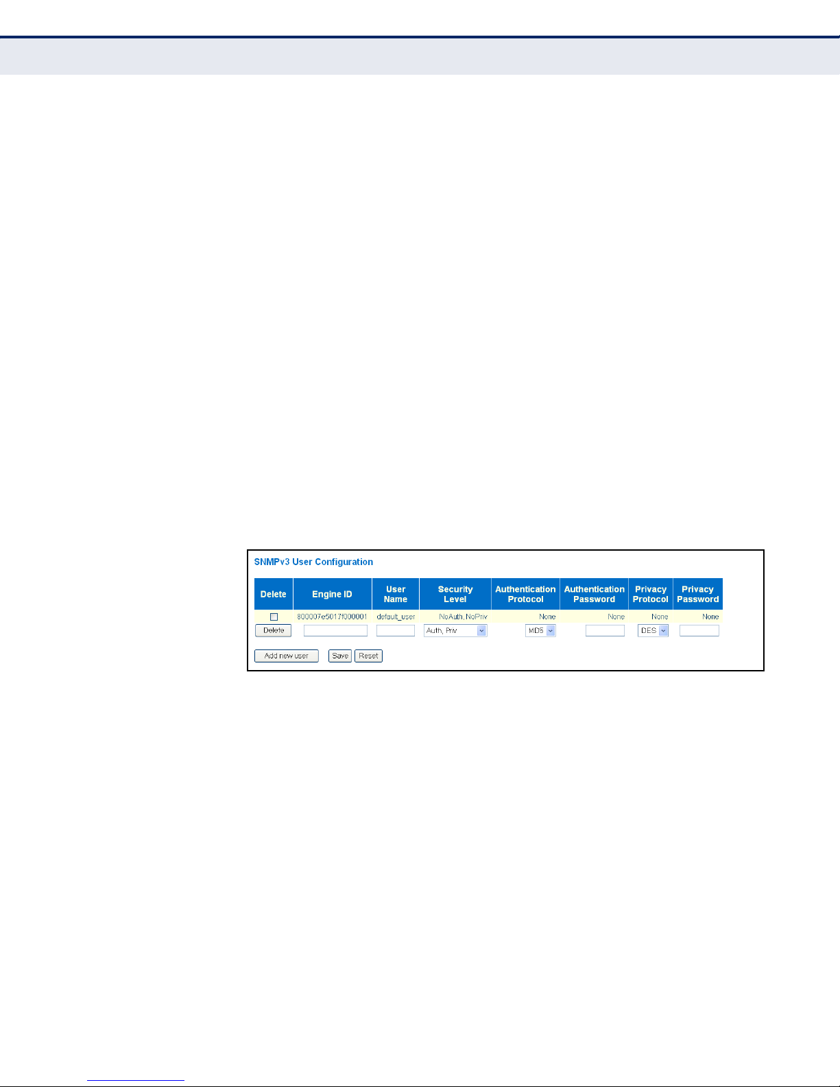
C
HAPTER
Configuring Security
4
| Configuring the Switch
◆ Authentication Password - A plain text string identifying the
authentication pass phrase. (Range: 1-32 characters for MD5, 8-40
characters for SHA)
◆ Privacy Protocol - The encryption algorithm use for data privacy; only
56-bit DES is currently available. (Options: None, DES; Default: DES)
◆ Privacy Password - A string identifying the privacy pass phrase.
(Range: 8-40 characters, ASCII characters 33-126 only)
WEB INTERFACE
To configure SNMPv3 users:
1. Click Configuration, Security, Switch, SNMP, Users.
2. Click “Add new user” to configure a user name.
3. Enter a remote Engine ID of up to 64 hexadecimal characters
4. Define the user name, security level, authentication and privacy
settings.
5. Click Save.
Figure 18: SNMPv3 User Configuration
CONFIGURING SNMPV3 GROUPS
Use the SNMPv3 Group Configuration page to configure SNMPv3 groups.
An SNMPv3 group defines the access policy for assigned users, restricting
them to specific read and write views as defined on the SNMPv3 Access
Configuration page (page 91). You can use the pre-defined default groups,
or create a new group and the views authorized for that group.
CLI REFERENCES
◆ "SNMP Commands" on page 326
PARAMETERS
The following parameters are displayed on the SNMPv3 Groups
Configuration page:
◆ Security Model - The user security model. (Options: SNMP v1, v2c, or
the User-based Security Model – usm).
– 88 –
Page 89

C
HAPTER
4
| Configuring the Switch
Configuring Security
◆ Security Name - The name of user connecting to the SNMP agent.
(Range: 1-32 characters, ASCII characters 33-126 only)
The options displayed for this parameter depend on the selected
Security Model. For SNMP v1 and v2c, the switch displays the names
configured on the SNMPv3 Communities Configuration menu (see
page 86). For USM (or SNMPv3), the switch displays the names
configured with the local engine ID in the SNMPv3 Users Configuration
menu (see page 87). To modify an entry for USM, the current entry
must first be deleted.
◆ Group Name - The name of the SNMP group. (Range: 1-32 characters,
ASCII characters 33-126 only)
WEB INTERFACE
To configure SNMPv3 groups:
1. Click Configuration, Security, Switch, SNMP, Groups.
2. Click “Add new group” to set up a new group.
3. Select a security model.
4. Select the security name. For SNMP v1 and v2c, the security names
displayed are based on the those configured in the SNMPv3
Communities menu. For USM, the security names displayed are based
on the those configured in the SNMPv3 Users Configuration menu.
5. Enter a group name. Note that the views assigned to a group must be
specified on the SNMP Accesses Configuration menu (see page 91).
6. Click Save.
Figure 19: SNMPv3 Group Configuration
– 89 –
Page 90

C
HAPTER
Configuring Security
4
| Configuring the Switch
CONFIGURING SNMPV3 VIEWS
Use the SNMPv3 View Configuration page to define views which restrict
user access to specified portions of the MIB tree. The predefined view
“default_view” includes access to the entire MIB tree.
CLI REFERENCES
◆ "SNMP Commands" on page 326
PARAMETERS
The following parameters are displayed on the SNMPv3 Views
Configuration page:
◆ View Name - The name of the SNMP view. (Range: 1-32 characters,
ASCII characters 33-126 only)
◆ View Type - Indicates if the object identifier of a branch within the MIB
tree is included or excluded from the SNMP view. Generally, if the view
type of an entry is “excluded,” another entry of view type “included”
should exist and its OID subtree should overlap the “excluded” view
entry.
◆ OID Subtree - Object identifiers of branches within the MIB tree. Note
that the first character must be a period (.). Wild cards can be used to
mask a specific portion of the OID string using an asterisk.
(Length: 1-128)
WEB INTERFACE
To configure SNMPv3 views:
1. Click Configuration, Security, Switch, SNMP, Views.
2. Click “Add new view” to set up a new view.
3. Enter the view name, view type, and OID subtree.
4. Click Save.
Figure 20: SNMPv3 View Configuration
– 90 –
Page 91

C
HAPTER
4
| Configuring the Switch
Configuring Security
CONFIGURING SNMPV3 GROUP ACCESS RIGHTS
Use the SNMPv3 Access Configuration page to assign portions of the MIB
tree to which each SNMPv3 group is granted access. You can assign more
than one view to a group to specify access to different portions of the MIB
tree.
CLI REFERENCES
◆ "SNMP Commands" on page 326
PARAMETERS
The following parameters are displayed on the SNMPv3 Access
Configuration page:
◆ Group Name - The name of the SNMP group. (Range: 1-32 characters,
ASCII characters 33-126 only)
◆ Security Model - The user security model. (Options: any, v1, v2c, or
the User-based Security Model – usm; Default: any)
◆ Security Level - The security level assigned to the group:
■
NoAuth, NoPriv - There is no authentication or encryption used in
SNMP communications. (This is the default for SNMPv3.)
■
Auth, NoPriv - SNMP communications use authentication, but the
data is not encrypted.
■
Auth, Priv - SNMP communications use both authentication and
encryption.
◆ Read View Name - The configured view for read access. (Range: 1-32
characters, ASCII characters 33-126 only)
◆ Write View Name - The configured view for write access.
(Range: 1-32 characters, ASCII characters 33-126 only)
WEB INTERFACE
To configure SNMPv3 group access rights:
1. Click Configuration, Security, Switch, SNMP, Access.
2. Click Add New Access to create a new entry.
3. Specify the group name, security settings, read view, and write view.
4. Click Save.
– 91 –
Page 92

C
HAPTER
Configuring Security
4
| Configuring the Switch
Figure 21: SNMPv3 Access Configuration
CONFIGURING PORT
LIMIT CONTROLS
Use the Port Limit Control Configuration page to limit the number of users
accessing a given port. A user is identified by a MAC address and VLAN ID.
If Limit Control is enabled on a port, the maximum number of users on the
port is restricted to the specified limit. If this number is exceeded, the
switch makes the specified response.
CLI REFERENCES
◆ "Port Security Limit Control" on page 349
PARAMETERS
The following parameters are displayed on the Port Limit Control
Configuration page:
System Configuration
◆ Mode – Enables or disables Limit Control is globally on the switch. If
globally disabled, other modules may still use the underlying
functionality, but limit checks and corresponding actions are disabled.
◆ Aging Enabled – If enabled, secured MAC addresses are subject to
aging as discussed under Aging Period.
With aging enabled, a timer is started once the end-host gets secured.
When the timer expires, the switch starts looking for frames from the
end-host, and if such frames are not seen within the next Aging Period,
the end-host is assumed to be disconnected, and the corresponding
resources are freed on the switch.
◆ Aging Period – If Aging Enabled is checked, then the aging period is
controlled with this parameter. If other modules are using the
underlying port security for securing MAC addresses, they may have
other requirements for the aging period. The underlying port security
will use the shortest requested aging period of all modules that use this
functionality. (Range: 10-10,000,000 seconds; Default: 3600 seconds)
Port Configuration
◆ Port – Port identifier. (Range: 1-28)
– 92 –
Page 93

C
HAPTER
4
| Configuring the Switch
Configuring Security
◆ Mode – Controls whether Limit Control is enabled on this port. Both
this and the global Mode must be set to Enabled for Limit Control to be
in effect. Notice that other modules may still use the underlying port
security features without enabling Limit Control on a given port.
◆ Limit – The maximum number of MAC addresses that can be secured
on this port. This number cannot exceed 1024. If the limit is exceeded,
the corresponding action is taken.
The switch is “initialized” with a total number of MAC addresses from
which all ports draw whenever a new MAC address is seen on a Port
Security-enabled port. Since all ports draw from the same pool, it may
happen that a configured maximum cannot be granted if the remaining
ports have already used all available MAC addresses.
◆ Action – If Limit is reached, the switch can take one of the following
actions:
■
None: Do not allow more than the specified Limit of MAC addresses
on the port, but take no further action.
■
Trap: If Limit + 1 MAC addresses is seen on the port, send an SNMP
trap. If Aging is disabled, only one SNMP trap will be sent, but with
Aging enabled, new SNMP traps will be sent every time the limit is
exceeded.
■
Shutdown: If Limit + 1 MAC addresses is seen on the port, shut
down the port. This implies that all secured MAC addresses will be
removed from the port, and no new addresses will be learned. Even
if the link is physically disconnected and reconnected on the port
(by disconnecting the cable), the port will remain shut down. There
are three ways to re-open the port:
■
Boot the switch,
■
Disable and re-enable Limit Control on the port or the switch,
■
Click the Reopen button.
■
Trap & Shutdown: If Limit + 1 MAC addresses is seen on the port,
both the “Trap” and the “Shutdown” actions described above will be
taken.
◆ State – This column shows the current state of the port as seen from
the Limit Control's point of view. The state takes one of four values:
■
■
■
■
Disabled: Limit Control is either globally disabled or disabled on the
port.
Ready: The limit is not yet reached. This can be shown for all
Actions.
Limit Reached: Indicates that the limit is reached on this port. This
state can only be shown if Action is set to None or Trap.
Shutdown: Indicates that the port is shut down by the Limit Control
module. This state can only be shown if Action is set to Shutdown or
Trap & Shutdown.
– 93 –
Page 94

C
HAPTER
Configuring Security
4
| Configuring the Switch
◆ Re-open – If a port is shut down by this module, you may reopen it by
clicking this button, which will only be enabled if this is the case. For
other methods, refer to Shutdown in the Action section.
Note, that clicking the Reopen button causes the page to be refreshed,
so non-committed changes will be lost.
WEB INTERFACE
To configure port limit controls:
1. Click Configuration, Security, Network, Limit Control.
2. Set the system configuration parameters to globally enable or disable
limit controls, and configure address aging as required.
3. Set limit controls for any port, including status, maximum number of
addresses allowed, and the response to a violation.
4. Click Save.
CONFIGURING
AUTHENTICATION
THROUGH NETWORK
ACCESS SERVERS
Figure 22: Port Limit Control Configuration
Network switches can provide open and easy access to network resources
by simply attaching a client PC. Although this automatic configuration and
access is a desirable feature, it also allows unauthorized personnel to easily
intrude and possibly gain access to sensitive network data.
Use the Network Access Server Configuration page to configure IEEE
802.1X port-based and MAC-based authentication settings. The 802.1X
standard defines a port-based access control procedure that prevents
unauthorized access to a network by requiring users to first submit
credentials for authentication. Access to all switch ports in a network can
be centrally controlled from a server, which means that authorized users
– 94 –
Page 95
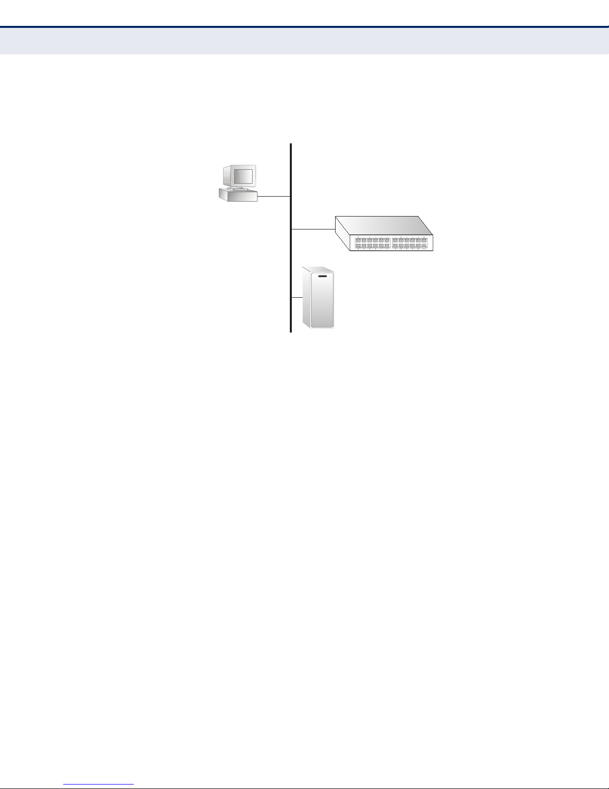
C
802.1x
client
RADIUS
server
1. Client attempts to access a switch port.
2. Switch sends client an identity request.
3. Client sends back identity information.
4. Switch forwards this to authentication server.
5. Authentication server challenges client.
6. Client responds with proper credentials.
7. Authentication server approves access.
8. Switch grants client access to this port.
HAPTER
4
| Configuring the Switch
Configuring Security
can use the same credentials for authentication from any point within the
network.
Figure 23: Using Port Security
This switch uses the Extensible Authentication Protocol over LANs (EAPOL)
to exchange authentication protocol messages with the client, and a
remote RADIUS authentication server to verify user identity and access
rights. These backend servers are configured on the AAA menu (see
page 126).
When a client (i.e., Supplicant) connects to a switch port, the switch (i.e.,
Authenticator) responds with an EAPOL identity request. The client
provides its identity (such as a user name) in an EAPOL response to the
switch, which it forwards to the RADIUS server. The RADIUS server verifies
the client identity and sends an access challenge back to the client. The
EAP packet from the RADIUS server contains not only the challenge, but
the authentication method to be used. The client can reject the
authentication method and request another, depending on the
configuration of the client software and the RADIUS server. The encryption
method used by IEEE 802.1X to pass authentication messages can be MD5
(Message-Digest 5), TLS (Transport Layer Security), PEAP (Protected
Extensible Authentication Protocol), or TTLS (Tunneled Transport Layer
Security). However, note that the only encryption method supported by
MAC-Based authentication is MD5. The client responds to the appropriate
method with its credentials, such as a password or certificate. The RADIUS
server verifies the client credentials and responds with an accept or reject
packet. If authentication is successful, the switch allows the client to
access the network. Otherwise, network access is denied and the port
remains blocked.
The operation of 802.1X on the switch requires the following:
◆ The switch must have an IP address assigned (see page 62).
– 95 –
Page 96

C
HAPTER
Configuring Security
4
| Configuring the Switch
◆ RADIUS authentication must be enabled on the switch and the IP
address of the RADIUS server specified. Backend RADIUS servers are
configured on the Authentication Configuration page (see page 126).
◆ 802.1X / MAC-based authentication must be enabled globally for the
switch.
◆ The Admin State for each switch port that requires client authentication
must be set to 802.1X or MAC-based.
◆ When using 802.1X authentication:
■
Each client that needs to be authenticated must have dot1x client
software installed and properly configured.
■
When using 802.1X authentication, the RADIUS server and 802.1X
client must support EAP. (The switch only supports EAPOL in order
to pass the EAP packets from the server to the client.)
■
The RADIUS server and client also have to support the same EAP
authentication type - MD5, PEAP, TLS, or TTLS. (Native support for
these encryption methods is provided in Windows 7, Windows Vista,
Windows XP, and in Windows 2000 with Service Pack 4. To support
these encryption methods in Windows 95 and 98, you can use the
AEGIS dot1x client or other comparable client software.)
MAC-based authentication allows for authentication of more than one user
on the same port, and does not require the user to have special 802.1X
software installed on his system. The switch uses the client's MAC address
to authenticate against the backend server. However, note that intruders
can create counterfeit MAC addresses, which makes MAC-based
authentication less secure than 802.1X authentication.
CLI REFERENCES
◆ "Network Access Server Commands" on page 354
USAGE GUIDELINES
When 802.1X is enabled, you need to configure the parameters for the
authentication process that runs between the client and the switch (i.e.,
authenticator), as well as the client identity lookup process that runs
between the switch and authentication server. These parameters are
described in this section.
PARAMETERS
The following parameters are displayed on the Network Access Server
Configuration page:
System Configuration
◆ Mode - Indicates if 802.1X and MAC-based authentication are globally
enabled or disabled on the switch. If globally disabled, all ports are
allowed to forward frames.
– 96 –
Page 97

C
HAPTER
4
| Configuring the Switch
Configuring Security
◆ Reauthentication Enabled - Sets clients to be re-authenticated after
an interval specified by the Re-authentication Period. Re-authentication
can be used to detect if a new device is plugged into a switch port.
(Default: Disabled)
For MAC-based ports, reauthentication is only useful if the RADIUS
server configuration has changed. It does not involve communication
between the switch and the client, and therefore does not imply that a
client is still present on a port (see Age Period below).
◆ Reauthentication Period - Sets the time period after which a
connected client must be re-authenticated. (Range: 1-3600 seconds;
Default: 3600 seconds)
◆ EAPOL Timeout - Sets the time the switch waits for a supplicant
response during an authentication session before retransmitting a
Request Identify EAPOL packet. (Range: 1-255 seconds; Default: 30
seconds)
◆ Aging Period - The period used to calculate when to age out a client
allowed access to the switch through Single 802.1X, Multi 802.1X, and
MAC-based authentication as described below. (Range: 10-1000000
seconds; Default: 300 seconds)
When the NAS module uses the Port Security module to secure MAC
addresses, the Port Security module needs to check for activity on the
MAC address in question at regular intervals and free resources if no
activity is seen within the given age period.
If reauthentication is enabled and the port is in a 802.1X-based mode,
this is not so critical, since supplicants that are no longer attached to
the port will get removed upon the next reauthentication, which will
fail. But if reauthentication is not enabled, the only way to free
resources is by aging the entries.
For ports in MAC-based Auth. mode, reauthentication does not cause
direct communication between the switch and the client, so this will not
detect whether the client is still attached or not, and the only way to
free any resources is to age the entry.
◆ Hold Time - The time after an EAP Failure indication or RADIUS
timeout that a client is not allowed access. This setting applies to ports
running Single 802.1X, Multi 802.1X, or MAC-based authentication.
(Range: 10-1000000 seconds; Default: 10 seconds)
If the RADIUS server denies a client access, or a RADIUS server
request times out (according to the timeout specified on the AAA menu
on page 126), the client is put on hold in the Unauthorized state. In this
state, the hold timer does not count down during an on-going
authentication.
In MAC-based Authentication mode, the switch will ignore new frames
coming from the client during the hold time.
◆ RADIUS-Assigned QoS Enabled - RADIUS-assigned QoS provides a
means to centrally control the traffic class to which traffic coming from
a successfully authenticated supplicant is assigned on the switch. The
– 97 –
Page 98

C
HAPTER
Configuring Security
4
| Configuring the Switch
RADIUS server must be configured to transmit special RADIUS
attributes to take advantage of this feature.
The RADIUS-Assigned QoS Enabled checkbox provides a quick way to
globally enable/disable RADIUS-server assigned QoS Class
functionality. When checked, the individual port settings determine
whether RADIUS-assigned QoS Class is enabled for that port. When
unchecked, RADIUS-server assigned QoS Class is disabled for all ports.
When RADIUS-Assigned QoS is both globally enabled and enabled for a
given port, the switch reacts to QoS Class information carried in the
RADIUS Access-Accept packet transmitted by the RADIUS server when
a supplicant is successfully authenticated. If present and valid, traffic
received on the supplicant’s port will be classified to the given QoS
Class. If (re-)authentication fails or the RADIUS Access-Accept packet
no longer carries a QoS Class or it's invalid, or the supplicant is
otherwise no longer present on the port, the port's QoS Class is
immediately reverted to the original QoS Class (which may be changed
by the administrator in the meanwhile without affecting the RADIUSassigned setting).
This option is only available for single-client modes, i.e. port-based
802.1X and Single 802.1X.
RADIUS Attributes Used in Identifying a QoS Class
The User-Priority-Table attribute defined in RFC4675 forms the basis for
identifying the QoS Class in an Access-Accept packet.
Only the first occurrence of the attribute in the packet will be
considered. To be valid, all 8 octets in the attribute's value must be
identical and consist of ASCII characters in the range '0' - '3', which
translates into the desired QoS Class in the range 0-3.
QoS assignments to be applied to a switch port for an authenticated
user may be configured on the RADIUS server as described below:
■
The “Filter-ID” attribute (attribute 11) can be configured on the
RADIUS server to pass the following QoS information:
Table 7: Dynamic QoS Profiles
Profile Attribute Syntax Example
DiffServ service-policy-in=policy-map-name service-policy-in=p1
Rate Limit rate-limit-input=rate rate-limit-input=100
802.1p switchport-priority-default=value switchport-priority-default=2
(in units of Kbps)
■
■
Multiple profiles can be specified in the Filter-ID attribute by using a
semicolon to separate each profile.
For example, the attribute “service-policy-in=pp1;rate-limitinput=100” specifies that the diffserv profile name is “pp1,” and the
ingress rate limit profile value is 100 kbps.
If duplicate profiles are passed in the Filter-ID attribute, then only
the first profile is used.
– 98 –
Page 99

C
HAPTER
4
| Configuring the Switch
Configuring Security
For example, if the attribute is “service-policy-in=p1;service-policyin=p2”, then the switch applies only the DiffServ profile “p1.”
■
Any unsupported profiles in the Filter-ID attribute are ignored.
For example, if the attribute is “map-ip-dscp=2:3;service-policyin=p1,” then the switch ignores the “map-ip-dscp” profile.
■
When authentication is successful, the dynamic QoS information
may not be passed from the RADIUS server due to one of the
following conditions (authentication result remains unchanged):
■
The Filter-ID attribute cannot be found to carry the user profile.
■
The Filter-ID attribute is empty.
■
The Filter-ID attribute format for dynamic QoS assignment is
unrecognizable (can not recognize the whole Filter-ID attribute).
■
Dynamic QoS assignment fails and the authentication result
changes from success to failure when the following conditions
occur:
■
Illegal characters found in a profile value (for example, a nondigital character in an 802.1p profile value).
■
Failure to configure the received profiles on the authenticated
port.
■
When the last user logs off on a port with a dynamic QoS
assignment, the switch restores the original QoS configuration for
the port.
■
When a user attempts to log into the network with a returned
dynamic QoS profile that is different from users already logged on
to the same port, the user is denied access.
■
While a port has an assigned dynamic QoS profile, any manual QoS
configuration changes only take effect after all users have logged
off the port.
◆ RADIUS-Assigned VLAN Enabled - RADIUS-assigned VLAN provides
a means to centrally control the VLAN on which a successfully
authenticated supplicant is placed on the switch. Incoming traffic will
be classified to and switched on the RADIUS-assigned VLAN. The
RADIUS server must be configured to transmit special RADIUS
attributes to take advantage of this feature.
The "RADIUS-Assigned VLAN Enabled” checkbox provides a quick way
to globally enable/disable RADIUS-server assigned VLAN functionality.
When checked, the individual port settings determine whether RADIUSassigned VLAN is enabled for that port. When unchecked, RADIUSserver assigned VLAN is disabled for all ports.
When RADIUS-Assigned VLAN is both globally enabled and enabled for
a given port, the switch reacts to VLAN ID information carried in the
RADIUS Access-Accept packet transmitted by the RADIUS server when
– 99 –
Page 100

C
HAPTER
Configuring Security
4
| Configuring the Switch
a supplicant is successfully authenticated. If present and valid, the
port's Port VLAN ID will be changed to this VLAN ID, the port will be set
to be a member of that VLAN ID, and the port will be forced into VLANunaware mode. Once assigned, all traffic arriving on the port will be
classified and switched on the RADIUS-assigned VLAN ID.
If (re-)authentication fails or the RADIUS Access-Accept packet no
longer carries a VLAN ID or it's invalid, or the supplicant is otherwise no
longer present on the port, the port's VLAN ID is immediately reverted
to the original VLAN ID (which may be changed by the administrator in
the meanwhile without affecting the RADIUS-assigned setting).
This option is only available for single-client modes, i.e. port-based
802.1X and Single 802.1X.
N
OTE
:
For trouble-shooting VLAN assignments, use the Monitor > VLANs >
VLAN Membership and VLAN Port pages. These pages show which modules
have (temporarily) overridden the current Port VLAN configuration.
RADIUS Attributes Used in Identifying a VLAN ID
RFC 2868 and RFC 3580 form the basis for the attributes used in
identifying a VLAN ID in an Access-Accept packet. The following criteria
are used:
■
The Tunnel-Medium-Type, Tunnel-Type, and Tunnel-Private-GroupID attributes must all be present at least once in the Access-Accept
packet.
■
The switch looks for the first set of these attributes that have the
same Tag value and fulfil the following requirements (if Tag == 0 is
used, the Tunnel-Private-Group-ID does not need to include a Tag):
■
Value of Tunnel-Medium-Type must be set to “IEEE-802” (ordinal
6).
■
Value of Tunnel-Type must be set to “VLAN” (ordinal 13).
■
Value of Tunnel-Private-Group-ID must be a string of ASCII
characters in the range 0-9, which is interpreted as a decimal
string representing the VLAN ID. Leading '0's are discarded. The
final value must be in the range 1-4095.
The VLAN list can contain multiple VLAN identifiers in the format
“1u,2t,3u” where “u” indicates an untagged VLAN and “t” a
tagged VLAN.
◆ Guest VLAN Enabled - A Guest VLAN is a special VLAN - typically with
limited network access - on which 802.1X-unaware clients are placed
after a network administrator-defined timeout. The switch follows a set
of rules for entering and leaving the Guest VLAN as listed below.
The “Guest VLAN Enabled” checkbox provides a quick way to globally
enable/disable Guest VLAN functionality. When checked, the individual
port settings determine whether the port can be moved into Guest
– 100 –
 Loading...