

Page 1

TM
DG-GS1526
L2 Gigabit Smart Switch
As our product undergoes continuous development the specifications are subject to change without prior notice
User Manual
V1.0
2010-10-20
Page 2

TM
DG-GS1526 User Manual
COPYRIGHT
Copyright © 2010 by SNSL. All rights reserved. No part of this publication may be reproduced, transmitted, transcribed, stored in a retrieval system, or translated into any language or computer language, in any form or by any means, electronic, mechanical,
magnetic, optical, chemical, manual or otherwise, without the prior written permission of
SNSL.
SNSL makes no representati ons or wa rr anties, either expressed or implied, with respect to
the contents hereof and specifically disclaims any warranties, merchantability or fitness for
any particular purpose. Any software described in this manual is sold or licensed “as is”.
Should the progr ams prov e defecti ve followi ng their pu rchase, the buy er (and not SNSL, its
distributor, or its dealer) assumes the entire cost of all ne cessary servicing, repai r, and any
incidental or consequential damages resulting from any defect in the software. Further,
SNSL reserves the right to revise this publication and to make changes from time to time in
the contents thereof without obligation to notify any person of such re vision or changes.
SNSL an abbreviation of Smartlink Network Systems Ltd.
Page 3

U
SER
M
ANUAL
DG-GS1526 L2 GIGABIT SMART SWITCH
with 24 10/100/1000BASE-T (RJ-45) Ports,
and 2 Gigabit SFP Slots
DG-GS1526
E102010-CS-R01
149100000108A
Page 4

Page 5
ABOUT THIS GUIDE
PURPOSE This guide gives specific information on how to operate and use the
management functions of the switch.
AUDIENCE The guide is intended for use by network administrators who are
responsible for operating and maintaining network equipment;
consequently, it assumes a basic working knowledge of general switch
functions, the Internet Protocol (IP), and Simple Network Management
Protocol (SNMP) .
CONVENTIONS The fol lowing conventions are used throughout this guide to show
information:
N
OTE
:
Emphasizes important information or calls you r attention to related
features or instructions.
C
AUTION
damage the system or equipment.
W
ARNING
:
Alerts you to a potential hazard that could caus e loss of data, or
:
Alerts you to a potential hazard that cou l d cause personal injury.
RELATED PUBLICATIONS The following publication details the hardware features of the switch ,
including the physical and perf ormanc e-relate d characteristics, and how to
install the switch:
The Installation Guide
Also, as part of the switch’s software, there is an online web-based help
that describes all management related fe atures.
REVISION HISTORY This section summarizes the changes in each re vision of this guide.
OCTOBER 2010 REVISION
This is the first version of this guide. This gu ide is v alid for softwar e release
v1.1.1.6.
– 5 –
Page 6

A
BOUT THIS GUIDE
– 6 –
Page 7

CONTENTS
ABOUT THIS GUIDE 5
ONTENTS 7
C
IGURES 11
F
ABLES 13
T
SECTION I GETTING STARTED 15
1INTRODUCTION 17
Key Features 17
Description of Software Features 18
Configuration Backup and Restore 18
Authentication 18
Port Configuration 18
Rate Limiting 18
Port Mirroring 18
Port Trunking 19
Storm Control 19
Static Addr esses 19
IEEE 802.1D Bridge 19
Store-and-Forward Switching 19
Spanning Tree Algorithm 19
Virtual LANs 20
Traffic Prioritization 20
Multicast Filtering 20
System Defaults 21
2INITIAL SWITCH CONFIGURATION 23
Connecti ng to th e S w i tc h 23
Setting an IP Address 23
Setting a Password 25
– 7 –
Page 8

C
ONTENTS
Changing a PC’s IP Address 27
SECTION II WEB CONFIGURATION 29
3USING THE WEB INTERFACE 31
Connecting to the Web Interface 31
Navigating the Web Browser Interface 32
Home Page 32
Configuration Options 32
Panel Display 33
Main Menu 33
4SYSTEM SETTINGS 37
Displaying System Information 37
Setting a User Account 39
Setting an IP Address 40
Setting an IPv4 Address 40
Setting an IPv6 Address 41
5PORT SETTINGS 45
INK AGGREGATION 49
6L
General Link Aggregation Guidelines 49
Creating Trunk Groups 50
Configuring Trunk Settings 52
Configuring LACP 54
7CREATING VLANS 57
IEEE 802.1Q VLANs 57
Assigning Ports to VLANs 58
Configuring VLAN Attributes for Port Members 60
8 VLAN STACKING 61
Configuring IEEE 802.1Q Tunneling 61
VLAN Stacking Table 62
VLAN Stacking Settings 63
9IGMP SNOOPING 65
IGMP Snooping Introduction 65
– 8 –
Page 9

C
ONTENTS
Multicast Entry Table 66
IGMP Snooping Setting 67
IGMP Global Setting 67
IGMP VLAN Setting 69
10 SPANNING TREE 71
Configuring the Spanning Tree Protocol 71
Configuring STP Global Settings 72
Configuring STP Port Settings 75
11 QUALITY OF SERVICE 79
QoS Introduction 79
Port-Based Priority 80
DSCP-Based Priority 81
Priority-to-Queue Mapping 82
Packet Scheduling 84
12 LINK LAYER DISCOVERY PROTOCOL 87
Configuring LLDP 87
LLDP Neighbors 89
13 SNMP SETTINGS 91
Simple Network Management Protocol 91
Setting SNMP System and Community Strings 92
Specifying SNMP Trap Receivers 93
14 PORT MIRRORING 95
ORT SECURITY 97
15 P
ANDWIDTH CONTROL 99
16 B
UMBO FRAME 101
17 J
18 M
ANAGEMENT ACCESS FILTER 103
19 MAC A
MAC Forwarding Table 105
Static MAC Addresses 106
MAC Address Filtering 107
20 802.1X SECURITY 109
Configuring 802.1X Authentication 109
DDRESS SECURITY 105
– 9 –
Page 10

C
ONTENTS
802.1X Global Settings 110
802.1X Port Settings 111
21 GENERAL SECURITY SETTINGS 113
IP Filter Security 113
Storm Control Setting 114
Port Isolation 116
Defence Engine 117
22 PORT STATISTICS 119
23 M
ANAGEMENT TOOLS 121
HTTP Upgrade 121
Restoring Factory Defaults 122
Resetting the Switch 123
SECTION III APPENDICES 125
ASOFTWARE SPECIFICATIONS 127
Software Features 127
Management Features 128
Standards 128
Management Information Bases 129
BTROUBLESHOOTING 131
Problems Accessing the Management Int erface 131
GLOSSARY 133
NDEX 139
I
– 10 –
Page 11

FIGURES
Figure 1: Login Page 24
Figure 2: Web Interface Home Page 24
Figure 3: IP Settings Page 25
Figure 4: User Accounts Page 26
Figure 5: Home Page 32
Figure 6: Front Panel Indicators 33
Figure 7: System Information 38
Figure 8: System Password 39
Figure 9: IPv4 Address Configuration 41
Figure 10: IPv6 Address Configuration 43
Figure 11: Port Configuration 47
Figure 12: Trunk Group Setting 51
Figure 13: Trunk Distribution Algorithm Setting 53
Figure 14: LACP Port Configuration 55
Figure 15: VLAN Membership Configuration 59
Figure 16: VLAN Port Configuration 60
Figure 17: VLAN Stacking Table 63
Figure 18: VLAN Stacking Settings 64
Figure 19: Multicast Entry Table 66
Figure 20: IGMP Snooping Global Settings 68
Figure 21: IGMP Snooping VLAN Settings 69
Figure 22: STP Global Setting 74
Figure 23: STP Port Setting 78
Figure 24: Port-Based Priority Setting 81
Figure 25: DSCP-Based Priority Setting 82
Figure 26: Priority-to-Queue Mapping 83
Figure 27: Packet Scheduling 85
Figure 28: LLDP Settings 88
Figure 29: LLDP Neighbors 90
Figure 30: SNMP Settings 93
Figure 31: SNMP Trap Receiver Settings 94
– 11 –
Page 12

F
IGURES
Figure 32: Port Mirroring 96
Figure 33: Port Security 98
Figure 34: Bandwidth Control 100
Figure 35: Jumbo Frame Setting 101
Figure 36: Management Access Filter 104
Figure 37: MAC Address Forwarding Table 106
Figure 38: Static MAC Setting 107
Figure 39: MAC Address Filtering 108
Figure 40: 802.1X Setting 111
Figure 41: 802.1X Port Setting 112
Figure 42: IP Filter Setting 114
Figure 43: Storm Control Settings 115
Figure 44: Port Isolation Settings 116
Figure 45: Defence Engine Setting 117
Figure 46: Port Statistics 120
Figure 47: Software Upgrade 122
Figure 48: Restoring Factory Defaults 122
Figure 49: Reboot Switch 123
– 12 –
Page 13

TABLES
Table 1: Key Features 17
Table 2: System Defaults 21
Table 3: Web Page Configuration Buttons 32
Table 4: Main Menu 33
Table 5: Recommended STP Path Cost Range 75
Table 6: Reco mmended STP Pat h Costs 75
Table 7: Default STP Path Costs 76
Table 8: Default Mapping of CoS Values to Egress Queues 82
Table 9: CoS Priority Levels 83
Table 10: LLDP System Capabilities 89
Table 11: Troubleshooting Chart 131
– 13 –
Page 14

T
ABLES
– 14 –
Page 15

S
ECTION
GETTING STARTED
This section provides an overview of the switch, and introduces some basic
concepts about network switches. It also describes the basic settings
required to access the management interface.
This section includ es these chapters:
◆ "Introduction" on page 17
◆ "Initial Switch Configuration" on page 23
I
– 15 –
Page 16

S
ECTION
| Getting Started
– 16 –
Page 17

1 INTRODUCTION
This switch provides a broad range of features for Layer 2 switching. It
includes a management agent that allows you to configure the fe atures
listed in this manual. T he def aul t c onfigu r ation ca n be us ed for most o f the
features provided by this switch. Howev er, there are many options that you
should configure to maximize the switch’s performance for your particular
network envi ronment.
KEY FEATURES
Table 1: Key Features
Feature Description
Configuration Backup
and Restore
Backup to management station or TFTP server
Authentication Web – user name/password, RADIUS
DHCP Client Supported
Port Configuration Speed, duplex mo de , fl ow control
Rate Limiting Input rate limiting per port
Port Mirroring One or more port s m irr or ed to single analy sis port
Port T r unking Supports up to 8 trunks using either static or dynamic trunking
Storm Control Throttling for broadcast, multicast, and unknown unicast storms
Address Table Up to 16K MAC addresses in the forwarding table, 1024 static MAC
IP Version 4 and 6 Supports IPv4 and IPv6 addressing
IEEE 802.1D Bridge Supports dynamic data switching and addresses learning
Store-and-Forward
Switching
Spanning Tree Algorithm Supports Rapid Spann in g Tree Protocol (RSTP) , whic h in c lud e s
Virtual LANs Up to 256 using IEEE 802.1Q, port-based, and QinQ VLAN
Traffic Prioritization Queue mode and Co S co n fi gur e d by port or DSCP
SNMP v1/2c - Community strings
Port – IEEE 802.1X, MAC address filtering
DHCP Snooping (with Option 82 relay information)
IP Filter
(LACP)
addresses
Supported to ensure wire-speed switching while eliminating bad
frames
STP backward compatible mode
Stacking
Multicast Filtering Supports IGMP sn ooping and query
– 17 –
Page 18

C
HAPTER
Description of Software Features
1
| Introduction
DESCRIPTION OF SOFTWARE FEATURES
The switch provides a wide range of advanced performance enhancing
features. Flow control eliminates the los s of packets due to bottlenecks
caused by port saturation. Storm suppression prevents broadcast,
multicast, and unknown unicast tr affic storms from engulfing the network.
Untagged (port-based) and tagged VLANs provide traffic security and
efficient use of network bandwidth. CoS priority queueing ensures the
minimum delay for moving real-time multimedia data across the network.
While multicast filtering provides support for real-time network
applications.
Some of the management features are brief l y described below.
CONFIGURATION
BACKUP AND
RESTORE
You can save the current co nfiguration settings to a file on the
management station (using the web interface) and later download this file
to restore the switch configuration settings.
AUTHENTICATION This switch authenticates management access via a web browser. User
names and passwords can be configured locally Port-based authentication
is also supported via the IEEE 802.1X protocol. This protocol uses
Extensible Authentication Protocol over LANs (EAPOL) to request user
credentials from the 802.1X client, and then uses the EAP between the
switch and the authentication server to verify the client’s right to access
the network via an authentication server (i.e., RADIUS server).
PORT CONFIGURATION Yo u can manually configure the speed and dup l ex mode, and flow control
used on specific ports, or use auto-negotiation to detect the connection
settings used by the attached device. Use the full-du plex mode on ports
whenever possible to double the throughput of switch connections. Flow
control should also be enabled to control network traffic during periods of
congestion and prev ent th e los s of packet s when p ort bu ffer thresholds are
exceeded. The switch supports flow control based on the IEEE 802.3x
standard (now incorporated in IEEE 802.3-2005).
RATE LIMITING This feature controls the maxim u m rate for traffic tran smitted or received
on an interface. Rate limiting is configu red on interfaces at the edge of a
network to limit traffic into or out of the network. Traffic that falls within
the rate limit is trans mitted, while packets that exceed the acceptable
amount of traffic are dropped.
PORT MIRRORING The switch can unobtru sively mirror tr affic from any po rt to a monitor port.
You can then attach a protocol analyzer or RMON probe to this port to
perform traffic analysis and verify connection integrity.
– 18 –
Page 19

C
HAPTER
Description of Software Features
1
| Introduction
PORT TRUNKING Ports can be combined into an aggregate connection. Trunks can be
manually set up or dynamically configured using Link Aggregation Control
Protocol (LACP – IEEE 802.3-2005). The additional ports dramatically
increase the throughput across any connection, and prov ide redundancy by
taking over the load if a port in the trunk should fail. The s witch supports
up to 8 trunks.
STORM CONTROL Broadcast, multicast and unknown unicast storm suppression prevents
traffic from overwhelming the network.When enabled on a port, the level of
broadcast traffic passing through the port is restricted. If broadcast traffic
rises above a pre-defined thres hold, it will be throttled until the level falls
back beneath the threshold.
STATIC ADDRESSES A static address can be assigned to a specific interface on this switch.
Static addresses are bound to the assigned interface and wi ll not be
moved. When a static address is seen on another interface, the address will
be ignored and will not be written to the address table. Static addresses
can be used to provide network security by restricting access for a known
host to a specific port.
IEEE 802.1D BRIDGE The switch supports IEEE 802.1D transparent bridging. The address table
facilitates data switching by learning addresses, and then filte ring or
forwarding traffic bas ed on this informati on. The addre ss table suppo rts up
to 16K addresses.
STORE-AND-FORWARD
SWITCHING
SPANNING TREE
The switch copies each frame into its memory before forwarding them to
another port. This ensures that all frames are a standard Ether net size and
have been verified for accuracy with the cyclic redundancy check (CRC).
This prevents bad frames from enter ing the network and wasting
bandwidth.
To avoid dropping frames on congested ports, the switch provides 448 KB
for frame buffering. Thi s buf fer can queue packets awaiting transmission
on congested networks.
The switch supports these spanning tree protocols:
ALGORITHM
◆ Spanning Tree Protocol (STP, IEEE 802.1D) – Supported by using the
STP backward compatible mode provided by RSTP. STP provides loop
detection. When there are multiple physical paths between segments,
this protocol will choose a single path and disable all others to ensure
that only one route exists between any two stations on the networ k.
This prevents the creation of network loops. However, if the chosen
path should fail for any reason, an alternate path will be activated to
maintain the connection.
– 19 –
Page 20

C
HAPTER
Description of Software Features
1
| Introduction
◆ Rapid Spanning Tree Protocol (RSTP, IEEE 802.1w) – This protocol
VIRTUAL LANS The switch supports up to 256 VLANs. A Virtual LAN is a collection of
network nodes that share the same collision domain regardless of their
physical location or connection point in the network. The switch supports
tagged VLANs based on the IEEE 802.1Q standard. Members of VLAN
groups can be manually assigned to a specifi c set of VLANs. This allows the
switch to restrict traffic to the VLAN groups to which a user has been
assigned. By segmenting your network into VLANs, y ou can:
◆ Eliminate broadcast storms which severely degrade performance in a
reduces the conver gence time for ne twork topo logy changes to about 3
to 5 seconds, compare d to 30 se co nd s or mor e fo r the olde r IEE E
802.1D STP standard. It is intended as a complete replacement for STP,
but can still interoperate with switches running the older standard by
automatically reconfiguring ports to STP-compliant mode if they detect
STP protocol messages f rom attached devices.
flat network.
◆ Simplify network management for node changes/moves by remotely
configuring VLAN membership for any port, rather than having to
manually change the network conn ection.
◆ Provide data security by restricting all traffic to the originating VLAN.
TRAFFIC
PRIORITIZATION
This switch prioritizes each packet based on the require d level of service,
using eight priority queues with strict, W e ighted Fair Queuing, or W eig hted
Round Robin Qu euing. It uses IEEE 802.1p and 802.1Q tags to prioritize
incoming traffic based on input from the end-s tation application. These
functions can
data and best-effort data.
This switch also supports several common methods of prioritizing layer 3/4
traffic to meet app lication re quiremen ts . Traffic can be prioriti ze d based on
the priority bits i n the IP fr ame’s Type of Service (ToS) octet or the number
of the TCP/UDP port. When these services are enabled, the priorities are
mapped to a Class of Service value by the switch, and the traf fic th en sent
to the corresponding output queue.
be used to provide independent priorities for delay-sensitive
MULTICAST FILTERING Specific multicast traffic can be assigned to its own VLAN to ensure that it
does not interfere with normal networ k traffic and to guarantee real-time
delivery by setting the required priority level for the designated VLAN. The
switch uses IGMP Snooping and Query to manage multicast group
registration.
– 20 –
Page 21

SYSTEM DEFAULTS
C
HAPTER
The following table lists some of the basic system defaults.
Table 2: System Defaults
Function Parameter Default
Authentication User Name admin
Password admin
802.1X Port Authentication Disabled
Port Security Disabled
IP Filtering Di sab le d
Web Management HTTP Server Enabled
HTTP Port Number 80
SNMP SNMP Agent Disabled
1
| Introduction
System Defaults
Community Strin gs “public” (read only)
Port Configuration Admin Status Enabled
Auto-negotiation Enabled
Flow Control Disabled
Rate Limiting Input and output limits Disabled
Port Trunking Static Trunks None
LACP (all ports) Disabled
Storm Protection Status Broadcast: disabled
Spanning Tree Algorithm Status Enabled, RSTP
Edge Port Enabled
Virtual LANs Default VLAN 1
PVID 1
Traffic Prioritization Ingress Port Priority 0
Queue Mode We ighted Fai r Queuing
Weighted Fair Queuing Queue: 1 2 3 4 5 6 7 8
“private” (read/write)
Multicast: disabled
Unknown unicast: disabled
(Defaults: RSTP standard)
Weight: 1 2 3 4 5 6 7 8
IP Settings IP Address 192.168.1.1
Multicast Filtering IGMP Snooping Snooping: Disabled
IP DSCP Priority Disabled
Subnet Mask 255.255.255.0
Default Gateway 0.0.0.0
DHCP Client: Disabled
Querier: Disabled
– 21 –
Page 22

C
HAPTER
1
| Introduction
System Defaults
– 22 –
Page 23

2 INITIAL SWITCH CONFIGURATION
This chapter includes information on connecting to the switch and basic
configuratio n procedures .
The switch inclu d es a bu il t-in network management agent. The ag e n t
offers a web-based management interface, and it also supports
management through SNMP (Simple Network Management Protoc ol).
The switch’s web management interfac e allo ws you to conf igu r e swit ch
parameters, monitor port conne ctions, and display statistics using a
standard web browser such as Internet Explorer 5.x or above, Netscape
6.2 or above, and Mozilla Firefox 2.0 or above. The web management
interface can be accessed from any computer attached to the network.
CONNECTING TO THE SWITCH
SETTING AN IP
DDRESS
A
To make use of the management features of your switch, you must first
configure it with an IP address that is compatible with the network it is
being installed in. This should be done before you permanently install the
switch in the network.
N
OTE
:
By default, the IPv4 address for this switch is set to 192.168.1.1
with subnet mask 255.255.255.0.
Follow this procedure:
1. Place your switch close to the PC that you intend to us e for
configuration. It helps if you can see the front pane l of the switch while
working on your PC.
2. Connect the Ethernet port of your PC to any port on the front panel of
your switch. C o nnect p o w er to the switch a nd verify that you h a ve a
link by checking the front-panel LE Ds.
3. Check that your PC has an IP address on the same subnet as the
switch. The default IP address of the switch is 192.168.1.1 and the
subnet mask is 255.255.255.0, so the PC and switch are on the same
subnet if they both have addresses that start 192.168.1.x. If the PC
and switch are not o n the same su bnet, y ou must manual ly set the PC ’ s
IP address to 192.168.1.x (where “x” is any number from 2 to 255). If
– 23 –
Page 24
C
HAPTER
Connecting to the Switch
2
| Initial Switch Configuration
you are unfamiliar with this process, see “Changing a PC’s IP Address”
on page 27.
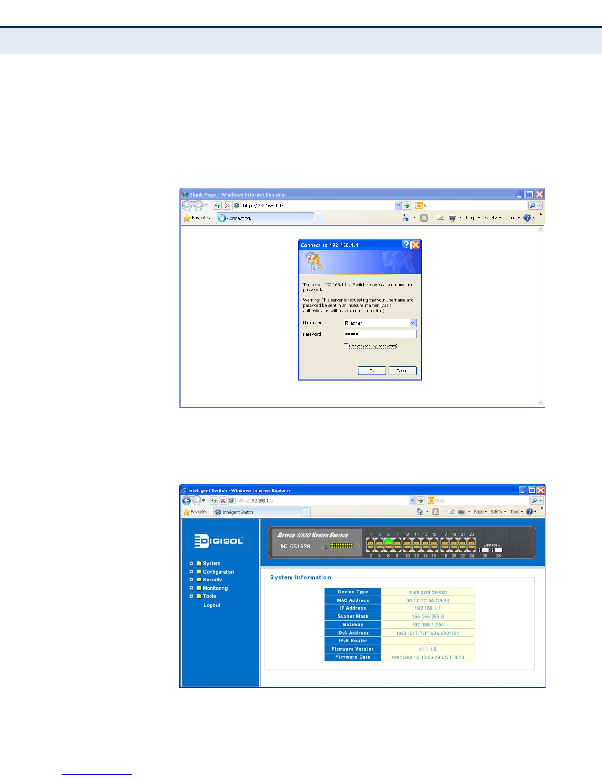
4. Open your web browser and enter the address http://192.168.1.1. If
your PC is properly configured, you will see the login page of your
switch. If you do not see the login page, repeat step 3.
Figure 1: Login Page
5. Enter the default user name “admin” and password “admin,” then click
the OK button to access the web interf ace home page.
Figure 2: Web Interface Home Page
– 24 –
Page 25

C
HAPTER
2
| Initial Switch Configuration
Connecting t o the Switch
6. From the menu, click on System, then IP Settings. On the IP Address
Setting page, enter the new IP address, Subnet Mask and Gateway IP
Address for the switch, then click on the Apply button.
N
OTE
:
The switch also s upp o rts dyn am ic IP v4 addr es s as signment through
DHCP (Dynamic Host Configuration Protocol). The switch sends IPv4
configuration requests to DHCP servers on the network.
N
OTE
:
The switch also supports IPv6 addressing. By default the switch
automatically generates a unique IPv6 host address based on the local
subnet address prefix received in router advertisement messages. Fo r
more information, see “Setting an IPv6 Address” on page 41.
Figure 3: IP Settings Page
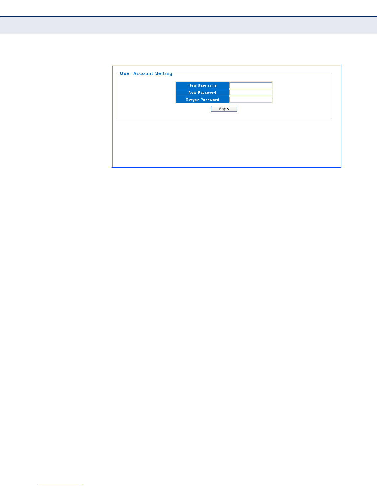
SETTING A PASSWORD No other configuration changes are required at this stage, but before
logging out it is recommended that you change the default administrator’s
user name and password for access to the switch, record them, and put
them in a safe place.
User names can consist of up to 16 alphanumeric characters, and
passwords can be up to 8 characters . Bo th user names and passwords are
case sensitive.
To prevent unauthorized access to the switch, set a password as follows:
1. On the menu, click System and then User Account.
– 25 –
Page 26
C
HAPTER
Connecting to the Switch
2
| Initial Switch Configuration
Figure 4: User Accounts Page
2. In the New Username field, define an administrator user name.
3. In the New Password field, define an administrator password.
4. Confirm the new password setting in the Retype Password field.
5. Click the Apply button.
– 26 –
Page 27

CHANGING A PC’S IP ADDRESS
To change the IP address of a Windows 2000 PC:
1. Click Start, Settings, then Network and Dial-up Connections.
2. For the IP address you want to change, right-click the network
connection icon, and then click Properties.
3. In the list of components used by this connection on Ge neral tab, sele ct
Internet Protocol (TCP/IP), and then click the Properties button.
4. In the Internet Protocol (TCP/IP) Propertie s dialo g box, click to select
Use the following IP address. Then type your intended IP address,
Subnet mask, and Default gateway in the prov ided text boxes.
5. Click OK to save the changes.
C
HAPTER
2
| Initial Switch Configuration
Changing a PC’s IP Address
To change the IP address of a Windows XP PC:
1. Click Start, Control Panel, then Network Connections.
2. For the IP address you want to change, right-click the network
connection icon, and then click Properties.
3. In the list of components used by this connection on Ge neral tab, sele ct
Internet Protocol (TCP/IP), and then click the Properties button.
4. In the Internet Protocol (TCP/IP) Propertie s dialo g box, click to select
Use the following IP address. Then type your intended IP address,
Subnet mask, and Default gateway in the prov ided text boxes
5. Click OK to save the changes.
N
OTE
:
For users o f systems ot her th an Windows 2000 or Windows XP, refer
to your system documentation for info rmation on changing the PC’s IP
address.
– 27 –
Page 28

C
HAPTER
2
| Initial Switch Configuration
Changing a PC’s IP Address
– 28 –
Page 29

S
ECTION
WEB CONFIGURATION
This section describes the basic switch features , along with a detailed
description of how to conf igure each feature via a web browser.
This section includ es these chapters:
◆ "Using the Web Interface" on page 31
◆ "System Settings" on page 37
◆ "Port Settings" on page 45
◆ "Link Aggregation" on page 49
II
◆ "Creating VLANs" on page 57
◆ "VLAN Stacking" on page 61
◆ "IGMP Snooping" on page 65
◆ "Spanning Tree" on page 71
◆ "Quality of Service" on page 79
◆ "Link Layer Discover y Pro toc ol" on page 87
◆ "SNMP Settings" on page 91
◆ "Port Mirroring" on page 95
◆ "Port Security" on page 97
◆ "Bandwidth Control" on page 99
◆ "Jumbo Frame" on page 101
◆ "Management Access Filter" on page 103
◆ "MAC Address Security" on page 105
◆ "802.1X Security" on page 109
– 29 –
Page 30

S
ECTION
| Web Configuration
◆ "General Security Settings" on page 113
◆ "Port Statistics" on page 119
◆ "Management Tools" on page 121
– 30 –
Page 31

3 USING THE WEB INTERFACE
The switch provides an embedded HTTP web agent. Using a web browser
you can configure the sw itch and view statistics to monitor network
activity. The web agent can be accessed by any computer on the network
using a standard web browser (Internet Explorer 5.0, Netscape 6.2, Mozilla
Firefox 2.0, or more recent versions).
CONNECTING TO THE WEB INTERFACE
Prior to accessing the switch from a web browser, be sure you have first
performed the following tasks:
1. Configured the switch with a va lid IP address, subnet mask, and default
gateway using the web interface, or DHCP protocol. By default, the
IPv4 address is set to 192.168.1.1. (See “Setting an IP Address” on
page 40.)
2. Set the system password usi ng th e web i nterf ace. (Se e “Set ting a User
Account” on page 39.)
3. After you enter a user name and password, you will have access to the
system configuration pro gram.
N
OTE
:
You are allowed three attempts to enter the correct password; on
the third failed attempt the current connection is terminated.
N
OTE
:
If the path between your management station and this switch does
not pass through any device that uses the Spanning Tree Protocol, then
you can set the switch port attached to your management station to fast
forwarding (enable as an Edge po rt ) to i mpro v e t he swit ch’s response time
to management commands issued through the web in terface. See
“Configuring STP Port Settings” on page 75.
– 31 –
Page 32

C
HAPTER
Navigating th e Web B rowser Interface
3
| Using the Web Interface
NAVIGATING THE WEB BROWSER INTERFACE
To access the web-browser interface you mus t first enter a user name and
password. By default, the user name is “admin” and password “admin.”
HOME PAGE When your web browser connects with the switch’s web agent, the home
page is displayed as shown below. The home page displays the Main Menu
on the left side of the screen and an image of the front panel on the right
side. The Main Menu links are used to navig ate to other menus, an d display
configuration parameters and statistics.
Figure 5: Home Page
CONFIGURATION
OPTIONS
Configurable parameters have a dialog box or a drop-down list. Once a
configuration change has been made on a page, be sure to click on the
Apply button to confirm the new setting. The following table summarizes
common web page configurati on buttons.
Table 3: Web Page Configuration Buttons
Button Action
Apply Sets specified values to the system.
Add Adds an entry to a feature table.
Delete Removes an entry from a feature table.
– 32 –
Page 33

C
HAPTER
3
| Using the Web Interface
Navigating the Web Browser Interface
N
OTE
:
To ensure proper screen refresh, be sure that Internet Explorer is
configured so that the setting “Check for newer versions of stored pages”
reads “Every visit to the page.”
Internet Explorer 6.x and earlier: This option is available under the menu
“Tools / Internet Options / General / Temporary Internet Files / Settings.”
Internet Explorer 7.x: This option is available unde r “Tools / Internet
Options / General / Browsing Histor y / Settings / Temporary Internet Files.”
PANEL DISPLAY The web agent displays an image of the switch’s ports. The data displayed
on the screen is automatically refreshed approximately once eve ry 10
seconds.
Figure 6: Front Panel Indicators
MAIN MENU Using the onboard web agent, you can define system parameter s, manage
and control the switch, and all its ports, or monitor network conditions. Th e
following table briefly describes the selections available from this program.
Table 4: Main Menu
Menu Description Page
System
Information Configures system contact, name and location 37
IP Setting Configures IPv4 settings 40
IPv6 Setting Configures IPv6 settings 41
User Account Configures system password 39
Port Settings Configures port connection settings 45
Configuration
Link Aggregation
Trunk Group Setting Specifies port s to group into static trunks 50
Trunk Setting Configures the tr unk bal a nc ing algor ithm 52
LACP Setting Allow s po rts to dy nam ic a lly join trunk s 54
VLAN
Static VLAN Configures VLAN groups 58
VLAN Setting Specifies default PVID for ports 60
– 33 –
Page 34

C
HAPTER
3
| Using the Web Interface
Navigating th e Web B rowser Interface
Table 4: Main Menu
Menu Description Page
VLAN Stacking
S-VLAN Table Sets QinQ settings for the switch 62
S-VLAN Setting Sets QinQ settings for ports 63
IGMP Snooping
Multicast Entry Table Displays multicas t gr oup s to be filte re d fo r VLA N s 66
IGMP Snooping Setting Configures global and port settings for multicast filtering 67
Spanning Tree
STP Global Setting Configures global bridge settings for RSTP 72
STP Port Setting Con figures individual port settings for RST P 75
QoS
Port-based Priority Configures the de f a ult Co S traffi c cl ass fo r por ts 80
DSCP-based Priority Maps DSCP values to stan dard CoS classes 81
Priority to Queue
Mapping
Packet Scheduling Configures port queue mo de and queue weights 84
LLDP
LLDP-Setting Configures global and por t LLDP settings 87
LLDP Neighbors Displays LLDP information about a remote device
SNMP Configures read-only and read/write community strings
Port Mirroring Sets source and target ports for mirroring 95
Port Security Configures source MAC addre s s lim its for ports 97
Bandwidth Control Configur es ingress and egress rate limits 99
Jumbo Frame Enables Jumbo Frame sup port 101
Management Access Filt er Sets IP addresses of clien ts allowed man agement access 103
Security
MAC Address
MAC Forwarding Table Displays dynamic and static addresses 105
Static MAC Configures static MAC addresses 106
MAC Filtering Sets source and destination MAC address filters 10 7
Configures CoS tr affic class to port queue mapp ing 82
89
connected to ports on th is switch
91
for SNMP v1/v2c, engine ID for SNMP v3, and trap
parameters
802.1x
802.1x Setting Configures global 802.1X settings 110
802.1x Port Setting Configures 802.1X settings for ports 111
IP Filter Setting Filters traffic bas e d IP addr e ss e s 113
Storm Control Sets limits for broadcast, multicast , and unknown
unicast traffic
114
– 34 –
Page 35

C
HAPTER
3
| Using the Web Interface
Navigating the Web Browser Interface
Table 4: Main Menu
Menu Description Page
Port Isolation Limits traffic to and from specified ports 116
Defence Engine Provides prote ct ion from traffic storms 117
Monitoring
Port Statistics Shows detailed Ethe rnet port statistics 119
Tools
HTTP Upgrade Updates software on the switch, and saves/restores
Reset Restarts the switch and resto res factory default setting s 122
Reboot Restarts the switch 123
configuration settings from a file on the management
station
121
– 35 –
Page 36

C
HAPTER
3
| Using the Web Interface
Navigating th e Web B rowser Interface
– 36 –
Page 37

4 SYSTEM SETTINGS
This chapter describes some basic system settings on the switch. It
includes the following sections:
◆ “Displaying System Information” on page 37
◆ “Setting a User Account” on page 39
◆ “Setting an IP Address” on page 40
DISPLAYING SYSTEM INFORMATION
The System>Information page displays some basic settin gs for the switch,
including MAC address, IPv4 and IPv6 settings, and software version
information.
PARAMETERS
These parameters are displayed on the System Information page:
◆ Device Type – Descr i bes the switch system type.
◆ MAC Address – The physical layer address for this switch.
◆ IP Address – The current IPv4 addr e ss of the swi tch .
◆ Subnet Mask – The current IPv4 subnet mask of the switch.
◆ Gateway – IPv4 address of the gateway router be tween the switch and
management stations that exist on other network segments.
◆ IPv6 Address – The current IPv6 address of the sw itch.
◆ IPv6 Router – The IPv6 address of the default next hop router.
◆ Firmware Version – Version numbe r of th e sw i tc h so ft wa r e.
◆ Firmware Date – Release date of the switc h so ftware.
– 37 –
Page 38

C
HAPTER
Displaying System Information
4
| System Settings
WEB INTERFACE
To view System Information in the web interface, click System, then
Information.
Figure 7: System Information
– 38 –
Page 39

SETTING A USER ACCOUNT
The administrator has read/write access for all parameters governing the
onboard agent. Y ou should therefore assign a new administr ator user name
and password as soon as possible, and store them in a safe place.
The default administrator user name is “admin” and password is “admin.”
User names can consist of up to 16 alphanumeric characters, and
passwords can be up to 8 characters . Bo th user names and passwords are
case sensitive.
WEB INTERFACE
To configure the System Password in the web interface:
1. Click System, then User Account.
2. Enter the new user name.
C
HAPTER
4
| System Sett ings
Setting a User Account
3. Enter the new password.
4. Enter the new password again to confirm your input.
5. Click Save.
Figure 8: System Password
– 39 –
Page 40

C
HAPTER
Setting an IP Address
4
| System Settings
SETTING AN IP ADDRESS
This section describes ho w to configure an IP interface for management
access to the switch o ver the network. This switch support s both IP Version
4 and Version 6, and can be managed simultaneously through either of
these address types. You can manually configure a specific IPv4 or IPv6
address, or direct the switch to obta in an IPv4 address from a DHCP server
when it is powered on. An IPv6 address can either be manually configured
or automatically generated.
SETTING AN IPV4
ADDRESS
The IPv4 address for the switch is set to 192.168.1.1 by default. Y ou may
need to manually configure the switch’s default settings to values that are
compatible with your network. You may also need to a establish a default
gateway between the switch and management stations that exist on
another network segment.
You can manually configure a specific IPv4 address, or direct the device to
obtain an address from a DHCP server. Valid IP addresses consist of four
decimal numbers, 0 to 255, separ ated by perio ds. Anythi ng other than this
format will not be accepted by the CLI program.
PARAMETERS
The following parameters are displayed on the IP Address Setting page:
◆ Mode – Specifies whether IP settings are assigned manually or through
the Dynamic Host Configuration Protocol (DHCP). (Default: Static IP)
■
Static IP – The IPv4 settings are set manually by the user.
■
DHCP – When enabled, IP will not function until a reply has been
received from the server. Requests will be bro adcast per iodically by
the switch for an IP address. DHCP values can include the IP
address, subnet mask, and default gateway.
N
OTE
have no configured IPv 4 address.
◆ IP Address – The IPv4 address for the switch. Valid IP addresses
consist of four numbers, 0 to 255, separa ted by periods. (Default:
192.168.1.1)
◆ IP Mask – This mask identifies the host address bits used for routing
to specific subnets. (Default: 255.255.255.0)
◆ IP Router – IP address of the gateway router between the switch and
management stations that exist on other network segments.
:
If the switch does not receive a response from a DHCP server, it will
– 40 –
Page 41

C
HAPTER
4
| System Sett ings
Setting an IP Address
WEB INTERFACE
To con figu re stati c IPv4 addre ss se t ting s:
1. Click System, then IP Setting.
2. Set the Mode to “Static IP.”
3. Specify the IPv4 address, subnet mask, and gateway address.
4. Click Apply.
Figure 9: IPv4 Address Configuration
SETTING AN IPV6
ADDRESS
This section describes how to configure an IPv6 interface for management
access over the network.
IPv6 includes two distinct address types; link-local unicast and global
unicast. A link-local address makes the switch accessible over IPv6 for all
devices attached to the same local subnet. Management traffic using this
kind of address cannot be passed by any router outside of the subnet. A
link-loc al addre ss is easy to set up , and may be usef ul for simple networks
or basic troubleshooting tasks. However, to connect to a larger network
with multiple segments, the switch must be configured with a global
unicast address. A link-local address must be manually configured, but a
global unicast address can either be manually configured or dynamically
assigned.
USAGE GUIDELINES
◆ All IPv6 addresses must be formatted according to RFC 2373 “IPv6
Addressing Architecture,” using 8 colon-separated 16-bit hexadecimal
values. One double colon may be us ed in the address to indicate the
appropriate number of zeros required to fill the undefined fields.
◆ When configuring a link-local address, note that the prefix length is
fixed at 64 bits, and th e ho st po rtio n of the def aul t addr ess i s base d on
the modified EUI-64 (Extended Universal Identifier) form of the
interface identifier (i.e., the physical MAC address). You can manually
– 41 –
Page 42

C
HAPTER
Setting an IP Address
4
| System Settings
configure a link-local address by entering the full address with the
network prefix FE80.
◆ To connect to a large r ne t w ork with multiple subn e t s , you must
configure a global unicast address. There are several alternatives to
configuring this address type:
■
The global unicast address can be automatically configured by
taking the network prefix from router advertiseme nts observed on
the local interface, and using the modified EUI-64 form of the
interface identifier to automatically create the host portion of the
address. This option can be selected by enabling the Auto
Configuration opti on.
■
You can also manually configure the global unicast address by
entering the full address and prefix length.
PARAMETERS
The following parameters are displayed on the IPv6 Address Setting page:
◆ Auto Configuration – Enables stateless autoconfiguration of IPv6
addresses on an interface and enables IPv6 functionality on the
interface. The network portion of the address is based on prefixes
received in IPv6 router advertisement messages, and the host portion
is automatically generate d usin g the modified EUI-64 form of the
interface identifier; i.e., the switch's MAC address. (Default: Disabled)
◆ IPv6 Address – Manually configures a global unicast address by
specifying the full address and network prefix length (in the Prefix
field). (Default: null)
◆ Prefix Length – Defines the pr efix length as a de cimal val ue indicatin g
how many contiguous bits (star ting at the le ft) of the address compris e
the prefix; that is, the network portion of the addr ess . (Default: 0)
◆ Router – Sets the IPv6 address of the default next hop router.
An IPv6 default gateway must be defined if the management stat ion is
located in a different IPv6 segment.
An IPv6 default gateway can only be successfully set when a network
interface that directly connects to the gateway has been configured on
the switch.
– 42 –
Page 43

C
HAPTER
4
| System Sett ings
Setting an IP Address
WEB INTERFACE
To configure IPv6 & Time in the web interface:
1. Click Configuration, System, IPv6 & Time.
2. Specify the IPv6 settings, and indicate the local time zone by
configuring the appropriate offset. The information shown below
provides a example of how to manually configur e an IPv6 address.
3. Click Save.
Figure 10: IPv6 Address Configuration
– 43 –
Page 44

C
HAPTER
4
| System Settings
Setting an IP Address
– 44 –
Page 45

5 PORT SETTINGS
The Port Configuration page includes configuration options for enabling
auto-negotiation or manually setting the speed and duplex mode, or
enabling flow control.
PARAMETERS
The following parameters are dis played on the Port Configuration page:
◆ Port – Selects one or more ports or trunks to configure. Hold down the
Ctrl key and click port numbers to selelct multipl e ports. Hold down the
Shift key to select a rang e of ports .
◆ State – Sets the link state of port interfaces. (Default: Enabled)
■
Enable - Enables port interfaces.
■
Disable - Disables the interface. Y ou can di sable an interface due to
abnormal behavior (e.g., excessive collisions), and then re-enable it
after the problem has been resolved. You may also disable an
interface for security reasons.
◆ Speed/Duplex – Sets the port speed and duplex mode using auto-
negotiation or manual selection. (Default: Auto-negotiation enabled)
■
Auto - Enables auto-negotiation. When using auto-negotiation, the
optimal settings will be negotiated between the link partners based
on their advertised capabilities. Au to must be enabled for all 1 Gbp s
connections.
■
100M/Full - Supports 100 Mbps full-duplex operation
■
100M/Half - Supports 100 Mbps half-duplex operation
■
10M/Full - Supports 10 Mbps full-duplex operation
■
10M/Half - Supports 10 Mbps half-duplex operation
N
OTE
:
The 1000BASE-T standard does not support forced mode. Autonegotiation should always be used to establish a connection over any
1000BASE-T port or trunk. If not used, the success of the link proces s
cannot be guaranteed when con necting to other types of switches.
◆ Flow Control – Flow control can eliminate frame loss by “blocking”
traffic from end stations or segme nts connected directly to the switch
when its buffers fill. When enabled, back pressure is used for halfduplex operation and IEEE 802.3-2005 (formally IEEE 802.3x) for fullduplex operation. (Default: Enabled)
– 45 –
Page 46

C
HAPTER
5
| Port Settings
N
OTE
:
Avoid using flow control on a port connected to a hub unless it is
actually required to solve a problem. Otherwise back pre ssure jamming
signals may degrade overall performance for the segment attached to the
hub.
Current Port Status
◆ Port – The number of the port or trunk interface.
◆ State – Indicates if the port is enabled or disabled.
◆ Speed/Duplex – Displays the following:
■
Config – The configured speed/duplex mode of the port.
■
Actual – Indicates the link status of the port. When a link is up,
indicates the operating speed and duplex mode.
◆ Flow Control – Displays the following:
■
Config – The configured flow control mode of the port.
■
Actual – Indicates the link status of the port. When a link is up,
indicates the operating flow control mode.
WEB INTERFACE
To configure port connection settings in the web interface:
1. Click System, Port Setting.
2. Select one or more ports or trunks to configure.
3. Make an y required changes t o the connection settings.
4. Click Apply.
– 46 –
Page 47

Figure 11: Port Configuration
C
HAPTER
5
| Port Settings
– 47 –
Page 48

C
HAPTER
5
| Port Settings
– 48 –
Page 49

6 LINK AGGREGATION
You can create multiple links between devices that work as one virtual,
aggregate link. A port trunk offers a dramatic increase in bandwidth for
network segments where bottlenecks exist, as well as providing a faulttolerant link between two switches.
This chapter includes the following sections for configuring link
aggregation:
◆ “General Link Aggregation Guidelines” on page 49
◆ “Creating Trunk Groups” on page 50
◆ “Configuring Trunk Settings” on page 52
◆ “Configur ing LACP” on page 54
GENERAL LINK AGGREGATION GUIDELINES
The switch supports both static trunking and dynamic Link Aggregation
Control Protocol (LACP). Static trunks have to be manually configured at
both ends of the link, and the switches must comply with the Cisco
EtherChannel standard. On the other hand, LACP configured ports can
automatically negotiate a trunked link with LACP-con figured ports on
another device. Y ou can configure any number of ports on the switch to use
LACP, as long as they are not already configured as part of a static trunk. If
ports on another device are also configured to use LACP, the switch and the
other device will negotiat e a trunk between them. If an LACP trunk co nsists
of more than eight ports, all other ports will be placed in standby mode.
Should one link in the trun k fail, one of th e standby ports wi ll automatically
be activated to replace it.
Besides balancing the load across each port in the trunk, the other ports
provide redundancy by taking over the load if a port in the trunk fails.
However, before making any physical connections between devices,
configure the trunk on the devices at both ends. When using a port trunk,
take note of the following points:
◆ Finish configuring port trunks before you connect the corresponding
network cables between switches to a void creating a loop.
◆ You can create up to 8 trunks on a switch, with up to 8 ports per trunk.
◆ The ports at both ends of a connection must be configured as trunk
ports.
– 49 –
Page 50

C
HAPTER
Creating Trunk Groups
6
| Link Aggregation
◆ When configuring static trunks on switches of different types, they
must be compatible with the Cisco EtherChannel standard.
◆ The ports at both ends of a trunk must be configured in an identical
manner, including communication mode (that is, speed, duplex mode
and flow control), VLAN assignments, and CoS setting s.
◆ Any of the ports on the front panel can be trunked together, including
ports of different media types.
◆ All the ports in a trunk have to be treated as a whole when moved
from/to, added or deleted from a VLAN.
◆ STP, VLAN, and IGMP settings can only be made for the entire trunk.
CREATING TRUNK GROUPS
Use the Trunk Group Setting page to configure the aggregation type and
members of each trunk group.
USAGE GUIDELINES
◆ When configuring static trunks, you may not be able to link switc hes of
different types, depending on the manufacturer's implementation.
However, note that the static trunks on this switch are Cisco
EtherChannel compatible.
◆ To avoid creating a loop in the network, be sure you add a static trunk
using the configuration interface before connecting the ports, and also
disconnect the ports before remo ving a static trunk through the
configuratio n in t e rface.
◆ Trunk Group Settings also apply to LACP (see “Configuring LACP” on
page 54).
PARAMETERS
The following parameters are displaye d on the configur ation page f or Trunk
Groups:
◆ Group ID – Trunk identifier. (Range: Trunk1-Trunk8)
◆ Type – Selects the trunk type; Static or LACP.
◆ Ports – Selects one or more ports to configure as a trunk. Hold down
the Ctrl key and click port numbers to selel ct multiple port s. Hold down
the Shift key to select a range of ports. (Range: 1-26)
◆ LACP Active – Indicates ports in an LACP trunk that are members of
an active link.
– 50 –
Page 51

C
HAPTER
6
| Link Aggregation
Creating Trunk Groups
Current Configured Trunk Groups
◆ Group ID – Displays the trunk identifier.
◆ Type – Displays the trunk type; Static or LACP.
◆ Ports – Configured port members in the trunk.
◆ LACP Active/Passive – Configured port members in an LACP trunk.
◆ Aggregated Ports – Indicates ports in a trunk that are members of an
active link.
◆ Select – Selects a configured trunk to be deleted.
WEB INTERFACE
To configure a trunk group:
1. Click Configuratio n, Aggregation Link, Trunk Group Setting.
2. Select the trunk group ID to be created or modified.
3. Selec the trunk type; Static or LACP.
4. Assign up to eight port members to the trunk.
5. Click Add/Modify.
Figure 12: Trunk Group Setting
– 51 –
Page 52

C
HAPTER
Configuring Trunk Settings
6
| Link Aggregation
CONFIGURING TRUNK SETTINGS
When incoming data frames are forwarded through the switch to a trunk,
the switch must determine to which port link in the trunk an outgoing
frame should be sent. To maintain the frame sequence of various traffic
flows between devices in the network, the switch also needs to ensure that
frames in each “conversation” are mapped to the same trunk link.
To achieve this requirement and to distribute a balanced load across all
links in a trunk, the switch uses a hash algorithm to calculate an output
link number in the trunk. However, depending on the device to which a
trunk is connected and the traffic flow s in the network, this load-balance
algorithm may result in traffic being distributed mostly on one port in a
trunk. To ensure that the switch traffic load is distributed evenly across all
links in a trunk, the has h methods us ed in the load-balan ce calculati on can
be selected to provide the best r esult for trunk connections. The switch
provides five load-balanc i ng methods as described below.
PARAMETERS
The following parameters are disp layed on the Trunk Setting page:
◆ Distribution Algorithm Parameters – Selects the load-balance
method to apply to all trunks on the switch. If mor e than one option is
selected, each factor is used in the hash algorithm to determine the
port member within the trunk to which a frame will be assigned. The
following options are supported:
■
Source Port – All traffic with the same so urce and destination T CP/
UDP port number is output on the same link in a trun k. Avoid using
his mode as a lone option. It may overload a single port member of
the trunk for application traffic of a specific type, such as web
browsing. However, it can be used effectively in combination with
the IP Address option.
■
Source MAC – All traffic with the same source MAC address is
output on the same link in a trunk. This mode works best for
switch-to-switc h tru n k lin ks whe r e traffic thr ou gh th e swit ch is
received from many di fferent hosts. (The default.)
■
Dest. MAC – All traffic with the same destination MAC address is
output on the same link in a trunk. This mode works best for
switch-to-switc h tru n k lin ks whe r e traffic thr ou gh th e swit ch is
destined for many different hosts. Do not use this mode for switchto-router trunk links where the destination MAC address is the same
for all traffic.
■
Source IP – All traffic with the same source and destination IP
address is output on the same link in a tru nk. This mode works best
for switch-to-router trunk links where traffic thr ough the switch is
destined for many different hosts. Do not use this mode for switchto-server trunk links where the destination IP address is the same
for all traffic.
– 52 –
Page 53

C
HAPTER
■
Dest. IP – All traffic with the same source and destination IP
6
| Link Aggregation
Configuring Trunk Settings
address is output on the same link in a tru nk. This mode works best
for switch-to-router trunk links where traffic thr ough the switch is
destined for many different hosts. Do not use this mode for switchto-server trunk links where the destination IP address is the same
for all traffic.
WEB INTERFACE
To configure a trunk’s load-balancing settings:
1. Click Configuratio n, Aggregation Link, Trunk Setting.
2. Select the trunk group ID to be configured or modified.
3. Selec the trunk Distribution Algo rithm Parameters as required.
4. Click Apply.
Figure 13: Trunk Distribution Algorithm Setting
– 53 –
Page 54

C
HAPTER
Configuring LACP
6
| Link Aggregation
CONFIGURING LACP
Use the LACP Settings page to enable L ACP on the switch and configu re the
system priority.
USAGE GUIDELINES
◆ To avoid creating a loop in the network, be sure you enable LACP before
connecting the ports, and also disconnect the ports before disabling
LACP.
◆ If the target switch has also enabled LACP on the connected ports, th e
trunk will be activated automatically.
◆ If more than eight ports attached to the same target switch have LACP
enabled, the additional ports will be placed in standby mode, and will
only be enabled if one of the active links fails.
◆ All ports on both ends of an LACP trunk must be configured for full
duplex, either by forced mode or auto-negotiation.
◆ Trunks dynamically established thr ough LACP will be shown on the
Trunk Group Setting page (page 50).
◆ Ports assigned to a common link aggregation group (LAG) must meet
the following criteria:
■
Ports must have the same LACP Admin Key. Using autoconfiguration of the Admin Key will avoid this problem.
■
One of the ports at either the near end or fa r end must be set to
active initiation mode.
◆ The Distribution Algorithm Para meters configured on the Trunk Settings
page (see “Configuring Trunk Settings” on page 52) also applies to
LACP.
PARAMETERS
The following parameters are displayed on the configuration page for
dynamic trunks:
◆ LACP Status – Controls whether LACP is enabled on the switch. LACP
will form an aggregation when two or more ports are connected to the
same partner. LACP can form up to 8 trunks per switch.
◆ System Priority – LACP system priority is used to determine link
aggregation group (LAG) membership, and to identify this device to
other switches during LAG negotiations. (Range: 0-65535; Default:
32768)
– 54 –
Page 55

C
HAPTER
6
| Link Aggregation
Configuring LACP
Current LACP Port Configuration
◆ Port – Port identifier. (Range: 1-26)
◆ LACP – Indicates ports that are enabled as LACP ports and if they are
passive or active.
◆ Aggregated – Indicates ports in a trunk that are members of an active
link.
WEB INTERFACE
To configure LACP settings:
1. Click Configuration, Link Aggregation, LACP Setting.
2. Enable LACP on the switch.
3. Specify the LACP System Priority to identify LAGs on the switch.
4. Click Apply.
Figure 14: LACP Port Configuration
– 55 –
Page 56

C
HAPTER
6
| Link Aggregation
Configuring LACP
– 56 –
Page 57

7 CREATING VLANS
This chapter includes the following sections for configuring VLANs:
◆ “IEEE 802.1Q VLANs” on page 57
◆ “Assigning Ports to VLANs” on page 58
◆ “Configuring VLAN At tributes for Port Members” on p age 60
IEEE 802.1Q VLANS
In large networks, routers are used to isol ate broadcast traffic for each
subnet into separate domain s. Th is sw itc h provid e s a simila r se rv ic e at
Layer 2 by using VLANs to organize any group of network nodes into
separate broadcast domains. VLANs confine broadcast traffic to the
originating group, and can elimi nate broadcast storms in large networks.
This also provides a more secure and cleaner network environment.
An IEEE 802.1Q VLAN is a group of ports that can be located anywhere in
the network, but communicate as though they belong to the same physical
segment.
VLANs help to simplify network management by allowing you to move
devices to a new VLAN without having to change any ph ysical connections .
VLANs can be easily organized to reflect departmental groups (such as
Marketing or R&D), usage groups (such as e-mail), or multicast groups
(used for multimedia applications such as videoconferencing).
VLANs provide greater network effi ciency by reducing broadcast traffic, and
allow you to make network change s without ha ving to u pdate IP addre sses
or IP subnets. VLANs inherently provide a high level of network security
since traffic must pass through a configured Layer 3 link to reach a
different VLAN.
This switch supports the following VLAN features:
◆ Up to 256 VLANs based on the IEEE 802.1Q standard
◆ Distributed VLAN learning across multiple switches using explicit or
implicit tagging
◆ Port overlapping, allowing a port to participate in multiple VLANs
◆ End stations can belong to multiple VLANs
◆ Passing traffic between VLAN-aware and VLAN-unaware devices
◆ Priority tagging
– 57 –
Page 58

C
HAPTER
Assigning Ports to VLANs
7
| Creating VLANs
ASSIGNING PORTS TO VLANS
Before enabling VLANs for the switch, you must first assign each port to
the VLAN group(s) in which it will participate. By default all ports are
assigned to VLAN 1 as untagged ports. Add a port as a tagged port if you
want it to carry traffic for one or more VLANs, and any intermediate
network devices or the host at the other end of the connection supports
VLANs. Then assign ports on the other VLAN- a ware network devices along
the path that will carry this traffic to th e same VLAN(s). However, if you
want a port on this s witch to participate in o ne or more VLANs, but n one of
the intermediate network devices nor the host at the other end of the
connection supports VLANs, then you should add this port to the VLAN as
an untagged port.
To enable VLANs for this switch, assign each port to the VLAN group(s) in
which it will participate.
PARAMETERS
The following parameters are displayed on the Static VLAN page:
◆ VLAN ID - VLAN Identifier. (Range: 1-4095)
◆ VLAN Name - Name of the VLAN (1-100 characters)
◆ Port - Port or trunk identifier. Select VLAN membership for each
interface by marking the appropriate radio button for a port or trunk:
■
Untagged - Interface is a member of the VLAN. All packets
transmitted by the port will be untagged, that is, not carry a tag
and therefore not carry VLAN or CoS information. Note that an
interface must be assigned to at least one group as an untagged
port.
■
Tagged - Interface is a member of t he VLAN. All packets
transmitted by the port will be tagged, that is, carry a tag and
therefore carry VLAN or CoS information.
■
Not Member - Interface is not a member of the VLAN. Packets
associated with this VLAN will not be transmitted by the interface .
N
OTE
:
Port overl a pping can be used to allow access to commonly shared
network resources among different VLAN groups, such as file servers or
printers. Note that if you implement VLANs which do not overlap, but still
need to communicate, you must connect them through a router.
– 58 –
Page 59

C
HAPTER
7
| Creating VLANs
Assigning Ports to VLANs
WEB INTERFACE
To configure IEEE 802.1Q VLAN groups:
1. Click Configuration, VLAN, Static VLAN.
2. Select a VLAN ID number.
3. Define a name to identify the VLAN.
4. Mark the ports to be assigned to the new VLAN as tagged or untagged
members.
5. Click Add/Modify.
N
OTE
:
To modify a created VLAN, click on the VLAN ID in the current VLAN
list to display the current settings.
Figure 15: VLAN Membership Configuration
– 59 –
Page 60

C
HAPTER
Configuring VLAN Attributes for Port Members
7
| Creating VLANs
CONFIGURING VLAN ATTRIBUTES FOR PORT MEMBERS
You can configure VLAN attributes for specific interfaces, including the
default Port VLAN identifier (PVID).
PARAMETERS
The following parameters are displayed on the VLAN Setting page:
◆ Port - Selects one or more ports or trunks to configure. Hold down the
Ctrl key and click port numbers to selelct multipl e ports. Hold down the
Shift key to select a rang e of ports .
◆ PVID - The VLAN ID assigned to untagged frames received on the
interface. (Range: 1-4095; Default: 1)
Ports must be a member of the same VLAN as the Port VLAN ID.
WEB INTERFACE
To configure attributes for VLAN port members:
1. Click Configuration, VLAN, VLAN Setting.
2. Select one or more ports or trunks to configure.
3. Configure the required PVID setting.
4. Click Apply.
Figure 16: VLAN Port Configuration
– 60 –
Page 61

8 VLAN STACKING
This chapter includes the following sections for configuri ng V LA N Sta c ki n g:
◆ “Configuring IEEE 802.1Q Tunneling” on page 61
◆ “VLAN Stacking T able” on page 62
◆ “VLAN Stacking Settings” on page 63
CONFIGURING IEEE 802. 1Q TUNNELING
VLAN Stacking, or IEEE 802.1Q Tunneling (QinQ), is designed for service
providers carrying traffic for multiple customers across their networks.
QinQ tunneling is used to maintain customer-specific VLAN and Layer 2
protocol configur ations even when different cust omers use the same
internal VLAN IDs. This is accomplished by inserting Servic e Provider VLAN
(S-VLAN) tags into the customer’s frames when they enter th e service
provider’s network, and then stripping the tags when the frames leave the
network.
A service provider’s customers may have specific requirements for their
internal VLAN IDs and number of VLANs supported. VLAN ranges required
by different customers in the same service-provider network might easily
overlap, and traffic passing through the infrastructure might be mixed.
Assigning a unique range of VLAN IDs to each customer would restrict
customer configurations, require intensive processing of VLAN mapping
tables, and could easily exceed the maximum VLAN limit of 4096.
QinQ tunneling uses a single Service Provider VLAN (S-V LAN) for
customers who have multiple VLANs. Customer VLAN IDs are preserved
and traffic from different customers is segregated within the service
provider’ s network even when they use the same customer-specif i c VLAN
IDs. QinQ tunneling expands VLAN space by using a VLAN-in-VLAN
hierarchy, preserving the customer’s original tagged packets, and adding
S-VLAN tags to each frame (also called double tagging).
A port configured to support QinQ tu nneling must be set to tunnel port
mode. The Service Provider VLAN (S-VLAN) ID for the specific customer
must be assigned to the QinQ tunnel access po rt on the edge sw itch where
the customer traffic enters the service pro vider’s netw ork. Each customer
requires a separate S-VLAN, but this VLAN supports all of the customer's
internal VLANs. The QinQ tunnel uplink port that passes traffic from the
edge switch into the service provider’s metro network must also be added
to this S-VLAN. The uplink port can be added to multiple S-VLANs to carry
inbound traffic for dif ferent customers onto the service provider’s network.
– 61 –
Page 62

C
HAPTER
VLAN Stacking Table
8
| VLAN Stacking
When a double-tagged packet enters anoth er trunk port in an intermediate
or core switch in the service provider’s network, the outer tag is s tripped
for packet process i ng. When the packet exits another trunk port on the
same core switch, the same S-VLAN tag is again added to the packet.
When a packet enters the trunk port on the ser vice provider’s egress
switch, the outer tag is again stripped for packet proc essing. However, the
S-VLAN tag is not added when it is sent out the tun nel access port on the
edge switch into the cust om e r’s network. The packet is sent as a normal
IEEE 802.1Q-tagged frame, preserving the original VLAN numbers used in
the customer’s network.
VLAN STACKING TABLE
Sets the stacking VLAN membership for selected interfaces to be part of
the Service Provider VLAN (S-VLAN), that is uplink ports for a 802.1Q
Tunnel. This stacking VLAN is used to segregate and preserve customer
VLAN IDs for traffic crossing the ser vice pr ovid er ne tw or k.
The switch supports up to 64 S-VLAN IDs.
PARAMETERS
The following parameters are displayed on the Static VLAN page:
◆ S-VLAN ID - The VLAN identifier of a stacking VLAN. (Range: 1-4094)
◆ Member Ports - Switch ports that are members of the stacking VLAN.
That is, ports that will double tag ingress and egress packets.
WEB INTERFACE
To configure stacking VLAN port members:
1. Click Configuration, VLAN Stacking, S- VLAN Table.
2. Specify the S-VLAN ID number.
3. Mark the ports to be included as stacking VLAN port members for
specified S-VLAN.
4. Click Add.
– 62 –
Page 63

Figure 17: VLAN Stacking Table
C
HAPTER
8
| VLAN Stacking
VLAN Stacking Settings
VLAN STACKING SETTINGS
After configuring port members for stacking VLANs on the swit ch, the por ts
connected to a service provider network need to be enabled as doubledtagged ports. Also the Tag Protocol Identifier (TPID) value must be set for
the doubled-tagged ports to identif y 802.1Q tagged frames.
PARAMETERS
◆ PVID – The stacking VLAN Port VLAN Identifier. The PVID determines
the stacking VLAN tag for single-tagged packets forwarded to an
enabled S-VLAN port.
◆ Provider Network Port – Set the S-VLAN membership mode for the
selected interface. This mode is used to segregate and preserve
customer VLAN IDs for traffic crossing the service provider network.
(Default: Disable)
■
■
◆ Tag Protocol ID – Tag Protocol Identifier specifies the ethertype of
incoming packets on a tunnel port. (Range: 0x0600~0xFFFF
hexadecimal; Default: 0x88a8)
Enable – Indicates a port linked to a service provider (an 802.1Q
Tunnel port).
Disable – Indicates a port linked to a customer.
Use the TPID field to set a custom 802.1Q ethertype value on the
selected interface. This feature allows the switch to i nteroperate with
third-party switches that do not use the st andard 0x8100 ethertype to
identify 802.1Q-tagged frames. For example, 0x1234 is set as the
custom 802.1Q ethertype on a trunk port, incoming frames containing
that ethertype are assigned to the VLAN contained in the tag following
– 63 –
Page 64

C
HAPTER
VLAN Stacking Settings
8
| VLAN Stacking
the ethertype field, as they would be with a standard 802.1Q trunk.
Frames arriving on the port containing any other ethertype are looked
upon as untagged frames, and assigned t o the native VLAN of that port.
WEB INTERFACE
To configure stacking VLAN port settings:
1. Click Configuration, VLAN Stacking, S-VLAN Setting.
2. Specify the Tag Protocol ID number.
3. Set the stacking PVID for service provider ports and configure them as
“Enabled.”
4. Click Apply.
Figure 18: VLAN Stacking Settings
– 64 –
Page 65

9 IGMP SNOOPING
This chapter includes the following s ectio ns for configur ing IGMP Snoopin g:
◆ “IGMP Snooping Introduction” on page 65
◆ “Multicast Entry Table” on page 66
◆ “IGMP Snooping Setting” on page 67
IGMP SNOOPING INTRODUCTION
Multicasting is used to support real-time applications such as
videoconferencing or streaming audio . A multic ast serv er does not hav e to
establish a separate connection with each client. It merely broadcasts its
service to the network, and any hosts that w a nt to receive the multicast
register with their local multicast switch/router. Although this approach
reduces the network overhead required by a multicast server, the
broadcast traffic must be caref ully pruned at ev er y multic ast switc h/route r
it passes through to ensure that tr affic i s only passed on to the hosts which
subscribed to this service.
This switch can use Internet Group Management Protocol (IGMP) to filter
multicast traffic. IGMP Snooping can be used to passiv ely monitor or
“snoop” on exchanges between attached hosts and an IGMP-enabled
device, most commonly a multicast router. In this way, the switch can
discover the ports that want to join a multicast group, and set its filters
accordingly.
If there is no multicast router attached to the local subnet, multicast tr affic
and query messages may not be receiv ed by the switch. In this case (La yer
2) IGMP Query can be used to actively ask the attached hosts if they want
to receive a specific multicast service. IGMP Query thereby identifies the
ports containing hosts requesting to join the service and sends data out to
those ports only. It then propagates the service request up to any
neighboring multicast switch/router to ens ure that it will continue to
receive the multicast service.
The purpose of IP multicast filtering is to optimize a switched network's
performance, so multicast packets will only be forwarded to those ports
containing multicast group hosts or multicast routers/switches, instead of
flooding traffic to all port s in the subnet (VLAN).
– 65 –
Page 66

C
HAPTER
Multicast Entry Table
9
| IGMP Snooping
MULTICAST ENTRY TABLE
The IGMP Multicast Router Information table dis plays the curr ent multicast
groups learned through IGMP Snooping.
Multicast routers that are attached to ports on the switch use information
obtained from IGMP, al ong with a multic ast routing p rotocol su ch as DVMRP
or PIM, to support IP multicasting across the Internet. You c a n use the
IGMP Multicast Router Information table to see which ports on the switch
are attached to a neighboring multicast router.
PARAMETERS
The following parameters are displayed on the Multicast Entry Table page:
◆ VID – A VLAN on the switch that is forwarding multicast traffic to
downstream ports for the specified mul t icas t group address.
◆ VLAN Name – The name of the VLAN on the switch that is forwarding
multicast traffic.
◆ Source IP – The IP address of one of the m ult ica s t serve rs
transmitting traf fic to the specified group.
◆ Group Address – IP multicast group address with subscribers directly
attached or downstream from the switch, or a static multicast gr oup
assigned to this interface.
◆ Member Port – An downstream port that is receiving traffic for the
specified multicast group.
◆ Dynamic Router Port – The port interfaces dynamically discovered by
the switch to be attached to Multicast routers.
WEB INTERFACE
To display multicast group and router port information, click Configuration,
IGMP Snooping, Multicast Entry Table.
Figure 19: Multicast Entry Table
– 66 –
Page 67

IGMP SNOOPING SETTING
Yo u can configure the switch to forward multi cast traffic intelligently. Based
on the IGMP query and report messages, the switch forw ards traf fic only to
the ports that request multicast traffic. This prevents the switch from
broadcasting the traffic to all ports and po ssibly disr upting network
performance.
If multicast routing is not supported on other switches in your network, you
can use IGMP Snooping and IGMP Quer y to moni tor IGM P servi ce r equest s
passing between multicast clients and serv ers, and dynamically configure
the switch ports which need to forward multicast traffic.
Multicast routers use information from IGMP snooping and query reports,
along with a multicast routing protocol such as DVMRP or PIM, to support
IP multicasting across the Internet.
C
HAPTER
9
| IGMP Snooping
IGMP Snooping Setting
IGMP GLOBAL
SETTING
The following parameters are displayed f or the Global Setti ng section of the
IGMP Snooping Setting page:
◆ IGMP Snooping - When enabled, the switch will monitor network
traffic to determine which hosts want to receive multicast traffic.
(Default: Disabled)
This switch can passively snoop on IGMP Query and Report packets
transferred between IP mult icast routers/switches and IP multicast host
groups to identify t he IP multicast group members. The switch monitors
the IGMP packets passing through it, picks out the group registration
information, and configures the multicast filters according ly.
◆ IGMP Fast-Leave - Immediately deletes a member port of a multicast
service if a leave packet is received on that port. Fast Leave can
improve bandwidth usage for a network which frequently experiences
many IGMP host add and leave requests. (Default: Disabled)
◆ Unknown Multicast — When the table used to store mult icast en trie s
for IGMP snooping is filled, no new entries are learned. If no route r port
is configured in the attached VLAN, an y subsequent multicast tr affic not
found in the table is either dropped or flooded throughout the VLAN.
(Default: Drop)
◆ Query Interval — Sets the frequency at which the switch sends IGMP
host-query messages. (Range: 60-600 seconds, Default: 125)
◆ Response Time — Sets the time between recei ving an IGMP Report
for an IP multicast address on a port before the switch sends an IGMP
Query out of that port and removes the entry from its list. (Range: 1025 seconds, Default: 10)
– 67 –
Page 68

C
HAPTER
IGMP Snooping Setting
9
| IGMP Snooping
◆ Router Timeout — The time the switch waits after the previous
querier stops before it considers it to have expired. (Range: 60-600
seconds, Default: 125)
◆ Last Member Query Interval — The interval to wait for a respons e to
a group-specific or group-and-source-specific query message.
(Range: 1-25 seconds ; Default: 1 seco nd)
◆ Robustness Variable — Specifies the robustness (or expected packet
loss) for interfaces. The robustness value is used in calculating the
appropriate range for other IGMP v a riables. (Range: 1-255; Default: 2)
◆ Host Timeout — The time the switch waits for a n IGMP report fro m a
host for a multicast group. When IGMP reports are not received, host
ports are removed from the member lis t of that multicast group.
◆ Querier Election Time — The time the switch waits to rece ive IGMP
queries from other routers. If no queries are received, the switch itself
will become the querier (when enabled).
WEB INTERFACE
To configure IGMP Snooping global settings:
1. Click Configuration, IGM P Snooping, IGMP Snooping Setting.
2. Enable IGMP Snooping on the switch.
3. Modify other IGMP global settings as required.
4. Click Update.
Figure 20: IGMP Snooping Global Settings
– 68 –
Page 69

C
HAPTER
9
| IGMP Snooping
IGMP Snooping Setting
IGMP VLAN SETTING The following par amete rs are disp lay ed for the VLAN Setting s ectio n of th e
IGMP Snooping Setting page:
◆ VLAN ID — Specifies the ID of a configured VLAN on the switch.
(Range: 1-4094)
◆ VLAN Name — Displays the name of the VLAN.
◆ Snooping State — Enables IGMP snooping on the VLAN.
(Default: Disabled)
◆ Querier State — Enables IGMP querier on the VLAN.
(Default: Disabled)
WEB INTERFACE
To configure IGMP Snooping settings:
1. Click Configuration, IGM P Snooping, IGMP Snooping Setting.
2. Specify the VLAN ID.
3. Enable IGMP Snooping on the VLAN.
4. Enable IGMP Querier on the VLAN if you want this switch to be elected
as querier.
5. Click Apply.
Figure 21: IGMP Snooping VLAN Settings
– 69 –
Page 70

C
HAPTER
9
| IGMP Snooping
IGMP Snooping Setting
– 70 –
Page 71

10 SPANNING TREE
This chapter includes the following sections for configuring Spanning Tree:
◆ “Configuring the Spanning Tree Protocol” on page 71
◆ “Configuring STP Global Settings” on page 72
◆ “Configuring STP Port Settings” on page 75
CONFIGURING THE SPANNING TREE PROTOCOL
The Spanning Tree Protocol (STP) can be used to detect and disable
network loops, and to provide backup links between switches, bridges or
routers. This allows the switc h to int eract with other bridging devi ces (t hat
is, an STP-compliant switch, bridge or route r) in your network to ensure
that only one route exists between any two stations on the network, and
provide backup links which automatically take over when a primary link
goes down.
This switch supports Rapid Spanning Tree Protocol (RSTP), but is backward
compatible with Spanning Tree Protocol (STP).
◆ STP - STP uses a distributed algorithm to select a bridging device (STP-
compliant switch, bridge or router) that serves as the root of the
spanning tree network. It selects a root port on each bridging device
(except for the root device) which incurs the lowest path cost when
forwarding a packet from th at device t o the ro ot device. Then it sele cts
a designated bridging device from each LAN which incurs the lowest
path cost when forwarding a packet from that LAN to the root device.
All ports connected to designated bridging devices are assigned as
designated ports. After determini ng the lowest cost spanning tree, it
enables all root ports and designated ports, and disables all other ports.
Network packets are therefore only forw arded between root ports and
designated ports, eliminating any possible network loops.
– 71 –
Page 72

C
HAPTER
Configuring STP Global Settings
10
| Spanning Tree
Once a stable network topology has been established, all bridges listen
for Hello BPDUs (Bridge Protocol Data Units ) tr ans mitt ed fr om the Root
Bridge. If a bridge does no t get a Hell o BPDU after a pred efined interv al
(Maximum Age), the bridge assumes that the link to the Root Bridge is
down. This bridge will then initiate negotiations with other bridges to
reconfigure the network to reestablish a valid network topology.
◆ RSTP - RSTP is designed as a general replacement for the slower,
legacy STP. RSTP is also incorporated into MSTP (Multiple Spanning
Tree Protocol). RSTP achieves must faster reconfiguration (i.e., around
1 to 3 seconds, compared to 30 seconds or more for STP) by reducing
the number of state changes before active ports start learning,
predefining an alternate route that can be used when a node or port
fails, and retaining the forwarding database for ports insensitive to
changes in the tree structure when reconfiguration occurs.
CONFIGURING STP GLOBAL SETTINGS
Use the STP Global Setting page to configure settings for STP which apply
globally to the switch.
PARAMETERS
The following parameters are displayed on the STP Global Setting page:
◆ Spanning Tree Status — Enables Spanning Tree on the switch.
(Default: Disabled)
◆ Force Version — Specifies the type of spanning tree used on this
switch. RSTP supports connection s to either RSTP or STP nodes by
monitoring the incoming protocol messa ges and dynamically adjusting
the type of protocol messages the RSTP node transmits, as described
below. (Options: RSTP or STP; Default: RSTP)
■
RSTP Mode — If RSTP is using 802.1D BPDUs on a port and
receives an RSTP BPDU after the migration delay expires, RSTP
restarts the migration delay timer and begi ns using RSTP BPDUs on
that port.
■
STP Mode — If the switch receives an 802.1D BPDU (i.e., STP
BPDU) after a port's migration delay timer expires, the switch
assumes it is connected to an 802.1D bridge and starts using only
802.1D BPDUs.
◆ Priority — Bridge priority is used in selecting the root device, root
port, and designated port. The device with the highest priority becomes
the STP root device. However, if all devices have the same priority, the
device with the lowest MAC address will then become the root device.
Note that lower numeric values indicate higher priority.
(Options: 0-61440, in steps of 4096; Default: 32768)
– 72 –
Page 73

C
HAPTER
Configuring ST P Global Settings
10
| Spanning Tree
◆ Maximum Age — The maximum time (in seconds) a device can wait
without receiving a configuration mes sage before attempting to
reconfigure. All devi ce po rts ( exce p t for de sig n at ed p or ts ) sho uld
receive configuration messages at regular interv als. An y port that ages
out STP information (provided in the last configuration message)
becomes the designated por t for the attac hed LAN. If it is a root port, a
new root port is selected from among the device ports attached to the
network. (Note that references to “ports” in this section mean
“interfaces,” which includes both ports and trunks.)
Minimum: The higher of 6 or [2 x (Hello Time + 1)]
Maximum: The lower of 40 or [2 x (Forward Delay - 1)]
Default: 20
◆ Hello Time — The interval (in seconds) at which t h e root device
transmits a configuration message.
Default: 2
Minimum: 1
Maximum: The lower of 10 or [(Max. Message Age / 2) -1]
◆ Forward Delay — The maximum time (in seconds) this device will wait
before changing states (i.e., discarding to learning to forwarding). This
delay is required because every device must receive information about
topology changes before it starts to forward frames. In addition, each
port needs time to listen for conflicting informatio n that would make it
return to a discarding state; otherwise, temporary data loops might
result.
Minimum: The higher of 4 or [(Max. Message Age / 2) + 1]
Maximum: 30
Default: 15
◆ Root Priority — The priority of the device in the Spannin g Tree that
this switch has accepted as the root device.
◆ Root MAC Address — The MAC address of the device in the Spanning
Tree that this switch has accepted as the root device.
◆ Root Path Cost — The path cost from the root port on this switch to
the root device.
◆ Root Port — The number of the port on this switch that is closest to
the root. This switch communicates with the root device through this
port. If there is no root p ort, th en t his switc h ha s been acc epted as the
root device of the Spanning Tree network.
◆ Root Maximum Age — The maximum time (in seconds) this device
can wait without receiving a configuration message before attempting
to reconfigure. All device ports (except for designated ports) should
receive configuration messages at re gular intervals. If the root port
ages out STA information (pro vided in the last configuration message),
a new root port is selected f rom among the device ports attached to the
– 73 –
Page 74

C
HAPTER
Configuring STP Global Settings
10
| Spanning Tree
◆ Root Hello Time — The interval (in seconds) at which this device
◆ Root Forward Delay — The maximum time (in seconds) this device
◆ Topology Changes — The number of times the Spanning Tree has
◆ Last Topology Change Time — The time since the Spanning T re e was
network. (References to “ports” in this section means “interfaces,”
which includes both ports and trunks. )
transmits a configuration message.
will wait before changing states (i.e., discarding to learning to
forwarding). This delay is required because every device must rece iv e
information about topology changes before it st arts to forward frames.
In addition, each port needs time to listen for con flicting information
that would make it return to a discarding state; otherwise, temporary
data loops might result.
been reconfigured.
last reconfigured.
WEB INTERFACE
To configure global settings for Spanning Tree:
1. Click Configuratio n, Spanning Tree, STP Global Setting.
2. Set the Spanning Tree Status to enabled.
3. Modify other required parameters.
4. Click Apply.
Figure 22: STP Global Setting
– 74 –
Page 75

CONFIGURING STP PORT SETTINGS
Use the STP Port Setting page to conf igure Spanning Tree attributes for
specific interfaces, including path cost, port priority, edge port (for fast
forwarding), automatic detection of an edge port, and point-to-point link
type.
PARAMETERS
The following parameters are displayed on the STP Port Setting page:
◆ Port — Port identifier. (Range: 1-26)
This field is not applicable to static trunks or dynamic trunks created
through LACP. Also, note that onl y one set of interface configuration
settings can be applied to all trunks.
◆ Path Cost — This parameter is used by the STP to determine the bes t
path between devices. Therefore, lower values should be assigned to
ports attached to faster media, and higher values assigned to ports
with slower media. (Path cost takes precedence over port priority.)
C
HAPTER
10
| Spanning Tree
Configuring STP Port Settings
By default, the system automatically detects the speed and duplex
mode used on each port, and configures the path co st accordin g to the
values shown below.
Table 5: Recommended STP Path Cost Range
Port Type IEEE 802.1D-1998 IEEE 802.1w-2001
Ethernet 50-600 200,000-20,000,000
Fast Ethernet 10-60 20,000-2,000,000
Gigabit Ethernet 3-10 2,000-200,000
Table 6: Recommended STP Path Costs
Port Type Link Type IEEE 802.1D-1998 IEEE 802.1w-2001
Ethernet Half Duplex
Full Duplex
Trunk
Fast Ethern et Half Duplex
Full Duplex
Trunk
Gigabit Etherne t Full Duplex
Trunk
100
95
90
19
18
15
4
3
2,000,000
1,999,999
1,000,000
200,000
100,000
50,000
10,000
5,000
– 75 –
Page 76

C
HAPTER
10
| Spanning Tree
Configuring STP Port Settings
Table 7: Default STP Path Costs
Port Type Link Type IEEE 802.1w-2001
Ethernet Half Duplex
Full Duplex
Trunk
Fast Ethernet Half Duplex
Full Duplex
Trunk
Gigabit Ethernet Full Duplex
Trunk
2,000,000
1,000,000
500,000
200,000
100,000
50,000
10,000
5,000
◆ Priority — Defines the priority used for this port in the Spanning Tree
Protocol. If the path cost for all por ts on a switch are the same, the port
with the highest priority (i.e., lowest value) will be configured as an
active link in the Spanning Tree. This makes a port with higher priority
less likely to be blocked if the Spanning Tree Protocol is detecting
network loops. Where more than one port is assi gned the highest
priority, the port with lowest numeric identifier will be enabled.
(Range: 0-240, in steps of 16; Default: 128)
◆ P2P — The link type attached to an interface can be set to
automatically detect the link type, or manually configured as point-topoint or shared medium. Transition to the forwarding state is faster for
point-to-point li nks than for share d media. Thes e options are descri bed
below:
■
Auto — The switch automatically determines if the interface is
attached to a point-to-point link or to share d medium. (This is the
default setting.)
■
True — A point-to-point connection to exactly one other bridge.
■
False — A shared connection to two or more bridges.
◆ Edge (Fast Forwarding) — You can enable this option if an interface is
attached to a LAN segment that is at the end of a bridged LAN or to an
end node. Since end nodes cannot cause forwarding loops, they can
pass directly through to the spanning tree forwarding state. Specifying
edge ports provides quicker convergence for devices such as
workstations or servers, retains the current forwarding database to
reduce the amount of fr ame floo ding r equi red t o rebuil d addre ss table s
during reconfigur ation events, does not cause the spanning tree to
initiate reconfiguration when the interface changes state, and also
overcomes other STP-related tim e ou t prob l e m s. Ho w e ver, remember
that this feature should only be enabled for ports connected to an endnode device. (Default: False)
◆ State — Displays current state of this port within th e Spanning Tree:
■
Disabled — There is no connecti on on the port.
– 76 –
Page 77

C
HAPTER
Configuring STP Port Settings
■
Discarding — Port receives STP conf iguration messages, but does
10
| Spanning Tree
not forward packets.
■
Learning — Port has transmitted configuration messages for an
interval set by the For w ard Delay parameter without receiving
contradictory information. Port address table is cleared , and the
port begins learning addresses.
■
Forwarding — Port forwards packets, and continues learning
addresses.
The rules defining port status are:
■
A port on a network segment with no other STP compliant bridging
device is always forwarding.
■
If two ports of a switch are connected to the same segment and
there is no other STP device attache d to this segment, the por t with
the smaller ID forwards packets and the other is discarding.
■
All ports are discarding when the switch is booted, then some of
them change state to learning, and then to forwarding.
◆ Role — Roles are assigned according to whether the port is part of the
active topology connecting the bridge to the root bridge (that is, root
port), connecting a LAN through the bridge to the root bridge (that is,
designated port), or is an alternate or backup port that may provide
connectivity if other bridges, bridge por ts, or LANs fail or are remove d.
The role is set to disabled (that is, disabled port) if a port has no role
within the spanning tree.
◆ Path Cost — The path cost setting for the port:
■
Config — The administrator configured path cost setting.
■
Actual — The contribution of this port to the path cost of paths
towards the spanning tree root which include this port.
◆ Priority — Defines the priority used for this port in the Spanning Tree.
If the path cost for all ports on a switch is the same, the port with the
highest priority (that is, lowest value) will be configured as an active
link in the Spanning Tree. This makes a port with higher priority less
likely to be blocked if the Spanning Tree Protocol is detecting network
loops. Where more than one port is assigned the highest priority, the
port with the lowest numeric identifier will be enabled.
◆ P2P — The point-to-point setting for the port:
■
■
Config — The administrator configured P2P setting.
Actual – The operational point-to-point status of the LAN segment
attached to this interface. This parameter i s determined by manual
configuration or by auto-detection.
– 77 –
Page 78

C
HAPTER
Configuring STP Port Settings
10
| Spanning Tree
◆ Edge — The Edge setting for the port:
WEB INTERFACE
To configure port settings for Spanning Tree:
1. Click Configuratio n, Spanning Tree, STP Port Setting.
2. Modify the required attributes for one or a group of port s.
3. Click Apply.
Figure 23: STP Port Setting
■
Config — The administrator configured Edge setting.
■
Actual — This parameter is initialized to the port setting for Edge
(that is, True or F alse), but will be set to false if a BPDU is received,
indicating that another bridge is attached t o this port.
– 78 –
Page 79

11 QUALITY OF SERVICE
This chapter includes the following sections for configuring Quality of
Service (QoS):
◆ “QoS Introduction” on page 79
◆ “Port-Based Priority” on page 80
◆ “DSCP-Based Priority” on page 81
◆ “Priority-to-Queue Mapping” on page 82
◆ “Packet Scheduling” on page 84
QOS INTRODUCTION
All switches or routers that access the Internet rely on class information to
provide the same forwardin g treatment to pack ets in th e same class. Class
information can be assigned by end hosts, or switches or routers along the
path. Priority can then be as signed based o n a general policy, or a detailed
examination of the packet. However, note that detailed examination of
packets should take place close to the network edge so that core switches
and routers are not over loaded.
Switches and routers along th e path can use class information to prioritize
the resources allocated to differe nt tr af fic c lasses. The manner in which an
individual device handles traffic is call ed per-hop behavior. All devices
along a path should be configured in a consistent manner to construct a
consistent end-to-end Quality of Service (QoS) solution.
This section describes how to specify which data pack ets have greater
precedence when traffic is buffered in the switch due to congestion. This
switch provides eight priorit y queues for each port. Data packets in a port' s
high-priority queue will be transmitted before those in the lower-priority
queues. You can set the default priority for each interface, the queuing
mode, and queue weights.
– 79 –
Page 80

C
HAPTER
Port-Based Priority
11
| Quality of Service
PORT-BASED PRIORITY
You can specify the default port priority for each port on the switch, a
Quality Control List (which sets the priority for ingress packets based on
detailed criteria), the default tag assigned to egress packets, the queuing
mode, and queue weights.
PARAMETERS
The following parameters are disp layed on the Port-Based Priority page:
◆ Port — Port identifier.
◆ Priority — The default priority used when adding a tag to untagged
frames. (Range: 0-7; Default: 0)
The default tag priority applies to untagged frames received on a port
set to accept all frame types (that is, receives both untagged and
tagged frames). This priority does not apply to IEEE 802.1Q VLAN
tagged frames. If the incoming frame is an IEEE 802.1Q VLAN tagged
frame, the IEEE 802.1p User Priority bits will be used.
Inbound frames that do not hav e VL AN tags are tagged with the input
port’s default ingress tag priority, and then placed in the appropriate
priority queue at the output port. (Note that if the output port is an
untagged member of the associated VLAN, thes e frames are stripp ed of
all VLAN tags prior to transmission.)
WEB INTERFACE
To configure global settings for Spanning Tree:
1. Click Configuration, QoS, Port-based Priority.
2. For one or a group of ports, set the default priority value.
3. Click Apply.
– 80 –
Page 81

Figure 24: Port-Based Priority Setting
C
HAPTER
11
| Quality of Service
DSCP-Based Priority
DSCP-BASED PRIORITY
The Differentiated Services Code P oint (DSCP) is a six-bit field in the IP
header, allowing coding for up to 64 different forwarding behaviors. The
DSCP replaces the ToS bits, but it retains backward compatibility with the
three precedence bits so that non-DSCP compliant, ToS-enabled devices,
will not conflict with the DSCP mapping. Based on network policies,
different kinds of traffic can be marked for different kinds of forwarding.
Note that all the DSCP values that are not specified are mapped to priority
value 0.
PARAMETERS
The following parameters are displayed on the DSCP-Based Priority page:
◆ DSCP — Lists the DSCP values. (Range: 0-63)
◆ Priority — Maps a priority value to the selected DSCP Priority value.
◆ DSCP Priority Table — Shows the DSCP to Priority map.
Note that “0” represents low priority and “7” represent high priority.
– 81 –
Page 82

C
HAPTER
Priority-t o- Q ueue Mapping
11
| Quality of Service
WEB INTERFACE
To configure port-level DSCP remarking:
1. Click Configuration, QoS, DSCP-based Priority.
2. Map one or more DSCP values to a priority value.
3. Click Apply.
Figure 25: DSCP-Based Priority Setting
PRIORITY-TO-QUEUE MAPPING
This switch processes Class of Service (CoS) prior ity tagged traffic by us ing
eight priority queues for each port, with service schedules based on
Weighted F air Queu ing (WFQ) o r W eighted R ound R obin (WRR). Up to e ight
separate traffic priorities are defined in IEEE 802.1p. The default priority
levels are assigned according to recommendations in the IEEE 802.1p
standard as shown in the following table.
Table 8: Default Mapping of CoS Values to Egress Queues
Priority
Queue
The priority levels recommended in the IEEE 802.1p standard for various
network applications are shown in the following table. However, you can
map the priority levels to the switch’s output queues in any way that
benefits application traffic for your own network.
0 1 2 3 4 5 6 7
12345678
– 82 –
Page 83

C
HAPTER
Table 9: CoS Priority Levels
Priority Level Traffic Type
1Background
2(Spare)
0 (default) Best Effort
3 Excellent Effort
4Controlled Load
5 Video, less than 100 milliseconds latency and jitter
6 Voice, less than 10 millise co n ds la te nc y a nd j itter
7Network Control
11
| Quality of Service
Priority-to-Queue Mapping
PARAMETERS
◆ Priority — CoS value. (Range: 0-7, where 7 is the highest priority)
◆ Queue ID — Output queue buffer. (Range: 1-8, where 8 is t he hi ghest
priority queue)
WEB INTERFACE
To configure port-level DSCP remarking:
1. Click Configuration, QoS, Priority to Queue Mapping.
2. Map one or more priority values to a queue ID.
3. Click Apply.
Figure 26: Priority-to-Queue Mapping
– 83 –
Page 84

C
HAPTER
Packet Scheduling
11
| Quality of Service
PACKET SCHEDULING
You can set the switch to service the queues based on a strict rule that
requires all traffic in a higher priority queue to be processed before lower
priority queues are servic ed, Weighted Fair Queuing (WFQ), or Weighted
Round-R obin (WRR) queuing that specifies a relative weight of each queue .
The traffic classes are mapped to one of the eight egress queues provided
for each port. You can assign a weight to each of these queues (and
thereby to the corresponding traffic priorities). This weight sets the
frequency at which each queue will be polled for ser vice, and subsequentl y
affects the response time for softw are applic ations assigned a specific
priority value.
PARAMETERS
◆ Scheduling Algorithm — Selects the service method used for port
egress queues .
■
Weight-fair-queue — Services the egress queues containing data
based on the weight of the queue compared to the sum of the
weights of all queues. (This is the default selection.)
■
Weight-round-robin — Shares bandwidth at the egress ports by
using the scheduling weights for queues 1 through 8 respectively.
WRR specifies a relative weight for each queue that determines the
percentage of service time the switch services each queue before
moving on to the next queue.
◆ Queue ID — Output queue buffer. (Range: 1-8, where 8 is t he hi ghest
priority queue)
◆ Weight — Set a new weight for the selected t raffic class. (Ran ge: Strict
or 1-15)
Use queue weights 1-15 for queues to allocate servic e time based on
WFQ or WRR. Queue wei ghts mus t be con fi gure d i n asce ndant manne r,
assigning more weight to each higher numbered queue.
Strict priority requires all traffic in the queue to be processed before
lower priority queues are serviced.
WEB INTERFACE
To configure port-level DSCP remarking:
1. Click Configuration, QoS, Packet Scheduling.
2. Select the scheduling algori thm, WFQ or WRR.
3. Map scheduling weights to a queue ID, or select “Strict.”
– 84 –
Page 85

4. Click Apply.
Figure 27: Packet Scheduling
C
HAPTER
11
| Quality of Service
Packet Scheduling
– 85 –
Page 86

C
HAPTER
11
| Quality of Service
Packet Scheduling
– 86 –
Page 87

12 LINK LAYER DISCOVERY PROTOCOL
This chapter includes the following sections for configuring Lin k Layer
Discovery Protocol (LLDP):
◆ “Configuring LLDP” on page 87
◆ “LLD P Ne ig h b or s ” on page 89
CONFIGURING LLD P
The Link Layer Discovery Protocol (LLDP) is used to discover basic
information about neighboring devices on the local bro adcast domain. LLDP
is a Layer 2 protocol that uses per iodic broadcast s to advertise in formation
about the sending device. Advertised information is represented in Type
Length Value (TLV) format according to th e IEEE 802.1AB standard, and
can include details such as device identification, capabilities and
configuration settings. LLDP also defines how to store and maintain
information gathered about the neighboring network no des it discovers.
PARAMETERS
The following parameters are displayed on the LLDP Configuration page:
◆ LLDP Status — Enables LLDP on the switch. (Default: Disabled)
◆ Transmission Interval — Configures the peri odic transmit interv al for
LLDP advertisements. (Range: 5-32768 seconds; Default: 30 seconds)
This attribute must comply with the following rule:
(Transmission Interval * Transmission Hold Time) ≤ 65536,
and Transmission Interval ≥ (4 * Transmission Delay)
◆ Hold Time Multiplier — Configures the time-to-live (TTL) value sent
in LLDP advertisements as shown in the formula below . (Range: 2-10;
Default: 3)
The time-to-live tells the receiving LLDP agent how long to retain all
information pertaining to the sending LLDP agent if i t does not tr ansmit
updates in a timely manner.
TTL in seconds is based on the following rule:
(Transmission Interval * Transmission Hold Time) ≤ 65536.
Therefore, the default T TL is 30*3 = 90 seconds.
– 87 –
Page 88

C
HAPTER
Configuring LLD P
12
| Link Layer Discovery Protocol
◆ Port — Port identifier. (Range: 1-26)
◆ State — Enables LLDP message transmit and receive modes for LLDP
Protocol Data Units. (Options: Disabled, Tx/Rx, Rx only, Tx only;
Default: Disabled)
WEB INTERFACE
To configure global and port settings for LLDP:
1. Click Configuration, LLDP, LLDP Settings.
2. Enable LLDP for the switch.
3. If required, modified other LLDP par a meters.
4. For one or a group of ports, set the LLDP mode.
5. Click Apply.
Figure 28: LLDP Settings
– 88 –
Page 89

LLDP NEIGHBORS
C
HAPTER
12
| Link Layer Discovery Protocol
LLDP Neighbors
Use the LLDP Neighbors page to display information about devices
connected directly to the switch’s ports which are advertising information
through LLDP.
PARAMETERS
The following parameters are displayed on the LLDP Neighbors page:
◆ Local Port — The local port to which a remote LLDP-capable device is
attached.
◆ Chassis ID — An octet string indicating the specific identifier for the
particular chassis in this system.
◆ Remote Port ID — A string that contains the specific ident ifi er f or the
port from which this LLDPDU was transmitted.
◆ Port Description — A string that indicates the port’s description. If
RFC 2863 is implemented, the ifDescr object should be used for this
field.
◆ System Name — An string that indicates the system’s configures
assigned name.
◆ System Capabilities — The capabilities that define the primary
function(s) of the system. Refer to the following table:
Table 10: LLDP System Capabilities
ID Basis Reference
Other —
Repeater IETF RFC 2108
Bridge IETF RFC 2674
WLAN Access Point IEEE 802.11 MIB
Router IETF RFC 1812
Telephone IETF RFC 2011
DOCSIS cable device IETF RFC 2669 and IETF RFC 2670
End Station Only IETF RFC 2011
◆ Management Address — The IPv4 address of the remote device. If no
management address is available, the address should be the MAC
address for the CPU or for the port sending this advertisement.
◆ TTL — Indicates the time (in seconds) the remote device’s information
should be treated as valid.
◆ LLDP Entry Number — The number of the LLDP table entry.
– 89 –
Page 90

C
HAPTER
LLDP Neighbors
12
| Link Layer Discovery Protocol
WEB INTERFACE
To display LLDP neighbors, click Configuration, LLDP, LLDP Neighbors. Use
the Refresh button to update the LLDP information.
Figure 29: LLDP Neighbors
– 90 –
Page 91

13 SNMP SETTINGS
This chapter includes the following sections for configu ring Simple Network
Management Protocol (SNMP) :
◆ “Simple Network Management Protocol” on page 91
◆ “Setting SNMP System and Community Strings” on page 92
◆ “Specifying SNMP Trap Receivers” on page 93
SIMPLE NETWORK MANAGEMENT PROTOCOL
Simple Network Management Protocol (SNMP) is a communication protocol
designed specifically for managing devices on a network. Equipment
commonly managed with SNMP includes switches, routers and host
computers. SNMP is typically used to configure these dev i ces for proper
operation in a network environ ment, as well as to monitor them to evaluate
performance or detect potential problems.
Managed devices supporting SNMP contain software, which runs locally on
the device and is referred to as an agent. A defined set of variabl es, known
as managed objects, is maintained by t he SNMP agent and used to manage
the device. These objects are defined in a Management Information Base
(MIB) that provides a standard presentati on of the information controlled
by the agent. SNMP defines both the format of the MIB specifications and
the protocol used to acces s this information over the network.
The switch includes an onboard agent that supports SNMP versions 1 and
2c. This agent continuously monitors the status of the switch hardware, as
well as the traffi c passing through its ports. A network management station
can access th is inf ormat ion usi ng soft war e such as HP Ope nView . Access to
the onboard agent from clients using SNMP v1 and v2c is controlled by
community strings. To communicate with the switch, the management
station must first submit a valid community string for authentication.
– 91 –
Page 92

C
HAPTER
Setting SNMP System and Community Strings
13
| SNMP Settings
SETTING SNMP SYSTEM AND COMMUNITY STRINGS
To manage the switch through SNMP, you must first enable the protocol
and configure the basic access parameters.
You can configure community strings authorized for management access
by clients using SNMP v1 and v2c. All community strings used for IP Trap
Receivers should be listed in this table. For security reasons, you should
consider removing the defaul t strings.
PARAMETERS
The following parameters are displayed on the SNMP Setting page:
◆ SNMP Status - Enables or disables SNMP service. (Default: Disabled)
◆ System Name – A name assigned to the switch system.
◆ System Location – Specifies th e sys t em lo ca t ion.
◆ System Contact – An administrator responsible for the system.
◆ String – A community string that acts like a password and permits
access to the SNMP protocol.
Default strings: “publ ic” ( rea d- on ly acce ss ), “privat e” (read -wri te
access)
Range: 1-32 characters, case sensitive
◆ Type – Specifies the acc ess ri ght s fo r t he co m mu nity stri ng :
■
Read-Only – Authorized management stations are only able to
retrieve MIB objects.
■
Read-Write – Authorized management stations are able to both
retrieve and modify MIB objects.
WEB INTERFACE
To configure SNMP system settings:
1. Click Configuration, SNMP Setting.
2. Enable SNMP for the switch.
3. Configure the Name, Location , and Con t act info rmation.
4. Define at least one new community string with read-write access.
5. Delete the default “private” string for security reasons.
– 92 –
Page 93

6. Click Apply.
Figure 30: SNMP Settings
C
HAPTER
Specifying SNMP Trap Receivers
13
| SNMP Settings
SPECIFYING SNMP TRAP RECEIVERS
Traps indicating status changes are issued by the switch to specified trap
managers. Y ou must speci fy trap mana gers so that key e vents are reported
by this switch to your management station (using network management
software).
PARAMETERS
The following parameters are displayed on the SNMP Setting page for trap
receiver configuration :
◆ IP Address – IP address of a new management station to receive
notification messages.
◆ Community String – Specifies a valid community string for the new
trap manager entry. The string must already be defined in the
Community String Setting section. (Range: 1-32 characters, case
sensitive)
WEB INTERFACE
To configure SNMP system settings:
1. Click Configuration, SNMP Setting.
– 93 –
Page 94

C
HAPTER
Specifying SNMP Trap Receivers
13
| SNMP Settings
2. Specify the IP address of management station that will receive SNMP
3. Specify a configur ed community string for the trap receiver.
4. Click Apply.
Figure 31: SNMP Trap Receiver Settings
trap messages.
– 94 –
Page 95

14 PORT MIRRORING
You can mirror traffic from one or more source ports to a target port for
real-time analysis. You can then attach a logic analyzer or RMON probe to
the target port and study the traffic crossing the source ports in a
completely unobtrusive manner.
USAGE GUIDELINES
◆ The destination port speed should match or exceed source port speed,
otherwise traffic may be dro pped from the monitor port.
◆ Two mi rror sessions ca n be configured.
◆ All mirrored ports share the same destination port.
PARAMETERS
The following parameters are displayed on the Port Mirr oring page:
◆ Mirror Set Index — Displays a list of current mirror sessions.
◆ Mirror Direction — Allows you to select which traffic to mirror to the
target port, Rx (receive) or Tx (transmit). (Default: Rx)
◆ Mirrored Port List — One or more source ports whos e traffic will be
monitored. (Range: 1-26 and configured trunks)
◆ Mirroring Port — The target port that will mirror the traffic on the
source ports. (Range: 1-26)
WEB INTERFACE
To configure port mirroring:
1. Click Configuration, Port Mirroring.
2. Select the Mirror Set Index.
3. Select the Mirror Direction.
4. Select the Mirroring (target) port.
5. Select the one or more mirrored (source) ports.
6. Click Apply.
– 95 –
Page 96

C
HAPTER
14
| Port Mirroring
Figure 32: Port Mirroring
– 96 –
Page 97

15 PORT SECURITY
Port security is a feature that allows you to configure a switch port with a
maximum number of device MAC addresses that are authorized to acces s
the network through that port.
When port security is enabled o n a port, the switch stops learning new MAC
addresses on the specified port when it has reac hed a configured maximum
number. Only incom ing traffic with source addresses already stored in the
dynamic or static address table will be accepted as authorized to access
the network through that port. If a device with an unauthorized MAC
address attempts to use the switch port, the in tru sion will be detected and
the switch can automatically take a specified ac tion.
To use port security, specify a maximum number of addresse s to allow on
the port and then let the switch dynamically learn the <source MAC
address, VLAN> pair for frames received on the port. Note that you can
also manually add secure addresses to the port using the Static Address
Table (see “Static MAC Addresses” on page 106). When the port has
reached the maximum number of MAC addresses the selected port will stop
learning. The MAC addresses already in the address table will be retained
and will not age out. Any other devic e that att empts to use the po rt will be
prevented from accessing the sw itch.
PARAMETERS
The following parameters are disp layed on the Port Security page:
◆ Port — Port number.
◆ Security — Enables or disables port security for the selected ports.
(Default: Disabled)
◆ Maximum L2 Entry — The maximum number of MAC addresses that
can be learned on a port. (Range: 0 - 16447, where 0 means disabled)
◆ Action — Indicates the action to be taken when a port security
violation is detected:
■
Trap to CPU: Send an SNMP trap message. (This is the default.)
■
Drop: Drop other traffic from the port.
■
Forward: No action is taken. Traffic is forwarded as normal.
– 97 –
Page 98

C
HAPTER
15
| Port Security
WEB INTERFACE
To configure port security:
1. Click Configuration, Port Security.
2. Select the ports to configure.
3. Set Security to Enable.
4. Configure the maximum number of MAC addre sses allowe d on t he port.
5. Set an action for port security violation s.
6. Click Apply.
Figure 33: Port Security
– 98 –
Page 99

16 BANDWIDTH CONTROL
This function allows the network man ager to control t he maximum r at e for
traffic received on a port or transmitted from a port. Rate limiting is
configured on ports at the edge of a network to limit traffi c into or out of
the switch. Packets that exceed the acceptable amount of traffic are
dropped.
Rate limiting can be applied to individu al ports or trunks. When an
interface is configured with this feature, the traffic rate will be monitored
by the hardware to verify conformity. Non-conforming traffic is dropped,
conforming traffic is forw arded without any changes.
Input and output rate limits can be enabled or disabled for individual
interfaces.
PARAMETERS
The following parameters are displayed on the Bandwidth Control page:
◆ Port — Displays the port/trunk number.
◆ Type — Specifie s ing r es s or egr es s traffic. (De fau lt: Ing r es s)
◆ State – Enables or disables the rate limit. (Default: Disabled)
◆ Rate (Kbit/sec) – Sets the rate limit level. (Range: 0 - 1048544 Kbps
in steps of 16)
WEB INTERFACE
To configure bandwidth control:
1. Click Configuration, Bandwidth Control.
2. Select the ports to configure.
3. Set Type to Ingress or Egress .
4. Set State to Enable.
5. Configure the maximum rate allowed on the ports.
6. Click Apply.
– 99 –
Page 100

C
HAPTER
16
| Bandwidth Contr ol
Figure 34: Bandwidth Control
– 100 –
 Loading...