

Page 1
DG-GS1512HP
8 Port Giga PoE Ethernet WEB
Smart Switch with 4 SFP Ports
User Manual
V1.0
2018-05-31
As our products undergo continuous development the specifications are subject to change without prior notice
Page 2

DG-GS1512HP User Manual
COPYRIGHT
Copyright 2018 by Digisol Systems Ltd. All rights reserved.
Company has an ongoing policy of upgrading its products and it may be
possible that information in this document is not up-to-date.
Please check with your local distributors for latest information. No part of this
document can be copied or reproduced in any form without written consent from
the company.
TRADEMARK
DIGISOL
property of the respective manufacturers.
TM
is a trademark of Digisol Systems Ltd. All other trademarks are the
Page 3

DG-GS1512HP User Manual
1
Table of Contents
Safety and Regulatory ............................................................................................................... 8
1. Introduction ........................................................................................................................... 9
1.1. Overview ............................................................................................................................. 9
1.2. Package contents .................................................................................................................. 9
1.3. Features ................................................................................................................................ 9
1.4. Product Components ......................................................................................................... 10
1.4.1. Ports ....................................................................................................... 10
1.4.2. LED Indicators .......................................................................................... 11
2. Installation ............................................................................................................................ 13
2.1. Mounting the Switch ......................................................................................................... 13
2.1.1. Placement Tips .......................................................................................... 13
2.1.2. Rack Mounting .......................................................................................... 15
3. Getting Started ..................................................................................................................... 17
3.1. Power ................................................................................................................................. 17
3.1.1. Connecting to Power .................................................................................. 17
3.1.2. Connecting to the Network ......................................................................... 18
3.1.3. Power over Ethernet (PoE) Considerations .................................................... 19
3.1.4. Starting the Web-based Configuration Utility ................................................. 20
3.1.5. Logging In ................................................................................................ 22
Logging Out ................................................................................................. 22
4. Web-based Switch Configuration ...................................................................................... 24
4.1. Status ................................................................................................................................. 25
4.1.1. System Information …………………………………………………………………………………………………..25
Page 4

DG-GS1512HP User Manual
2
4.1.2. Port ......................................................................................................... 27
4.1.2.1. Statistics ........................................................................................ 27
4.1.2.2. Error Disabled ................................................................................. 30
4.1.2.3. Bandwidth Utilization ........................................................................ 31
4.1.3. Link Aggregation ....................................................................................... 32
4.1.4. MAC Address Table .................................................................................... 33
4.2. Network ............................................................................................................................. 34
4.2.1. IP Address ................................................................................................ 34
4.2.2. System Time ............................................................................................ 36
4.3. Port ..................................................................................................................................... 39
4.3.1.
4.3.2. Error Disable ........................................................................................... 42
4.3.3. Link Aggregation ...................................................................................... 44
4.3.4. EEE ......................................................................................................... 50
4.3.5. Jumbo Frame ............................................................................................ 52
Port Setting .............................................................................................. 39
4.3.3.1. Group ............................................................................................. 44
4.3.3.2. Port Setting ..................................................................................... 46
4.3.3.3. LACP .............................................................................................. 48
4.4. PoE ..................................................................................................................................... 53
4.4.1. Global Setting ........................................................................................... 53
4.4.2. Priority Setting .......................................................................................... 54
4.4.3. Power Limit .............................................................................................. 55
4.4.4. Power show .............................................................................................. 56
4.5. VLAN ................................................................................................................................ 57
4.5.1. VLAN ....................................................................................................... 57
Page 5

DG-GS1512HP User Manual
3
4.5.1.1. Create VLAN .................................................................................... 58
4.5.1.2. VLAN Configuration .......................................................................... 59
4.5.1.3. Membership .................................................................................... 61
4.5.1.4. Port Setting ..................................................................................... 63
4.5.2. Voice VLAN .............................................................................................. 65
4.5.2.1. Property ......................................................................................... 65
4.5.2.2. Voice OUI ....................................................................................... 67
4.5.4. MAC VLAN ............................................................................................... 69
4.5.4.1. MAC Group ...................................................................................... 69
4.5.4.2. Group Binding ................................................................................. 70
4.6. MAC Address Table .......................................................................................................... 72
4.6.1. Dynamic Address ...................................................................................... 72
4.6.2. Static Address .......................................................................................... 72
4.6.3. Filtering Address ....................................................................................... 73
4.7. Spanning Tree .................................................................................................................... 74
4.7.1. Property ................................................................................................... 74
4.7.2. Port Setting .............................................................................................. 76
4.7.3. MST Instance ............................................................................................ 80
4.7.4. MST Port Setting ....................................................................................... 82
4.7.5. Statistics ................................................................................................. 84
4.8. Discovery ........................................................................................................................... 86
4.8.1. LLDP ........................................................................................................ 86
4.8.1.1. Property ......................................................................................... 87
4.8.1.2. Port Setting ..................................................................................... 88
4.8.1.3. Packet View .................................................................................... 90
4.8.1.4. Local Information ............................................................................. 93
Page 6

DG-GS1512HP User Manual
4
4.8.1.5. Neighbor ......................................................................................... 95
4.8.1.6. Statistics ........................................................................................ 97
4.9. Multicast ............................................................................................................................ 99
4.9.1. General .................................................................................................. 100
4.9.1.1. Property ....................................................................................... 100
4.9.1.2. Group Address ............................................................................... 101
4.9.1.3. Router Port ................................................................................... 103
4.9.2. IGMP Snooping ....................................................................................... 106
4.9.2.1. Property ....................................................................................... 106
4.9.2.2. Querier ......................................................................................... 110
4.9.2.3. Statistics ...................................................................................... 111
4.9.4 MVR ....................................................................................................... 113
4.9.4.1. Property ....................................................................................... 113
4.9.4.2. Port Setting ................................................................................... 115
4.9.4.3. Group Address ............................................................................... 116
4.10. Security .......................................................................................................................... 118
4.10.1. RADIUS ............................................................................................... 118
4.10.2. Management Access ............................................................................. 121
4.10.2.1. Management Service .................................................................... 121
4.10.2.2. Management ACL ......................................................................... 123
4.10.2.3. Management ACE ......................................................................... 124
4.10.3. Authentication Manager ......................................................................... 126
4.10.3.1. Property ...................................................................................... 126
4.10.3.2. Port Setting ................................................................................. 132
4.10.3.3. Sessions ..................................................................................... 137
4.10.4. Port Security ........................................................................................ 139
Page 7

DG-GS1512HP User Manual
5
4.10.5. Protected Port ...................................................................................... 141
4.10.6. Storm Control ...................................................................................... 142
4.10.7. DoS .................................................................................................... 145
4.10.7.1. Property ...................................................................................... 145
4.10.7.2. Port Setting ................................................................................. 147
4.10.8. DHCP Snooping ..................................................................................... 148
4.10.8.1. Property ....................................................................................... 148
4.10.8.2. Statistics ..................................................................................... 150
4.10.8.3. Option82 Property ........................................................................ 151
4.10.8.4. Option82 Circuit ID ...................................................................... 153
4.10.9. IP Source Guard ................................................................................... 155
4.10.9.1. Port Setting ................................................................................. 155
4.10.9.2. IMPV Binding ............................................................................... 157
4.10.9.3. Save Database ............................................................................. 159
4.11. ACL ............................................................................................................................... 161
4.11.1. MAC ACL ............................................................................................. 161
4.11.2. MAC ACE ............................................................................................. 162
4.11.3. IPv4 ACL ............................................................................................. 165
4.11.4. IPv4 ACE ............................................................................................. 165
4.11.5. ACL Binding ......................................................................................... 170
4.12. QoS ................................................................................................................................ 172
4.12.1. General ............................................................................................... 172
4.12.1.1. Property ...................................................................................... 172
4.12.1.2. Queue Scheduling ........................................................................ 174
4.12.1.3. CoS Mapping ............................................................................... 176
4.12.1.5. IP Precedence Mapping ................................................................. 177
Page 8

DG-GS1512HP User Manual
6
4.12.2. Rate Limit ............................................................................................ 178
4.12.2.1. Ingress/Egress Port ...................................................................... 178
4.13. Diagnostics .................................................................................................................... 180
4.13.1. Logging ............................................................................................... 180
4.13.1.1. Property ...................................................................................... 180
4.13.1.2. Remote Server............................................................................. 182
4.13.2. Mirroring ............................................................................................. 183
4.13.3. Ping .................................................................................................... 185
4.13.4. Traceroute ........................................................................................... 186
4.14. Management .................................................................................................................. 187
4.14.1. User Account ....................................................................................... 187
4.14.2. Firmware ............................................................................................. 189
4.14.2.1. Upgrade / Backup ........................................................................ 189
4.14.2.2. Active Image .............................................................................. 193
4.14.3. Configuration ....................................................................................... 194
4.14.3.1. Upgrade / Backup ........................................................................ 194
4.14.3.2. Save Configuration ....................................................................... 199
4.14.4. SNMP .................................................................................................. 200
4.14.4.1. View ........................................................................................... 200
4.14.4.2. Group ......................................................................................... 201
4.14.4.3. Community ................................................................................. 204
4.14.4.4. User ........................................................................................... 206
4.14.4.5. Engine ID .................................................................................... 209
4.14.4.6. Trap Event .................................................................................. 212
4.14.4.7. Notification .................................................................................. 212
4.14.5. RMON ................................................................................................. 217
Page 9

DG-GS1512HP User Manual
7
4.14.5.1. Statistics ..................................................................................... 217
4.14.5.2. History ........................................................................................ 220
4.14.5.3. Event .......................................................................................... 223
4.14.5.4. Alarm ......................................................................................... 226
Page 10

DG-GS1512HP User Manual
8
Safety and Regulatory
Audience
This guide is for the networking professional managing the standalone DGGS1512HP switch series. It is recommended that only professionals with experience
working with networking devices who are familiar with the Ethernet and local area
networking terminology, should service the equipment.
Conventions
The following conventions are used in this manual to convey instructions and
information:
Command descriptions use these conventions:
• Commands and keywords are in boldface text.
• Arguments for which you supply values are in italic.
• Square brackets ([ ]) mean optional elements.
• Braces ({ }) group required choices, and vertical bars ( | ) separate the
alternative elements.
• Braces and vertical bars within square brackets ([{ | }]) mean a required choice
within an optional element.
Interactive examples use these conventions:
• Non printing characters, such as passwords or tabs, are in angle brackets (<
>). Notes and cautions use the following conventions and symbols:
Note
Means additional information. Notes contain additional useful information or
references to material available outside of this document.
Caution
Indicates that the reader must be careful. In a situation where a Caution is listed, a
user may cause equipment damage or loss of data.
Page 11

DG-GS1512HP User Manual
9
1. Introduction
Thank you for choosing a Digisol (PoE) WEB Smart Ethernet Switch. This device is
designed to be operational right out-of-the-box as a standard bridge. In the default
configuration, it will forward packets between connecting devices after powered up.
Before you begin installing the switch, make sure you have all of the package contents
available, and a PC with a web browser for using web-based system management
tools.
1.1. Overview
The Digisol DG-GS1512HP is a WEB Smart PoE switch with 8 Gigabit PoE+ ports + 4
SFP Ports respectively.
1.2. Package contents
Before using the product, check that the items listed below are included and in good
condition. If any item does not accord with the table, please contact your dealer
immediately.
•
Digisol DG-GS1512HP WEB Smart PoE Switch
• Power Cord
• Manual CD
• Rack Mount Kit
• Foot pads
• QIG
1.3. Features
• Supports up to 12 10/100/1000Mbps Gigabit Ethernet ports and 4 SFP slots
• IEEE 802.3af/at PoE compliant to simplify deployment and installation
• Supports PoE up to 30W per port with 140W total power budget
• Automatically detects powered devices (PD) and power consumption levels
Page 12
DG-GS1512HP User Manual
10
No.
Name
Description
1
10/100/1000Mbps
RJ-45 ports
(1~12)
Designed to connect to network devices with a
bandwidth of 10Mbps, 100Mbps or 1000Mbps. Each has
a corresponding 10/100/1000Mbps LED.
2
SFP ports (SFP1,
SFP2, SFP3, and
SFP4)
Designed to install SFP modules and connect to network
devices with a bandwidth of 1000Mbps. Each has a
corresponding 1000Mbps LED.
• IEEE 802.1Q VLAN allows network segmentation to enhance performance and
security
• Supports Access Control List (ACL)
• Switch capacity: DG-GS1512HP: 24Gbps, Forwarding rate: 41.6Mpps
• Supports IGMP Snooping V1 / V2 / V3
• 8K MAC address table and 10K jumbo frames
• 19-inch rack-mountable metal case
1.4. Product Components
1.4.1. Ports
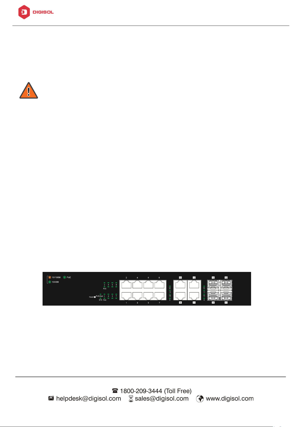
The following view applies to DG-GS1512HP.
1 2
Figure 1 - Front View
Page 13
DG-GS1512HP User Manual
11
No.
Name
Description
1
AC power in
Supports AC 100 – 240V, 50-60Hz.
No.
Name
Description
1
System
• Off: system not ready
• On: system ready
Blinking: system boot-up
The following view applies to DG-GS1512HP.
1
Figure 2 - Rear View
1.4.2. LED Indicators
The following view applies to DG-GS1512HP.
3 4
1 2
Figure 3 - Front View LED Indicators
Page 14

DG-GS1512HP User Manual
12
2
Power
• Off: power off
• On: power on
3
Port LED
LINK/ACT bi-color LED:
• Off: port disconnected or link fail
• Green on: 1000Mbps connected, PoE power output on
• Amber on: 10/100Mbps connected
• Blinking: sending or receiving data
4
SFP LED
• Off: port disconnected or link fail
• Green on: 1000Mbps connected
Page 15

DG-GS1512HP User Manual
13
2. Installation
This chapter describes how to install and connect your DG-GS1512HP Switch. Read the
following topics and perform the procedures in the correct order. Incorrect installation
may cause damage to the product.
2.1. Mounting the Switch
There are two ways to physically set up the switch.
• Place the switch on a flat surface. To place the switch on a desktop, install the
four rubber feet (included) on the bottom of the switch.
• Mount the switch in a standard rack (1 rack unit high).
2.1.1. Placement Tips
• Ambient Temperature—To prevent the switch from overheating, do not operate it
in an area that exceeds an ambient temperature of 122°F (50°C).
• Air Flow—Be sure that there is adequate air flow around the switch.
• Mechanical Loading—Be sure that the switch is level and stable to avoid any
hazardous conditions.
• Circuit Overloading—Adding the switch to the power outlet must not overload
that circuit.
Follow these guidelines to install the switch securely.
1. Put the switch in a stable place such as a desktop, to avoid it falling.
2. Ensure the switch works in the proper AC input range and matches the voltage
labeled.
3. Ensure there is proper heat dissipation from and adequate ventilation around the
switch.
4. Ensure the switch’s location can support the weight of the switch and its
accessories.
Page 16
DG-GS1512HP User Manual
14
Figure 4 - Desktop Installation
Page 17
DG-GS1512HP User Manual
15
2.1.2. Rack Mounting
You can mount the switch in any standard size, 19-inch (about 48 cm) wide rack. The
switch requires 1 rack unit (RU) of space, which is 1.75 inches (44.45 mm) high.
For stability, load the rack from the bottom to the top, with the heaviest
devices on the bottom. A top-heavy rack is likely to be unstable and may tip
over.
When mounting smaller switch products into a standard 19-inch rack, a pair
of extension brackets (sometimes referred to as ears) are needed to adapt
the switch to the rack size.
These extension brackets are mounted on the switch using the screws
provided in the kit, and have two holes that are used to then screw the
switch into the rack.
An example of one type of these extension brackets is shown in the following
figure.
A common problem that occurs during rack mounting is the distance between
the screw holes on the rack. Some racks are made with a uniform distance
between all of the holes, and others have the holes organized into groups
(see photo on the next page for an example).
When organized into groups, the switch must be placed in the rack so that
the holes in the extension brackets line up correctly.
1. Align the mounting brackets with the mounting holes on the switch’s side panels
and secure the brackets with the screws provided.
Figure 5 - Bracket Installation
Page 18
DG-GS1512HP User Manual
16
2. Secure the switch on the equipment rack with the screws provided.
Figure 6 - Rack Installation
Page 19

DG-GS1512HP User Manual
17
3. Getting Started
This section provides an introduction to the web-based configuration utility, and
covers the following topics:
• Powering on the device
• Connecting to the network
• Power over Ethernet (PoE) considerations
• Starting the web-based configuration utility
3.1. Power
3.1.1. Connecting to Power
Power down and disconnect the power cord before servicing or wiring a
switch.
Do not disconnect modules or cabling unless the power is first switched off.
The device only supports the voltage outlined in the type plate. Do not use
any other power components except those specifically designated for the
switch.
Disconnect the power cord before installation or cable wiring.
Page 20

DG-GS1512HP User Manual
18
The switch is powered by the AC 100-240 V 50/60Hz internal high-performance power
supply. It is recommended to connect the switch with a single-phase three-wire power
source with a neutral outlet, or a multifunctional computer professional source.
Connect the AC power connector on the back panel of the switch to the external
power source with the included power cord, and check the power LED is on.
Figure 7 - Rear View AC Power Socket
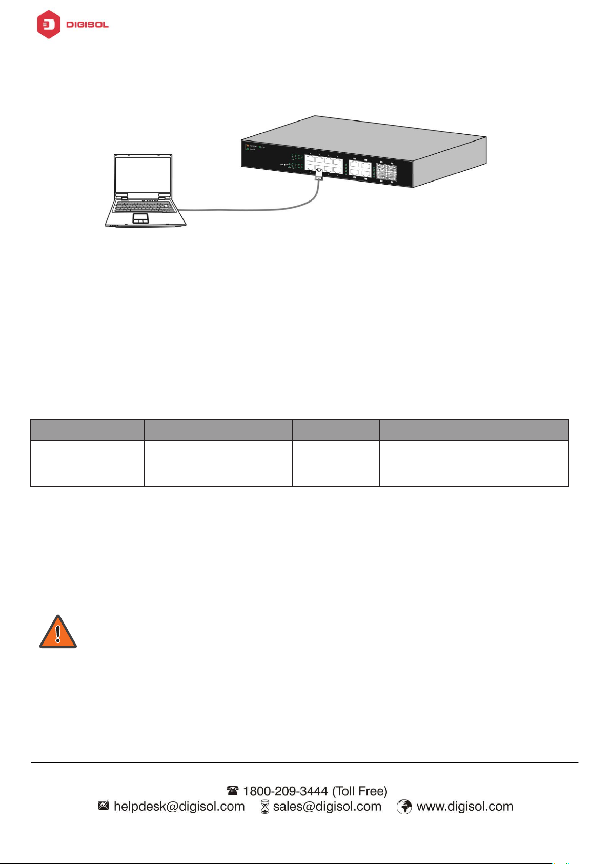
3.1.2. Connecting to the Network
To connect the switch to the network:
1. Connect an Ethernet cable to the Ethernet port of a computer
2. Connect the other end of the Ethernet cable to one of the numbered Ethernet
ports of the switch. The LED of the port lights if the device connected is
active.
3. Repeat Step 1 and Step 2 for each device to connect to the switch.
We strongly recommend using CAT-5E or better cable to connect network
devices. When connecting network devices, do not exceed the maximum
cabling distance of 100 meters (328 feet). It can take up to one minute
for attached devices or the LAN to be operational after it is connected.
This is normal behavior.
Connect the switch to end nodes using a standard Cat 5/5e Ethernet cable
(UTP/STP) to connect the switch to end nodes as shown in the illustration below.
Switch ports will automatically adjust to the characteristics (MDI/MDI-X, speed,
duplex) of the device to which the switch is connected.
Page 21
DG-GS1512HP User Manual
19
Model
Power Dedicated to
PoE Ports
PoE Standard Supported
DG-GS1512HP
140W
1 to 8
IEEE802.3at/af
Figure 8 - PC Connect
3.1.3. Power over Ethernet (PoE) Considerations
For PoE switch models, consider the following information:
Devices considered a Power Sourcing Equipment (PSE), can support up to 30 Watts
per PoE port to a Powered Device (PD).
Ports 1-8 provide PoE power supply functionality with a maximum output power up
to 30W each port. This can supply power to PDs such as internet phones, network
cameras, wireless access points. Connect the switch PoE port directly to the PD port
using a network cable.
When connecting switches capable of supplying PoE, consider the following
information:
• Switch models with PoE function are PSEs. These models are capable of
supplying DC power to attached PDs, such as VoIP phones, IP cameras,
and wireless access points (APs). PoE switches. Additionally, PoE switches
are capable of detecting and supplying power to pre-standard legacy PoE
Power Devices. Due to the support for legacy PoE, there is a possibility
that PoE switches acting as a PSE may inadvertently detect and supply
Page 22

DG-GS1512HP User Manual
20
power an attached PSE, including other PoE switches. This false detection
may result in a PoE switch operating improperly and unable to supply
power to attached PDs.
• The prevention of a false detection can be easily remedied by disabling
PoE on the ports that are used to connect PSEs. Another simple practice
to prevent a false detection is to first power up a PSE device before
connecting it to a PoE switch.
• When a device is falsely detected as a PD, disconnect the device from the
PoE port and power recycle the device with AC power before reconnecting
it to the PoE port.
3.1.4. Starting the Web-based Configuration Utility
This section describes how to navigate the web-based switch configuration utility.
Be sure to disable any pop-up blocker.
Browser Restrictions
• If you are using older versions of Internet Explorer, you cannot directly use an
IPv6 address to access the device. You can, however, use the DNS (Domain
Name System) server to create a domain name that contains the IPv6 address,
and then use that domain name in the address bar in place of the IPv6 address.
• If you have multiple IPv6 interfaces on your management station, use the IPv6
global address instead of the IPv6 link local address to access the device from
your browser.
Launching the Configuration Utility
To open the web-based configuration utility:
1. Open a Web browser.
2. Enter the IP address of the device you are configuring in the address bar on the
browser (factory default IP address is 192.168.1.10) and then press Enter.
When the device is using the factory default IP address, its power LED
flashes continuously. When the device is using a DHCP assigned IP address
Page 23
DG-GS1512HP User Manual
21
or an administrator-configured static IP address, the power LED is lit a
solid color. Your computer’s IP address must be in the same subnet as the
switch. For example, if the switch is using the factory default IP address,
your computer’s IP address can be in the following range: 192.168.1.x
(whereas x is a number from 2 to 254).
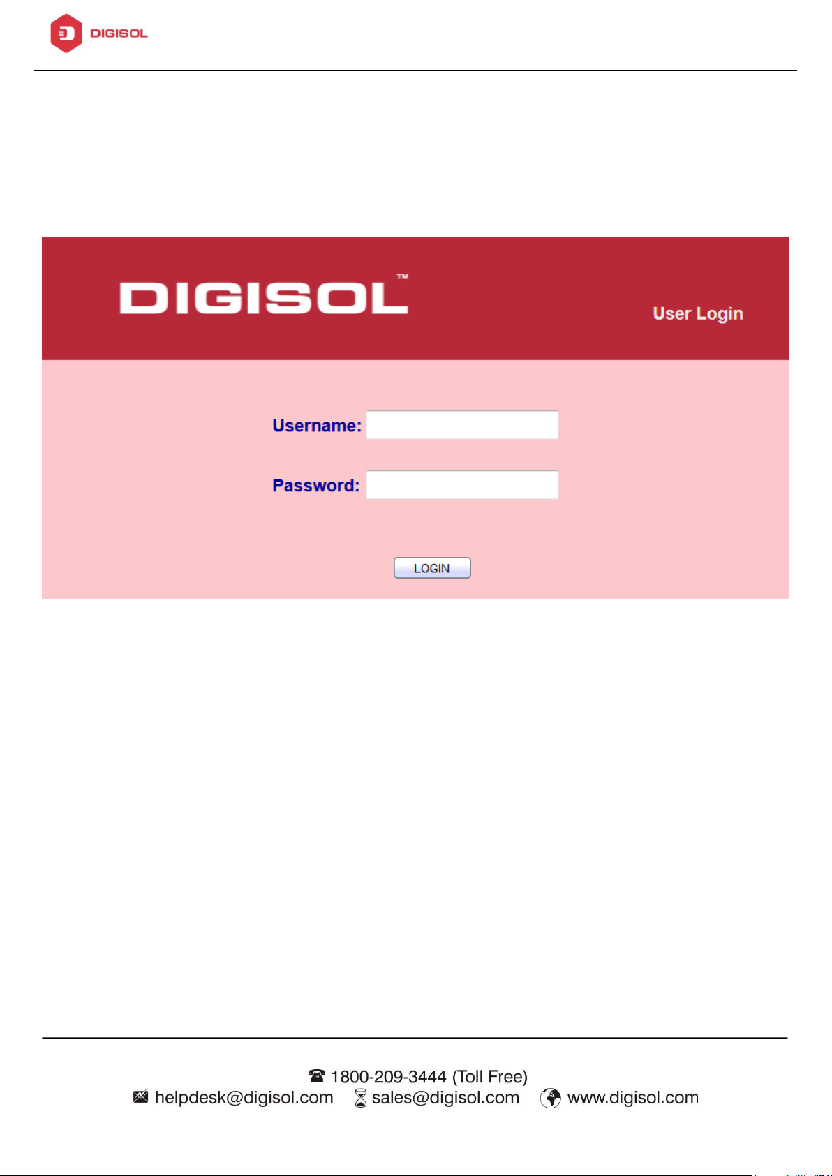
After a successful connection, the login window displays.
Figure 9 - Login Window
Page 24
DG-GS1512HP User Manual
22
3.1.5. Logging In
The default username is admin and the default password is admin. The first time that
you log in with the default username and password, you are required to enter a new
password.
To log in to the device configuration utility:
1. Enter the default user ID (admin) and the default password (admin).
2. If this is the first time that you logged on with the default user ID (admin) and
the default password (admin) it is recommended that you change your password
immediately.
When the login attempt is successful, the System Information window displays.
Figure 10 - System Information
If you entered an incorrect username or password, an error message appears and the
Login page remains displayed on the window. If you are having problems logging in,
please see the Launching the Configuration Utility section in the Administration Guide
for additional information.
Logging Out
Page 25

DG-GS1512HP User Manual
23
By default, the application logs out after ten minutes of inactivity.
To logout, click Logout in the top right corner of any page. The system logs out of the
device.
When a timeout occurs or you intentionally log out of the system, a message appears
and the Login page appears, with a message indicating the logged-out state. After
you log in, the application returns to the initial page.
Page 26
DG-GS1512HP User Manual
24
No.
Name
Description
1
Configuration
menu
Navigate to locate specific switch functions.
2
Configuration
settings
Edit specific function settings.
3
Switch’s current
link status
Green squares indicate the port link is up, while black
squares indicate the port link is down.
4
Common toolbar
Provides access to frequently used settings.
4
4. Web-based Switch Configuration
The PoE smart switch software provides rich Layer 2 functionality for switches in your
networks. This chapter describes how to use the web-based management interface
(Web UI) to configure the switch’s features.
For the purposes of this manual, the user interface is separated into four sections, as
shown in the following figure:
Figure 11 - User Interface
Page 27
DG-GS1512HP User Manual
25
Item
Description
Model
Model name of the switch.
System Name
System name of the switch. This name will also use as CLI
prefix of each line. (“Switch>” or “Switch#”).
4.1. Status
Use the Status pages to view system information and status.
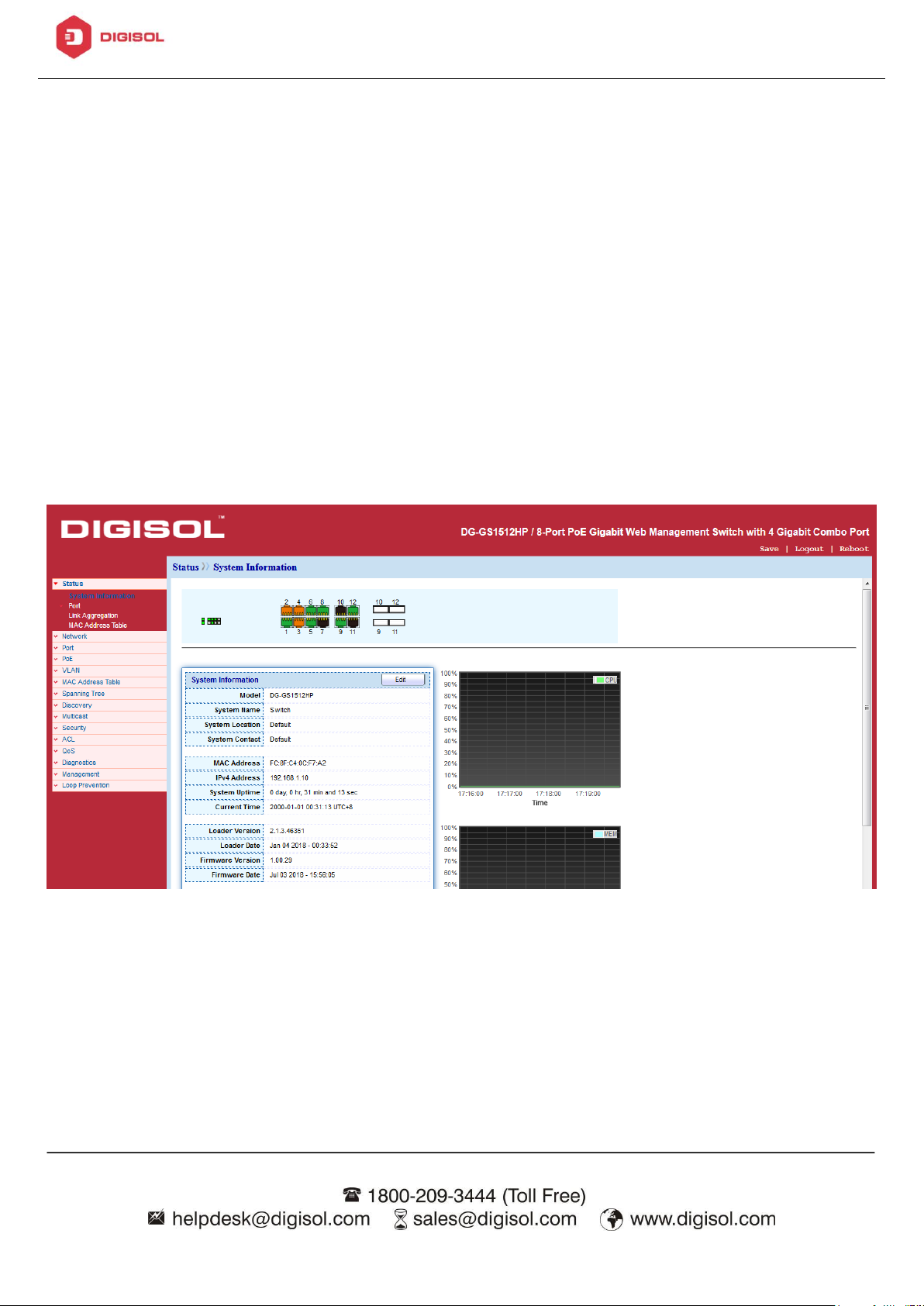
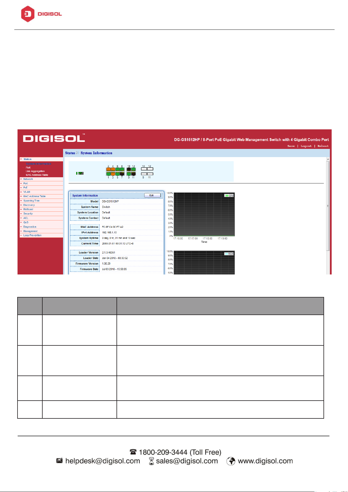
4.1.1. System Information
This page shows switch panel, CPU utilization, Memory utilization and other system
current information. It also allows user to edit some system information.
To display the Device Information web page, click Status > System
Information.
Figure 12 - Status > System Information
Page 28

DG-GS1512HP User Manual
26
System Location
Location information of the switch.
System Contact
Contact information of the switch.
MAC Address
Base MAC address of the switch.
IPv4 Address
Current system IPv4 address.
IPv6 Address
Current system IPv6 address.
System OID
SNMP system object ID.
System Uptime
Total elapsed time from booting.
Current Time
Current system time.
Loader Version
Boot loader image version.
Loader Date
Boot loader image build date.
Firmware Version
Current running firmware image version.
Firmware Date
Current running firmware image build date.
Telnet
Current Telnet service enable/disable state.
SSH
Current SSH service enable/disable state.
HTTP
Current HTTP service enable/disable state.
HTTPS
Current HTTPS service enable/disable state.
SNMP
Current SNMP service enable/disable state.
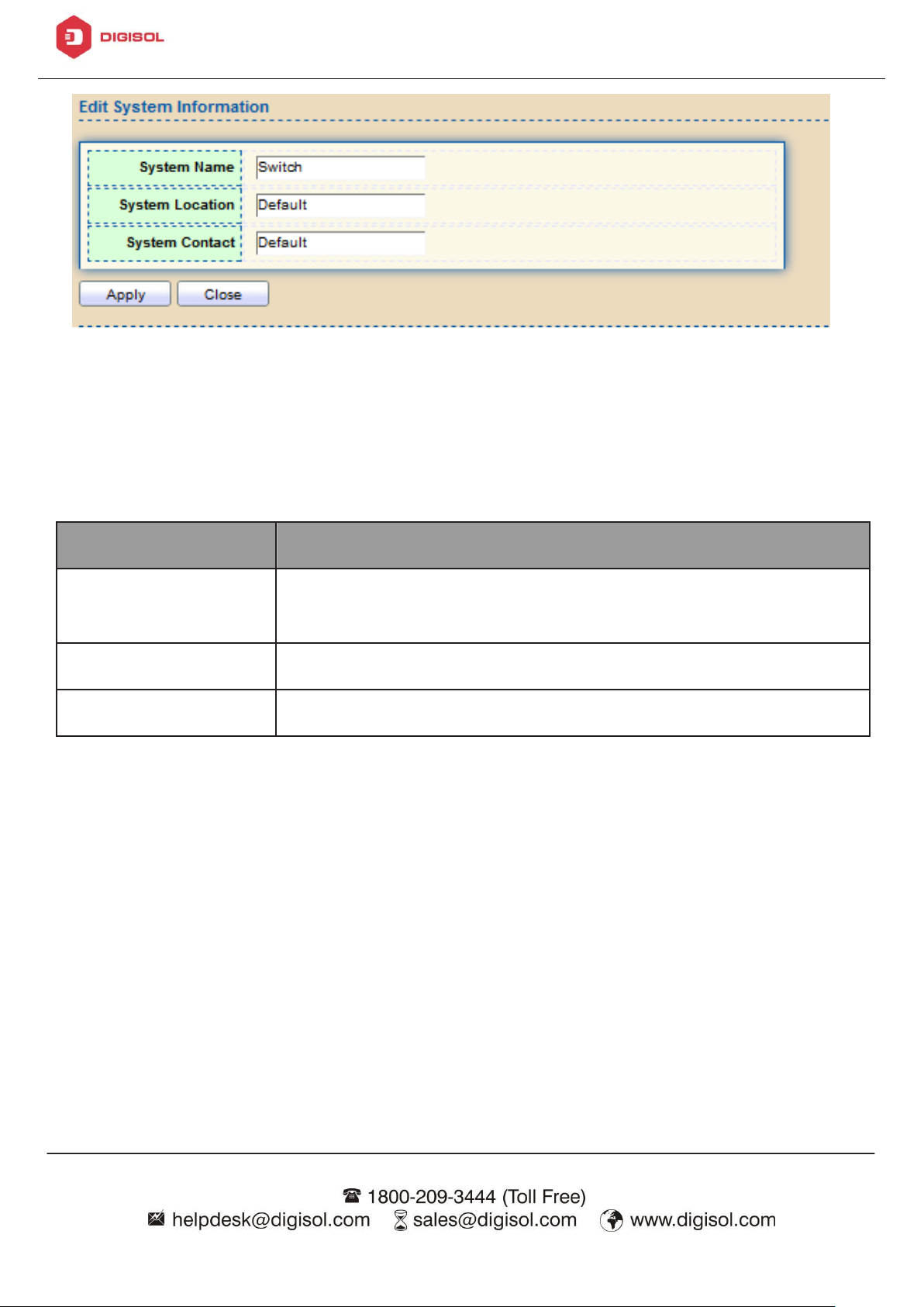
Click “Edit”button on the table title to edit following system information.
Page 29
DG-GS1512HP User Manual
27
Item
Description
System Name
System name of the switch. This name will also use as CLI
prefix of each line. (“Switch>” or “Switch#”).
System Location
Location information of the switch.
System Contact
Contact information of the switch.
Figure 13 - Status > System Information > Edit System Information
4.1.2. Port
The Port configuration page displays port summary and status information.
4.1.2.1. Statistics
This page displays standard counters on network traffic form the Interfaces,
Ethernet -like and RMONMIB. Interfaces and Ethernet-like counters display errors on
the traffic passing through each port. RMON counters provide a total count of
different frame types and sizes passing through each port. The “Clear” button will
clear MIB counter of current selected port.
Page 30
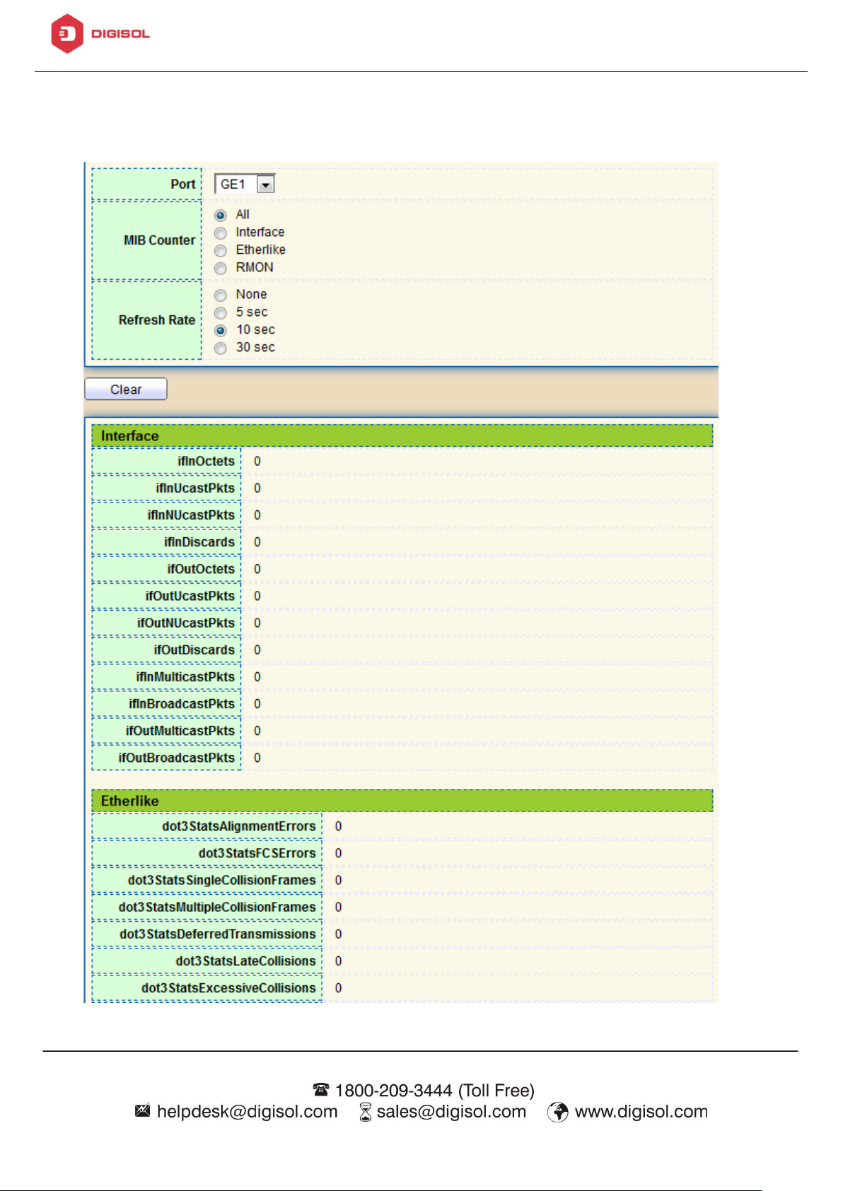
DG-GS1512HP User Manual
28
To display the Port Flow Chart web page, click Status > Port > Statistics.
Page 31
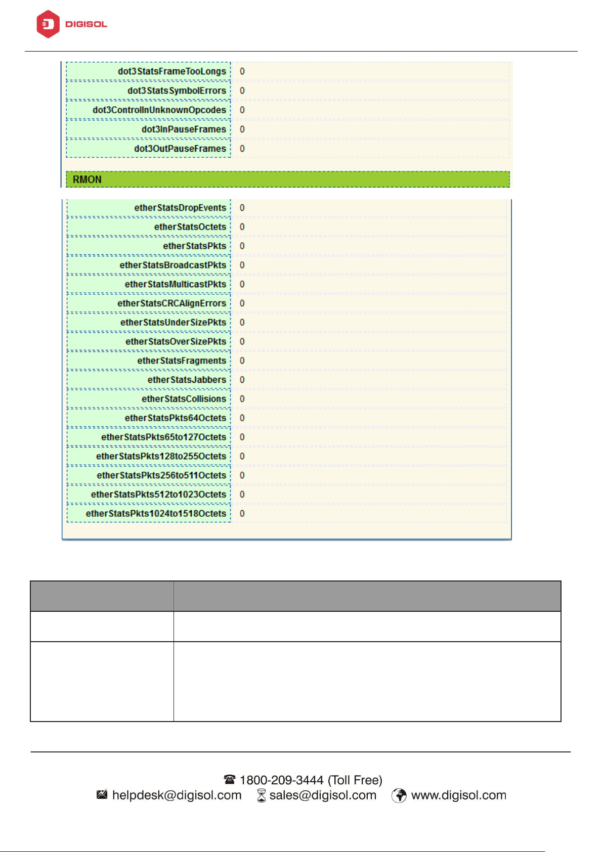
DG-GS1512HP User Manual
29
Item
Description
Port
Select one port to show counter statistics.
MIB Counter
Select the MIB counter to show different counter type
• All: All counters.
• Interface: Interface related MIB counters.
Figure 15 - Status > Port > Statistics
Page 32

DG-GS1512HP User Manual
30
• Etherlike: Ethernet-like related MIB counters.
• RMON: RMON related MIB counters.
Refresh Rate
Refresh the web page every period of seconds to get new
counter of specified port.
Item
Description
□
Select one or more port to operate.
Port
Interface or port number.
Reason
Port will be disabled by one of the following error reason:
• BPDU Guard
• UDLD
• Self Loop
• Broadcast Flood
• Unknown Multicast Flood
• Unicast Flood
4.1.2.2. Error Disabled
To display the Error Disabled web page, click Status > Port > Error Disabled.
Figure 16 - Status > Port > Error Disabled
Page 33

DG-GS1512HP User Manual
31
• ACL
• Port Security Violation
• DHCP rate limit
• ARP rate limit
Time Left (sec)
The time left in second for the error recovery.
Refresh
Refresh the current page.
Recover
Recover the selected port status.
4.1.2.3. Bandwidth Utilization
This page allow user to browse ports’ bandwidth utilization in real time. This page
will refresh automatically in every refresh period.
To display Bandwidth Utilization web page, click Status > Port > Bandwidth
Utilization.
Figure 17 - Status > Port > Bandwidth Utilization
Page 34

DG-GS1512HP User Manual
32
Item
Description
Refresh Rate
Refresh the web page every period of seconds to get new
bandwidth utilization data.
Item
Description
LAG
LAG Name.
Name
LAG port description.
Type
• The type of the LAG.
• Static: The group of ports assigned to a static LAG are
always active members.
• LACP: The group of ports assigned to dynamic LAG are
candidate ports. LACP determines which candidate ports
are active member ports.
4.1.3. Link Aggregation
To display the Link Aggregation web page, click Status > Link
Aggregation.
Figure 18 - Status > Link Aggregation
Page 35

DG-GS1512HP User Manual
33
Link Status
LAG port link status.
Active Member
Active member ports of the LAG.
Inactive Member
Inactive member ports of the LAG.
Item
Description
VLAN
VLAN ID of the mac address.
MAC Address
MAC address.
Type
The type of MAC address
• Management: DUT’s base mac address for
management Purpose.
• Static: Manually configured by administrator
• Dynamic: Auto learned by hardware.
4.1.4. MAC Address Table
The MAC address table page displays all MAC address entries on the switch including
static MAC address created by administrator or auto learned from hardware. The “
Clear” button will clear all dynamic entries and “Refresh” button will retrieve latest
MAC address entries and show them on page.
To display the MAC Address Table web page, click Status > MAC Address Table.
Figure 19 - Status > MAC Address Table
Page 36

DG-GS1512HP User Manual
34
Port
The type of Port
• CPU: DUT’s CPU port for management purpose.
• Other: Normal switch port.
4.2. Network
Use the Network pages to configure settings for the switch network interface and
how the switch connects to a remote server to get services.
4.2.1. IP Address
This section allows you to edit the IP address, Netmask, Gateway and DNS server
of the switch.
To view the IP Address menu, navigate to Network > IP Address.
Page 37

DG-GS1512HP User Manual
35
Figure 20 - Network > IP Address
Page 38

DG-GS1512HP User Manual
36
Item
Description
Address Type
The address type of switch IP configuration including
• Static: Static IP configured by users will be used.
• Dynamic: Enable the DHCP to obtain the IP address
from a DHCP server.
IP Address
Specify the switch static IP address on the static
configuration.
Subnet Mask
Specify the switch subnet mask on the static configuration.
Default Gateway
Specify the default gateway on the static configuration.
The default gateway must be in the same subnet with
switch IP address configuration.
DNS Server 1
Specify the primary user-defined IPv4 DNS server
configuration.
DNS Server 2
Specify the secondary user-defined IPv4 DNS server
configuration.
Table 3-2: IPv6 Address fields
IPv4 Address
The operational IPv4 address of the switch.
IPv4 Default
Gateway
The operational IPv4 gateway of the switch.
IPv6 Address v6
The operational IPv6 address of the switch.
IPv6 Gateway
The operational IPv6 gateway of the switch.
Link Local Address
The IPv6 link local address for the switch.
4.2.2. System Time
This page allow user to set time source, static time, time zone and daylight saving
settings. Time zone and daylight saving takes effect both static time or time from
Page 39

DG-GS1512HP User Manual
37
SNTP server.
To display System Time page, click Network > System Time
Figure 21 - Network > System Time
Page 40

DG-GS1512HP User Manual
38
Item
Description
Source
Select the time source.
• SNTP: Time sync from NTP server.
• From Computer: Time set from browser host.
• Manual Time: Time set by manually configure.
Time Zone
Select a time zone difference from listing district.
SNTP
Address Type
Select the address type of NTP server. This is enabled
when time source is SNTP.
Server Address
Input IPv4 address or hostname for NTP server. This is
enabled when time source is SNTP.
Server Port
Input NTP port for NTP server. Default is 123. This is
enabled when time source is SNTP.
Manual Time
Date
Input manual date. This is enabled when time source is
manual.
Time
Input manual time. This is enabled when time source is
manual.
Daylight Saving Time
Type
Select the mode of daylight saving time.
• Disable: Disable daylight saving time.
• Recurring: Using recurring mode of daylight saving time.
• Non-Recurring: Using non-recurring mode of daylight
saving time.
Page 41

DG-GS1512HP User Manual
39
• USA: Using daylight saving time in the United States
that starts on the second Sunday of March and ends on
the first Sunday of November.
• European: Using daylight saving time in the Europe that
starts on the last Sunday in March and ending on the
last Sunday in October.
Offset
Specify the adjust offset of daylight saving time.
Recurring From
Specify the starting time of recurring daylight saving time.
This field available when selecting “Recurring” mode.
Recurring To
Specify the ending time of recurring daylight saving time.
This field available when selecting “Recurring” mode.
Non-recurring
From
Specify the starting time of non-recurring daylight saving
time. This field available when selecting “Non-Recurring”
mode.
Non-recurring To
Specify the ending time of recurring daylight saving time.
This field available when selecting “Non-Recurring”
mode.
Non-recurring
From
Specify the starting time of non-recurring daylight saving
time. This field available when selecting “Non-Recurring
” mode.
Non recurring To
Specify the ending time of recurring daylight saving time.
This field available when selecting “ Non-Recurring ”
mode.
4.3. Port
Use the Port pages to configure settings for switch port related features.
4.3.1. Port Setting
Page 42

DG-GS1512HP User Manual
40
Item
Description
Port
Port Name.
Type
Port media type.
Description
Port Description.
State
Port admin state
• Enabled: Enable the port.
• Disabled: Disable the port.
Link Status
Current port link status
• Up: Port is link up.
• Down: Port is link down.
Speed
Current port speed configuration and link speed status.
This page shows port current status and allow user to edit port
configurations. Select port entry and click “Edit” button to edit port
configurations.
To display Port Setting web page, click Port > Port Setting
Figure 22 - Port > Port Setting
Page 43

DG-GS1512HP User Manual
41
Duplex
Current port duplex configuration and link duplex status.
Flow Control
Current port flow control configuration and link flow
control status.
Item
Description
Port
Selected Port list.
Description
Port media type.
State
Port admin state.
• Enabled: Enable the port.
• Disabled: Disable the port.
Speed
Port speed capabilities.
• Auto: Auto speed with all capabilities.
• Auto-10M: Auto speed with 10M ability only.
• Auto-100M: Auto speed with 100M ability only.
Click “Edit” button to edit Port Setting menu,
Figure 23 - Port > Port Setting > Port Setting
Page 44

DG-GS1512HP User Manual
42
• Auto-1000M: Auto speed with 1000M ability only.
• Auto-10M/100M: Auto speed with 10M/100M abilities.
• 10M: Force speed with 10M ability.
• 100M: Force speed with 100M ability.
• 1000M: Force speed with 1000M ability.
Duplex
Port duplex capabilities.
• Auto: Auto duplex with all capabilities.
• Half: Auto speed with 10M and 100M ability only.
• Full: Auto speed with 10M/100M/1000M ability only.
Flow Control
Port flow control.
• Auto: Auto flow control by negotiation.
• Enabled: Enable flow control ability.
• Disabled: Disable flow control ability.
4.3.2. Error Disable
To display Error Disabled web page, click Port > Error Disabled
Page 45

DG-GS1512HP User Manual
43
Item
Description
Recover Interval
Auto recovery after this interval for error disabled port.
BPDU Guard
Enabled to auto shutdown port when BPDU Guard reason
occur. This reason caused by STP BPDU Guard mechanism.
UDLD
Enabled to auto shutdown port when UDLD violation occur.
Self Loop
Enabled to auto shutdown port when Self Loop reason occur.
Broadcast Flood
Enabled to auto shutdown port when Broadcast Flood reason
occur. This reason caused by broadcast rate exceed
broadcast storm control rate.
Unknown Multicast
Flood
Enabled to auto shutdown port when Unknown Multicast
Flood reason occur. This reason caused by unknown
multicast rate exceed unknown multicast storm control rate.
Unicast Flood
Enabled to auto shutdown port when Unicast Flood reason
occur. This reason caused by unicast rate exceed unicast
storm control rate.
ACL
Enabled to auto shutdown port when ACL shutdown port
reason occur. This reason caused packet match the ACL
shutdown port action.
Port Security
Enabled to auto shutdown port when Port Security
Violation reason occur. This reason caused by violation
port security rules.
DHCP rate limit
Enabled to auto shutdown port when DHCP rate limit
reason occur. This reason caused by DHCP packet rate
exceed DHCP rate limit.
ARP rate limit
Enabled to auto shutdown port when ARP rate limit reason
occur. This reason caused by DHCP packet rate exceed
ARP rate limit.
Figure 24 - Port > Error disable
Page 46

DG-GS1512HP User Manual
44
Item
Description
Load Balance
Algorithm
LAG load balance distribution algorithm
• src-dst-mac: Based on MAC address.
• src-dst-mac-ip: Based on MAC address and IP address.
LAG
LAG Name.
Name
LAG port description.
Type
The type of the LAG
• Static: The group of ports assigned to a static LAG are
always active members.
• LACP: The group of ports assigned to dynamic LAG are
4.3.3. Link Aggregation
4.3.3.1. Group
This page allow user to configure link aggregation group load balance algorithm and
group member.
To view the Group menu, navigate to Port > Link Aggregation > Group.
Figure 25 - Port > Link Aggregation > Group
Page 47

DG-GS1512HP User Manual
45
candidate ports. LACP determines which candidate ports
are active member ports.
Link Status
LAG port link status
Active Member
Active member ports of the LAG.
Inactive Member
Inactive member ports of the LAG.
Item
Description
LAG
Selected LAG group ID.
Name
LAG port description.
Type
The type of the LAG
• Static: The group of ports assigned to a static LAG are
always active members.
• LACP: The group of ports assigned to dynamic LAG are
candidate ports. LACP determines which candidate ports
are active member ports.
Member
Select available port to be LAG group member port.
Click “Edit” to edit Link Aggregation Group menu.
Figure 26 - Port > Link Aggregation > Group > Edit Link Aggregation Group
Page 48

DG-GS1512HP User Manual
46
Item
Description
LAG
LAG Port Name.
Type
LAG Port media type.
Description
LAG Port description.
State
LAG Port admin state
• Enabled: Enable the port.
• Disabled: Disable the port.
Link Status
Current LAG port link status
• Up: Port is link up.
• Down: Port is link down.
4.3.3.2. Port Setting
This page shows LAG port current status and allow user to edit LAG port
configurations. Select LAG entry and click “Edit” button to edit LAG port
configurations.
To display LAG Port Setting web page, click Port > Link Aggregation > Port
Setting.
Figure 27 - Port > Link Aggregation > Port Setting
Page 49

DG-GS1512HP User Manual
47
Speed
Current LAG port speed configuration and link speed
status.
Duplex
Current LAG port duplex configuration and link duplex
status.
Flow Control
Current LAG port flow control configuration and link flow
control status.
Item
Description
Port
Selected Port list.
Description
Port description.
State
Port admin state
Click “Edit” to view Edit Port Setting menu.
Figure 28 - Port > Link Aggregation > Port Setting > Edit Port Setting
Page 50

DG-GS1512HP User Manual
48
• Enabled: Enable the port.
• Disabled: Disable the port.
Speed
Port speed capabilities
• Auto: Auto speed with all capabilities.
• Auto-10M: Auto speed with 10M ability only.
• Auto-100M: Auto speed with 100M ability only.
• Auto-1000M: Auto speed with 1000M ability only.
• Auto-10M/100M: Auto speed with 10M/100M abilities.
• 10M: Force speed with 10M ability.
• 100M: Force speed with 100M ability.
• 1000M: Force speed with 1000M ability.
Flow Control
Port flow control
• Auto: Auto flow control by negotiation.
• Enabled: Enable flow control ability.
• Disabled: Disable flow control ability.
4.3.3.3. LACP
This page allow user to configure LACP global and port configurations. Select ports
and click “Edit” button to edit port configuration.
To display the LACP Setting web page , click Port > Link Aggregation > LACP.
Page 51

DG-GS1512HP User Manual
49
Item
Description
System Priority
Configure the system priority of LACP. This decides the
system priority field in LACP PDU.
Port
Port Name.
Port Priority
LACP priority value of the port.
Timeout
The periodic transmissions type of LACP PDUs.
• Long: Transmit LACP PDU with slow periodic (30s).
• Short: Transmit LACPP DU with fast periodic (1s).
Figure 29 - Port > Link Aggregation > LACP
Click "Edit" button to view Edit LACP Port Setting menu.
Page 52

DG-GS1512HP User Manual
50
Item
Description
Port
Selected port list.
Port Priority
Enter the LACP priority value of the port
Timeout
The periodic transmissions type of LACP PDUs.
• Long: Transmit LACP PDU with slow periodic (30s).
• Short: Transmit LACPP DU with fast periodic (1s).
Figure 30 - Port > Link Aggregation > LACP > Edit LACP Port Setting
4.3.4. EEE
This page allow user to configure Energy Efficient Ethernet settings.
To display the EEE web page, click Port > EEE.
Page 53

DG-GS1512HP User Manual
51
Item
Description
Port
Port Name.
State
Port EEE admin state
• Enabled: EEE is enabled.
• Disabled: EEE is disabled.
Operational Status
Port EEE operational status
• Enabled: EEE is operating.
• Disabled: EEE is no operating.
Figure 31 - Port > EEE
Click “Edit” to edit the EEE menu.
Page 54

DG-GS1512HP User Manual
52
Item
Description
Port
Port Name
State
Port EEE admin state
• Enabled: EEE is enabled.
• Disabled: EEE is disabled.
Item
Description
Jumbo Frame
Enable or disable jumbo frame. When jumbo frame is
enabled, switch max frame size is allowed to configure. When
Figure 32 - Port > EEE > Edit EEE Setting
4.3.5. Jumbo Frame
This page allow user to configure switch jumbo frame size.
To display Jumbo Frame web page, click Port > Jumbo Frame
Figure 33 - Port > Jumbo Frame
Page 55

DG-GS1512HP User Manual
53
jumbo frame is disabled, default frame size 1522 will be used.
Item
Description
Nominal Power
Maximum supply power.
Consuming Power
Current consumed power.
Remaining Power
Remaining available power.
Schedule Status
Schedule status global switch.
Name
PoE Schedule Name.
4.4. PoE
PoE lets Ethernet cables supply power to network devices over the existing data
connection.
4.4.1. Global Setting
To display the Global web page, click PoE > Global Setting.
Figure 34 - PoE > Global Setting
Page 56

DG-GS1512HP User Manual
54
Port List
The ports provide power in designated schedule index.
Schedule Status
The current schedule status.
Item
Description
Index
The serial number of schedule list.
Schedule Status
Schedule Status
• Checked: Schedule status is enabled.
• Unchecked: Schedule status is disabled.
Name
Enter the PoE schedule name.
Date
Select a valid time for this schedule.
Port List
Select the port provide power.
Click “Edit” to view PoE Schedule List menu.
Figure 35 - PoE > Priority Setting > Edit PoE Schedule Edit
4.4.2. Priority Setting
Page 57

DG-GS1512HP User Manual
55
Item
Description
“L” is lower priority, “H” is high priority and “C” is Critical priority.
Click the port to change its priority status.
Use this section to set the power supply priority of PoE ports. Individual ports can be
assigned critical, high, or low power supply priority.
To display the Priority Setting web page, click PoE > Priority Setting.
Figure 36 - PoE > Priority Setting
4.4.3. Power Limit
To display the Power Limit web page, click PoE > Power Limit.
Figure 37 - PoE > Power Limit
Page 58

DG-GS1512HP User Manual
56
Item
Description
Port
Port name.
Power Limit
The max supply power for this port.
Item
Description
Port List
Selected port list.
Power Limit
Enter max supply power value for the selected port list.
Click “Edit” to view Power Limit Setting menu.
Figure 38 - PoE > Power Setting > Power Limit Setting Table
4.4.4. Power show
To display the Power Show web page, click PoE > Power Show.
Page 59

DG-GS1512HP User Manual
57
Item
Description
Per Port PoE Status
• Checked: Port PoE status is enabled.
• Unchecked: Port PoE status is disabled.
Figure 39 - PoE > Power Show
4.5. VLAN
A virtual local area network, virtual LAN or VLAN, is a group of hosts with a common
set of requirements that communicate as if they were attached to the same broadcast
domain, regardless of their physical location. A VLAN has the same attributes as a
physical local area network (LAN), but it allows for end stations to be grouped
together even if they are not located on the same network switch.VLAN membership
can be configured through software instead of physically relocating devices or
connections.
4.5.1. VLAN
Use the VLAN pages to configure settings of VLAN.
Page 60

DG-GS1512HP User Manual
58
Item
Description
Available VLAN
VLAN has not created yet.
Select available VLANs from left box then move to right
box to add.
Created VLAN
VLAN had been created.
Select created VLANs from right box then move to left box
to delete
4.5.1.1. Create VLAN
This page allows user to add or delete VLAN ID entries and browser all VLAN
entries that add statically or dynamic learned by GVRP. Each VLAN entry has a
unique name, user can edit VLAN name in edit page.
To display Create VLAN page, click VLAN > VLAN > Create VLAN
Figure 40 - VLAN > VLAN > Create VLAN
Page 61

DG-GS1512HP User Manual
59
VLAN
The VLAN ID.
Name
The VLAN Name.
Type
The VLAN Type.
Static: Port base VLAN.
Dynamic:802.1q VLAN。
Item
Description
Name
Input VLAN name.
Click “Edit” button to view Edit VLAN Name menu.
Figure 41 - VLAN > VLAN > Create VLAN > Edit VLAN Name
4.5.1.2. VLAN Configuration
This page allow user to configure the membership for each port of selected VLAN.
To display VLAN Configuration page, click VLAN > VLAN > VLAN Configuration.
Page 62

DG-GS1512HP User Manual
60
Item
Description
VLAN
Select specified VLAN ID to configure VLAN configuration.
Port
Display the interface of port entry.
Mode
Display the interface VLAN mode of port.
Membership
Select the membership for this port of the specified VLAN
ID.
• Forbidden: Specify the port is forbidden in the VLAN.
• Excluded: Specify the port is excluded in the VLAN.
• Tagged: Specify the port is tagged member in the VLAN.
• Untagged: Specify the port is untagged member in the
VLAN.
PVID
Display if it is PVID of interface.
Figure 42 - VLAN > VLAN > VLAN Configuration
Page 63

DG-GS1512HP User Manual
61
Item
Description
Port
Display the interface of port entry.
Mode
Display the interface VLAN mode of port.
Administrative
VLAN
Display the administrative VLAN list of this port.
Operational VLAN
Display the operational VLAN list of this port. Operational
VLAN means the VLAN status that really runs in device. It
may different to administrative VLAN.
4.5.1.3. Membership
This page allow user to view membership information for each port and edit
membership for specified interface.
To display Membership page, click VLAN > VLAN > Membership
Figure 43 - VLAN > VLAN > Membership
Click "Edit" button to view the Edit Port Setting menu
Page 64

DG-GS1512HP User Manual
62
Item
Description
Port
Display the interface.
Mode
Display the VLAN mode of interface.
Membership
Select VLANs of left box and select one of following
membership then move to right box to add membership.
Select VLANs of right box then move to left box to remove
membership. Tagging membership may not choose in differ
VLAN port mode. Select the time source.
• Forbidden: Set VLAN as forbidden VLAN.
• Excluded: This option is always disabled.
• Tagged: Set VLAN as tagged VLAN.
• Untagged: Set VLAN as untagged VLAN.
• PVID: Check this checkbox to select the VLAN ID to be
the port-based VLAN ID for this port. PVID may auto
select or can’t select in differ settings.
Figure 44 - VLAN > VLAN > Membership > Edit Port Setting
Page 65

DG-GS1512HP User Manual
63
Item
Description
Port
Display the interface.
Mode
Display the VLAN mode of interface.
PVID
Display the Port-based VLAN ID of port.
Accept Frame
Type
Display accept frame type of port.
Ingress Filtering
Display ingress filter status of port.
Uplink
Display uplink status.
TPID
Display TPID used of interface.
4.5.1.4. Port Setting
This page allow user to configure ports VLAN settings such as VLAN port mode,
PVID etc…The attributes depend on different VLAN port mode.
To display Port Setting page, click VLAN > VLAN > Port Setting
Figure 45 - VLAN > VLAN > Port Setting
Click “Edit” button to Edit Port Setting menu.
Page 66

DG-GS1512HP User Manual
64
Item
Description
Port
Display selected port to be edited.
Mode
Select the VLAN mode of the interface.
• Forbidden: Set VLAN as forbidden VLAN.
• Hybrid: Support all functions as defined in IEEE 802.1Q
specification.
• Access: Accepts only untagged frames and join an
untagged VLAN.
• Trunk: An untagged member of one VLAN at most, and
is a tagged member of zero or more VLANs.
PVID
Specify the port-based VLAN ID (1-4094). It’s only
available with Hybrid and Trunk mode.
Accepted Type
Specify the acceptable-frame-type of the specified
interfaces. It’s only available with Hybrid mode.
Ingress Filtering
Set checkbox to enable/disable ingress filtering. It’s only
available with Hybrid mode.
Figure 46 - VLAN > VLAN > Port Setting > Edit Port Setting
Page 67

DG-GS1512HP User Manual
65
Item
Description
State
Set checkbox to enable or disable voice VLAN function.
VLAN
Select Voice VLAN ID. Voice VLAN ID cannot be default
VLAN.
Cos/802.1p
Select a value of VPT. Qualified packets will use this VPT
value as inner priority.
4.5.2. Voice VLAN
Use the Voice VLAN pages to configure settings of Voice VLAN.
4.5.2.1. Property
This page allow user to configure global and per interface settings of voice VLAN.
To display Property Web page, click VLAN> Voice VLAN> Property
Figure 47 - VLAN > Voice VLAN > Property
Page 68

DG-GS1512HP User Manual
66
Remarking
Set checkbox to enable or disable 1p remarking. If
enabled, qualified packets will be remark by this value.
Aging Time
Input value of aging time. Default is 1440 minutes. A
voice VLAN entry will be age out after this time if without
any packet pass through.
Port Setting Table
Port
Display port entry.
State
Display enable/disabled status of interface.
Mode
Display voice VLAN mode.
QoS Policy
Display voice VLAN remark will effect which kind of packet.
Item
Description
Port
Display selected port to be edited.
State
Set checkbox to enable/disabled voice VLAN function of
Click “Edit” button to view Edit Port Setting menu.
Figure 48 - VLAN > Voice VLAN > Property > Edit Port Setting
Page 69

DG-GS1512HP User Manual
67
interface.
Mode
Select port voice VLAN mode
• Auto: Voice VLAN auto detect packets that match OUI
table and add received port into voice VLAN ID tagged
member.
• Manual: User need add interface to VLAN ID tagged
member manually.
QoS Policy
Select port QoS Policy mode
• Voice Packet: QoS attributes are applied to packets with
OUIs in the source MAC address.
• All: QoS attributes are applied to packets that are
classified to the Voice VLAN.
4.5.2.2. Voice OUI
This page allow user to add, edit or delete OUI MAC addresses. Default has 8 predefined OUI MAC.
To display the Voice OUI Web page, click VLAN > Voice VLAN > Voice OUI.
Figure 49 - VLAN > Voice VLAN > Voice OUI
Page 70

DG-GS1512HP User Manual
68
Item
Description
OUI
Display OUI MAC address.
Description
Display description of OUI entry.
Item
Description
OUI
Input OUI MAC address. Can’t be edited in edit dialog.
Description
Input description of the specified MAC address to the voice
VLAN OUI table.
Click “Add” or “Edit” button to Add/Edit Voice OUI menu.
Figure 50 - VLAN > Voice VLAN > Voice OUI > Add/Edit Voice OUI
Page 71

DG-GS1512HP User Manual
69
Item
Description
Group ID
Display group ID of entry.
MAC Address
Display mac address of entry.
Mask
Display mask of mac address for classified packet.
4.5.4. MAC VLAN
Use the MAC VLAN pages to configure settings of MAC VLAN.
4.5.4.1. MAC Group
This page allow user to add or edit groups settings of MAC VLAN.
To display the MAC page , click VLAN > MAC VLAN > MAC Group.
Figure 51 - VLAN > MAC VLAN > MAC Group
Click “Add” button or "Edit" button to view Add/Edit MAC menu.
Page 72

DG-GS1512HP User Manual
70
Item
Description
Group ID
Input group ID that is a unique ID of mac group entry.
The range from 1 to 2147483647. Only available on Add
Dialog.
MAC Address
Input mac address for classifying packets.
Mask
Input mask of mac address.
Item
Description
Port
Display port ID that binding with MAC group entry.
Figure 52 - VLAN > MAC VLAN > MAC Group > Add/Edit MAC
4.5.4.2. Group Binding
This page allow user to bind MAC VLAN group to each port with VLAN ID.
To display Group Binding page, click VLAN> MAC VLAN > Group Binding
Figure 53 - VLAN > MAC VLAN > Group Binding
Page 73

DG-GS1512HP User Manual
71
Group ID
Display group ID that port binding with.
VLAN
Display VLAN ID that assign to packets which match MAC
group.
Item
Description
Port
Select ports in left box then move to right to binding with
MAC group. Or select ports in right box then move to left
to unbind with MAC group. Only interface has hybrid VLAN
mode can be selected and bound with protocol group. Only
available on Add dialog.
Group ID
Select a Group ID to associate with port. Only available on
Add dialog.
VLAN
Input VLAN ID that will assign to packets which match
MAC group.
Click “Add” button to view the Add Group Binding menu.
Figure 54 - VLAN > MAC VLAN > Group Binding
Page 74
DG-GS1512HP User Manual
72
Item
Description
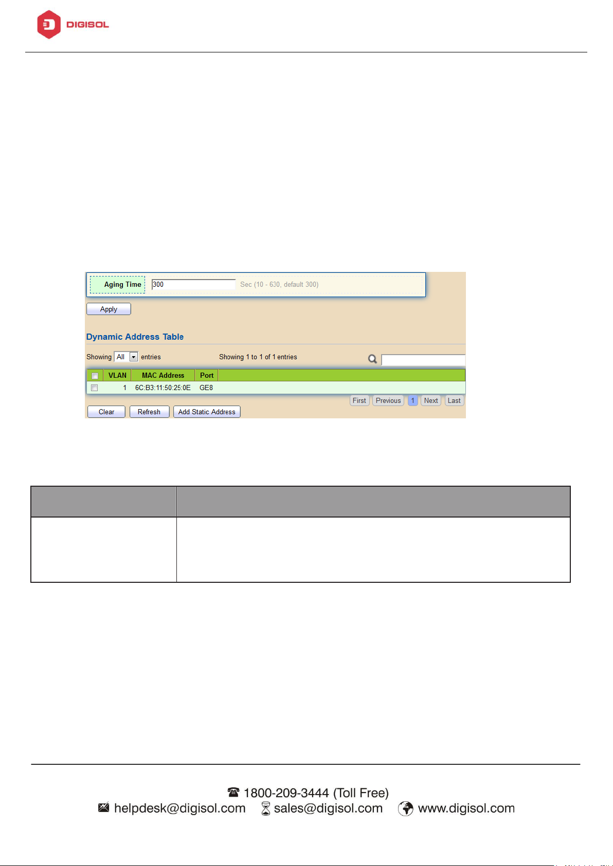
Aging Time
The time in seconds that an entry remains in the MAC
address table. Its valid range is from 10 to 630 seconds,
and the default value is 300 seconds.
4.6. MAC Address Table
Use the MAC Address Table pages to show dynamic MAC table and configure settings
for static MAC entries.
4.6.1. Dynamic Address
To display the Dynamic Address web page, click MAC Address Table > Dynamic
Address.
Figure 55 - MAC Address Table > Dynamic Address
4.6.2. Static Address
To display the Static Address web page, click MAC Address Table > Static
Address.
Page 75

DG-GS1512HP User Manual
73
Item
Description
MAC Address
The MAC address to which packets will be statically
forwarded.
VLAN
Specify the VLAN to show or clear MAC entries.
Port
Interface or port number.
Item
Description
MAC Address
Specify unicast MAC address in the packets to be dropped.
VLAN
Specify the VLAN to show or clear MAC entries.
Figure 56 - MAC Address Table > Static Address.
4.6.3. Filtering Address
To display the Filtering Address web page, click MAC Address Table > Filtering
Address.
Figure 57 - MAC Address Table > Filtering Address.
Page 76

DG-GS1512HP User Manual
74
4.7. Spanning Tree
The Spanning Tree Protocol (STP) is a network protocol that ensures a loop-free
topology for any bridged Ethernet local area network.
4.7.1. Property
To display the Property web page, click Spanning Tree > Property.
Figure 58 - Spanning Tree > Property
Page 77

DG-GS1512HP User Manual
75
Item
Description
State
Enable/disable the STP on the switch.
Operation Mode
Specify the STP operation mode.
• STP: Enable the Spanning Tree (STP) operation.
• RSTP: Enable the Rapid Spanning Tree (RSTP) operation.
• MSTP: Enable the Multiple Spanning Tree (MSTP)
operation.
Path Cost
Specify the path cost method.
• Long: Specifies that the default port path costs are
within the range:1-200,000,000.
• Short: Specifies that the default port path costs are
within the range:1-65,535.
BPDU Handling
Specify the BPDU forward method when the STP is
disabled.
• Filtering: Filter the BPDU when STP is disabled.
• Flooding: Flood the BPDU when STP is disabled.
Priority
Specify the bridge priority. The valid range is from 0 to
61440, and the value should be the multiple of 4096. It
ensures the probability that the switch is selected as the
root bridge, and the lower value has the higher priority for
the switch to be selected as the root bridge of the
topology.
Hello Time
Specify the STP hello time in second to broadcast its hello
message to other bridges by Designated Ports. Its valid
range is from 1 to 10 seconds.
Max Age
Specify the time interval in seconds for a switch to wait
the configuration messages, without attempting to
redefine its own configuration.
Forward Delay
Specify the STP forward delay time, which is the amount
of time that a port remains in the Listening and Learning
Page 78

DG-GS1512HP User Manual
76
states before it enters the Forwarding state. Its valid
range is from 4 to 10 seconds.
TX Hold Count
Specify the tx-hold-count used to limit the maximum
numbers of packets transmission per second. The valid
range is from 1 to 10.
Region Name
The MSTP instance name. Its maximum length is 32
characters. The default value is the MAC address of the
switch.
Revision
The MSTP revision number. Its valid rage is from 0 to
65535.
Max Hop
Specify the number of hops in an MSTP region before the
BPDU is discarded. The valid range is 1 to 40.
Operational Status
Bridge Identifier
Bridge identifier of the switch.
Designated Root
Identifier
Bridge identifier of the designated root bridge.
Root Port
Operational root port of the switch.
Root Path Cost
Operational root path cost.
Topology Change
Count
Numbers of the topology changes.
Last Topology
Change
The last time for the topology change.
4.7.2. Port Setting
To configure and display the STP port settings, click STP > Port Setting.
Page 79

DG-GS1512HP User Manual
77
Item
Description
Port
Specify the interface ID or the list of interface IDs.
State
The operational state on the specified port.
Path Cost
STP path cost on the specified port.
Priority
STP priority on the specified port.
BPDU Filter
The states of BPDU filter on the specified port.
BPDU Guard
The states of BPDU guard on the specified port.
Operational Edge
The operational edge port status on the specified port.
Operational
Point-to-Point
The operational point-to-point status on the specified port.
Port Role
The current port role on the specified port. The possible
values are: “Disabled”, “Master”, “Root”, “
Designated”, “Alternative”, and “Backup”.
Port State
The current port state on the specified port. The possible
values are: “Disabled”, “Discarding”, “Learning”,
and “Forwarding”.
Figure 59 - Spanning Tree > Port Setting
Page 80

DG-GS1512HP User Manual
78
Designated Bridge
The bridge ID of the designated bridge.
Designated Port
ID
The designated port ID on the switch.
Designated Cost
The path cost of the designated port on the switch.
Protocol
Migration Check
Restart the Spanning Tree Protocol (STP) migration
process (re-negotiate with its neighborhood) on the
specific interface.
Click "Edit" button to view Edit Port Setting menu.
Figure 60 - Spanning Tree > Port Setting > Edit Port Setting
Page 81

DG-GS1512HP User Manual
79
Item
Description
Port
Selected port ID.
State
Enable/Disable the STP on the specified port.
Path Cost
Specify the STP path cost on the specified port.
Priority
Specify the STP path cost on the specified port.
Edge Port
Specify the edge mode.
• Enable: Force to true state (as link to a host).
• Disable: Force to false state (as link to a bridge).
In the edge mode, the interface would be put into the
Forwarding state immediately upon link up. If the edge
mode is enabled for the interface and there are BPDUs
received on the interface, the loop might be occurred in
the short time before the STP state change.
BPDU Filter
The BPDU Filter configuration avoids receiving /
transmitting BPDU from the specified ports.
• Enable: Enable BPDU filter function.
• Disable: Disable BPDU filter function.
BPDU Guard
The BPDU Guard configuration to drop the received BPDU
directly.
• Enable: Enable BPDU guard function.
• Disable: Disable BPDU guard function.
Point-to-Point
Specify the Point-to-Point port configuration:
• Auto: The state is depended on the duplex setting of the
port
• Enable: Force to true state.
• Disable: Force to false state
Page 82

DG-GS1512HP User Manual
80
Item
Description
MSTI
Designated port number.
Priority
The bridge priority on the specified MSTI.
Bridge Identifier
The bridge identifier on the specified MSTI.
Designated Root
Bridge
The designated root bridge identifier on the specified
MSTI.
Root Port
The designated root port on the specified MSTI.
Root Path Cost
The designated root path cost on the specified MSTI.
4.7.3. MST Instance
To configure MST instance setting, click STP > MST Instance.
Figure 61 - Spanning Tree > MST Instance
Page 83

DG-GS1512HP User Manual
81
Remaining Hop
The configuration of remaining hop on the specified MSTI.
VLAN
The VLAN configuration on the specified MSTI.
Item
Description
VLAN
Select the VLAN list for the specified MSTI.
Priority
Specify the bridge priority on the specified MSTI. The valid
range is from 0 to 61440, and the value must be the
multiple of 4096. It ensures the probability that the switch
is selected as the root bridge, and the lower values has
the higher priority for the switch to be selected as the root
bridge of the STP topology.
Click "Edit" button to view Edit MST Instance menu.
Figure 62 - Spanning Tree > MST Instance > Edit MST Instance Setting
Page 84

DG-GS1512HP User Manual
82
Item
Descriptio
n
MSTI
Specify the port setting on the specified MSTI.
Port
Specify the interface ID or the list of interface IDs.
Path Cost
The port path cost on the specified MSTI.
Priority
The port priority on the specified MSTI.
Port Role
The current port role on the specified port. The possible
values are: “Disabled”, “Master”, “Root”, “
Designated”, “Alternative”, and “Backup”.
Port State
The current port state on the specified port. The possible
values are: “Disabled”, “Discarding”, “Learning”,
and “Forwarding”.
Mode
The operational STP mode on the specified port.
4.7.4. MST Port Setting
To configure and display MST port setting, click STP > MST Port Setting.
Figure 63 - Spanning Tree > MST Port Setting
Page 85

DG-GS1512HP User Manual
83
Type
The possible value for the port type are:
• Boundary: The port attaching an MST Bridge to a LAN
that is not in the same region.
• Internal: The port attaching an MST Bridge to a LAN that
is not in the same region.
Designated Bridge
The bridge ID of the designated bridge.
Designated Port ID
The designated port ID on the switch.
Designated Cost
The path cost of the designated port on the switch.
Remaining Hop
The remaining hops count on the specified port.
Click "Edit" button to view Edit MST Port Setting menu.
Figure 64 - Spanning Tree > MST Port Setting > Edit MST Port Setting
Page 86

DG-GS1512HP User Manual
84
Item
Description
Path Cost
Specify the STP port path cost on the specified MSTI.
Priority
Specify the STP port priority on the specified MSTI.
Item
Description
Refresh Rate
The option to refresh the statistics automatically.
Receive BPDU
(Config)
The counts of the received CONFIG BPDU.
4.7.5. Statistics
To display the STP statistics, click STP > Statistics.
Figure 65 - Spanning Tree > Statistics
Page 87

DG-GS1512HP User Manual
85
Receive BPDU
(TCN)
The counts of the received TCN BPDU.
Receive BPDU
(MSTP)
The counts of the received MSTP BPDU.
Transmit BPDU
(Config)
The counts of the transmitted CONFIG BPDU.
Transmit BPDU
(TCN)
The counts of the transmitted TCN BPDU.
Transmit BPDU
(MSTP)
The counts of the transmitted MSTP BPDU.
Clear
Clear the statistics for the selected interfaces
View
View the statistics for the interface.
Click "View" button to view the STP Port Statistic menu.
Page 88

DG-GS1512HP User Manual
86
Item
Description
Refresh Rate
The option to refresh the statistics automatically.
Clear
Clear the statistics for the selected interfaces.
Figure 66 - Spanning Tree > Statistics > STP Port Statistic
4.8. Discovery
Use this section to configure LLDP.
4.8.1. LLDP
LLDP is a one-way protocol; there are no request/response sequences.
Information is advertised by stations implementing the transmit function, and is
received and processed by stations implementing the receive function. The LLDP
category contains LLDP and LLDP-MED pages.
Page 89

DG-GS1512HP User Manual
87
Item
Description
State
Enable/ Disable LLDP protocol on this switch.
LLDP Handling
Select LLDP PDU handling action to be filtered, bridging or
flooded when LLDP is globally disabled.
• Filtering: Deletes the packet.
• Bridging: (VLAN-aware flooding) Forwards the packet to all
VLAN members.
• Flooding: Forwards the packet to all ports
TLV Advertise
Interval
Select the interval at which frames are transmitted. The
default is 30 seconds, and the valid range is 5–32767
seconds.
4.8.1.1. Property
To display LLDP Property Setting web page, click Discovery > LLDP > Property.
Figure 67 - Discovery > LLDP > Property
Page 90

DG-GS1512HP User Manual
88
Holdtime
Multiplier
Select the multiplier on the transmit interval to assign to TTL
(range 2–10, default = 4).
Reinitialization
Delay
Select the delay before a re-initialization (range 1–10
seconds, default = 2).
Transmit Delay
Select the delay after an LLDP frame is sent (range 1–8191
seconds, default = 3).
Fast Start Repeat
Count
Select fast start repeat count when port link up (range 1–10,
default = 3).
4.8.1.2. Port Setting
To display LLDP Port Setting, click Discovery > LLDP > Port Setting.
Figure 68 - Discovery > LLDP > Port Setting
Page 91

DG-GS1512HP User Manual
89
Item
Description
Port
Port Name.
Mode
The port LLDP mode.
Selected TLV
The Selected LLDP TLV.
Item
Description
Port
Select specified port or all ports to configure LLDP state.
Mode
Select the transmission state of LLDP port interface.
• Disable: Disable the transmission of LLDP PDUs.
Click "Edit" button to view Edit Port Setting menu.
Figure 69 - Discovery > LLDP > Port Setting > Edit Port Setting
Page 92

DG-GS1512HP User Manual
90
• RX Only: Receive LLDP PDUs only.
• TX Only: Transmit LLDP PDUs only.
• TX And RX: Transmit and receive LLDP PDUs both.
Optional TLV
Select the LLDP optional TLVs to be carried (multiple
selection is allowed).
• System Name
• Port Description
• System Description
• System Capability
• 802.3 MAC-PHY
• 802.3 Link Aggregation
• 802.3 Maximum Frame Size
• Management Address
• 802.1 PVID.
802.1 VLAN Name
Select the VLAN Name ID to be carried (multiple selection is
allowed).
4.8.1.3. Packet View
To display LLDP Overloading, click Discovery > LLDP > Packet View.
Page 93

DG-GS1512HP User Manual
91
Item
Description
Port
Port Name.
In-Use (Bytes)
Total number of bytes of LLDP information in each packet.
Available (Bytes)
Total number of available bytes left for additional LLDP
information in each packet.
Operational Status
Overloading or not.
Figure 70 - Discovery > LLDP > Packet View
Click "Detail" button to view Packet View Detail menu.
Page 94

DG-GS1512HP User Manual
92
Item
Description
Port
Port Name.
Mandatory TLVs
Total mandatory TLV byte size. Status is sent or overloading.
802.3 TLVs
Total 802.3 TLVs byte size. Status is sent or overloading.
Optional TLVs
Total Optional TLV byte size. Status is sent or overloading.
802.1 TLVs
Total 802.1 TLVs byte size. Status is sent or overloading.
Total
Total number of bytes of LLDP information in each packet.
Figure 71 - Discovery > LLDP > Packet View > Packet View Detail
Page 95

DG-GS1512HP User Manual
93
Item
Descriptio
n
Chassis ID Subtype
Type of chassis ID, such as the MAC address.
Chassis ID
Identifier of chassis. Where the chassis ID subtype is a
MAC address, the MAC address of the switch is displayed.
4.8.1.4. Local Information
Use the LLDP Local Information to view LLDP local device information.
To display LLDP Local Device, click Discovery > LLDP > Local Information.
Figure 72 - Discovery > LLDP > Local Information
Page 96

DG-GS1512HP User Manual
94
System Name
Name of switch.
System
Description
Description of the switch.
Capabilities
Supported
Primary functions of the device, such as Bridge, WLAN
AP, or Router.
Capabilities Enabled
Primary enabled functions of the device.
Port ID Subtype
Type of the port identifier that is shown.
LLDP Status
LLDP Tx and Rx abilities.
LLDP Med Status
LLDP MED enable state.
Click “Detail” button on the page to view detail information of the selected port.
Page 97

DG-GS1512HP User Manual
95
Figure 73 - Discovery > LLDP > Local Information > Detail
4.8.1.5. Neighbor
Use the LLDP Neighbor page to view LLDP neighbors information.
To display LLDP Remote Device, click Discovery > LLDP > Neighbor.
Page 98

DG-GS1512HP User Manual
96
Item
Description
Local Port
Number of the local port to which the neighbor is
connected.
Chassis ID
Subtype
Type of chassis ID (for example, MAC address).
Port ID Subtype
Type of the port identifier that is shown.
Port ID
Identifier of port.
System Name
Published name of the switch.
Time to Live
Time interval in seconds after which the information for
this neighbor is deleted.
Figure 74 - Discovery > LLDP > Neighbor
Click “detail” to view selected neighbor detail information
Page 99

DG-GS1512HP User Manual
97
Figure 75 LLDP Neighbor Detail Page
4.8.1.6. Statistics
The Link Layer Discovery Protocol (LLDP) Statistics page displays summary and
per-port information for LLDP frames transmitted and received on the switch.
Page 100

DG-GS1512HP User Manual
98
Item
Description
Insertions
The number of times the complete set of information
advertised by a particular MAC Service Access Point
(MSAP) has been inserted into tables associated with the
remote systems.
Deletions
The number of times the complete set of information
advertised by MSAP has been deleted from tables
associated with the remote systems.
Drops
The number of times the complete set of information
advertised by MSAP could not be entered into tables
associated with the remote systems because of insufficient
To display LLDP Statistics status, click Discovery > LLDP > Statistics.
Figure 76 - Discovery > LLDP > Statistics
 Loading...