

Page 1

XPON ONU Router with
1 PON and 1 Giga Port
DG-GR6010
V2.0
05-01-2021
Page 2

Copyright
Copyright 2020 by DIGISOL SYSTEMS LTD. All rights reserved.
Company has an on-going policy of upgrading its products and it may be
possible that information in this document is not up-to-date.
Please check with your local distributors for the latest information.
No part of this document can be copied or reproduced in any form without
written consent from the company.
Trademarks:
®
DIGISOL is a trademark of DIGISOL SYSTEMS LTD. All other trademarks
are the property of the respective manufacturers.
Page 3
Overview
1:1 Product Description
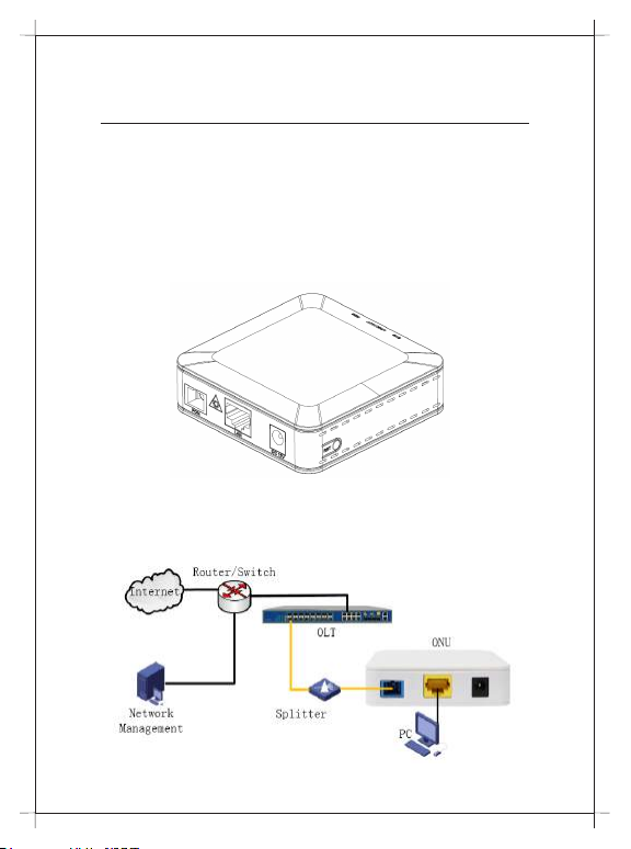
DG-GR6010 ONU meets telecom operators FTTO (Office), FTTD (Desk),
FTTH (Home) broadband speed, SOHO broadband access, video
surveillance and other requirements and design an EPON Gigabit Ethernet
products. It is based on mature and stable, cost-effective EPON technology,
high reliability, easy management, configuration flexibility and good quality
of service (QoS) guarantees to meet the technical performance of the
module IEEE802.3ah.
Figure 1 1GE
1:2 Application Chart
Figure 2Figure 2
Page 4
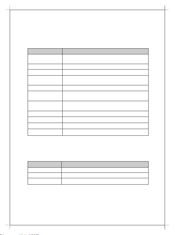
1:3 Technical Parameters
Technical Item DG-GR6010
PON interface 1 GPON / EPON connector, SC single-mode /
single-fiber,
Wavelength Tx:1310nm, Rx:1490nm
Optical interface SC/PC connector
LAN interface 1*10/100/1000Mbps auto adaptive Ethernet interfaces
RJ-45 connector
LED 3 For Status of PON, LAN, SYS
Operating condition Temperature: -10°C ~ +55°C
Humidity: 10% ~ 90% (non-condensing)
Storing condition Temperature: -30°C ~ 60°C
Humidity: 10% ~ 90% (non-condensing)
Power supply DC 12V/0.5A
Power consumption ≤4W
Dimension 82mm×82mm×25mm(L×W×H)
Net weight 0.08Kg
1:4 Package Content
Contents Quantity
ONU 1 PCS
Power Adapter 1 PCS
QIG 1 PCS
Page 5

Installation
2:1 Installation Requirements
● Connecting the optical fiber cable to the unit.
● Remove the protective cap of the optical fiber.
● Clean the end of the optical fiber with an optical fiber end cleaner.
● Remove the protective cap of the ONU optical interface
(PON interface). Connect the fiber to the PON port on the unit.
Note: When measuring the optical power before connecting to the
ONU, it is recommended to use a PON Inline Power Meter.
While connecting, please note:
● Keep the optical connector and the optical fiber clean.
● Make sure there are no tight bends in the fiber and that the bending
diameter is greater than 6cm. Otherwise, the optical signal loss may be
increased, to the extent that signal may be unavailable.
● Cover all optic ports and connectors with protective cap to guard
against dust and moisture when the fiber is not used.
● Apply power to the unit. Push the power button.
● After the ONU is power ON, Indicators should light up as for normal
operation. Check whether the PON interface status LED (PON) is on
continuously. If it is, the connection is normal; otherwise there is either
problem of the physical connection or the optical level at either end.
This may be caused by either too much or too little attenuation over
the optical fiber. Please refer to the Layout Description section of this
installation manual for normal LED activity.
● Check all signal levels and services on all the ONU communication
ports.
Installing the ONU on a horizontal surface (Bench top)
● Place the ONU on a clean, flat, sturdy bench top. You must keep the
clearance for all sides of the unit to more than 10cm for heat
dissipation.
● Installing the ONU on a vertical surface (Hanging on a wall)
● You can install the ONU on a vertical surface by using the mounting
holes on the bottom of the ONU chassis and two flat-head wood
screws.
Page 6
● Insert the screws into the wall. The screw positions must be in the
same horizontal line and the distance between them must be 145mm.
Reserved at least 6mm between the screw caps and the wall.
● Hang the ONU on the screws through the mounting holes.
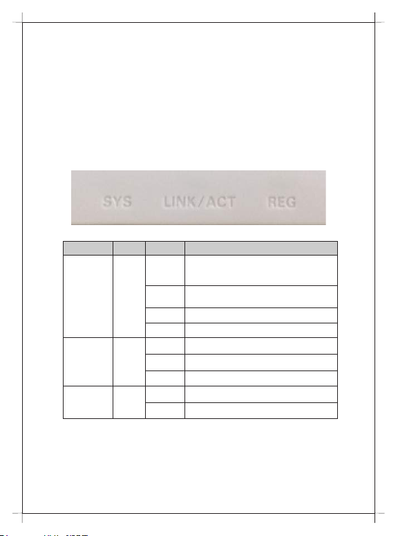
2:2 Panel Lights
LED Mark Status Description
On and
The device is registered to the PON system
Green in
colour
Off / Red
Registration
Interface
System SYS
REG
LINK/
ACT
Device is not registered to the PON system
in colour
Blink Device registration is incorrect
Fast Blink Port is sending or/and receiving data
On Port is connected properly (LINK)
Off Port connection exception or not connected
Blink Port is sending or/and receiving data (ACT)
On / Off System is not running or fatal error
Blink Normal running
Page 7

Web Management
● After finishing the basic connection configuration, you can use its basic
function. In order to satisfy individuation service requirements, this
charter provides the user parameter modification and individuation
configuration description.
● This model of ONU is designed as SFU (single family unit, bridge
mode), there is no bridge mode WAN in ONU. When it works on bridge
mode, VLAN of LAN port should be configured by OLT. When it works
on router mode, you may configure through its web management.
3:1 Default configuration
The following is the default device configuration information.
● Local (LAN access) Username: admin / Password: stdONUi0i
● LAN port management IP address: 192.168.1.1/24
Figure 3 Web Login
Web login default username: admin, password: stdONUi0i
Page 8

For security, you will be asked to modify password after you logged in by
default password. The new password must meet the requirements that
display on the webpage. After submitted, it requires you to login by new
password.
Figure 3 Change Password
Page 9

3:2 Status
This part shows the main information of product.
3.2.1 Device Information
3.2.1.1 Device Info
This page shows the device basic information, such as Software Version,
PON SN, LAN info, WAN info and so on.
Figure Device Info
Page 10

3.2.1.2 PON Status
This page shows the current system status of PON.
Figure PON Status
Page 11

3.2.1.3 Statistics
This page shows the packet statistics for transmission and reception
regarding to network interface.
Figure Statistics
3.2.1.4 Logout
This page is used to logout from the Device.
Figure Logout
Page 12

3:3 Setup
3.3.1 WAN
3.3.1.1 WAN Configuration
This page is used to configure the parameters for the WAN interface of
your ONU Router.
Note : Only when connect type of PPPoE is "Manual", the "Connect" and
"Disconnect"button will be enable.
Figure WAN Configuration
Page 13

3.3.2 LAN
3.3.2.1 LAN Interface Setup
This page is used to configure the LAN interface of your Router. Here you
may change the setting for IP address, subnet mask, etc..
Figure LAN Interface Setup
Page 14

3.3.2.2 DHCP Mode
This page can be used to config the DHCP mode:None,DHCP Relay or
DHCP Server.
(1) Enable the DHCP Server if you are using this device as a DHCP
server. This page lists the IP address pools available to host on your
LAN. The device distributes numbers in the pool to host on your network
as they request Internet access.
(2) Enable the DHCP Relay if you are using the other DHCP server to
assign IP address to your host on the LAN. You can set the DHCP server
IP address.
(3) If you choose "None", then the modem will do nothing when the host
request a IP address.
Figure DHCP Settings
Page 15

3:4 Maintenance
3.4.1 Upgrade Firmware
This page allows you upgrade the Router firmware to new version.
Please note, do not power off the device during the upload because it
may crash the system.
Note: System will reboot after file is uploaded.
3.4.2 Backup/Upload Settings
Once the router is configured you can save the configuration settings to a
configuration file on your hard drive. You also have the option to load
configuration settings.
Figure Backup/Upload Settings
Page 16

3.4.3 Reboot/Restore
This page is used to reboot your system or restore to default setting.
Figure Reboot / Restore
Page 17

Troubleshooting
1. After power all the lights are lit?
Reasons:
1) Power connection errors
2) Power is not normal. Solution:
1) Check that the power cable is connected
2) The rear panel of the power supply is turned on.
2. GE / FE led does not light?
Reasons:
1) Network cable is damaged or loose connection
2) Cable type error;
3) Long lines outside the allowable range. Solution:
1) Replace the network cable, and pay attention to the standard
Ethernet cable must be parallel or crossing lines.
3. After working for some time to stop working?
Reasons:
1) Power supply is not working properly
2) The equipment from overheating. Solution:
1) Check if there is contact with abnormal voltage is too high or too low;
2) Check the ambient conditions, vents are normal ventilation.
4. LOS led flashes?
Reasons:
1) Fiber failure;
2) Central office equipment failure. Solution:
1) Inspect fiber is connected properly, is connected to the correct
connector, optical power is normal.
2) Contact your operator.
5. PON led flashes?
Reasons:
1) Fiber optic connector is loose;
2) Central office equipment failure;
3) Fiber optic connectors are dust. Solution:
1) Inspect fiber is connected properly;
2) Cotton ball with alcohol swabbing fiber optic connectors;
3) Contact your operator.
Page 18

Page 19

Page 20

DIGISOL SYSTEMS LIMITED
L-7, Verna Industrial Estate,
Salcete, GOA - 403722
www.digisol.com
Digisol is a Subsidiary of Smartlink Holdings Limited
1800 209 3444
helpdesk@digisol.com
 Loading...