

Page 1
DG-FS1510HPE
8 PORT 10/100 MBPS WEB MANAGED POE SWITCH, 2
COMBO GBE PORTS
User Manual
V1.0
2015-05-11
As our products undergo continuous development the specifications are subject to change without prior notice
Page 2

DG-FS1510HPE User Manual
2
COPYRIGHT
Copyright 2015 by Smartlink Network Systems Ltd. No part of this publication
may be reproduced, transmitted, transcribed, stored in a retrieval system, or
translated into any language or computer language, in any form or by any means,
electronic, mechanical, magnetic, optical, chemical, manual or otherwise, without
the prior written permission of this company.
This company makes no representations or warranties, either expressed or implied,
with respect to the contents hereof and specifically disclaims any warranties,
merchantability or fitness for any particular purpose. Any software described in
this manual is sold or licensed "as is". Should the programs prove defective
following their purchase, the buyer (and not this company, its distributor, or its
dealer) assumes the entire cost of all necessary servicing, repair and any incidental
or consequential damages resulting from any defect in the software. Further, this
company reserves the right to revise this publication and to make changes from
time to time in the contents thereof without obligation to notify any person of such
revision or changes.
Trademarks:
DIGISOL™ is a trademark of Smartlink Network Systems Ltd. All other
trademarks are the property of the respective manufacturers.
Safety
This equipment is designed with the utmost care for the safety of those who install
and use it. However, special attention must be paid to the dangers of electric shock
and static electricity when working with electrical equipment. All guidelines of this
and of the computer manufacturer must therefore be allowed at all times to ensure
the safe use of the equipment.
Page 3

DG-FS1510HPE User Manual
3
Index
1 Precautions ...................................................................................................... 6
2 Overview......................................................................................................... 7
2.1 Product Features .................................................................................. 7
3 Technical Specifications ................................................................................... 8
3.1 Environment Requirements .................................................................. 8
3.2 Power Interface.................................................................................... 8
3.3 Power Consumption ............................................................................. 8
3.4 Ethernet Interface ................................................................................ 8
3.5 Physical Characteristics ....................................................................... 9
4 Device Installation and Description ................................................................ 10
4.1 Preparation Before Installation ........................................................... 10
4.1.1 Package Contents .................................................................. 10
4.1.2 Optional Accessories and Tools .............................................. 10
4.1.3 Choosing the Installation Location ......................................... 10
4.1.3.1 Installing the DG-FS1510HPE on the Work Platform .. 10
4.1.3.2 Installing the DG-FS1510HPE on a Rack ................... 11
4.2 Hardware Description ........................................................................ 11
4.2.1 Front Panel ........................................................................... 11
4.2.2 Rear Panel............................................................................. 13
4.3 Electrical Setup.................................................................................. 13
4.3.1 Setting Up the Power Interface ............................................... 13
4.3.2 Setting Up the Ethernet Interfaces .......................................... 13
5 Device Startup ............................................................................................... 14
5.1 Check Before Power-On .................................................................... 14
5.2 Powering On the Device .................................................................... 14
6 Device Upgrade ............................................................................................. 14
7 Web Configuration and Management .............................................................. 15
7.1 Preparation Before Login ................................................................... 15
7.2 Logging In to the Switch .................................................................... 16
7.3 System Management .......................................................................... 17
7.3.1 Authentication Configuration ................................................. 18
7.3.2 System IP Configuration......................................................... 19
7.3.3 System Status ......................................................................... 20
Page 4

DG-FS1510HPE User Manual
4
7.3.4 Loading Default Settings ........................................................ 20
7.3.5 Firmware Update ................................................................... 21
7.3.6 Reboot the Device ................................ .................................. 21
7.4 POE .................................................................................................. 22
7.4.1 PoE Status ............................................................................. 22
7.4.2 PoE Setting ............................................................................ 23
7.4.3 PoE Power Delay .................................................................. 24
7.4.4 PoE Scheduling...................................................................... 25
7.4.5 NTP Setting ........................................................................... 25
7.5 Port Management ............................................................................... 26
7.5.1 Port Configuration ................................................................. 26
7.5.2 Port Mirroring ....................................................................... 27
7.5.3 Bandwidth Control ................................................................. 28
7.5.4 Broadcast Storm Control ........................................................ 29
7.6 VLAN Setting ................................................................................... 29
7.6.1 VLAN Mode ........................................................................... 30
7.6.1.1 VLAN Based on Port .................................................. 30
7.6.2 VLAN Member ....................................................................... 30
7.6.2.1 VLAN Based on Port .................................................. 30
7.6.2.2 VLAN Based on Tag ................................................... 31
7.6.3 Multi to 1 Setting Configuration ............................................. 33
7.7 Per Port Counter ................................................................................ 34
7.8 QoS Configuration ................................ ............................................. 35
7.8.1 Priority Mode ........................................................................ 36
7.8.2 Class of Service Configuration - 1 .......................................... 37
7.8.3 Class of Service Configuration - 2 .......................................... 38
7.9 Security ............................................................................................. 40
7.9.1 MAC Address Binding ............................................................ 40
7.9.2 TCP/UDP Filter..................................................................... 41
7.10 Spanning Tree.................................................................................. 42
7.10.1 STP Bridge Settings ............................................................. 43
7.10.2 STP Port Settings ................................................................. 45
7.10.3 Loopback Detection: ............................................................ 47
7.11 Trunking .......................................................................................... 49
7.12 DHCP Relay Agent .......................................................................... 51
Page 5

DG-FS1510HPE User Manual
5
7.12.1 DHCP Relay Agent .............................................................. 51
7.12.2 Relay Server ........................................................................ 52
7.12.3 VLAN MAP Relay Agent ....................................................... 52
7.13 Configuration Backup and Recovery ................................................ 53
7.14 Miscellaneous Configuration ............................................................ 54
7.15 SNMP Settings ................................................................ ................ 55
7.16 Logout ............................................................................................ 56
8 Troubleshooting ............................................................................................. 56
9 Glossary ........................................................................................................ 57
Page 6

DG-FS1510HPE User Manual
6
1 Precautions
Power supply sockets with too heavy load or broken cables and plugs
may cause electric shock or fire. Users should check the power supply
wires and cables regularly. If there is any breakage, please replace the
cable at once.
Do not open the case of the device, especially during device power-on.
The device should be installed at position with good ventilation and
without high temperature or direct sunshine, so as to avoid faults of the
device and its corresponding components due to overheat.
Do not put this device close to a damp or watery place. Do not spill
any fluid on this device.
Keep proper space for heat dissipation, to avoid any damage to the
device caused by overheating. The holes on the shell are designed for
heat dissipation, to ensure that the device works normally. Do not
cover the heat dissipation holes.
Keep the power plug clean and dry, if abnormal phenomenon occurs,
such as smoke, abnormal sound, abnormal smell, switch off the power.
Page 7

DG-FS1510HPE User Manual
7
2 Overview
The DG-FS1510HPE is an intelligent Layer 2 Ethernet switch. It provides 8 10M/100M
self-adaptive Ethernet ports and 2 gigabit combo ports. The combo ports can be flexibly
connected to gigabit copper cable or backbone fiber. You can select 1000BASE-LX,
1000BASE-SX or 1000BASE-T interface according to the transmission distance. The
DG-FS1510HPE supports VLAN classification,DHCP, port counter, port trunking and
QoS. You can configure the device easily through web interface.
2.1 Product Features
8 10M/100M self-adaptive FE ports and 2 10M/100M/1000M self-adaptive GE
ports. 2 SFP slots are shared with GE ports. You can connect the switch to other
switches through copper cable or fiber.
Manage the switch through web page. Network administrator can monitor and
configure the switch through any Ethernet port.
Supports the following standards: IEEE802.3at and IEEE802.3af standard
VLAN: Supports up to 32 Tag VLANs and up to 26 Port Based VLANs.
Supports 4K MAC addresses.
Other functions: CoS, broadcast storm control, port management, bandwidth
control, spanning tree protocol and simple network management.
Page 8

DG-FS1510HPE User Manual
8
3 Technical Specifications
3.1 Environment Requirements
The whole device can survive in a wide range of operating temperature and can work
normally and stably in tough environment.
Operating temperature: 0˚C—50˚C
Storage temperature: -40˚C—70˚C
Relative humidity: 10%—90% RH (non-condensing)
3.2 Power Interface
Power input: 100V AC ~240V AC, 50/60Hz
3.3 Power Consumption
Whole device consumption: < 180 W
3.4 Ethernet Interface
Standard: IEEE802.3at and IEEE802.3af.
Transmission rate: Port 1 ~ Port 8 are 10 M/100 M self-adaptive.
Port 9 ~ Port 10 are 10 M/100 M/1000 M self-adaptive.
Working mode: full duplex, half duplex, self-adaptive.
Port type: 8 x 10/100Base-TX self-adaptive Ethernet ports. 2 x SFP fiber
ports. They are shared with 10/100/1000Base-TX self-adaptive Ethernet
ports.
Transmission distance: < 100m, Cat. 3/5 UTP. The transmission distance of
SFP port is determined by optical module.
Auto-MDI/MDI-X. Automatically distinguish crossover cable from straight
through cable.
Page 9

DG-FS1510HPE User Manual
9
3.5 Physical Characteristics
Dimensions: 330(W) x 44(H) x 230(D) mm
Net Weight: 2.5 kgs
Page 10

DG-FS1510HPE User Manual
10
4 Device Installation and Description
4.1 Preparation Before Installation
4.1.1 Package Contents
DG-FS1510HPE Fast Ethernet Switch
Power Cord
Bracket Mounting Kit containing two brackets and six screws for attaching
the brackets to the switch
CD containing User Manual
Four adhesive foot pads
4.1.2 Optional Accessories and Tools
Screwdriver
ESD straps
Ethernet crimping pliers, crystal heads
Ethernet (either crossover or straight through) cable
4.1.3 Choosing the Installation Location
The DG-FS1510HPE can be installed in either of the following ways as required:
On the work platform
On a rack
4.1.3.1 Installing the DG-FS1510HPE on the Work Platform
The common way is to install the DG-FS1510HPE on a clean work platform. Pay attention
to the following precautions:
Ensure that the work platform is flat and stable.
Ensure good ventilation of air ports on both sides of the device.
Do not put heavy objects on the device.
Page 11
DG-FS1510HPE User Manual
11
4.1.3.2 Installing the DG-FS1510HPE on a Rack
Before installing the DG-FS1510HPE on a rack, you need to install the provided LClamps on both sides of the DG-FS1510HPE.
4.2 Hardware Description
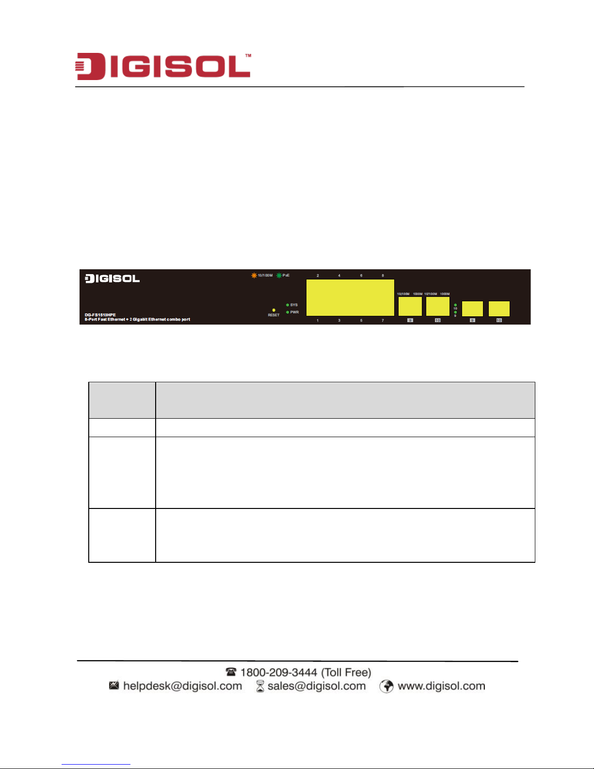
4.2.1 Front Panel
The following table describes the interfaces of the DG-FS1510HPE.
Interface
/Button
Description
Ports 1~8 8 x RJ-45 Ethernet interfaces, 10 M/100 M self-adaptive.
Ports 9, 10
Two groups of fiber-copper combo ports. The copper ports are 10 M/100
M/1000 M self-adaptive Ethernet ports and the fiber ports are SFP optical
module ports. If the combo ports are preferred to serve as fiber ports, that is,
if the ports connect to a fiber port, the copper port is disabled.
Reset
Keep the device powered on and push a paper clip into the hole. Press down
the button for about 5 seconds. The system restores the factory default
settings.
Page 12
DG-FS1510HPE User Manual
12
The following table describes the LED indicators of the DG-FS1510HPE.
Interface/Button
Status/Color
Description
PWR
Green (ON)
Power ON.
OFF
Power OFF.
Ports (1-8)
(Link/Activity LED)
Amber (OFF)
Port disconnected or link fail.
ON
Port Connected.
Blinking
Sending or receiving data.
Ports (1-8) (PoE
LED)
Green (OFF)
PoE power OFF.
ON
PoE power ON.
10/100/1000
Copper ports LED’s
OFF
Port disconnected or link fail.
Green (ON)
1000Mbps connected.
Amber (ON)
10/100 Mbps connected.
BLinking
Sending or receiving data.
SFP Ports LED’s
OFF
Port disconnected or link fail.
Green (ON)
1000FX connected.
Blinking
Sending or receiving data.
Page 13

DG-FS1510HPE User Manual
13
4.2.2 Rear Panel
Interface
Description
100-240VAC 50/60Hz
The power interface.
The power input is 100 V ~ 240 V AC, 50 Hz ~ 60Hz.
4.3 Electrical Setup
4.3.1 Setting Up the Power Interface
After placing the DG-FS1510HPE to a flat and stable surface, insert the supplied power
cord to the power socket, and connect the other end of the cable to the power interface of
DG-FS1510HPE.
4.3.2 Setting Up the Ethernet Interfaces
The DG-FS1510HPE provides 10 Ethernet service interfaces of standard RJ45 connectors.
You can use either the crossover or straight through cable to connect an interface.
Note:
To ensure good quality of the data signal, the length of the network cable
connected to the Ethernet interface should be shorter than 100m.
Page 14

DG-FS1510HPE User Manual
14
5 Device Startup
5.1 Check Before Power-On
Before powering on the device, check the following:
Whether the voltage of the power supply is consistent with the power
requirement of the device.
Whether the power cord is correctly connected.
Whether the device is correctly connected to the ground on the rear side.
5.2 Powering On the Device
After connecting the power cable, turn on the power switch. When the Power indicator
turns on, the system starts to initialize. When other indicators blink three times and the
Power indicator is always on in green, the switch works normally.
6 Device Upgrade
You can upgrade the software through any Ethernet port for DG-FS1510HPE. After
software upgrade is complete, the system reboots automatically.
Page 15
DG-FS1510HPE User Manual
15
7 Web Configuration and Management
The system does not support the CLI and telnet management. It supports the web
management only. This section describes the web configuration and management.
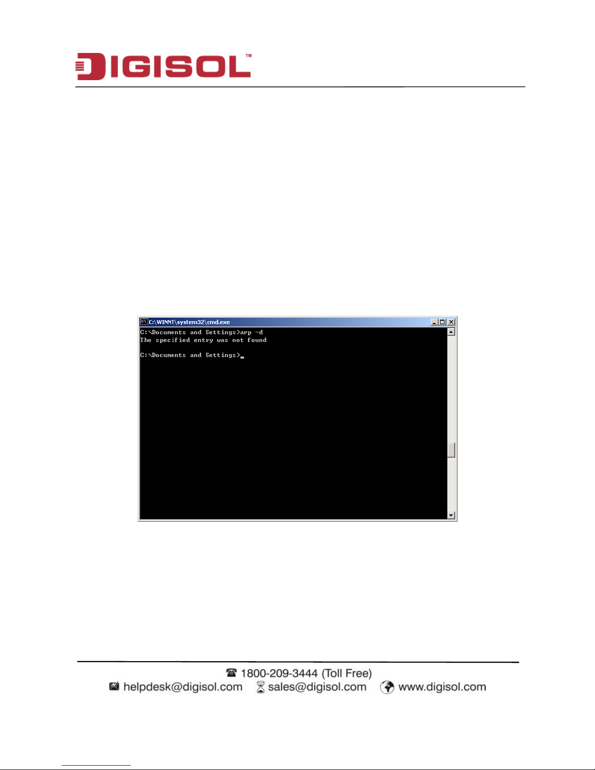
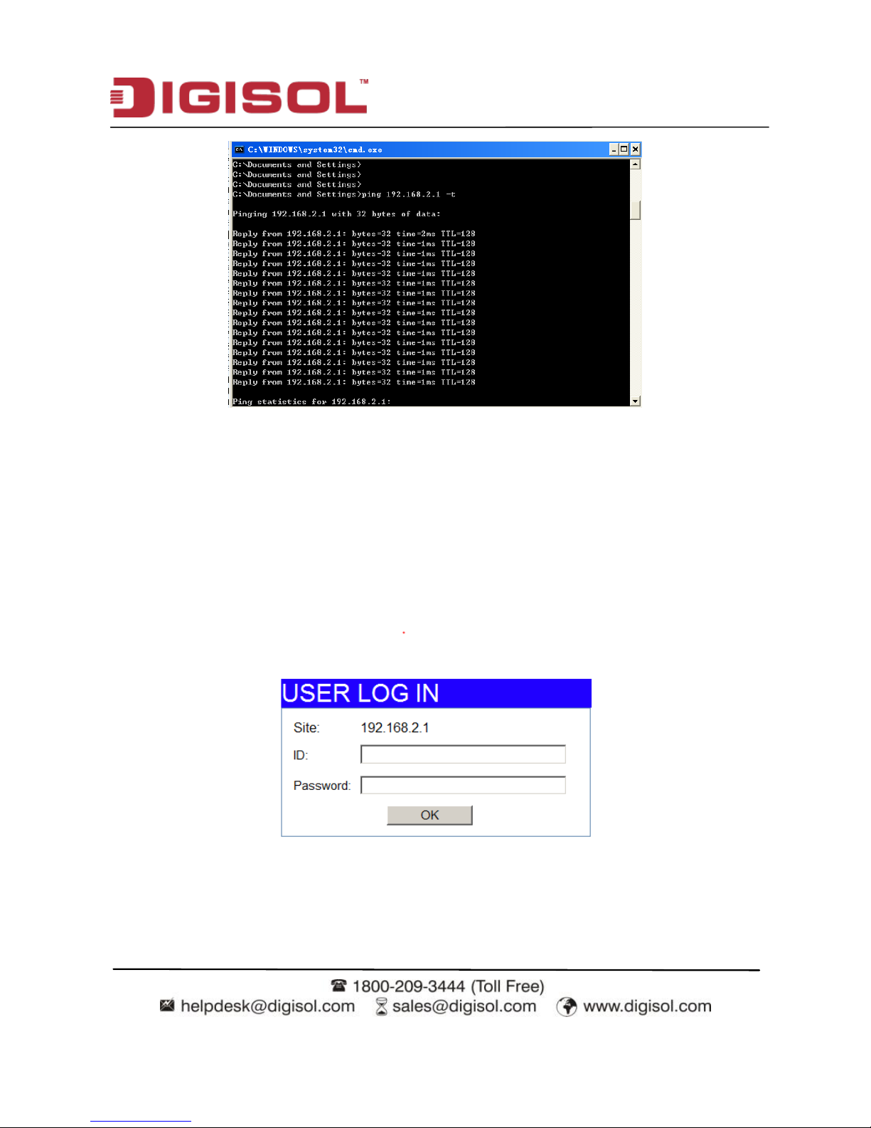
7.1 Preparation Before Login
Before accessing the switch, ensure the communication between PC and switch is normal.
Check the communication as follows.
1. Set the IP address of the PC in the range 192.168.2.X (2~254)
2. The subnet mask to 255.255.255.0.
3. Enter arp -d or arp -d 192.168.2.1 in the DOS window. See the following figure.
1. Ping the maintenance IP address (192.168.2.1 by default) of the switch. See the
following figure.
Page 16
DG-FS1510HPE User Manual
16
If the PC can read the MAC address of the switch and can ping through the maintenance IP
address of the switch, that means the communication of the PC and the switch is normal.
7.2 Logging In to the Switch
1. Open the web browser, and type the default IP address of switch in the address bar
as ‗http: //192.168.2.1‘.
2. Enter the ID and the password. The default ID is admin and password is system.
3. Click OK to log in.
Page 17
DG-FS1510HPE User Manual
17
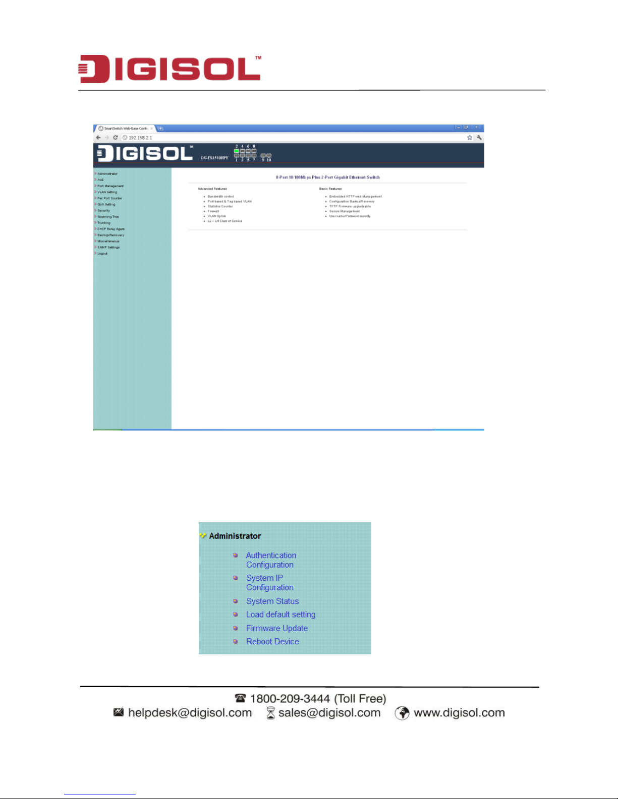
After logging in to the switch successfully, the following page appears.
7.3 System Management
Choose Administrator, and the sub-menus of Administrator are shown as below.
Page 18
DG-FS1510HPE User Manual
18
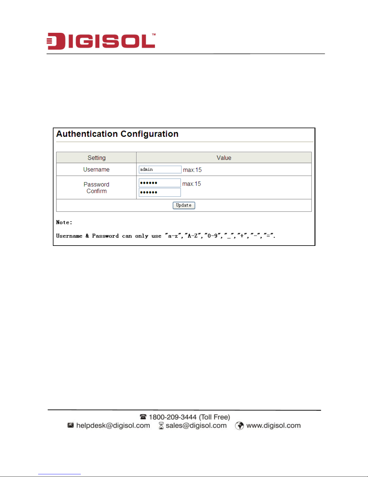
7.3.1 Authentication Configuration
Choose Administrator > Authentication Configuration, and the following page appears.
Read the Note in the page, and change the user name and password. After proper
configuration, click Update to apply the settings and then Reboot the device for the
changes to take effect.
Page 19

DG-FS1510HPE User Manual
19
7.3.2 System IP Configuration
Choose Administrator > System IP Configuration, and the following page appears. In this
page, you can set the maintenance IP address of the switch, subnet mask and gateway. After
proper configuration, click Update to apply the settings and then Reboot the device for the
changes to take effect.
Page 20

DG-FS1510HPE User Manual
20
7.3.3 System Status
Choose Administrator > System Status, and the following page appears. In this page,
you can view the MAC address, Number of ports, Comment,system version and idle time
security.
7.3.4 Loading Default Settings
Choose Administrator > Load default setting and the following page appears. In this
page, click Load to load the default settings that do not include IP address, user name and
password.
Page 21

DG-FS1510HPE User Manual
21
7.3.5 Firmware Update
Choose Administrator > Firmware Update, and the following page appears. In this page,
enter the login password and reenter the password in Reconfirm field. Then click Update.
A pop up page will appear asking you to select new file for updating the firmware.
Caution:
When firmware update is in progress, do not shut down the switch.
7.3.6 Reboot the Device
Choose Administrator > Reboot Device, and the following page appears. In this page,
click Confirm to reboot the device.
Page 22

DG-FS1510HPE User Manual
22
7.4 POE
Choose POE, and the submenus of POE are shown as below.
7.4.1 PoE Status
Choose PoE> PoE Status and the following page appears displaying: Max available
Power, System operation status, Main power consumption, device temperature etc.
Page 23

DG-FS1510HPE User Manual
23
7.4.2 PoE Setting
Choose PoE > PoE Setting and the following page appears.
Page 24

DG-FS1510HPE User Manual
24
7.4.3 PoE Power Delay
Choose PoE > PoE Power Delay and the following page appears.
Page 25

DG-FS1510HPE User Manual
25
7.4.4 PoE Scheduling
Choose PoE > PoE Scheduling and the following page appears. Here you can schedule
on which day and time the PoE ports will be disabled.
7.4.5 NTP Setting
Choose PoE > NTP Setting and the following page appears. Set the NTP server 1 and 2.
Choose the time zone from which area you are from the drop down list.
Page 26

DG-FS1510HPE User Manual
26
7.5 Port Management
Choose Port Management, and the submenus of Port Management are shown as below.
7.5.1 Port Configuration
Choose Port Management > Port Configuration, and the following page appears. In this
page, you can set Tx/Rx Ability, Auto-Negotiation, Speed, Duplex, Pause,
Backpressure and Addr. Learning of port.
Page 27

DG-FS1510HPE User Manual
27
7.5.2 Port Mirroring
Choose Port Management > Port Mirroring, and the following page appears. In this
page, you can enable port mirroring service. The packets from source port transmit to
destination port.
Page 28

DG-FS1510HPE User Manual
28
7.5.3 Bandwidth Control
Choose Port Management > Bandwidth Control and the following page appears.
After proper configuration, click Update to apply the settings. Click Load Default to
restore the default settings.
Page 29

DG-FS1510HPE User Manual
29
7.5.4 Broadcast Storm Control
Choose Port Management > Broadcast Storm Control and the following page appears.
7.6 VLAN Setting
In large networks, routers are used to isolate broadcast traffic for each subnet into separate
domains. This switch provides a similar service at Layer 2 by using VLANs to organize
any group of network nodes into separate broadcast domains. VLANs confine broadcast
traffic to the originating group, and can eliminate broadcast storms in large networks. This
also provides a more secure and cleaner network environment.
The system supports VLAN based on port and VLAN based on tag. You can change the
VLAN mode in the VLAN Mode page.
Choose VLAN Setting, and the sub-menus of VLAN Setting are shown as below.
Page 30

DG-FS1510HPE User Manual
30
7.6.1 VLAN Mode
7.6.1.1 VLAN Based on Port
Choose VLAN Setting > VLAN Mode, and the following page appears. The default mode
is Port Based VLAN. Click Change VLAN mode to change the VLAN mode.
Once "Change VLAN mode" is selected, a warning message will appear. Select "Continue"
to change the mode or select "Back" to keep the existing vlan mode.
7.6.2 VLAN Member
7.6.2.1 VLAN Based on Port
Choose VLAN Setting > VLAN Member, and the following page appears.
Page 31

DG-FS1510HPE User Manual
31
7.6.2.2 VLAN Based on Tag
When the VLAN mode is tag based, the VLAN Member Setting page is shown as the
following figure.
Field
Description
VID
Select the Vlan ID to be assigned to the VLAN and click on Add to
enter the VID. Once the VID is added it will appear in the drop down
list.
VLAN Member Port
Select the VID from the Dropdown list and then select the desired
member ports from the Table.
Port VID MAP
Port VID map shows the Port number corresponding to the VID to
which the same is assigned.
Page 32

DG-FS1510HPE User Manual
32
When the port receives the packets without tag, the system can check the VLAN table
according to the port VID. The system can add the tag according to the VID found in the
VLAN table.
To add vlan, enter a VID and select vlan member for this entry from vlan member list. Now
select ―Add‖ button to add vlan entry to the table. Vlan entry can be modified by selecting
VID from the list and then select ―Update‖ button.
To delete an entry from the vlan table, select VID from the drop-down list and select ―Delete‖
to remove the corresponding entry from the table.
Page 33

DG-FS1510HPE User Manual
33
7.6.3 Multi to 1 Setting Configuration
Choose VLAN Setting > Multi to 1 setting, and the following page appears. This feature
can disable communication between ports in order to improve the security.
After setting the multi to 1 setting, the VLAN original setting will be cleared.
If the VLAN is configured again, the multi to 1 setting will be cleared.
Multi to 1 Settings take effect only when ―VLAN based on port‖ mode is
selected.
In this page, select the current port from the drop-down list. Then select the port from the
check box to isolate from the current port.
Page 34

DG-FS1510HPE User Manual
34
7.7 Per Port Counter
Choose Per Port Counter, and the Port Counter submenu is shown as below.
Choose Per Port Counter > Port Counter and the following page appears. In this page,
you can view the packet quantity.
Page 35

DG-FS1510HPE User Manual
35
7.8 QoS Configuration
All switches or routers that access the Internet, rely on class information to provide the same
forwarding treatment to packets in the same class. Class information can be assigned by end
hosts, or switches or routers along the path. Priority can then be assigned based on a general
policy, or a detailed examination of the packet. However, note that detailed examination of
packets should take place close to the network edge so that core switches and routers are not
overloaded.
Switches and routers along the path can use class information to prioritize the resources
allocated to different traffic classes. The manner in which an individual device handles traffic
is called per-hop behavior. All devices along a path should be configured in a consistent
manner to construct a consistent end-to-end Quality of Service (QoS) solution.
Choose QoS Setting, and the sub-menus of QoS Setting are shown as below.
Field
Description
Counter Mode
Selection
Select it from the drop-down list:
Click Update to view the corresponding packet quantity.
Refresh
Click the button to refresh the counter information.
Clear
Click the button to clear the counter information.
Page 36

DG-FS1510HPE User Manual
36
7.8.1 Priority Mode
Choose QoS Setting > Priority Mode, and the following page appears. In this page, you
can set the priority mode.
The system supports the following three priority modes.
First-In-First-Out
All-High-before-Low
Weight-Round-Robin
Low weight: You can select 0 ~ 7 from the drop-down list.
High weight: You can select 0 ~ 7 from the drop-down list.
Page 37

DG-FS1510HPE User Manual
37
7.8.2 Class of Service Configuration - 1
Choose QoS Setting > Port, 802.1p, IP/DS based, and the following page appears.
The COS of port supports the following mode.
Based on port
Based on 802.1p: The priority is determined according to the value of
802.1p (bit [15:13]) in the VLAN Tag. Packets in which values of
802.1p (bit [15:13]) are 000-011 map to lower priority. Packets in which
values of 802.1p (bit [15:13]) are 100-111 map to higher priority.
Based on IP / DS:
For IPv4 packets, the priority is determined according to the value of
TOS [5:0] in the header. Packets in which values of TOS [5:0] are
101110, 001010, 010010, 011010 and 11x000 map to higher priority.
Packets in which TOS [5:0] are other values map to lower priority.
Page 38

DG-FS1510HPE User Manual
38
7.8.3 Class of Service Configuration - 2
Choose QoS Setting > TCP/UDP Port Based and the following page appears. COS based
on TCP/UDP port specifies the priority queues of packets or discards designated protocol
packets according to the application layer protocols of packets received at the port. COS
supports classifying packets into corresponding priority queues or discards packets
according to the port in the range of ports 1-65535, besides certain known protocols, such
as FTP, telnet and SNMP.
Page 39

DG-FS1510HPE User Manual
39
Field
Description
Option
You can select it from the drop-down list:
User_Define
Port: The valid range is 1 ~ 65535.
Mask: The valid range is 0 ~ 255.
TCP/UDP port QoS
function
Override: When the "override" item is selected, the
Port_based, Tag based, IP TOS_based, CoS listed
previous will be ignored.
Not Override
Page 40

DG-FS1510HPE User Manual
40
7.9 Security
Choose Security, and the sub-menus of Security are shown as below.
7.9.1 MAC Address Binding
Choose Security > MAC Address Binding and the following page appears. After MAC
address binding is enabled at a port, only devices whose MAC addresses are consistent
with the bound MAC address can communicate through the port. A port can be bound to a
maximum of three MAC addresses.
If MAC address binding is enabled, address learning is automatically disabled and
RSTP/STP is affected. It is recommended to disable STP on the port.
Page 41

DG-FS1510HPE User Manual
41
The configuration procedure:
Step 1 Enter the MAC address.
Step 2 Select the port that you want to bind MAC address.
Step 3 Select Enable from the drop-down list to enable the binding service.
Step 4 Click Update to apply the service of MAC address binding.
7.9.2 TCP/UDP Filter
Choose Security > TCP/UDP Filter and the following page appears. TCP/UDP port filter
discards the set protocol packets at the secure WAN port. All ports can be set to secure
WAN ports, and the available protocols include FTP, HTTP and TELNET.
Page 42

DG-FS1510HPE User Manual
42
The configuration procedure:
1. Select Enable from the drop-down list to enable the TCP/UDP filter service.
2. Select port filtering rule. Negative means the selected protocol will be dropped and
other protocols will be forwarded. Positive means the selected protocol will be
forwarded and other protocol will be dropped.
3. Select the protocol from the check box in the right area.
4. Select the secure WAN port.
5. Click Update to apply the settings.
7.10 Spanning Tree
Choose Spanning Tree, and the sub-menus of Spanning Tree are shown as below.
Page 43

DG-FS1510HPE User Manual
43
7.10.1 STP Bridge Settings
Choose Spanning Tree > STP Bridge Settings, and the following page appears.
Field
Description
STP Mode
You can select it from the drop-down list:
Page 44

DG-FS1510HPE User Manual
44
Field
Description
Bridge Priority
The valid range is 0 ~ 61440. The lower integer value for
precedence indicates the higher priority and the integer should
be a multiple of 4096.
Hello Time
The valid range is 1 ~ 10. The unit is seconds. The hello time
indicates the interval of transmitting BPDU.
Max Age
The valid range is 6 ~ 40. The unit is seconds. It is the longest
waiting time of the blocking state turning into listening state.
Max Age >= 2*(Hello Time+1)
Forward Delay
The valid range is 4 ~ 30. The unit is seconds. It is the longest
waiting time of the listening state turning into learning state or
the learning state turning into forwarding state.
2*(Forward Delay-1) >= Max Age
After proper configuration, click Submit to apply the settings. In the mean time, you can
view the STP bridge status.
Page 45

DG-FS1510HPE User Manual
45
7.10.2 STP Port Settings
Choose Spanning Tree > STP Port Settings, and the following page appears.
Field
Description
Port No.
Select it from the drop-down list.
RPC
Root Path Cost. The valid range is 1 ~ 200000000.
0 indicates Auto.
Priority
The valid range is 0 ~ 240. It should be a multiple of 16.
Page 46

DG-FS1510HPE User Manual
46
RPC determines the path cost that is from per port to root bridge. It is related with speed. The
following table lists the recommended value. You can modify it during actual using.
Speed
IEEE Recommended Value
Recommended Range
10Mbps
100
50~600
100Mbps
19
10~60
1000Mbps 4 3~10
10GMbps 2 1~5
After proper configuration, click Submit to apply the settings. In the mean time, you can
view the STP port status.
Page 47

DG-FS1510HPE User Manual
47
7.10.3 Loopback Detection:
Choose Spanning Tree > Loopback Detection to configure loopback detection on an
interface. When loopback detection is enabled and a port receives it‘s own BPDU, the
detection agent drops the loopback BPDU and places the interface in discarding mode. This
loopback state can be released automatically.
Page 48

DG-FS1510HPE User Manual
48
These parameters are displayed:
Field
Description
Loopback Detection Function
Enables/Disables (Default: disable)
Auto Wake Up
Configures the interface for automatic loopback release.
Wake-Up Time interval
Defines the time interval for the port that will be released
from the discarding state.
Interface status displays a list of ports with loopback detection status. Select ―Reset All Ports‖
option for manual release.
Page 49

DG-FS1510HPE User Manual
49
7.11 Trunking
This section describes how to configure static and dynamic trunks.
You can create multiple links between devices that work as one virtual aggregate link. A port
trunk offers a dramatic increase in bandwidth for network segments where bottlenecks exist,
as well as providing a fault tolerant link between two devices.
The switch supports both static trunking and dynamic Link Aggregation Control Protocol
(LACP). Static trunks have to be manually configured at both ends of the link. On the other
hand, LACP configured ports can automatically negotiate a trunked link with
LACP-configured ports on another device.
Choose Trunking, and the Link Aggregation Settings sub-menu is shown as below.
Choose Trunking > Link Aggregation Settings, and the following page appears.
Page 50

DG-FS1510HPE User Manual
50
Field
Description
System Priority
The valid range is 1 ~ 65535.
Link Aggregation
Algorithm
You can select it from the drop-down list:
Member
The system supports three link groups.
Link Group 1: It includes the following ports: 1, 2, 3, 4.
Link Group 2: It includes the following ports: 5, 6, 7, 8.
Link Group 3: It includes the following ports: 9, 10.
State
You can select Disable or Enable.
Type
You can select it from the drop-down list:
Operation Key
When the type is LACP, there are some protocol parameters. Such
as operation key, transmitting LACP packets interactively or not.
Time Out
You can select it from the drop-down list:
It is the time out of trunking, when the link port does not receive
the corresponding LACPDU.
Activity
You can select it from the drop-down list:
One switch should be set to Active between two switches.
Page 51

DG-FS1510HPE User Manual
51
After proper configuration, click Submit to apply the settings. Click Refresh to refresh the
state of link group. When the ―--‖ in Member configuration turns into ―A‖, that indicates the
trunking service has established between the system and the corresponding end.
7.12 DHCP Relay Agent
Choose DHCP Relay Agent and the submenu shown as below appears.
7.12.1 DHCP Relay Agent
Field
Description
DHCP relay State
Select Enable or Disable to start or Stop the DHCP relay agent
respectively.
Note: When you configure trunking service, you need to disable the Pause
and Backpressure of corresponding port in the Port Configuration page in the
Port management navigation.
Page 52

DG-FS1510HPE User Manual
52
DHCP relay Hop
count limit
Sets the maximum allowed number in the hops field of the
BOOTP/DHCP header.
DHCP relay option
82 State
Select Enable or Disable to start or Stop the DHCP relay option 82
respectively.
7.12.2 Relay Server
Choose Relay Server and the following page appears.
7.12.3 VLAN MAP Relay Agent
Choose VLAN MAP Relay Agent
After proper configuration, click Submit to apply the settings. Click Refresh to refresh
the state of link group.
Page 53

DG-FS1510HPE User Manual
53
7.13 Configuration Backup and Recovery
Choose Backup/Recovery, and the following page appears. In this page, you can download
the switch configuration to PC, or upload the configuration file to switch according to the
page attention.
Page 54

DG-FS1510HPE User Manual
54
7.14 Miscellaneous Configuration
Choose Miscellaneous, and the following page appears. In this page, you can enable
Aging, VLAN striding and set VLAN uplink.
Page 55

DG-FS1510HPE User Manual
55
7.15 SNMP Settings
Choose SNMP Settings, and the following page appears. In this page, you can configure
SNMP related parameters.
Field
Description
Community Name.
The community name used by SNMP.
Access Right
The right of community name.
System Description
System Contact
System Location
System related information.
Trap State
Enable/disable SNMP trap.
Page 56

DG-FS1510HPE User Manual
56
7.16 Logout
Choose Logout, and the following page appears.
In this page, the system asks you whether to logout. Click Accept to logout. Click Back to
return to the previous page.
8 Troubleshooting
If a fault occurs, refer to the following table for troubleshooting:
Symptom
Suggested Solution
The Power indicator is not
ON after the system has
started
Check whether the power is correctly connected.
Check whether the power switch is turned on.
The Power indicator is
ON but the Ethernet
indicator is off
Check whether the network cable is correctly
connected.
Check whether the configuration is correct.
Page 57

DG-FS1510HPE User Manual
57
9 Glossary
Auto-negotiation: Auto-negotiation is an Ethernet procedure by which two connected
devices choose common transmission parameters, such as speed, duplex mode and flow
control. In this process, the connected devices first share their capabilities as for these
parameters and then choose the highest performance transmission mode they both support.
Backpressure: The build-up of data behind an I/O switch if the buffers are full and
incapable of receiving any more data; the transmitting device halts the sending of data
packets until the buffers have been emptied and are once more capable of storing
information.
Flow-control: Flow control is the process of managing the pacing of data transmission
between two nodes to prevent a fast sender from outrunning a slow receiver. It provides a
mechanism for the receiver to control the transmission speed, so that the receiving node is not
overwhelmed with data from transmitting node.
Address Learning: Address learning is a service that characterizes a learning bridge, in
which the source MAC address of each received packet is stored so that future packets
destined for that address can be forwarded only to the bridge interface on which that address
is located.
TCP: The Transmission Control Protocol (TCP) is one of the core protocols of the Internet
Protocol Suite. TCP is one of the two original components of the suite, complementing the
Internet Protocol (IP), and therefore the entire suite is commonly referred to as TCP/IP. TCP
provides reliable, ordered delivery of a stream of bytes from a program on one computer to
another program on another computer.
UDP: User Datagram Protocol. UDP provides a datagram mode for packet-switched
communications. It uses IP as the underlying transport mechanism to provide access to
IP-like services. UDP packets are delivered just like IP packets – connection-less datagrams
that may be discarded before reaching their targets. UDP is useful when TCP would be too
complex, too slow, or just unnecessary.
Page 58

DG-FS1510HPE User Manual
58
FTP: File Transfer Protocol (FTP) is a standard network protocol used to copy a file from
one host to another over a TCP-based network, such as the Internet. FTP is built on
client-server architecture and utilizes separate control and data connections between the client
and server.
Http: The Hypertext Transfer Protocol (HTTP) is a networking protocol for distributed,
collaborative, hypermedia information systems.
TELNET: Telnet defines a remote communication facility for interfacing to a terminal
device over TCP/IP.
ToS: Type of Service level, which processes the precedence part of the IP packet ToS (3
bits) as an index to the eight QoS Class values.
Link-Aggregation: Link aggregation is a term which describes using multiple network
cables/ports in parallel to increase the link speed beyond the limits of any one single cable or
port, and to increase the redundancy for higher availability.
COS: Class of Service is supported by prioritizing packets based on the required level of
service, and then placing them in the appropriate output queue. Data is transmitted from the
queues using weighted round-robin service to enforce priority service and prevent blockage
of lower-level queues. Priority may be set according to the port default, the packet‘s priority
bit
(in the VLAN tag), TCP/UDP port number, IP Precedence bit, or DSCP priority bit.
SNMP: Simple Network Management Protocol. The application protocol in the Internet
suite of protocols which offers network management services.
QOS: Quality of Service. QoS refers to the capability of a network to provide better service
to selected traffic flows using features such as data prioritization, queuing, congestion
avoidance and traffic shaping. These features effectively provide preferential treatment to
specific flows either by raising the priority of one flow or limiting the priority of another
flow.
Page 59

DG-FS1510HPE User Manual
59
DHCP: Dynamic Host Control Protocol. Provides a framework for passing configuration
information to hosts on a TCP/IP network. DHCP is based on the Bootstrap Protocol
(BOOTP), adding the capability of automatic
allocation of reusable network addresses and additional configuration options.
DHCP OPTION 82: A relay option for sending information about the requesting client
(or an intermediate relay agent) in the DHCP request packets forwarded by the switch and in
reply packets sent back from the DHCP server. This
information can be used by DHCP servers to assign fixed IP addresses, or set other services
or policies for clients.
This product comes with Three Years warranty. For further details about
warranty policy and Product Registration, please visit support section of
www.smartlink.co.in
 Loading...