

Page 1
DG-BR4000N/E
150Mbps Wireless Broadband Router
User Manual
V1.0
2012-08-22
As our products undergo continuous development the specifications are subject to change without prior notice
Page 2

DG-BR4000N/E User Manual
COPYRIGHT
Copyright © 2012 by this company. All rights reserved. No part of this publication may be
reproduced, transmitted, transcribed, stored in a retrieval system, or translated into any language or
computer language, in any form or by any means, electronic, mechanical, magnetic, optical,
chemical, manual or otherwise, without the prior written permission of this company
This company makes no representations or warranties, either expressed or implied, with respect to
the contents hereof and specifically disclaims any warranties, merchantability or fitness for any
particular purpose. Any software described in this manual is sold or licensed "as is". Should the
programs prove defective following their purchase, the buyer (and not this company, its distributor,
or its dealer) assumes the entire cost of all necessary servicing, repair, and any incidental or
consequential damages resulting from any defect in the software. Further, this company reserves the
right to revise this publication and to make changes from time to time in the contents thereof
without obligation to notify any person of such revision or changes.
Trademarks:
DIGISOL™ is a trademark of Smartlink Network Systems Ltd. All other trademarks are the
property of the respective manufacturers.
Safety
This equipment is designed with the utmost care for the safety of those who install and use it.
However, special attention must be paid to the dangers of electric shock and static electricity when
working with electrical equipment. All guidelines of this and of the computer manufacturer must
therefore be allowed at all times to ensure the safe use of the equipment.
2
Page 3

DG-BR4000N/E User Manual
Index
1. Product Information ................................................................................................. 5
1-1 Introduction and Safety Information ............................................................ 5
1-2 Safety Information ....................................................................................... 7
1-3 System Requirements ................................................................................. 8
1-4 Package Contents ....................................................................................... 8
1-5 Get familiar with your new wireless broadband router ................................ 9
2. Connecting the Device .......................................................................................... 12
2-1 Operation Range ....................................................................................... 12
2-2 Roaming .................................................................................................... 13
2-3 TCP/IP Settings and Wireless Connection Introduction ............................ 14
2-4 Wireless Connection.................................................................................. 19
3. Software Installation .............................................................................................. 22
4. Logging In to the Web Page.................................................................................. 35
4-1 Web Configuration ..................................................................................... 36
4-2 Running Status .......................................................................................... 40
4-3 Router Status ............................................................................................. 41
4-4 Clients List ................................................................................................. 45
4-5 Network Settings ....................................................................................... 45
4-6 LAN Interface Settings .............................................................................. 46
4-7 WAN Interface Settings ............................................................................. 49
5. Wireless Settings .................................................................................................. 57
5-1 Wireless Basic Settings ............................................................................. 57
5-2 Guest Network ........................................................................................... 62
5-3 WPS Setup ................................................................................................ 64
5-4 Wireless Advanced Settings ...................................................................... 66
5-5 Wireless Repeater ..................................................................................... 70
6. Forwarding Rule .................................................................................................... 72
6-1 Port Forwarding ......................................................................................... 72
6-2 Port Triggering ........................................................................................... 74
6-3 UPnP ......................................................................................................... 77
3
Page 4

DG-BR4000N/E User Manual
7. Access Control ...................................................................................................... 79
7-1 Block Sites ................................................................................................. 79
7-2 Block Services ........................................................................................... 82
7-3 QoS Setup ................................................................................................. 84
8. Dynamic DNS ........................................................................................................ 91
9. Static Routing ........................................................................................................ 92
10. Security Options .................................................................................................. 94
10-1 Remote Management .............................................................................. 94
10-2 WAN Setup .............................................................................................. 96
11. System Tools ...................................................................................................... 98
11-1 Schedules ................................................................................................ 98
11-2 SNTP ....................................................................................................... 99
11-3 Backup Settings ..................................................................................... 101
11-4 Set Password ......................................................................................... 102
11-5 Router Upgrade ..................................................................................... 104
12. Logout ............................................................................................................... 105
13. Appendix ........................................................................................................... 106
13-1 Hardware Specifications ........................................................................ 106
14. Troubleshooting ................................................................................................ 108
15. Glossary ............................................................................................................ 110
4
Page 5

DG-BR4000N/E User Manual
1. Product Information
1-1 Introduction and Safety Information
Thank you for purchasing DG-BR4000N/E 802.11n 150Mbps Wireless Broadband Router.
DG-BR4000N/E is the best choice for Small office / Home office users, all computers and
network devices can share a single xDSL / cable modem internet connection at high speed.
Easy install procedures allow any computer users to setup a network environment in very short
time - within minutes, even inexperienced. When the number of your computers and
network-enabled devices grow, you can also expand the number of network slots by
connecting a hub or switch, to extend the scope of your network.
All computers and IEEE 802.11b/g/n wireless-enabled network devices (including PDA, cellular
phone, game console, and more) can connect to this wireless router without additional cabling.
With a compatible wireless card installed in your PC, you can transfer files up to 150Mbps
(transfer data rate).
Other features of this Wireless USB adapter include:
• Supports IEEE802.11b, IEEE802.11g, IEEE802.11n, IEEE802.3, IEEE802.3u,
IEEE802.11i and IEEE802.11e.
• Transmission data rate is up to 150 Mbps.
• Supports WEP and WPA for secured data transmission.
• Supports DHCP server.
• Supports manual configuration of static routing.
• Supports version upgrade through Web page.
• Supports restoring the factory default settings.
• Supports demilitarized zone (DMZ).
• Supports DNS proxy and forwarding.
• Supports QoS.
• Supports UPnP.
5
Page 6

DG-BR4000N/E User Manual
• Supports WPS.
• Supports port mapping.
• Supports port triggering.
• Supports wireless repeater.
• Supports guest network.
• Supports restricting IP bandwidth.
• Supports filtering by keyword and domain name.
• Supports wireless security authentication.
• Supports 3 types of WAN connection modes, including static IP, dynamic IP and PPPoE.
• Supports remote access control.
• Supports firewall.
• Supports system status display.
• Supports backup and restoration of configuration file.
6
Page 7

DG-BR4000N/E User Manual
1-2 Safety Information
Before operating the wireless router, read the following safety information carefully:
• Use the power adapter that is packed within the device package. DO NOT use any other
power adapter or it will damage the product.
• Pay attention to the power load of the outlet or the prolonged lines. An overburdened
power outlet or damaged lines and plugs may cause electric shock or fire accident.
Check the power cords regularly. If you find any damage, replace it at once.
• Proper space left for heat dissipation is necessary to avoid any damage caused by
overheating the device. The long and thin holes on the router are designed for heat
dissipation, to ensure that the device works normally. DO NOT cover these cooling holes.
• DO NOT put this device close to a place where a heat source exists or high temperature
occurs. Avoid exposing the device to direct sunlight.
• DO NOT place this device close to a place which is over damp or watery.
• DO NOT spill any liquid on this device.
• DO NOT connect this device to any PC or electronic product, unless our customer,
engineer or your broadband provider instructs you to do this, because any wrong
connection may cause any power or fire risk.
• DO NOT place this device on an unstable surface or support.
• When the device is connected to a computer, hub, router or switch, the Ethernet cable
should be less than 100 meters.
• DO NOT place this device on an unstable surface or support. DO NOT place this device
on the ground.
• Keep the device clean. Avoid any metal in the device.
• Place the device in the center of the area, and try to optimize the wireless coverage.
7
Page 8

DG-BR4000N/E User Manual
1-3 System Requirements
•
A desktop computer with a network adapter (wired / WLAN). The PC should be installed
with the TCP/IP protocol and should be able to access internet.
• Windows 2000/XP/Vista or Windows 7.
• Web Browser (Microsoft Internet Explorer 6.0 or above, Mozilla Firefox, Opera web
browser, or Safari web browser).
• AC Power socket (100-240V 50 / 60 Hz)
1-4 Package Contents
Before you start using this wireless broadband router, please check if there’s anything missing in
the package, and contact your dealer of purchase to claim for missing items:
• Wireless Broadband router
• Power adapter (12V DC, 500mA)
• Quick Installation Guide
• Installation Guide CD (includes User manual, QIG & Utility)
• Patch Cord (1No.)
8
Page 9

DG-BR4000N/E User Manual
1-5 Get familiar with your new wireless broadband router
Top Panel
There are 8 LED indicators on the front panel of the wireless router. By observing their status,
you can check whether the device runs normally.
9
Page 10

DG-BR4000N/E User Manual
On
Green
Power is on.
On
Green
Radio switch is turned on.
Off - Radio switch is shut off.
Setup.
Protected Setup.
On
Connection succeeds.
Off
No WAN connection.
On
LAN connection succeeds.
Blink
Data is being transmitted.
The following table describes the status of LED indicators on the front panel.
LED
Name
Light
Status
LED
Color
Description
Power
WLAN
WPS
WAN
LAN1/LAN2/
LAN3/LAN4
Off - Power is off or the device is down.
Blink Green Data is being transmitted.
On Green
Blink Green
Off - Wi-Fi Protected Setup is disabled.
Blink Data is being transmitted.
Off No LAN connection.
Green
Green
Connection succeeds under Wi-Fi Protected
Negotiation is in progress under Wi-Fi
10
Page 11

DG-BR4000N/E User Manual
factory defaults.
Power
Power socket, for connecting the power adapter.
devices.
LAN3/LAN4
LAN.
negotiation of PBC mode.
Rear Panel
The following table describes interfaces and buttons on the rear panel.
Interface/Button Description
Use a fine needle to press the Reset button gently until the unit
Reset
reboots and then release the button. The unit reboots and restores to
WAN
LAN1/LAN2/
WPS
RJ45 WAN interface, for connecting WAN or the uplink network
RJ45 LAN interfaces, for connecting hub, switch or computer in a
This button is used for enabling WPS PBC mode.
When WPS is enabled, press this button, and the AP starts accepting
11
Page 12
DG-BR4000N/E User Manual
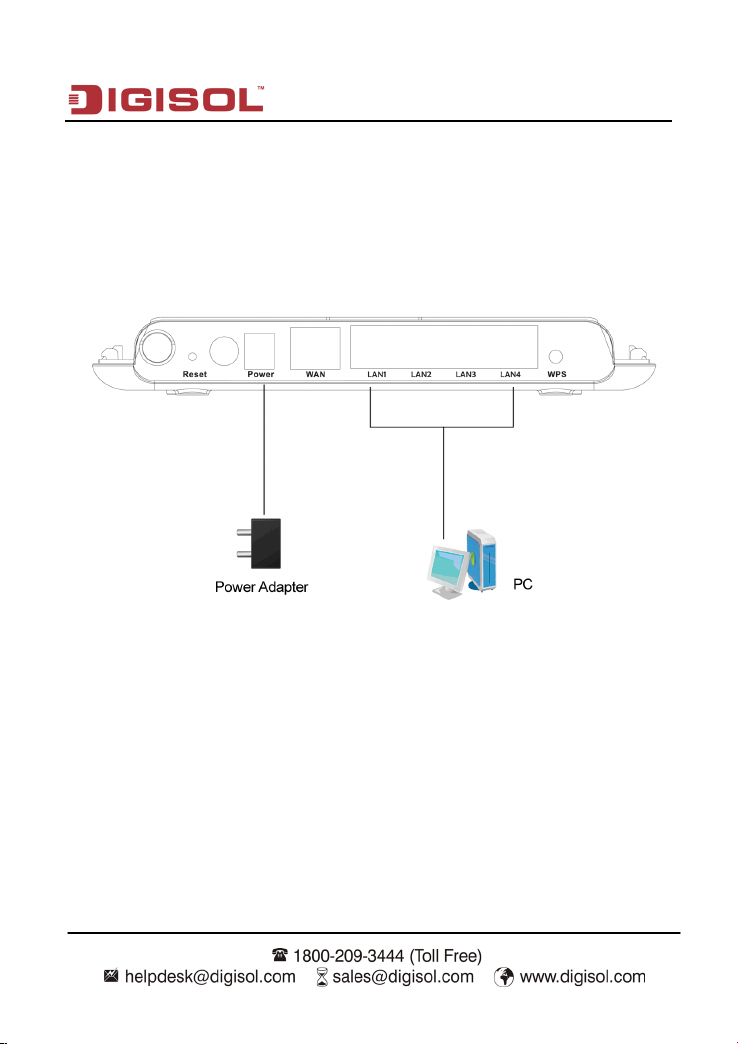
2. Connecting the Device
To connect the device, do as follows:
Step 1 Connect one end of the RJ45 cable to the LAN interface of the wireless router.
Step 2 Connect the other end of the RJ45 cable to your PC.
Step 3 Connect the power adapter to the power socket of the wireless router.
2-1 Operation Range
The operation range of the wireless router depends on the actual environment. The path and
effect of signal transmission varies according to the deployment when in a house or an office. For
example, the outdoor straight transmission distance for a certain device can be 300 meters and
the indoor transmission distance can be 100 meters.
12
Page 13

DG-BR4000N/E User Manual
2-2 Roaming
Suppose several wireless routers run in the same network. Each wireless router serves as a
BSS that has its coverage range. One wireless client (for example, a notebook PC or PDA) can
roam from one AP to another AP accurately. In that case, the wireless client can communicate
with the other devices within the coverage range of the wireless router.
For roaming in the coverage range of the wireless router by a wireless client, you need to set
the APs properly as follows:
• Set the same SSID for different APs.
• The SSIDs of all the computers and PDAs should be consistent with that of APs.
• All the BSSs must use the same wireless channel.
• If the encryption function is enabled, all wireless routers must be configured with the
same encryption mode and encryption key for establishing connection.
• Wireless routers must keep coverage of uninterrupted wireless signals in the whole
operation environment. Hence, please place wireless routers at appropriate places.
13
Page 14
DG-BR4000N/E User Manual
2-3 TCP/IP Settings and Wireless Connection Introduction
By default, the LAN IP address of the wireless router is 192.168.2.1, the subnet mask is
255.255.255.0 and the DHCP server is enabled.
It is recommended to set the network adapter to obtain an IP address automatically. Then, your
PC obtains the TCP/IP settings, including the IP address, subnet mask, gateway and DNS
address automatically through the wireless router. If you know the settings of the current LAN
interface, you can manually set the TCP/IP properties of the network adapter, so that your PC
can communicate with the wireless router.
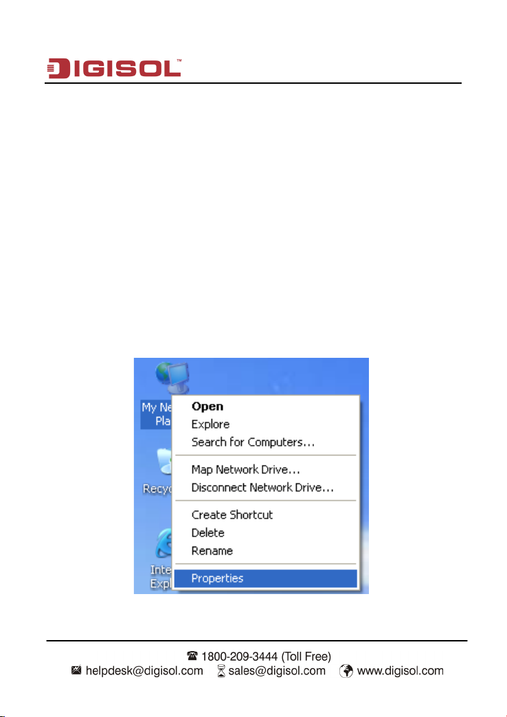
To manually set the network adapter, do as follows:
Step 1 Right-click the icon of My Network Places and choose Properties from the menu.
The Network Connections window appears.
14
Page 15
DG-BR4000N/E User Manual
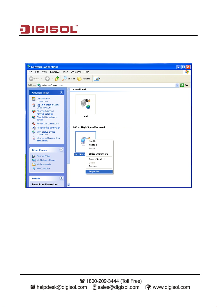
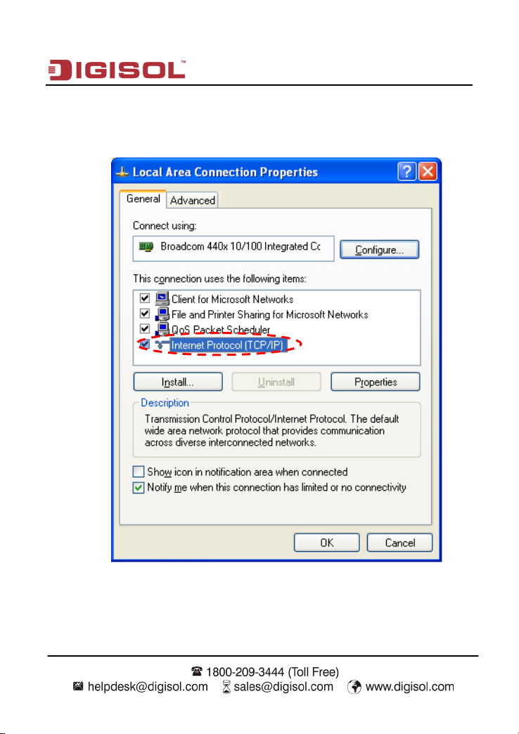
Step 2 Right-click the network adapter icon and choose Properties from the menu. The
Local Area Connections Properties window appears.
Note: If multiple network cards are installed on your PC, a window other than
the Local Area Connection Properties window may appear.
15
Page 16
DG-BR4000N/E User Manual
Step 3 Double-click Internet Protocol (TCP/IP) and the Internet Protocol (TCP/IP)
Properties window appears.
16
Page 17
DG-BR4000N/E User Manual
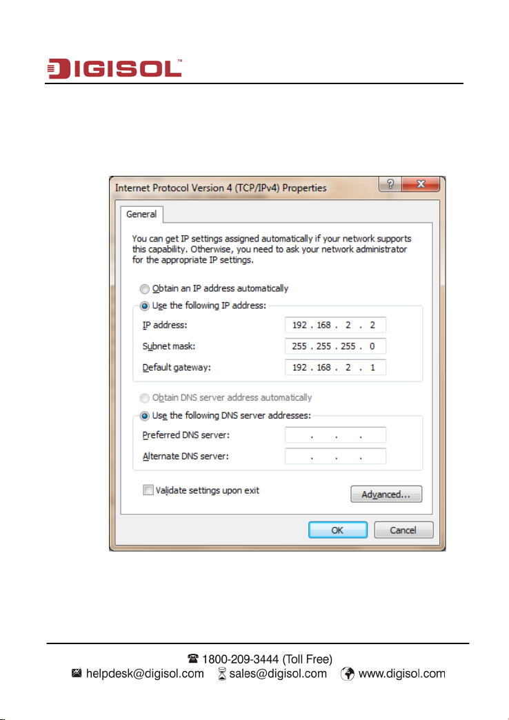
Step 4 Select Use the following IP address and enter the IP address of the network
adapter. The IP address must be 192.168. 2. X (X is a number in the range of 2 to
254). If you want to access the Internet through a wireless router, you need to enter
the default gateway and IP address of the DNS server correctly.
Step 5 Set the subnet mask and click OK.
17
Page 18
DG-BR4000N/E User Manual
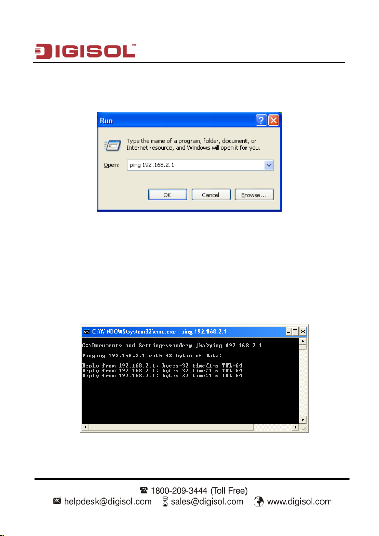
Step 6 Next, you can ping the default IP address of the wireless router, to check whether
the current connection between the PC and the wireless router is normal. Choose
Start > Run from the desktop and enter ping 192.168.2.1.
Note: 192.168.2.1 in the ping command is the default IP address of the LAN
interface. If the IP address changes, enter the current IP address instead.
Step 7 If the PC can ping through the default IP address of the wireless router, the
following page appears, indicating that the connection between your PC and the
wireless router is normal.
18
Page 19
DG-BR4000N/E User Manual
2-4 Wireless Connection
By default, the AP function of the wireless router is enabled. If you use a wireless network
adapter, do as follows to establish the connection:
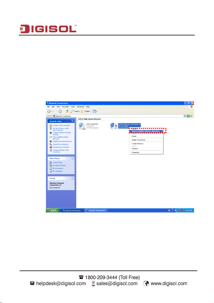
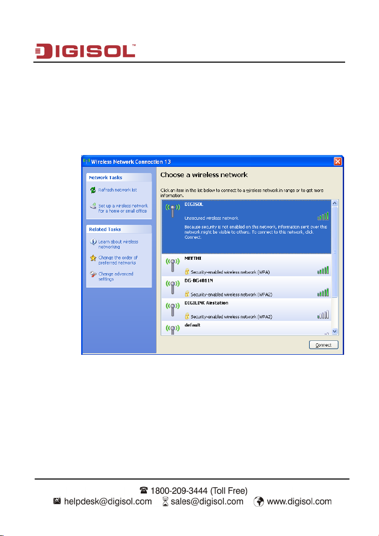
Step 1 Enable the wireless network adapter on your PC and ensure that the Wireless Zero
Configuration tool is available. Right-click the Wireless Network Connection icon
and choose View Available Wireless Networks from the menu.
19
Page 20
DG-BR4000N/E User Manual
Step 2 In the Wireless Network Connection page, click Refresh network list and the
network list is refreshed. The default SSID of the wireless router is DIGISOL.
Select the wireless router that you want to connect and click Connect. The default
wireless security mode is None, and you can connect the wireless router directly
without the encryption key in this mode. If the wireless router is encrypted, you
need to enter the correct key to connect to the wireless router.
20
Page 21
DG-BR4000N/E User Manual
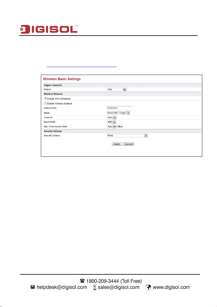
Step 3 If you are not sure of the available SSID, please log in to the Web page of the
wireless router, and view the SSID in the Wireless Basic Settings page of the
wireless settings. For more information about the wireless settings, please refer to
section 5-1 Wireless Basic Settings.
Note: After your wireless network card connects to the wireless router
successfully, you should set the network adapter to obtain an IP address
automatically. The configuration of wireless connection is now complete.
21
Page 22
DG-BR4000N/E User Manual
3. Software Installation
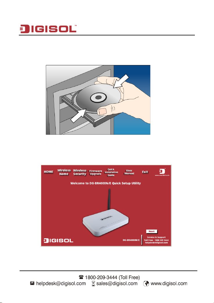
Insert the Setup CD into your CD-ROM drive of notebook/desktop computer.
Explore the CD and execute the “Smart Wizard.exe” file. Screen given below will be
displayed. Click ‘Next’ to continue.
22
Page 23
DG-BR4000N/E User Manual
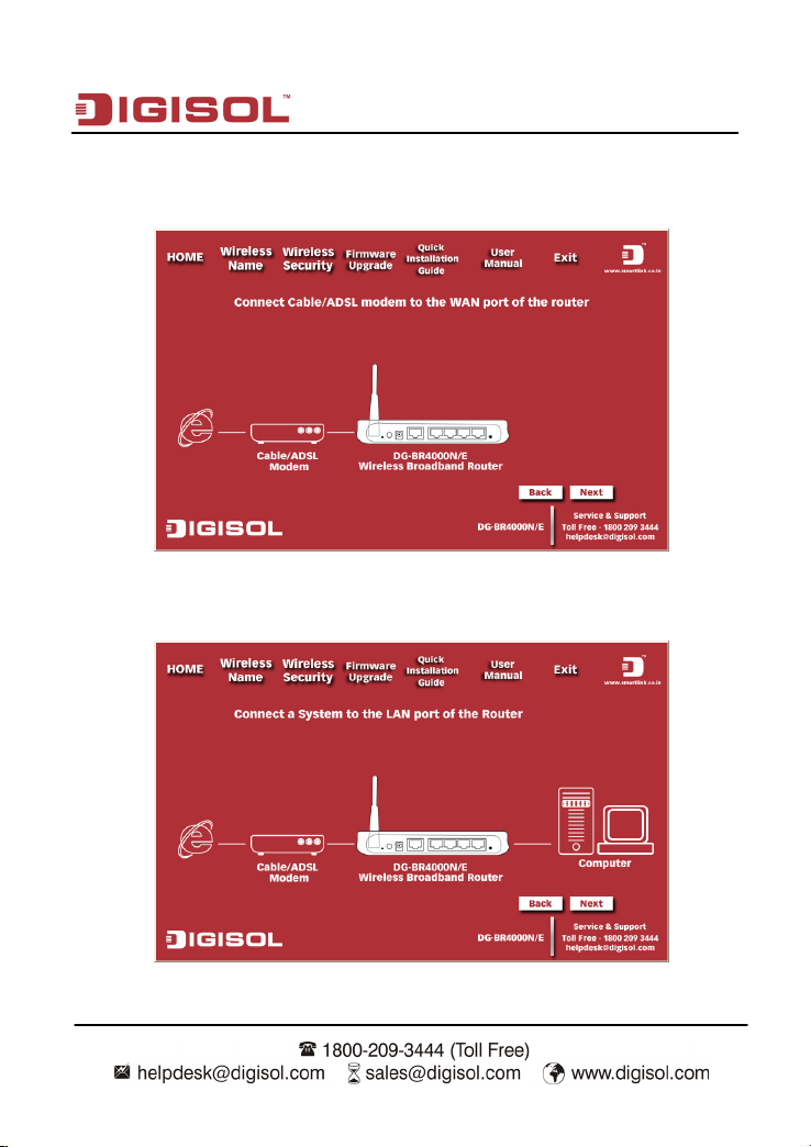
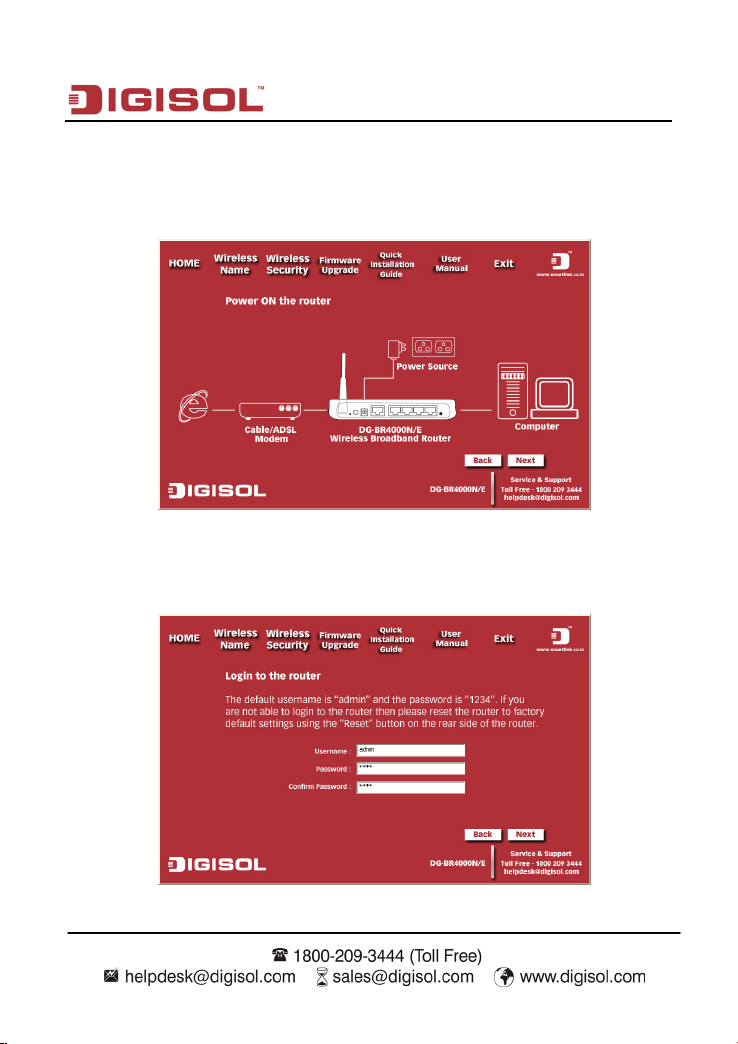
Connect one end of a network cable to the WAN port of the router and the other end to
the DSL/Cable modem. Click ‘Next’ to continue.
Connect one end of the provided network cable to one of the LAN ports (1~4) of the
router and the other end to your computer. Click ‘Next’ to continue with the installation.
23
Page 24
DG-BR4000N/E User Manual
Power on the Router. It will take approximately 30 seconds for the router to boot up
completely. Ensure that all the LED’s on the router are ON. If not, try the above steps
again else click ‘Next’ to continue.
Enter the Router’s password to log in to the Router. The default password is “1234”. Click
‘Next’ to continue.
24
Page 25
DG-BR4000N/E User Manual
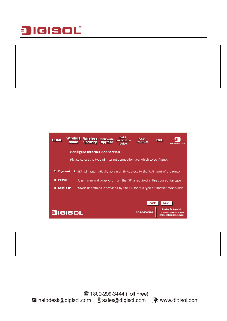
Note: The above mentioned steps are the common steps to be followed for
all the types of internet connection. The procedure to be followed after
these common steps for all the connection types have been explained
below.
Dynamic IP (DHCP)
Verify the Internet Connection Type the wizard has detected. If it is not correct, please
configure it manually. Click ‘Next’ to continue.
Note: If you are not sure which Internet Connection Type you use, please
contact your Internet Service Provider for this information.
25
Page 26
DG-BR4000N/E User Manual
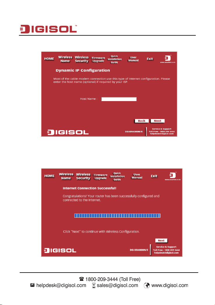
Enter the host name and click on ‘Next’.
Please wait while the Wizard tries to connect to the Internet. If you see the window
“Internet Connection Successful”, your router has been successfully connected to the
Internet. Please click ‘Next’ to configure the wireless settings.
26
Page 27
DG-BR4000N/E User Manual
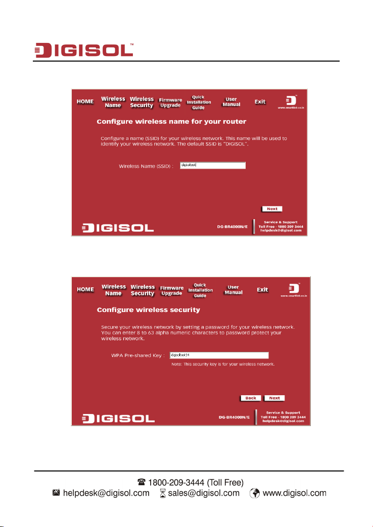
Configure a name for your wireless network. Click ‘Next’ to continue.
Click on ‘Next’ and enter the preshared key in the screen shown below.
27
Page 28
DG-BR4000N/E User Manual
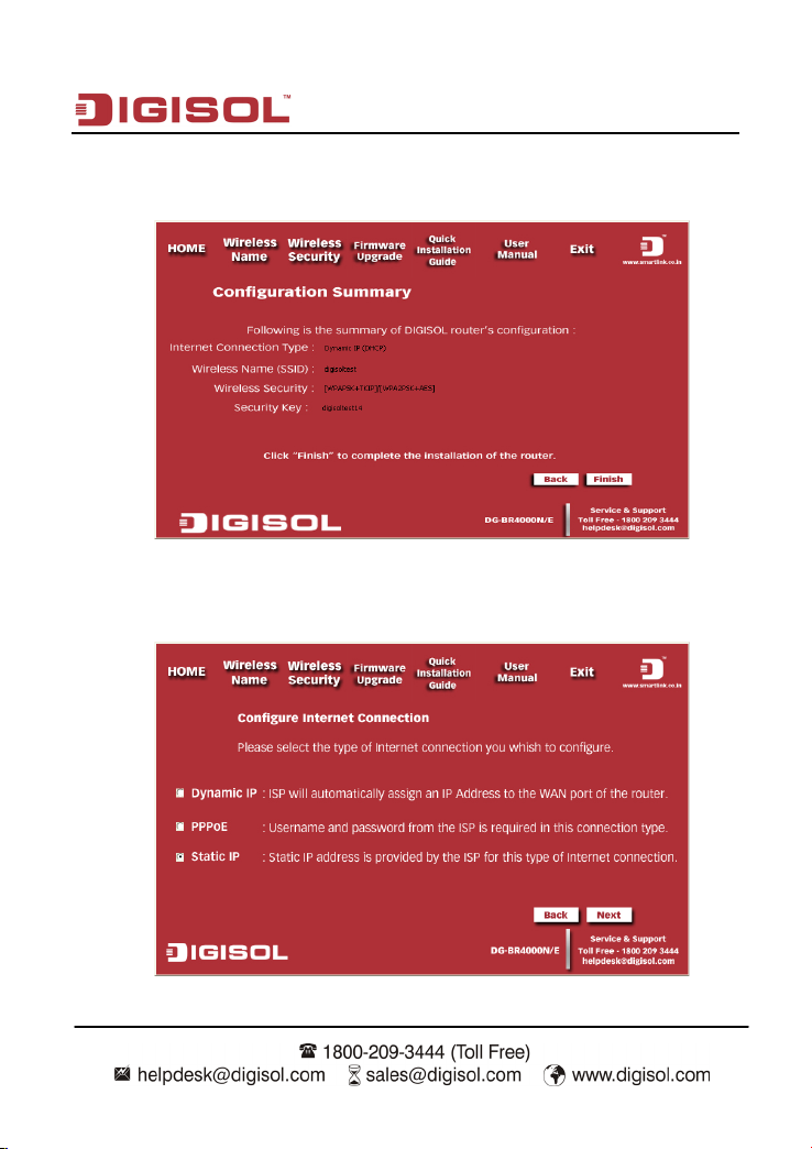
Click on ‘Next’ and the following summary will be displayed with the type of internet
connection.
Static IP
Select ‘Static IP’ in the internet connection types and click on ‘Next’.
28
Page 29
DG-BR4000N/E User Manual
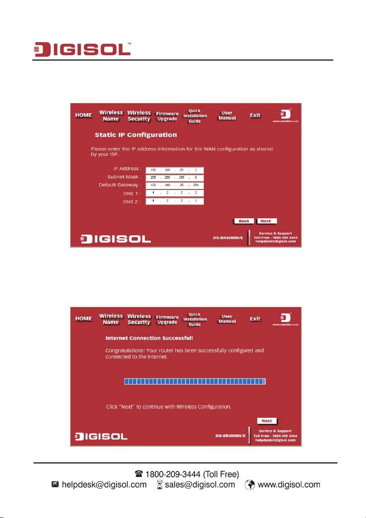
Enter the static IP, the subnet mask, the default gateway and the DNS addresses as
shown below. Then click on ‘Next’.
Please wait while the Wizard tries to connect to the Internet. If you see the window
“Internet Connection Successful”, your router has been successfully connected to the
Internet. Please click ‘Next’ to configure the wireless settings.
29
Page 30
DG-BR4000N/E User Manual
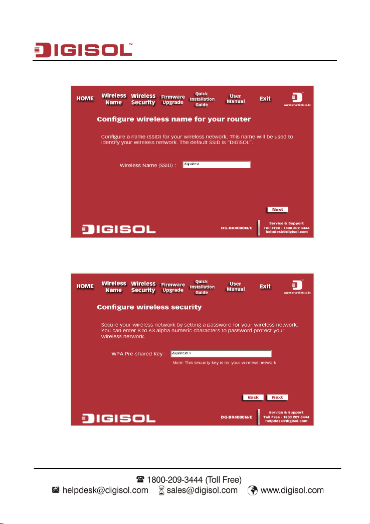
Configure a name for your wireless network. Click ‘Next’ to continue.
Click on ‘Next’ and enter the preshared key in the screen shown below.
30
Page 31

DG-BR4000N/E User Manual
Click on ‘Next’ and the following summary will be displayed with the type of internet
connection.
PPPoE
Select ‘PPPoE’ in the internet connection types and click on ‘Next’.
31
Page 32

DG-BR4000N/E User Manual
Enter the user name and password provided by your ISP then click ‘Next’.
Please wait while the Wizard tries to connect to the Internet. If you see the window
“Internet Connection Successful”, your router has been successfully connected to the
Internet. Please click ‘Next’ to configure the wireless settings.
32
Page 33

DG-BR4000N/E User Manual
Configure a name for your wireless network. Click ‘Next’ to continue.
Click on ‘Next’ and enter the preshared key in the screen shown below.
33
Page 34

DG-BR4000N/E User Manual
Click on ‘Next’ and the following summary will be displayed with the type of internet
connection.
34
Page 35

DG-BR4000N/E User Manual
4. Logging In to the Web Page
Run the Internet Explorer (IE), enter http://192.168.2.1/ (the default IP address of the wireless
router) in the address bar, and press Enter.
In the window that is displayed as shown in the following figure, set the Language to English,
enter the user name and password, and click Login.
Note: The default user name and password are admin and 1234
respectively.
35
Page 36

DG-BR4000N/E User Manual
After logging in to the Web page, you can view, configure and modify the router settings.
Caution:
If you are managing the wireless router through the Web page, do not cut
off the power supply. Otherwise, the changed settings will not be saved
4-1 Web Configuration
Setup Wizard
You can set the basic network parameters for accessing Internet by following this wizard.
To configure the setup wizard, do as follows:
Step 1 After login, click Setup Wizard in the navigation bar on the left pane of the page.
The Setup Wizard page shown below appears.
If you are familiar with the router settings, you can select No. I Want To Configure The Router
Myself. If you want to follow this wizard to configure the router, please select Yes and click
Next. The router automatically detects the WAN connection mode.
36
Page 37

DG-BR4000N/E User Manual
Note: If you do not insert the network cable into the WAN interface of the
wireless router, the previous page does not appear.
Step 2 The broadband type can be Dynamic IP (DHCP), Stat ic IP (Fixed) or PPPoE.
1) If the detected broadband type is Dynamic IP (DHCP), the following figure
appears:
Click Next and the following figure appears:
Enter the host name provided by the Internet service provider (ISP) in the Account Name field.
If the ISP does not provide it, you need not modify it.
In this mode, the WAN port of the wireless router obtains the network property information,
including the IP address, subnet mask, gateway and IP address of the DNS server, from the
connected DHCP server.
Next, click Apply and the settings take effect immediately. The setup wizard is now complete.
37
Page 38

DG-BR4000N/E User Manual
IP Address
Enter the IP address of the WAN interface.
IP Subnet Mask
Subnet mask of the WAN IP address. It is usually 255.255.255.0.
Gateway IP Address
Enter the IP address of the gateway if necessary.
Primary DNS
Enter the IP address of the primary DNS server if necessary.
2) If the detected broadband type is Static IP (Fixed), the following figure
appears:
Click Next and the following figure appears:
The following table describes parameters in this page:
Item Description
38
Page 39

DG-BR4000N/E User Manual
that DNS server.
Login
Enter the user name provided by the ISP.
Password
Enter the password provided by the ISP.
Service Name
Enter the service name provided by the ISP. If the ISP does
Secondary DNS
After the settings are done, click Apply and the settings will take effect immediately.
The setup wizard is now complete.
3) If the detected broadband type is PPPoE, the following figure appears:
Click Next and the following figure appears:
The following table describes parameters in this page:
If the ISP provides another DNS server, enter the IP address of
Item Description
39
Page 40

not provide it, you need not enter any information.
Domain Name Server
nter the IP address
ion is available, select Get
Automatically From ISP.
Primary DNS
Enter the IP address of the primary DNS server if necessary.
of that DNS server.
(DNS) Address
DG-BR4000N/E User Manual
Select Use these DNS Servers and e
information of the DNS server provided by the ISP. If no
DNS server informat
Secondary DNS
Note: The user name and password are case-sensitive. If you have any querries
about the user name and password, contact your ISP.
After the settings are done , click Apply and the settings take effect immediately. The setup
wizard is now complete.
If the ISP provides another DNS server, enter the IP address
4-2 Running Status
Click Running Status and the extended navigation menu is shown as follows:
The submenu contains Router Status and Clients List.
40
Page 41

DG-BR4000N/E User Manual
4-3 Router Status
Choose Running Status > Router Status and the Router Status page appears.
41
Page 42

DG-BR4000N/E User Manual
when the page is
refreshed for the last time and it is not refreshed any more.
This page displays the information of the current running status of the device, including
system information, connection status of the Internet port, LAN port, wireless port and
traffic statistics of each port.
Click Show Statistics and the St at istic Information page as shown in the following
figure appears:
This page displays the performance statistics information of the router, including the
number of sent and received packets at each port. The following table describes parameters
in this page:
Item Description
System Up Time
Set Interval Sets the interval for refreshing this page. Its value range is 1 to
Displays the time period that the router is running.
86400 seconds. Enter a value in the field and click Set Interval.
The settings take effect immediately. If you click Stop, this
page displays the statistics information
Click Connection Status in the Router Status page, and the Connection Status page
appears.
42
Page 43

DG-BR4000N/E User Manual
This page displays the information of current connection on the router.
If the WAN connection is set to PPPoE (Manually Connect), the Connection Status page
is as shown in the following figure:
The following table describes buttons in this page:
Item Description
Connect Click the button to interrupt the WAN connection.
Disconnect Click the button to start a new WAN connection.
43
Page 44

DG-BR4000N/E User Manual
If the WAN connection is set to DHCP, the Connection Status page is as shown in the
following figure:
The following table describes buttons in this page:
Item Description
Release Click the button to release the IP address.
Renew Click the button to obtain a new IP address.
If the WAN connection is set to any other mode, you can view the information, but not
perform any settings, in the Connection Status page.
For detailed description of the WAN connection modes, refer to
interface settings.
section 4-7 WA N
44
Page 45

DG-BR4000N/E User Manual
4-4 Clients List
Choose Running Status > Clients List and the Clients List page appears.
This page displays the information of computers connected to the router, including the IP
adress, device name and MAC address of each computer.
Click Refresh to refresh the information of the connected computers.
4-5 Network Settings
Click Network Settings and the extended navigation menu is shown as follows:
The submenu contains LAN Interface Settings and WAN Interface Settings as seen in
the figure above.
45
Page 46

DG-BR4000N/E User Manual
default IP is 192.168.2.1. You can change it if necessary.
mask according to the actual network status.
routing table. If it is set to Both or In Only, the router integrates
4-6 LAN Interface Settings
Choose Network Settings > LAN Interface Settings and the LAN Interface Settings page
appears.
In this page, you can configure the parameters of the LAN port. You can modify the IP
address of the LAN port according to the actual network environment.
The following table describes parameters and buttons in this page:
Item Description
IP Address Set the IP address that a LAN user uses to access the router. The
IP Subnet Mask Subnet mask of the LAN port. You can enter a different subnet
RIP Direction The mode in which the router sends and receives RIP packets. If it
is set to Both or Out Only, the router periodically broadcasts its
46
Page 47

DG-BR4000N/E User Manual
broadcast and RIP-2M uses multicast.
Server
server and
automatically assigns IP addresses for all connected computers.
(1 – 160 hours)
assigns new IP addresses for all connected computers.
network card accesses the DHCP server.
that is displayed.
Reservation page that is displayed.
it.
the received routing tables.
RIP Version The format of the RIP packets and broadcast mode that the router
sends them. RIP-1 is universally supported. Routing data sent by
using RIP-2B or RIP-2M is in RIP-2 format. RIP-2B uses subnet
Use Router as DHCP
Starting IP Address The first address in a consecutive IP address pool.
Ending IP Address The last address in a consecutive IP address pool.
DHCP Lease Time
Address Reservation If an IP address is reserved for the network card of a PC in a
Add Click the button to add an entry in the Address Reservation page
Edit Select an entry of reserved address and click the button to modify
Delete Select an entry of reserved address and click the button to delete
If it is selected, the router serves as the DHCP
After the DHCP lease time elapsed, the router automatically
LAN, the network card obtains the same IP address every time the
the IP address, MAC address or device name in the Address
47
Page 48

DG-BR4000N/E User Manual
entry to the Address Reservation Table.
address pool.
reserved.
reserved.
Table.
Click the Add button in the LAN Interface Settings page, and the Address Reservation
page is as follows:
The following table describes parameters and buttons in this page:
Item Description
Address Reservation
Table
IP Address Enter the IP address to be reserved. It must be within the IP
MAC Address Enter the MAC address of a computer whose IP address is to be
Displays entries of reserved addresses. You can select the
information of the local computer, or enter the IP address, MAC
address and device name of a computer, then click Add to add an
Device Name Enter the device name of a computer whose IP address is to be
Add Click the button to add the entry to the Address Reservation
Cancel Click the button to cancel the entry just set.
Refresh Click the button to refresh the page.
48
Page 49

DG-BR4000N/E User Manual
After the settings are done, click Add to add an entry to the Address Reservation Table.
Note: 1) If your IP address is changed, you must use the new IP address to
log in to the Web configuration page of the router and the default gateway
of all hosts in the LAN must be set to the new IP address for Internet
access.
2) The subnet mask of all hosts in the LAN must be consistent with the
subnet mask specified in the LAN Interface Settings page.
4-7 WAN Interface Settings
Choose Network Settings > WAN Interface Settings and the WAN Interface Settings
page appears.
49
Page 50

DG-BR4000N/E User Manual
The router supports 3 modes of WAN connection, including Dynamic IP (DHCP), Static IP
(Fixed) or PPPoE. In this page, you can select the appropriate WAN connection and
configure the relevant parameters according to the actual requirements.
• Dynamic IP (DHCP)
If you select static IP (DHCP), the router automatically obtains IP address, subnet mask
and IP address of the gateway from the ISP. Select this connection mode if the ISP does
not provide any IP network parameters. See the following figure:
50
Page 51

DG-BR4000N/E User Manual
Login?
provide it, you need not modify it.
Address
ormally, you can select Use
XX:XX:XX:XX:XX:XX.
The following table describes parameters in this page:
Item Description
Does your Internet
Connection Require A
Account Name Enter the host name provided by the ISP. If the ISP does not
Internet IP Address Select Get Dynamically From ISP.
Domain Name
Service (DNS)
Router MAC Address Physical address of the router. N
After the settings are done, click Apply to save the settings.
Select “No”
Enter the IP address of the DNS server provided by the ISP. If the
ISP does not provide it, select Get Automatically From ISP.
Default Address. If the ISP requires MAC address authentication,
select Use Computer MAC Address or Use This MAC Address. If
you select Use Computer MAC Address, the MAC address of the
current computer serves as the MAC address of the router. If you
select Use This MAC Address, you need to enter the MAC
address of another computer. The format of a MAC address is
51
Page 52

DG-BR4000N/E User Manual
Login?
provide it, you need not modify it.
• Static IP (Fixed)
If the ISP provides information of IP address, subnet mask, gateway and DNS server,
select Static IP (Fixed). For detailed settings, refer to your ISP.
The following table describes parameters in this page:
Item Description
Does your Internet
Connection Require A
Select “No”
Account Name Enter the host name provided by the ISP. If the ISP does not
Internet IP Address Select Use Static IP Address.
IP Address Enter the WAN IP address provided by the ISP. It cannot be null.
52
Page 53

DG-BR4000N/E User Manual
(Class C).
IP address used for connecting to the ISP.
Address
that DNS server.
XX:XX:XX:XX:XX:XX.
IP Subnet Mask Enter the WAN subnet mask provided by the ISP. It varies
depending on the network type. It is usually 255.255.255.0
Gateway IP Address Enter the IP address of the gateway provided by the ISP. It is the
Domain Name
Service (DNS)
Primary DNS Enter the IP address of the primary DNS server if necessary.
Secondary DNS If the ISP provides another DNS server, enter the IP address of
Router MAC Address Physical address of the router. Normally, you can select Use
After the settings are done, click Apply to save the settings.
Select Use These DNS Servers.
Default Address. If the ISP requires MAC address authentication,
select Use Computer MAC Address or Use This MAC Address. If
you select Use Computer MAC Address, the MAC address of the
current computer serves as the MAC address of the router. If you
select Use This MAC Address, you need to enter the MAC
address of another computer. The format of a MAC address is
53
Page 54

DG-BR4000N/E User Manual
A Login?
Provider
PPPoE
If the ISP provides the user name and password for PPPoE dialup, select PPPoE.
The following table describes parameters in this page:
Item Description
Does your Internet
Connection Require
Select “Yes”
Internet Service
Login Enter the user name for PPPoE dialup provided by the ISP.
Password Enter the password for PPPoE dialup provided by the ISP.
Select PPPoE.
54
Page 55

DG-BR4000N/E User Manual
•
If you select it, the system automatically
is disconnected
dialup connection after startup.
connection.
(DNS) Address
provide it, select Get Automatically From ISP.
that DNS server.
ormally, you can select Use
current computer serves as the MAC address of the router. If you
Service Name If several PPPoE servers are available, specify one in this field.
Dial On Demand: If you select it, the system automatically
establishes a connection when a network access request from
the LAN is received. If no network access request is sent from
the LAN within the set time of Idle Timeout, the system
automatically interrupts the connection. If you pay for Internet
access by time, you are recommended to use this connection
mode, which effectively saves the expense of Internet access.
Connection Mode
• Always On:
establishes a connection. If the network
because of external factors when you are using the Internet
access service, the system tries connecting every time (for
example, 10 seconds) until the connection is established. If
you pay for Internet access in the monthly fee mode, you are
recommended to use this connection mode.
• Manually Connect: If you select it, you need to manually set
Idle Timeout (In
minutes)
Domain Name Server
If the system does not detect any Internet access behavior within
the set time of idle timeout, the system interrupts the Internet
Enter the DNS address provided by the ISP. If the ISP does not
Primary DNS Enter the IP address of the primary DNS server if necessary.
Secondary DNS
Router MAC Address
If the ISP provides another DNS server, enter the IP address of
Physical address of the router. N
Default Address. If the ISP requires MAC address authentication,
select Use Computer MAC Address or Use This MAC Address. If
you select Use Computer MAC Address, the MAC address of the
55
Page 56

DG-BR4000N/E User Manual
address is
XX:XX:XX:XX:XX:XX.
select Use This MAC Address, you need to enter the MAC address
of another computer. The format of a MAC
After the settings are done, click Apply to save the settings.
56
Page 57

DG-BR4000N/E User Manual
5. Wireless Settings
Click Wireless Settings and the extended navigation menu is shown as follows:
The submenu contains Wireless Basic Settings, Guest Network, WPS Setup, Wireless
Advanced Settings and Wireless Repeater.
5-1 Wireless Basic Settings
Choose Wireless Settings > Wireless Basic Settings and the Wireless Basic Settings page
appears. In this page, you can configure the basic wireless parameters.
57
Page 58

DG-BR4000N/E User Manual
corresponding wireless network.
devices.
SSID is case-sensitive.
he default is Mixed
and 802.11g.
searches for the best channel in the available channels.
The following table describes parameters in this page:
Item Description
Region Select the region where you are in from the drop-down list.
Enable or disable SSID broadcast. If it is enabled, the router
Enable SSID
Broadcast
Enable Wireless
Isolation
Name (SSID)
broadcasts its SSID in the wireless network. In this way, wireless
clients can find the SSID after scanning and hence join the
Enable or disable wireless isolation. If it is selected, wireless
clients that use this SSID can access the Internet, but cannot
communicate with other wireless clients, Ethernet clients, or other
Network name. The SSID can contain up to 32 characters and can
be letters, numerals, hyphens and any combinations of them. The
Select the appropriate wireless mode. T
802.11b/g/n.
• 802.11b only: The maximum rate is 11 Mbps.
• 802.11g only: The maximum rate is 54 Mbps.
• 802.11n only: For 20M bandwidth, the maximum rate is 72
Mbps (In short preamble); for 40M bandwidth, the maximum
Mode
rate is 150 Mbps (In short preamble). You can select Long
preamble or Short Preamble in the Wireless Advanced Settings
page. For details, refer to section advanced wireless settings
• Mixed 802.11b/g: It is compatible with 802.11b and 802.11g.
• Mixed 802.11n/g: It is compatible with 802.11n and 802.11g.
• Mixed 802.11b/g/n: It is compatible with 802.11b, 802.11n
Select the working channel of the wireless network. The default is
Channel
Auto, which indicates that the wireless router automatically
58
Page 59

DG-BR4000N/E User Manual
Rate
system supports.
detail.
Band Width Select the bandwidth.
Max Transmission
Security Options
Security Options
Select one from the drop-down list that displays all rates that the
Set the security encryption of the wireless network, to prevent
unauthorized access and listening. You can select None, WEP,
WPA-PSK(TKIP), WPA2-PSK(AES), or WPA -PSK(TKIP)+
WPA2-PSK(AES). The following describes the security settings in
• None: Data encryption is not adopted and the network is not secure. Any station can
access the network. This option is not recommended.
• WEP: Wired equivalent privacy. You can encrypt the data with WEP 64 bits or 128
bits.
59
Page 60

DG-BR4000N/E User Manual
Typ e
he default is
Automatic.
Strength
128 bits.
digits. The key can be any combination of 0-9 and A-F.
PassPhrase
Enter 8-63 characters or 64 hexadecimal digits.
The following table describes parameters related to the WEP mode:
Item Description
Authentication
You can select Automatic or Shared Keys. T
Encryption
Key 1/2/3/4 Select one from the four keys and enter the corresponding WEP
Select the encryption strength of WEP. You can select 64 bits or
key in the field.
If the Encryption Strength is set to 64 bits, enter 10 hexadecimal
digits. The key can be any combination of 0-9 and A-F.
If the Encryption Strength is set to 128 bits, enter 26 hexadecimal
• WPA-PSK (TKIP): Preshared key Wi-Fi protection access. It uses WPA-PSK
standard encryption and Temporal Key Integrity Protocol (TKIP). TKIP has stronger
encryption mechanism and integrates message integrity code (MIC) to protect
against attacks of hackers.
The following table describes parameters related to the W PA -PSK (TKIP) mode:
Item Description
60
Page 61

DG-BR4000N/E User Manual
PassPhrase
Enter 8-63 characters or 64 hexadecimal digits.
PassPhrase
Enter 8-63 characters or 64 hexadecimal digits.
• WPA2-PSK(AES): Preshared key Wi-Fi protection access version 2. It uses
WPA2-PSK standard encryption and Advanced Encryption Standard (AES). AES
uses symmetric 128 bits block data to encrypt.
The following table describes parameters related to the W PA 2 -PSK(AES) mode:
Item Description
• WPA-PSK(TKIP)+ W PA 2 -PSK(AES): It allows the client to use WPA -PSK(TKIP)
or WPA 2 -PSK (AES).
The following table describes parameters related to the W PA -PSK(TKIP)+
WPA2-PSK(AES) mode:
Item Description
61
Page 62

DG-BR4000N/E User Manual
Note: After wireless settings are complete on the router, a host in the wireless
network must have consistent wireless settings, including the SSID, with the
router if the host wants to connect to the router. If the router has security
settings, the host in the wireless network must have consistent security
settings. For example, the passwords set on the host and the router must be
the same. Otherwise, the host cannot connect to the router.
5-2 Guest Network
If you enable guest network, a visitor can use Internet connection in your home without
knowing your wireless password.
Choose Wireless Settings > Guest Network and the Guest Network page appears.
62
Page 63

DG-BR4000N/E User Manual
, encryption mode,
information or modify the settings.
network.
Broadcast
broadcasts its SSID to all wireless stations.
the LAN of the wireless router.
cannot communicate with other wireless clients or Ethernet clients.
(SSID)
case-sensitive.
The following table describes parameters in this page:
Item Description
Brief description of the created guest network. You can create up to
four guest networks. A network profile contains the information of a
Network Profiles
guest network, including the number, SSID
whether the guest network is enabled and whether to broadcast SSID.
You can select the radio button of a profile to view the detailed
Enable Guest
Network
Enable SSID
Allow Guest to
access My Local
network
Enable Wireless
Isolation
Guest Wireless
Network Name
Security Options
After the settings are done, click Apply to save the settings.
Enable or disable a guest network. After it is enabled, you and the
visitor can connect to the network through the SSID of the guest
Enable or disable SSID broadcast. After it is enabled, the wireless AP
If it is enabled, users connected to the network of this SSID can
access not only the Internet but also the LAN of the wireless router,
like users connected to the network of the primary SSID. If this option
is disabled, users connected to the network of this SSID cannot access
Enable or disable wireless isolation. If it is enabled, wireless clients
connected to the network of this SSID can access the Internet, but
Name of the guest network. The SSID can contain up to 32 characters
and can be any combination of letters, numerals and hyphen. It is
Refer to description and setting methods of Security Options in
section 10 Security options.
63
Page 64

DG-BR4000N/E User Manual
5-3 WPS Setup
Choose Wireless Settings > WPS Setup and the WPS Setup page appears.
WPS refers to Wi-Fi Protected Setup. You can use the WPS setup function to add a
wireless client to a network, without setting specific parameters, such as SSID, security
mode and password. To use this function, a wireless client must support WPS. If the
wireless client does not support WPS, you must manually configure the wireless client to
ensure that it has consistent SSID and wireless security settings with the router. There are
two WPS modes: Push Button and PIN. Click Next to select the WPS mode.
• Push Button mode
Select Push Button (recommended) and click Start PBC or press the WPS button on the
router and the following page appears:
64
Page 65

DG-BR4000N/E User Manual
Press the button on the network card or click the button in the software page within two
minutes to start WPS connection. After WPS connection is established, the following page
appears. The client can now visit the LAN.
• PIN mode
Select PIN (Personal Identification Number) and enter the PIN of the network (refer to the
client of the network card), then click Start PIN to start WPS connection. The following
page appears:
Click the PIN button on the client of the network card within two minutes to start WPS
connection. After WPS connection is established, the following page appears. The client
can now visit the LAN.
65
Page 66

DG-BR4000N/E User Manual
Radio
wirelessly.
2346.
station responds with a Clear to Send (CTS) frame to the router,
5-4 Wireless Advanced Settings
Choose Wireless Settings > Wireless Advanced Settings and the Wireless Advanced
Settings page appears.
The following table describes parameters in this page:
Item Description
Enable Wireless Router
When this field is enabled you can connect to the router
Fragmentation Length
(256-2346)
CTS/RTS Threshold
(1-2347)
Set the threshold of fragmentation length. If the length of a
packet is greater than the value, the packet is automatically
fragmented into several packets. Because too many packets
lead to low performance of the wireless network, the value of
Fragmentation Length cannot be too small. The default value is
Set the CTS/RTS threshold. If the length of a packet is greater
than the value, the router sends an RTS frame to the destination
station to negotiate. After receiving the RTS frame, the wireless
66
Page 67

DG-BR4000N/E User Manual
default value is 2346.
video and voice-over-IP telephony.
which indicates to transmit full power.
need to enter PIN on the wireless client.
menu item is greyed out.
the PIN mode option is greyed out.
in the Wireless Basic Settings page.
or delete entries in the Wireless Card Access List page.
indicating that they can communicate with each other. The
Preamble Mode Set the preamble mode. The default is Long preamble.
A preamble (especially the 802.11b High Rate/DSSS PHY
field; 56 digits synchronized field for short preamble) defines
the length of the CRC correction block for communication
between wireless devices. Shorter settings should be applied in
a network of intense traffics. Short preamble is mainly used to
improve the efficiency of a wireless network for applications
that have high requirement of real-time, such as streaming
Transmit Power Control Set the transmit power of the router. The default is 100%,
Router’s PIN To configure wireless settings of the router through WPS, you
Enable WPS Functions in the WPS Setup page are available only after this
option is selected. If this option is not selected, the WPS Setup
Disable Router’s PIN The PIN mode function in the WPS Setup page is available
only after this option is selected. If this option is not selected,
Keep Existing Wireless
Settings
Wireless Card Access
Control List
It determines whether WPS is configured on the router. If this
option is not selected, newly added wireless clients change the
wireless settings of the router into random SSID and security
key that are automatically generated. You can select this option
You can set to allow only network cards of specific PCs to
access your wireless network according to the MAC address of
the network card of a PC. Click Setup Access List to add, edit,
67
Page 68

DG-BR4000N/E User Manual
Control On
restrict wireless network cards according to their MAC addresses.
Wireless Card Access Setup page that is displayed.
Access Setup page that is displayed.
it.
Click Setup Access list button and the Wireless Card Access List page appears:
The following table describes parameters and buttons in this page:
Item Description
Turn Access
Add Click the button to add an entry of wireless network card in the
Edit Select an entry of wireless network card and click the button to
Delete Select an entry of wireless network card and click the button to delete
Click the Add button and the Wireless Card Access Setup page appears:
Enable or disable wireless access control. If it is selected, you can
modify the device name or MAC address in the Wireless Card
68
Page 69

DG-BR4000N/E User Manual
up to 16 entries of MAC addresses.
Device Name
Name of the device. You can customize it.
characters.
The following table describes parameters in this page:
Item Description
Available Wireless
Cards
Mac Address Physical address of the network card. It is a string of 12
After the settings are done, click Add to add a wireless card entry. Then, click Apply to
save the settings in the Wireless Advanced Settings page.
It displays all the available wireless network cards of PCs
and their MAC addresses. Click the radio button of a network
card to select its MAC address. If the list does not contain
your desired wireless network card, you can manually enter
the MAC address of the wireless network card. You can enter
69
Page 70

DG-BR4000N/E User Manual
his function cannot be
can change the channel.
5-5 Wireless Repeater
Wireless distribution system (WDS) enables interconnection between APs in an IEEE
802.11 wireless network. It extends the wireless network through several APs, without
connection of wired backbone network. This function is also called wireless repeating or
bridging.
Choose Wireless Settings > Wireless Repeating Function and the Wireless Repeater
page appears.
The following table describes parameters in this page:
Item Description
Enable or disable wireless repeating.
If the channel is set to Auto, t
Enable Wireless Repeater
enabled. If you try enabling the function when the channel
is set to Auto, the system gives an error and automatically
switches to the Wireless Basic Settings page, where you
70
Page 71

DG-BR4000N/E User Manual
Association
n this mode, the router serves as a repeater to
communicate with the central base station.
station.
Address
ou can add up to four
repeaters. Repeaters should be configured accordingly.
1 2 3 4
Disable Wireless Clients
Wireless Repeater
Repeater IP Address
Basic Station MAC
Wireless Basic Station
Repeater MAC Address
After the settings are done, click Apply to save the settings.
If it is selected, clients cannot access the LAN.
I
Enter the IP address of the repeater. It must be in the same
network segment as the IP address of the central base
Enter the physical address of the central base station.
In this mode, the router serves as the central base station to
communicate with repeaters. Y
repeaters. The central base station forwards the data of
communication between repeaters to the destination
Enter the physical address of the repeater.
71
Page 72

DG-BR4000N/E User Manual
6. Forwarding Rule
Click Forwarding Rule and the extended navigation menu is shown as follows:
The submenu contains Port Forwarding, Port Triggering and UPnP.
6-1 Port Forwarding
By default, the firewall function of the router hides your LAN. As a result, other users on
the Internet can detect only the router, but cannot access a certain PC in the LAN directly.
If you want to access a PC in a LAN, you need to configure port forwarding on the router
and map the desired port to the corresponding PC in the LAN. After receiving an access
request from the Internet, the router forwards the packets to the PC according to the rule of
port mapping. In this way, communication is successfully established between the Internet
and the PC in the LAN.
Choose Forwarding Rule > Port Forwarding and the Port Forwarding page appears.
72
Page 73

DG-BR4000N/E User Manual
Service Name
Select a service type from the drop-down list.
Address
provided.
Add
Click the button to add a service.
name, start port, end port and server IP address.
page that is displayed.
Service
service in the Ports - Custom Service page that is displayed.
The following table describes parameters and buttons in this page:
Item Description
Service IP
Service List
Edit Service
Delete Service Delete a service entry.
Add Custom
Click the Add Custom Service button and the Ports - Custom Service page appears:
Enter the IP address of the computer on which the service is to be
Displays the information of configured services, including the service
Click the button to edit a service entry in the Ports - Custom Service
If the list does not contain your desired service, click the button to add a
73
Page 74

DG-BR4000N/E User Manual
Service Name
Add a custom name in this field.
TCP, UDP or TCP/UDP.
fter the connection to the mapping port is established, the
connection requests to the open port.
Ending Port
Set the end port of the mapping port range.
Address
provided.
The following table describes parameters in this page:
Item Description
Protocol
Starting Port
Server IP
After the settings are done, click Apply to save the settings.
Indicate the protocol that is used at the mapping port. You can select
A
corresponding port is open and the application can initiate consequent
Enter the IP address of the computer on which the service is to be
6-2 Port Triggering
Certain applications, such as WAN network games, video conferences and network calls,
require multiple connections. Because of the firewall setting, these applications cannot
work on a simple NAT router. However, certain special applications enable the
applications to work on a NAT router. When an application sends a connection request to a
trigger port, the corresponding ports are open, for later connection and service provision.
Choose Forwarding Rule > Port Triggering and the Port Triggering page appears.
74
Page 75

DG-BR4000N/E User Manual
Triggering
minutes)
timer, the ingress port is disabled.
is displayed.
page that is displayed.
Delete Service
Click the button to delete a selected rule.
The following table describes parameters in this page:
Item Description
Enable Port
Enable or disable port triggering.
Port Triggering
Timeout (in
Add Service
Edit Service
Click the Add Service button and the Port Triggering – Services page appears:
Enter a value not greater than 9999. The timeout value controls the
inactive timer at the specified ingress port. Upon timeout of the inactive
Click the button to add a rule in the Port Triggering – Services page that
Click the button to edit a selected rule in the Port Triggering – Services
75
Page 76

DG-BR4000N/E User Manual
Service Name
Enter the service name.
PC.
UDP or TCP/UDP.
starting port. Otherwise, other relevant ports are not open.
Ending Port
Typ e
triggering port is successful, the
connection requests to the open ports.
The following table describes parameters in this page:
Item Description
You can select Any or Single address.
• Any: Allow everybody in the user network to use the service.
Service User
• Single address: Enter the IP address of the network card on the PC.
Then, the service is applied only on the specific network card of the
Service Type
Triggering
Starting Port
Triggering
Connection
Starting Port
Ending Port Set the end port of the triggering port range.
After the settings are done, click Apply to add the rule of port triggering.
Indicate the protocol used at the triggering port. You can select TC P,
The first port to which an application sends a connection request. All
relevant ports can be open only after connection is established at this
Set the end port of the triggering port range.
You can select TCP, UDP or TCP/UDP.
When the connection to the
corresponding ports are open and the application can send consequent
76
Page 77

DG-BR4000N/E User Manual
Turn UPnP On
Enable or disable UPnP.
minutes)
1440 minutes and the default is 30 minutes.
(in hops)
packet to broadcast before it vanishes. The value should be in the range
6-3 UPnP
By using the Universal Plug and Play (UPnP) protocol, a host at the LAN side can ask the
router to realize specific port conversion, so that an external host can access resources on
the internal host when necessary. For example, if MSN Messenger is installed on Windows
ME and Windows XP operating systems, UPnP can be used for audio and video
conversations. In this way, functions restricted by NAT can work properly.
Note: Only applications that support UPnP can use the function. The
functionality of UPnP requires support by the application and operating
systems such as Windows ME, Windows XP and Windows Vista.
Choose Forwarding Rule > UPnP and the UPnP page appears.
The following table describes parameters in this page:
Item Description
Advertisement
Period (in
Advertisement
Time To live
Set the broadcast interval. It indicates the interval for broadcasting the
UPnP information by the router. The value should be in the range of 1 to
The time for the broadcast to live. It is the number of hops after each
UPnP packet is sent. The number of hops is the time taken for each
77
Page 78

UPnP Portable
lists the types and status of the open ports.
Table
DG-BR4000N/E User Manual
of 1 to 255 hops and the default is 4 hops.
This table shows the IP addresses of UPnP devices that are connected to
the router and open (internal and external) ports on the devices. It also
78
Page 79

DG-BR4000N/E User Manual
7. Access Control
Click Access Control and the extended navigation menu is shown as follows:
The submenu contains Block Sites, Block Services and QoS Setup.
7-1 Block Sites
Choose Access Control > Block Sites and the Block Sites page appears.
79
Page 80

DG-BR4000N/E User Manual
• Always: Website blocking is always enabled.
readings, included in a link.
list under the button.
Names
Keyword
to delete it from the list.
the list.
IP Address To
accessing the Internet.
In this page, you can add or delete a filter rule of domain name or keyword, to block LAN
users from accessing certain websites in the WAN. When a user tries accessing a restricted
website, a message appears, indicating that the firewall restricts access to the website.
The following table describes parameters and buttons in this page:
Item Description
Select the mode of blocking. You can select Never, Per Schedule or
Always.
Keyword
Blocking
• Never: Website blocking is disabled.
• Per Schedule: After you select it and set in System Tools >
Schedules page, website blocking is enabled
according to the settings in the Schedules page.
Type Keyword
or Domain
Name Here
Add Keyword
Block Sites
containing
these Keywords
or Domain
Delete
Clear List
Allow Trusted
Enter the keyword or domain name that you want to block.
Domain name: For example, www. facebook.com
Keyword: Enter certain words, for example, blasphemy or erotic
Click the button to add the keyword or domain name you entered to the
The list displays the blocked entries. It can contain up to 32 entries.
Select a keyword or domain name in the above list and click the button
Click the button and all keywords and domain names are deleted from
After it is selected, the specified computer has the full authority of
80
Page 81

Visit Blocked
Sites
Address
in the fourth field.
DG-BR4000N/E User Manual
Trusted IP
After the settings are done, click Apply to save the settings.
Specify the IP address of a computer. You need to enter only a numeral
81
Page 82

DG-BR4000N/E User Manual
• Always: Service blocking is always enabled.
Rules Table
service entry according to your requirement.
Services Setup page that is displayed.
that is displayed.
7-2 Block Services
Choose Access Control > Block Services and the Block Services page appears.
In this page, you can set rules of service blocking, to block users from Internet access.
The following table describes parameters and buttons in this page:
Item Description
Select the mode of service blocking. You can select Never, Per
Schedule or Always.
• Never: Service blocking is disabled.
Services Blocking
• Per Schedule: After you select it and set in System Tools >
Schedules page, service blocking is enabled
according to the settings in the Schedules page.
Block Service
Add
Edit
The table lists all services to be blocked. You can add, edit or delete a
Click the button to add a rule of service blocking in the Block
Select a rule of service blocking in the Block Service Rules Table
and click the button to edit the rule in the Block Services Setup page
82
Page 83

DG-BR4000N/E User Manual
and click the button to delete it.
down list, the corresponding
information is already preset.
TCP, UDP or TCP/UDP.
starting port. Otherwise, other relevant ports are not open.
Delete
Click Add and the Block Services Setup page appears:
The following table describes parameters in this page:
Select a rule of service blocking in the Block Service Rules Table
Item Description
Select a service type from the drop-down list. If your desired type is
not in the list, select User defined. Then, you need to select the
Service Type
protocol, enter the service name and specify the port range. For
services that exist in the drop-
Protocol
Starting Port
Ending Port Set the end port of the service port range.
Indicate the protocol that is used at the service ports. You can select
The first port to which an application sends a connection request. All
relevant ports can be open only after connection is established at this
83
Page 84

DG-BR4000N/E User Manual
Defined
All IP Address: Network cards of all computers are blocked.
Service
Type/User
Filter Service
For
After the settings are done, click Add to add a new rule. Then, click Apply to save the
settings in the Block Services page.
Enter the service name.
It determines the computers to be blocked.
Only This IP Address: Only one network card on a computer is
blocked. You need to enter the IP address of a network card on a
computer.
IP Address Range: Network cards that correspond to a range of IP
addresses are blocked. You need to enter the starting and ending
addresses of the IP address range.
7-3 QoS Setup
Choose Access Control > QoS Setup and the QoS Setup page appears.
84
Page 85

DG-BR4000N/E User Manual
support WMM.
Table page.
value is in units of Mbps, the maximum value is 100.
Internet access behaviors by other users in the network.
numeral in the fourth field.
The QoS function sets priority policies on applications, online games, Ethernet LAN ports
and MAC addresses, sets an order for various network traffics, and thus optimizes your
network performance.
The following table describes parameters in the QoS Setup page:
Item Description
Enable WMM
(Wi-Fi
multi-media)
Settings
Enable or disable WMM. Wireless Multimedia (WMM) is a subset
of the 802.11e standard. It supports setting priorities of wireless
traffics according to data types within a certain range. Time-related
information such as audio and video has higher priority than normal
data. To ensure proper performance of WMM, wireless clients must
Turn Internet Qos
Access On
Turn Bandwidth
Control On
Setup QoS rule Click the button and the QoS Setup page is displayed
Enable Trusted IP
Address
Trusted IP Address Specify the IP address of a computer. You need to enter only a
Click Setup QoS Rule and the QoS Setup page appears:
Enable or disable QoS. After it is enabled, you can optimize the
network access traffics according to the settings in the QoS Priority
Set the maximum uplink bandwidth at the WA N port.
If the value is in units of Kbps, the maximum value is 1000. If the
After it is enabled, you can reserve half egress bandwidth for a
specified computer, to avoid impact to the computer because of
85
Page 86

DG-BR4000N/E User Manual
ports, online games and MAC addresses in the QoS Priority Table.
address of a
computer in the QoS – Priority Rules page that is displayed.
The following table describes the buttons in this page:
Item Description
Edit
Delete Click the button to delete a rule in the QoS Priority Table.
Add Priority
Rule
Click the Add Priority Rule button and the QoS – Priority Rules page for an application
appears:
Click the button to change the priorities of the applications, LAN
Click the button to set priority policy for an online game, an
application, an Ethernet LAN port, or the MAC
86
Page 87

DG-BR4000N/E User Manual
is not in the drop-down list, select Add A New Application.
TCP/UDP, TCP or UDP.
starting port. Otherwise, other relevant ports are not open.
The following table describes parameters in this page:
Item Description
QoS Policy For Enter the name of the QoS policy.
Priority Category Select Applications.
Applications
Priority You can select Highest, High, Normal or Low.
Connection Type
Starting Port
Ending Port Set the end port of the port range.
The QoS - Priority Rules page for an online game is as follows:
Select an application that you want to set. If your desired application
Indicates the protocol that is used at the port. You can select
The first port to which an application sends a connection request. All
relevant ports can be open only after connection is established at this
87
Page 88

DG-BR4000N/E User Manual
game is not in the drop-down list, select Add a new Game.
TCP/UDP, TCP or UDP.
starting port. Otherwise, other relevant ports are not open.
The following table describes parameters in this page:
Item Description
QoS Policy For Enter the name of the QoS policy.
Priority Category Select On-line Gaming.
On-line Gaming
Priority You can select Highest, High, Normal or Low.
Connection Type
Starting Port
Ending Port Set the end port of the port range.
The QoS – Priority Rules page for a LAN port is as follows:
Select an online game that you want to set. If your desired online
Indicates the protocol that is used at the port. You can select
The first port to which an application sends a connection request. All
relevant ports can be open only after connection is established at this
88
Page 89

DG-BR4000N/E User Manual
The following table describes parameters in this page:
Item Description
QoS Policy For Enter the name of the QoS policy.
Priority Category Select Ethernet LAN Port.
Ethernet LAN Port Select the LAN port that you want to set. You can select 1, 2, 3 or 4.
Priority You can select Highest, High, Normal or Low.
The QoS - Priority Rules page for a MAC address is as follows:
The following table describes parameters in this page:
Item Description
QoS Policy For Enter the name of the QoS policy.
Priority Category Select MAC Address.
MAC Device List Display the existing priority rules of computers that have higher
89
Page 90

DG-BR4000N/E User Manual
the list.
priority.
priority.
modify the priority rule.
delete the priority rule from the list.
to the QOS set up
priorities according to MAC addresses.
Enter the MAC address and device name of a computer for which
you want to set high priority, and then click Add to add the rule to
MAC Address
Device Name
Priority You can select Highest, High, Normal or Low.
Add Click the button to add a priority rule to the MAC Device List.
Edit
Delete
Cancel
After the settings are done, click Apply to save the settings. Then, click Apply to save the
settings in the QoS Setup page.
Enter the MAC address of a computer for which you want to set high
Enter the device name of a computer for which you want to set high
Select a priority rule in the MAC Device List and click the button to
Select a priority rule in the MAC Device List and click the button to
On clicking cancel you will exit from the Priority rule and get back
90
Page 91

DG-BR4000N/E User Manual
Service
Provider
3322.org, freedns.afraid.org, DtDNS.com or www.oray.cn.
provider.
8. Dynamic DNS
Dynamic DNS (DDNS) is mainly used to map fixed domain names to dynamic IP
addresses and vice versa. For a user using a dynamic IP address, after the user obtains a
new IP address when accessing Internet, the dynamic domain name software installed in
the host sends the IP address to the dynamic domain name resolution server provided by
the DDNS service provider and updates the domain name resolution database. When
another user on the Internet tries accessing the domain name, the dynamic domain name
resolution server returns the correct IP address.
Click Dynamic DNS and the Dynamic DNS page appears. In this page, you can configure
the DDNS parameteres.
The following table describes parameters in this page:
Item Description
User a
Dynamic DNS
Enable this function if you already register to the DDNS service
provider.
Service
Host Name
Select a server from the drop-down list. You can select DynDNS.org,
Enter the host name or domain name provided by the DDNS service
91
Page 92

DG-BR4000N/E User Manual
User Name Enter the user name of the DDNS account.
Password Enter the password of the DDNS account.
After the settings are done, click Apply to save the settings.
9. Static Routing
Static routing is a special type of routing that can be applied properly in a network to
reduce the problem of routing selection and overload of data flow because of routing
selection and to improve the forwarding speed of packets. You can set the destination IP
address, subnet mask and gateway to specify a routing rule. The destination IP address and
subnet mask are used to determine a destination network or host. Then, the router sends
packets to the specified destination network or host through the gateway.
Click Static Routes and the Static Routes page appears. In this page, you can add, edit and
delete a static routing rule, and view the current static routing table in the router.
92
Page 93

DG-BR4000N/E User Manual
Address
Mask
Address
route is direct connection, set the Metric to 2.
Click Add and the following figure appears:
The following table describes parameters of adding a routing rule:
Item Description
Active Enable it to apply the routing rule.
Router Name Enter the name of the static route.
Destination IP
Enter the destination IP address or network that you want to access.
IP Subnet
Gateway IP
Metric
After the settings are done, click Apply to save the settings.
Subnet mask of the destination IP address.
IP address of the router or host to which packets are sent.
Indicates the number of hops in the user network. Its value range is 2 to
15. Usually, the value of 2 or 3 leads to the best performance. If the
93
Page 94

DG-BR4000N/E User Manual
10. Security Options
Click Security Options and the extended navigation menu is shown as follows:
The submenu contains Remote Management and WAN Setup.
10-1 Remote Management
Choose Security Options > Remote Management and the Remote Management page
appears.
The remote management function allows you to configure the router’s WAN through the
Web browser. In this way, you can manage the router from a remote host.
94
Page 95

DG-BR4000N/E User Manual
On
the address bar (of IE) or the location bar (of Netscape).
• Everyone: Everyone on the Internet can access the router.
The following table describes parameters in this page:
Item Description
Turn Remote
Management
Enable or disable remote Web management.
Remote
Management
Address
Port Number Specify the port of Web management for accessing the broadband router.
IP address that is used to access the router from the Internet. The default
IP is http://0.0.0.0:8080
the WAN IP address of the router, along with : and the port number in
Set the IP address of the computer on which remote Web management is
carried out to access the router.
. When accessing the router, you need to enter
• Only This Computer: Only the specified IP address can access the
Allow Remote
Access By
After the settings are done, click Apply to save the settings.
router. You need to enter an IP address.
• IP Address Range: A number of IP addresses on the Internet can
access the router. You need to enter the starting
and ending IP addresses to specify the range.
95
Page 96

DG-BR4000N/E User Manual
Protection
select the check box unless it is necessary.
10-2 WAN Setup
Choose Security Options > WAN Setup and the WAN Setup page appears.
In this page, you can set a default DMZ server and allow the router to respond to the ping
command from the Internet. Do not use the two functions unless it is necessary because
they lead to security risks. DMZ allows all ports of a PC in your LAN to be exposed to the
WA N . Enter the IP address of a PC to set the PC to a DMZ host, which is not restricted by
the firewall any more. In this way, the DMZ host can have mutually unrestricted
communcation with a user or server on the WAN.
The following table describes parameters in this page:
Item Description
Disable Port
Scan and DOS
This function protects your LAN against DoS attack. Do not disable this
firewall function unless a special situation occurs.
Respond to
Ping on
Internet Port
If you want the router to respond to ping commands from the Internet,
select the check box. The ping command can be used for diagnosis. Like
a DMZ server, this function also leads to security risks. Hence, do not
96
Page 97

DG-BR4000N/E User Manual
from the Internet. If you do not want to use IGMP proxy, select the
check box to disable IGMP proxy.
Server
your ISP connection.
allows running of almost all network applications.
check box to enable IPv6 pass-through.
Disable IGMP
Proxying
Default DMZ
MTU Size (in
bytes)
IGMP proxy allows a PC in the LAN to receive certain multicast traffics
Enter the IP address of a computer or server that serves as a DMZ ser ver.
The maximum transmission unit. Normally, it is 1500 bytes for most
Ethernet networks, 1492 bytes for PPPoE connection and 1436 bytes for
PPTP connection. Certain ISPs may require smaller MTU, but this is a
rare case. Do not modify the value of MTU size unless it is necessary for
Determines the mode of the router to handle the input traffics.
• Secured: It provides a secure firewall that protects personal
computers in a LAN against attacks from the Internet.
NAT Filtering
However, it causes malfunction of certain network
games, point-to-point (P2P) applications and multimedia
applications.
• Open: It provides firewall settings of a lower security level. It
Enable IPv6
Pass-Through
After the settings are done, click Apply to save the settings.
By default, IPv6 pass-through is disabled. If your configuration contains
IPv6 devices and you want to replace IPv4 with IPv6, you can select the
97
Page 98

DG-BR4000N/E User Manual
11. System Tools
Click System Tools and the extended navigation menu is shown as follows:
The submenu contains Schedules, SNTP, Backup Settings, Set Password and Router
Upgrade
11-1 Schedules
Choose System Tools > Schedules and the Schedules page appears.
98
Page 99

DG-BR4000N/E User Manual
Days to Block
Select every day, one day, or several days.
Note that the system uses 24-hour clock.
If you already set content filtering in the Block Sites page or set sevice filtering in the Block
Services page, you can set a schedule to specify the time and mode of restricting Internet
access.
The following table describes parameters in this page:
Item Description
If you want to fully restrict access every day, select All Day.
Time of Day to Block
(Use 24-hour clock)
After settings are done, click Apply to save the settings.
If you want to restrict access in a specific time during certain
days, select the days and enter the starting time and ending time.
11-2 SNTP
Choose System Tools > SNTP and the SNTP page appears.
99
Page 100

DG-BR4000N/E User Manual
server.
•
drop-down list.
temporarily advancing clocks during the summertime so that
saving the lighting power.
Offset
standard time becomes 11:00 in the morning in DST.
Dates
In this page, you can set the time information of your router. It is strongly recommended to
set the correct time on the router first. This ensures proper functioning of log, site blocking
and schedule, because these functions are based on the time setting in this page.
The following table describes parameters in this page:
Item Description
Automatically synchronize with Internet time servers: Enable or
disable automatic synchronization with the network time server.
Time Setting
• First NTP time server: Enter the URL of the primary network
time server.
• Second NTP time server: Enter the URL of the secondary time
Current Router Time: Displays the current system time of the
Time
Configuration
Enable Daylight
Saving
router.
• Time Zone: Select the time zone that the router is in from the
Enable or disable daylight saving time (DST), which is a practice of
afternoons have more daylight and mornings have less. It helps
Daylight Saving
Daylight Saving
After the settings are done, click Apply to save the settings.
Select a proper offset. If it is set to +1:00, 10:00 in the morning in
Set the starting time and ending time of DST.
100
 Loading...