

Page 1
DG-BG4100NU
150Mbps Wireless ADSL2/2+ Broadband Router with USB Port
User Manual
V4.0
2016-12-23
As our products undergo continuous development the specifications are subject to change without prior notice
Page 2

DG-BG4100NU User Manual
2
COPYRIGHT
Copyright 2016 by DIGISOL SYSTEMS LTD. All rights reserved. No part of this publication may be reproduced,
transmitted, transcribed, stored in a retrieval system, or translated into any language or computer language, in
any form or by any means, electronic, mechanical, magnetic, optical, chemical, manual or otherwise, without
the prior written permission of this company.
This company makes no representations or warranties, either expressed or implied, with respect to the contents
hereof and specifically disclaims any warranties, merchantability or fitness for any particular purpose. Any
software described in this manual is sold or licensed "as is". Should the programs prove defective following their
purchase, the buyer (and not this company, its distributor, or its dealer) assumes the entire cost of all necessary
servicing, repair, and any incidental or consequential damages resulting from any defect in the software.
Further, this company reserves the right to revise this publication and to make changes from time to time in the
contents thereof without obligation to notify any person of such revision or changes.
Trademarks:
DIGISOL™ is a trademar k of DIGISOL SYSTEMS LTD. All other trademarks are the property of the respective
manufacturers.
Safety
This equipment is designed with the utmost care for the safety of those who install and use it. However, special
attention must be paid to the dangers of electric shock and static electricity when working with electrical
equipment. All guidelines of this and of the computer manufacturer must therefore be allowed at all times to
ensure the safe use of the equipment.
Page 3

DG-BG4100NU User Manual
3
INDEX
1 Product Information……… ............................................................................. 5
1.1 Safety Precautions ............................................................................... 6
1.2 System Requirements .......................................................................... 7
1.3 Package contents ................................................................................. 7
1.4 LEDs and Interfaces ............................................................................. 8
2 Hardware Installation.................................................................................... 12
3 Software Installation. .................................................................................... 14
4 About the Web Configuration ...................................................................... 24
4.1 Access the Router .............................................................................. 24
4.2 Wizard ................................................................................................ 25
4.3 Status ................................................................................................. 32
Device Info ............................................................................................ 32
3G Info .................................................................................................. 33
ADSL..................................................................................................... 34
Statistics ................................................................................................ 34
4.4 Setup .................................................................................................. 36
WAN ...................................................................................................... 36
LAN ....................................................................................................... 44
Wireless................................................................................................. 56
4.5 Advanced............................................................................................ 67
Routing.................................................................................................. 67
NAT ....................................................................................................... 72
QoS ....................................................................................................... 79
CWMP................................................................................................... 84
Port mapping ......................................................................................... 86
Others ................................................................................................... 87
4.6 Service ............................................................................................... 91
IGMP ..................................................................................................... 91
UPnP..................................................................................................... 93
SNMP.................................................................................................... 94
DNS ...................................................................................................... 95
FTP Server ............................................................................................ 98
Page 4

DG-BG4100NU User Manual
4
USB Storage ......................................................................................... 99
4.7 Firewall ............................................................................................. 100
MAC Filter ........................................................................................... 100
IP/Port Filter ........................................................................................ 102
IPv6/Port Filter .................................................................................... 103
URL Filter ............................................................................................ 105
ACL ..................................................................................................... 106
DoS ..................................................................................................... 109
Parental Control ...................................................................................111
4.8 Maintenance ..................................................................................... 112
Update................................................................................................. 112
Password ............................................................................................ 114
Reboot................................................................................................. 115
Time .................................................................................................... 116
Log ...................................................................................................... 117
Diagnostics.......................................................................................... 118
Ping ..................................................................................................... 118
Traceroute ........................................................................................... 120
Traceroute 6 ........................................................................................ 121
OAM Loopback ................................................................................... 121
ADSL Statistics .................................................................................... 122
Diag-Test ............................................................................................. 123
5 Smart Menu…………. .................................................................................. 124
6 Appendix……………… ................................................................................ 125
6.1 Technical Specifications.................................................................... 125
6.2 Troubleshooting ................................................................................ 127
6.3 Glossary ........................................................................................... 128
Page 5

DG-BG4100NU User Manual
5
1 Product Information
The ADSL access dev ice supports multiple line modes. It prov ides f our 10/100Base-T
Ethernet interfaces at the user end. Utilizing the high-speed ADSL connection, the device
provides users with broadband connectiv ity to the Internet or the Intranet for high-end users
like net bars and office users. It provides a downlink speed up to 24 Mbit/s and an uplink
speed up to 1 Mbit/s.
The device supports WLAN access, as WLAN AP or WLAN router, to internet. It is compliant
with IEEE 802.11b/g/n specifications and complies with WEP, WPA and WPA2 security
specif ications.
Other features of this wireless broadband router include:
Supports v arious line modes.
Supports external PPPoE dial-up access.
Supports internal PPPoE/PPPoA dial-up access.
Supports leased line mode.
Supports 1483Raccess.
Supports multiple PVCs (eight at most) and these PVCs can be isolated from
each other.
Supports single PVC with multiple sessions.
Supports multiple PVCs with multiple sessions.
Supports the binding of the ports and the PVCs.
Supports the 802.1Q and 802.1P protocol.
Supports DHCP serv er.
Supports NAT / NAPT.
Supports static route.
Supports firmware upgrade: WEB/tftp/ftp.
Supports reset to factory default: Reset, WEB.
Supports DNS relay.
Supports Virtual serv er.
Supports DMZ functions.
Supports two-level passwords and usernames.
Page 6

DG-BG4100NU User Manual
6
Supports WEB interface.
Supports telnet CLI.
Supports System status display.
Supports PPP session PAP / CHAP.
Supports IP filter function.
Supports IP QoS function.
Supports remote access control.
Supports line connection status test.
Supports remote management (Telnet; HTTP).
Supports conf iguration file backup and restoration function.
Ethernet supported such as Crossover Detection, Auto-Correction and polarity
correction.
Supports 3G failov er and Mass storage function.
1.1 Safety Precautions
In order to keep the saf ety of users and your properties, please follow the safety instructions
as mentioned below:
Use the ty pe of power marked in the volume label.
Use the power adapter packed within the dev ice package.
Pay attention to the power load of the outlet or prolonged lines. An overburden
power outlet or damaged lines and plugs may cause electric shock or fire accident.
Check the power cords regularly. If you find any damage, replace it at once.
Proper space left for heat radiation is necessary to avoid any damage caused by
overheating the device. The long and thin holes on the Access Point are designed
for heat radiation to make sure the dev ice works normally. DO NOT cover these
heat radiant holes.
DO NOT put this device close to a place where a heat source exists or high
temperature occurs. Avoid exposing the device to direct sunlight.
DO NOT put this device close to a place which is ov er damp. DO NOT spill any
fluid on this dev ice.
DO NOT connect this device to any PC or electronic product, unless our customer
Page 7

DG-BG4100NU User Manual
7
engineer or y our broadband provider instructs y ou to do this, because any wrong
connection may cause any power or fire risk.
DO NOT place this device on an unstable surface.
1.2 System Requirements
The f ollowing system requirements are recommended:
A 10BaseT/100BaseT Ethernet card installed on your PC.
A hub or switch is available for connecting one Ethernet interface on the device
and sev eral PCs.
Operating sy stem: Windows Vista, Windows 7, Windows 98SE, Windows 2000,
Windows ME or Windows XP.
Internet Explorer V7.0 or higher, or Netscape V4.0 or higher, or firef ox 1.5 or
higher.
1.3 Package contents
Bef ore y ou start using this rout er, please check if there‘s anything missing in the package,
and contact your dealer of purchase to claim for missing items:
DG-BG4100NU 150MBPS WIRELESS ADSL2+ BROADBAND ROUTER WITH
USB PORT
Switching Power Adapter
POTS Splitter
Two RJ-11 cables
One RJ-45 patch cord
Quick Installation Guide
Installation Guide CD ( includes user manual, QIG & Utility)
Page 8
DG-BG4100NU User Manual
8
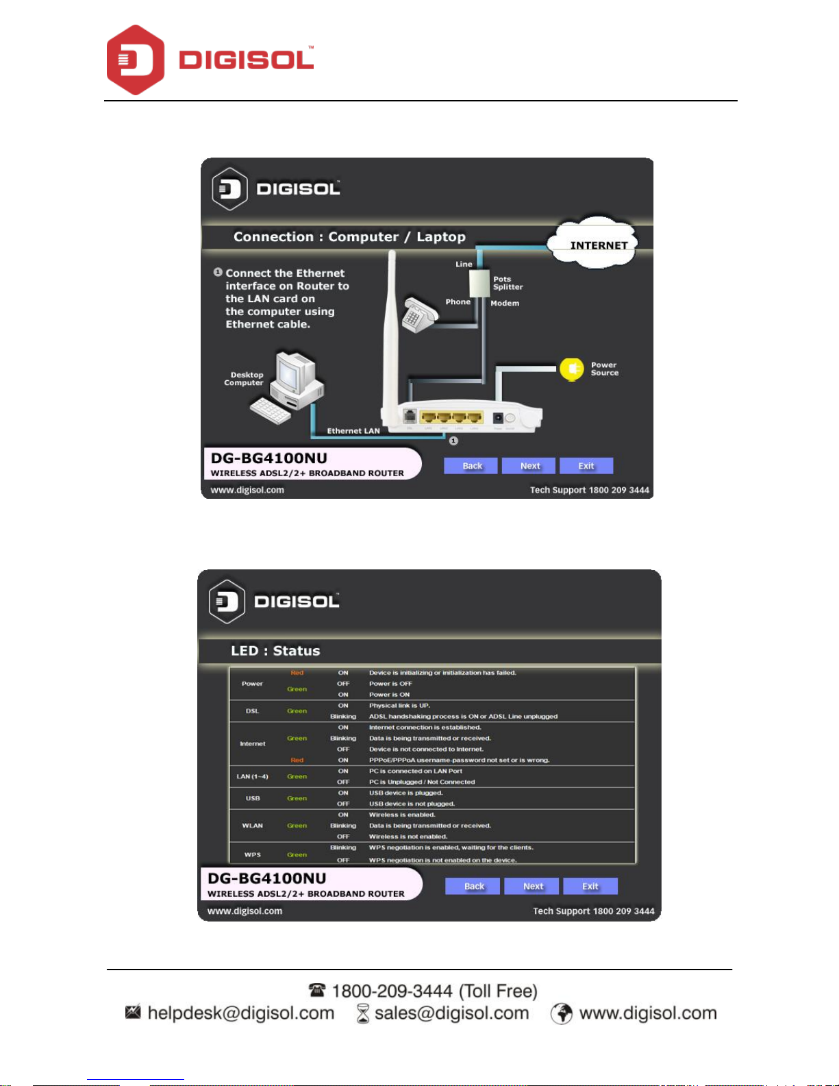
1.4 LEDs and Interfaces
Top Panel
The following table describes the LEDs of the device.
LEDs
Color
Status
Description
Power
Red
On
Dev ice is initializing or initialization has failed.
Off
Power is off.
Green
On
Power is on.
DSL
Green
On
Physical link is up
Blinking
ADSL handshaking process is on or ADSL line
unplugged.
Internet
Green
On
Internet connection is established.
Blinking
Data is being transmitted or receiv ed.
Off
Dev ice is not connected to internet.
Red
On
PPPoE/PPPoA username-password not set or
wrong.
LAN
1/2/3/4
Green
On
PC is connected to LAN port
Off
PC is unplugged/not connected.
USB
Green
On
USB device is plugged.
Off
USB device is not plugged.
Page 9

DG-BG4100NU User Manual
9
WLAN
Green
On
Wireless is enabled.
Blinking
Data is being transmitted or receiv ed.
Off
Wireless is not enabled.
WPS
Green
Blinking
WPS negotiation is enabled waiting for the
clients.
Off
WPS negotiation is not enabled on the dev ice.
Page 10
DG-BG4100NU User Manual
10
Rear Panel
The f ollowing table describes the interfaces of the device.
Item
Description
Antenna
One 5dBi fixed dipole antenna.
DSL
RJ-11 interface, for connecting to the ADSL interface or a splitter using
a telephone cable.
LAN4/3/2/1
RJ-45 interface, for connecting to the Ethernet interface of a computer
or the Ethernet dev ices through an Ethernet cable/LAN Cable.
Power
Power interf ace, for connecting to the power adapter.
ON / OFF
Power switch, to power on or power off the device.
Page 11
DG-BG4100NU User Manual
11
Side Panel
Item
Description
USB
To connect USB 3G Dongle or USB Mass Storage.
Reset
Reset to the f actory default configuration. Keep the device powered
on, and insert a pin into the reset hole for 3 seconds, then release it.
The device will reset to the factory default configuration.
Page 12

DG-BG4100NU User Manual
12
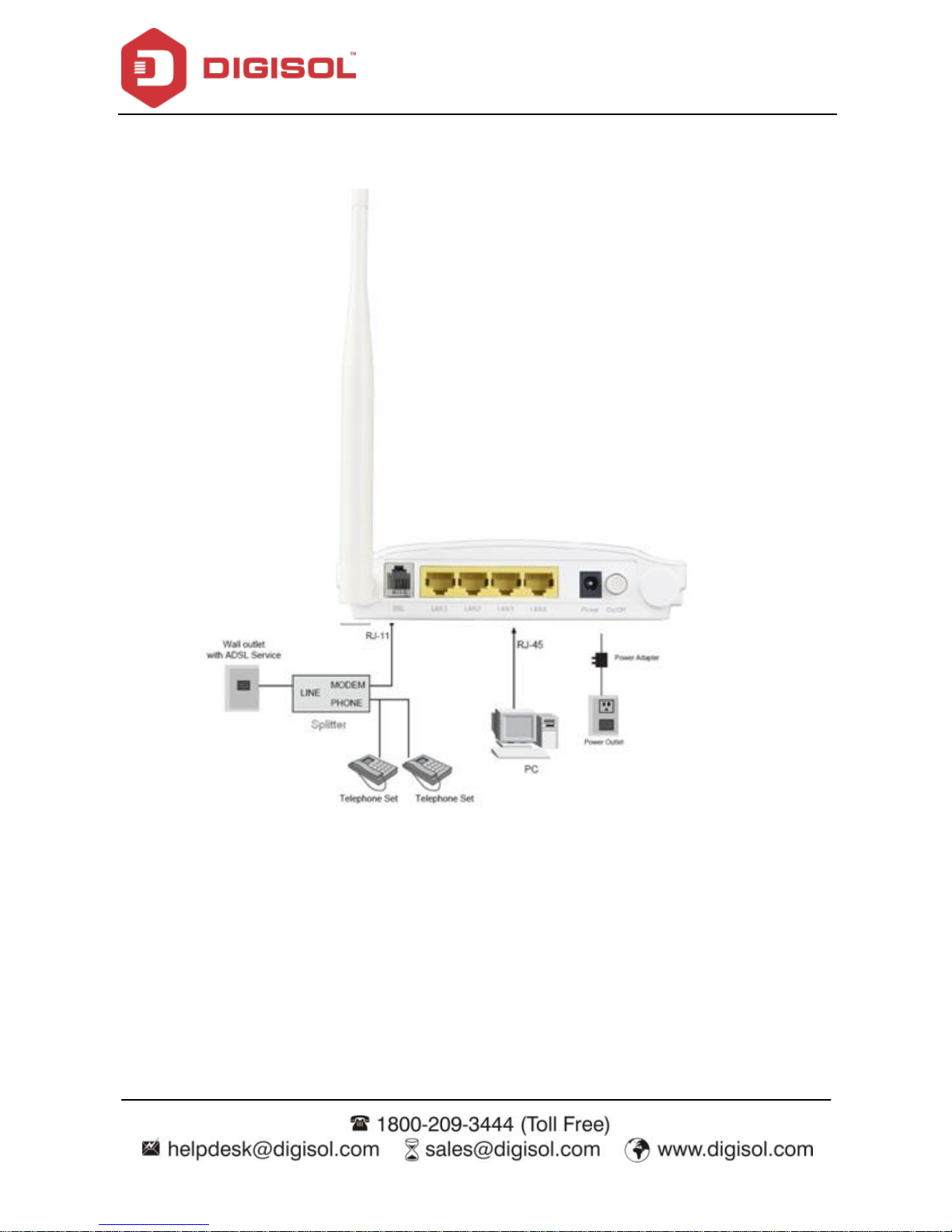
2 Hardware Installation
Connect the ADSL interface of the device and the router interf ace of the splitter
through a telephone cable. Connect the phone to the Phone interface of the splitter
through a telephone cable. Connect the incoming line to the Line interface of the
splitter.
The splitter has three interfaces:
Line: Connect to a wall phone jack (RJ-11 jack).
Modem: Connect to the ADSL jack of the device.
Phone: Connect to a telephone set.
Connect the LAN interface of the device to the network card of the PC through an
Ethernet cable (MDI/MDIX).
Note: Use twisted-pair cables to connect to the hub or switch.
Plug one end of the power adapter to the wall outlet and the other end to the
Power interface of the device.
Page 13
DG-BG4100NU User Manual
13
The following f igure shows the application diagram f or the connection of the router, PC, splitter
and the telephone sets.
Page 14
DG-BG4100NU User Manual
14
3 Software Installation
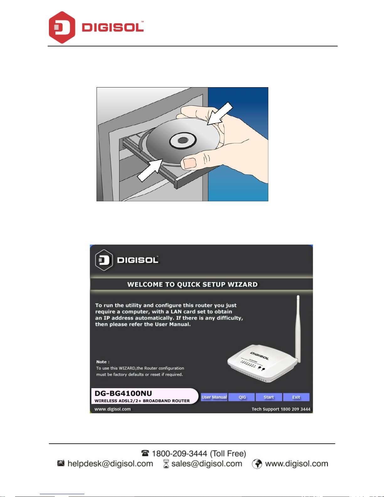
Insert the Setup CD into your CD-ROM drive of notebook/desktop computer.
Explore the CD and execute the ‚India_autorun.EXE‛ file. Screen given below
will be displayed. Click‘Start’to continue.
Page 15
DG-BG4100NU User Manual
15
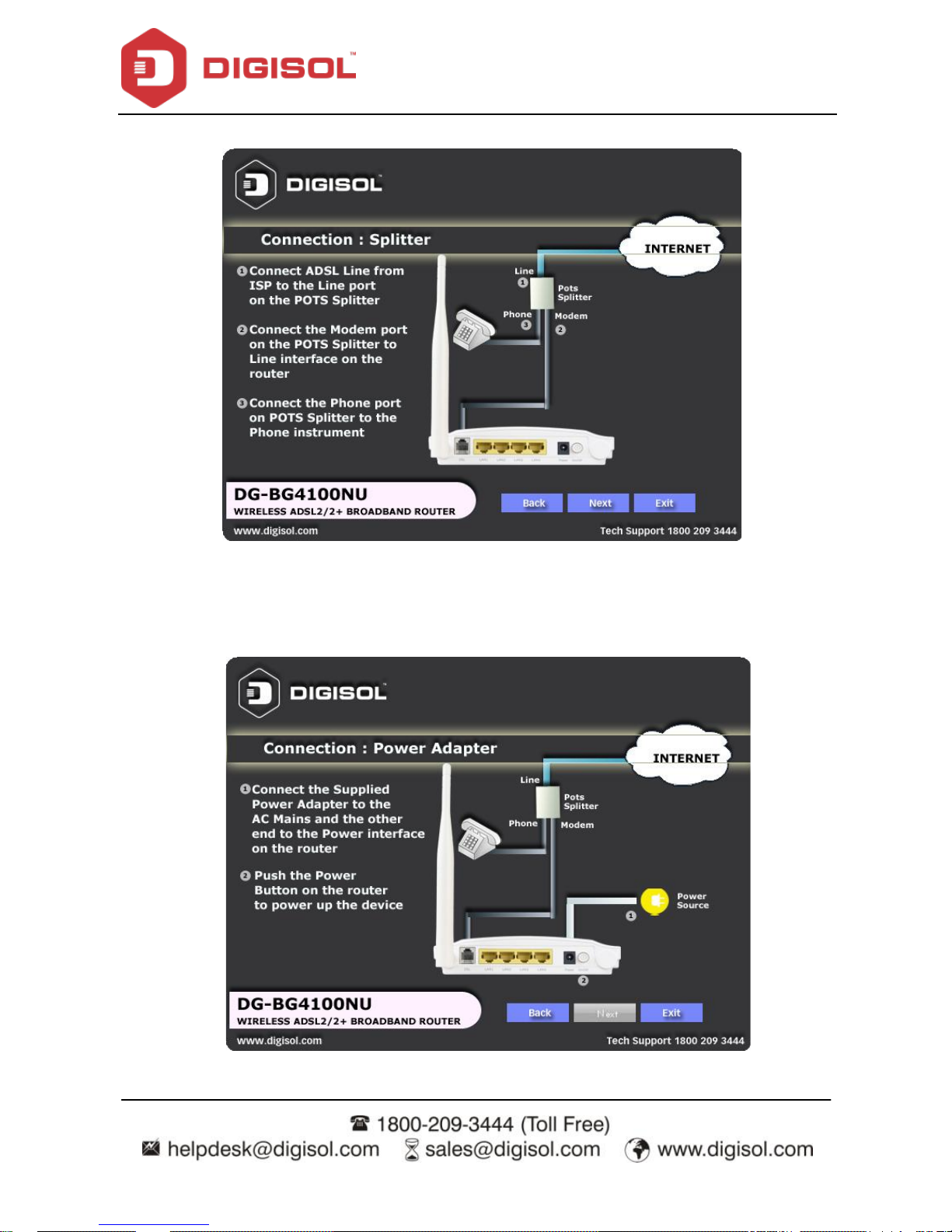
Connect the ADSL line and the phone line to the router. Click ‗Next’.
Connect the power adapter to the AC Mains and the other end to the power
interface on the router. Push the power button on the router to power up the
dev ice. Click ‗Next‘.
Page 16
DG-BG4100NU User Manual
16
Connect the Ethernet interf ace on the router to the LAN card on the computer
using the Ethernet cable. Click ‗Next’.
After powering up the router, verify the status of the LED indicators on the front
panel of the router. Click ‗Next’.
Page 17
DG-BG4100NU User Manual
17
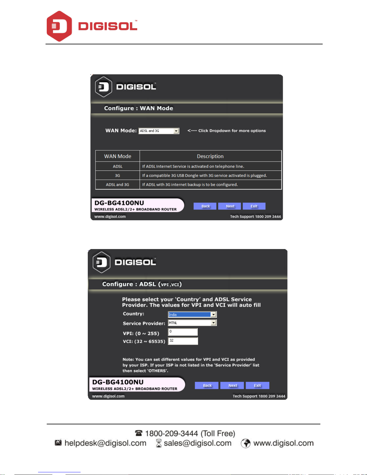
Below as shown please select the ―WAN Mode‛type.
Suppose y ou select ―ADSL and 3G‖ option to setup 3G f ailov er click ―Next‖.
Please select your ‗Country‘ and ADSL serv ice provider. VPI and VCI values
will auto fill.
Page 18
DG-BG4100NU User Manual
18
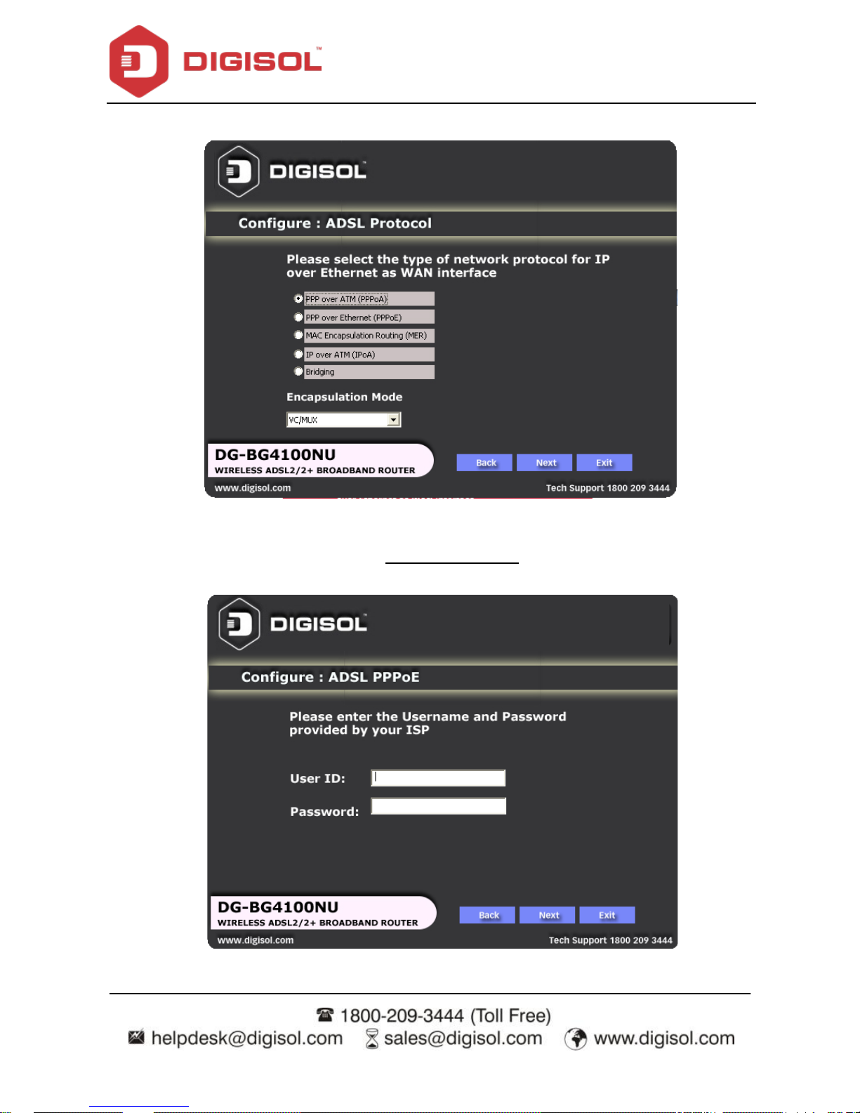
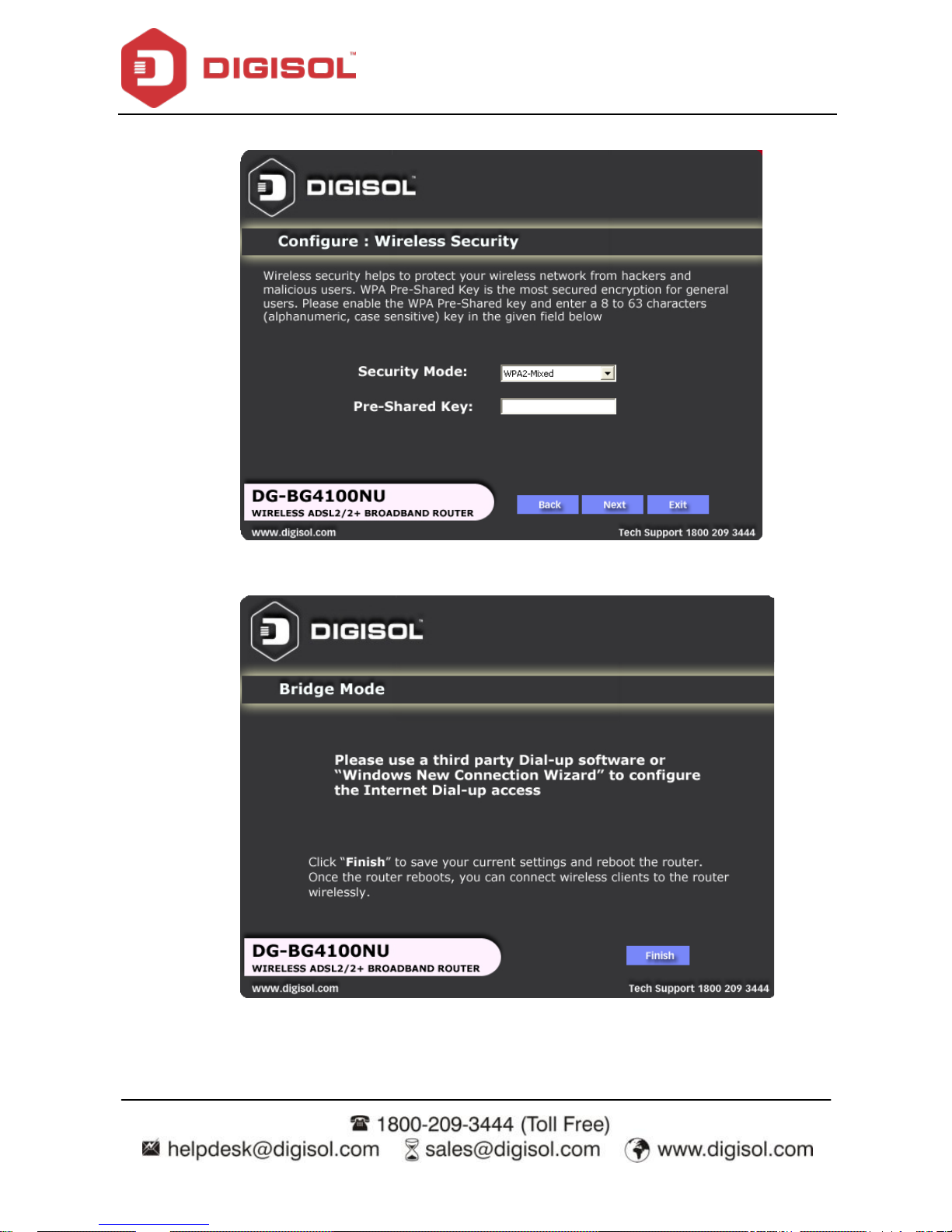
Select the network protocol for WAN interf ace. Click ‗Next‘.
All the utility installation steps till here are the common steps to be followed for the modes.
Following are the steps f or configuring PPPoE connection:
Enter the username and password provided by your ISP. Click ‗Next’.
Page 19
DG-BG4100NU User Manual
19
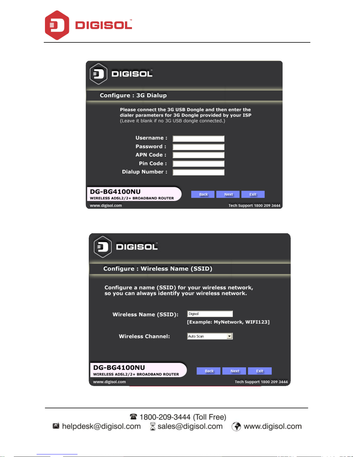
Conf igure the 3G Dialup parameters and click‚Next‛
Conf igure a wireless name (SSID) for your router. Click ‗Next’.
Page 20
DG-BG4100NU User Manual
20
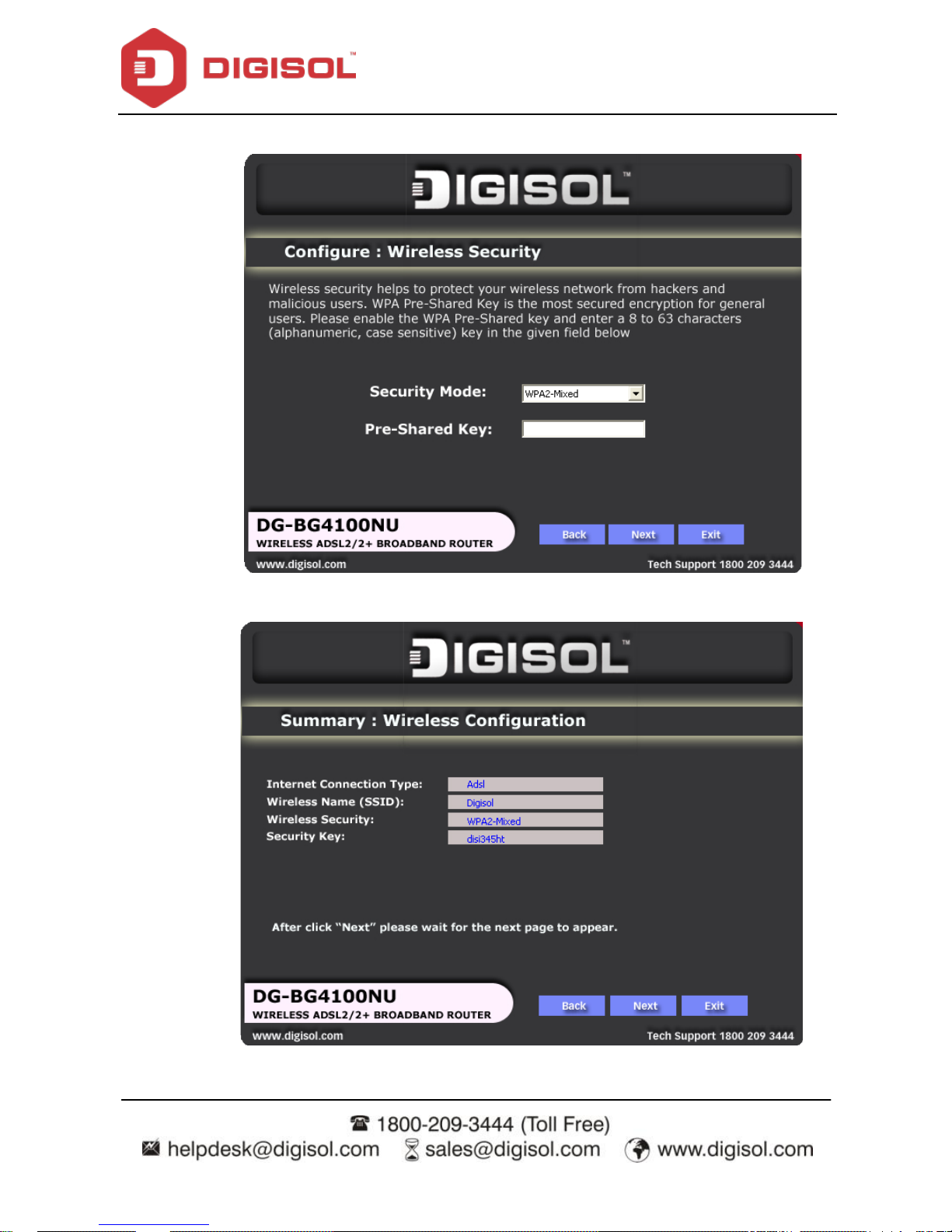
Conf igure the wireless security. Click ‗Next’.
The next screen is a summary of the wireless settings of the router.
Page 21
DG-BG4100NU User Manual
21
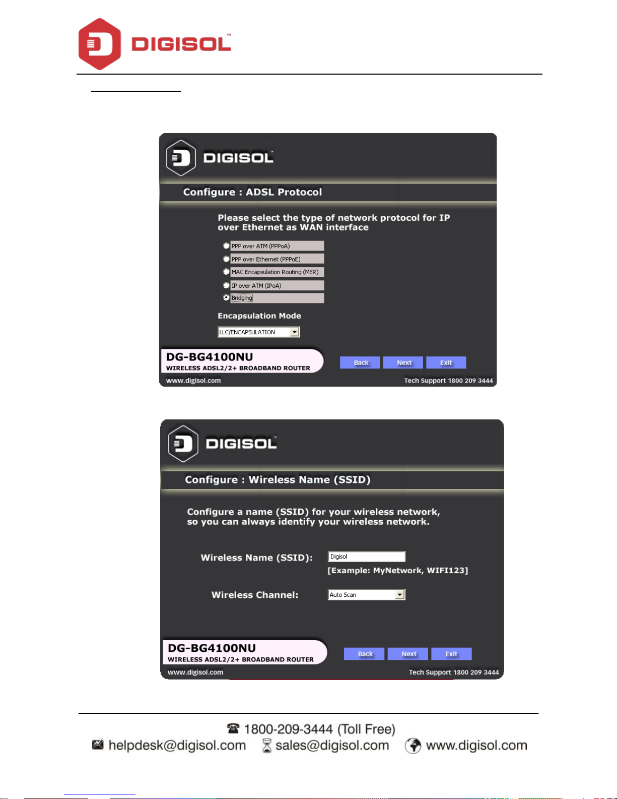
Click on ‘Next’, the following screen will appear.
Once the connection is established, the router connection status will appear.
Page 22
DG-BG4100NU User Manual
22
Bridging Mode:
To configure the router in the bridge mode select‚Bridging‛option. Click
‗Next’.
Conf igure a wireless name (SSID) for your router. Click ‗Next’.
Page 23
DG-BG4100NU User Manual
23
Conf igure the wireless security.
Click on ‗Next‘ the following screen will appear.
Click on ‗Finish‘ to complete the configuration of the router in Bridge mode.
Page 24
DG-BG4100NU User Manual
24
4 About the Web Configuration
This section describes how to configure the router by using the Web-based configuration
utility.
4.1 Access the Router
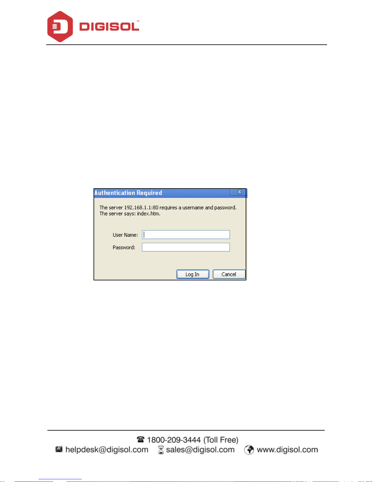
The following is the detailed description of accessing the router for the first time.
Open the Internet Explorer (IE) browser and enter http://192.168.1.1.
In the Login page that is display ed, enter the username and password.
The username and password of the super user are admin and admin.
The username and password of the common user are user and user.
If you log in as a super user, the page shown in the following f igure appears. You can check,
conf igure and modify all the settings.
Page 25
DG-BG4100NU User Manual
25
If you log in as a common user, you can check the status of the router, but cannot
conf igure/modify most of the settings.
Note: In the Web configuration page, you can click Apply Changes to save the settings.
4.2 Wizard
When subscribing to a broadband serv ice, you should be aware of the method by which you
are connected to the Internet. Your physical WAN device can be PPP, ADSL or both. The
technical information about the properties of your Internet connection is provided by your
Internet Service Provider (ISP). For example, your ISP should inform you whether you are
connected to the Internet using a static or dynamic IP address and the protocol that you use
to communicate on the Internet.
In the nav igation bar, choose Wizard. The page shown in the following f igure appears. The
Wizard page guides fast and accurate configuration of the Internet connection and other
important parameters. The following sections describe these various configuration
Page 26
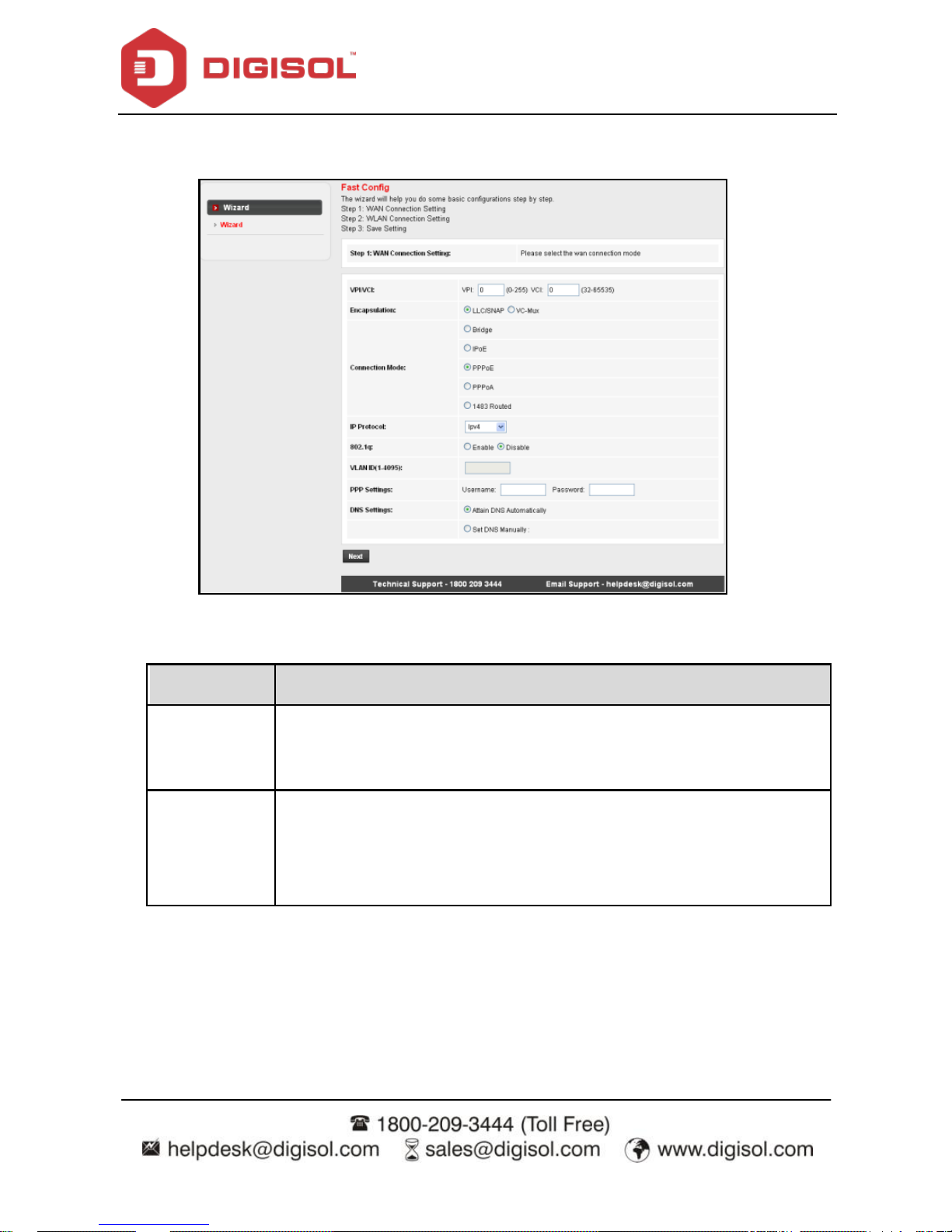
DG-BG4100NU User Manual
26
parameters. Whether you configure these parameters or use the def ault ones, click NEXT to
enable y our Internet connection.
The following table describes the parameters in this page:
Field
Description
VPI
Virtual path identifier (VPI) is the virtual path between two points in an
ATM network. Its valid value is in the range of 0 to 255. Enter the correct
VPI provided by your ISP. By default, VPI is set to 0.
VCI
Virtual channel identifier (VCI) is the virtual channel between two points
in an ATM network. Its valid value is in the range of 32 to 65535. (0 to 31
is reserved f or local management of ATM traffic) Enter the correct VCI
provided by your ISP. By default, VCI is set to 35.
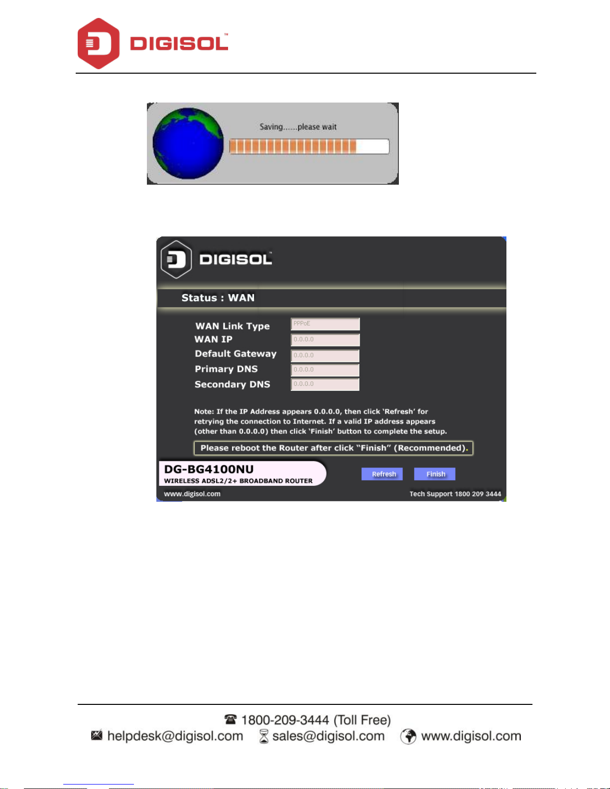
After the setting is done, click Next, the page as shown in the following figure appears.
There are f ive WAN connection types: PPP ov er ATM (PPPoA), PPP over Ethernet (PPPoE),
and 1483 Routed. The following sections below describe them respectively.
Page 27

DG-BG4100NU User Manual
27
PPPoE/PPPoA
In the Connection Type page, set the WAN connection type to PPP over Ethernet (PPPoE),
the encapsulation mode to LLC/SNAP.
The following table describes the parameters in this page:
Field
Description
Connection Mode
There are three WAN connection types: PPP over
ATM (PPPoA), PPP ov er Ethernet (PPPoE) and 1483
Page 28
DG-BG4100NU User Manual
28
Field
Description
Routed. In this example, the connection type is set to
PPPoE.
Encapsulation Mode
You can select LLC/SNAP or VC-Mux. In this example,
the encapsulation mode is set to LLC/SNAP.
IP Protocol
Select the IMP protocol: IPv4, IPv6 or IPv4/IPv 6.
802.1q
You can enable or disable 802.1q
VLAN ID (1-4095)
Enter the VLAN ID here. The valid range is 1-4095.
PPP Settings
Enter the username and password.
DNS Settings
Select the DNS settings.
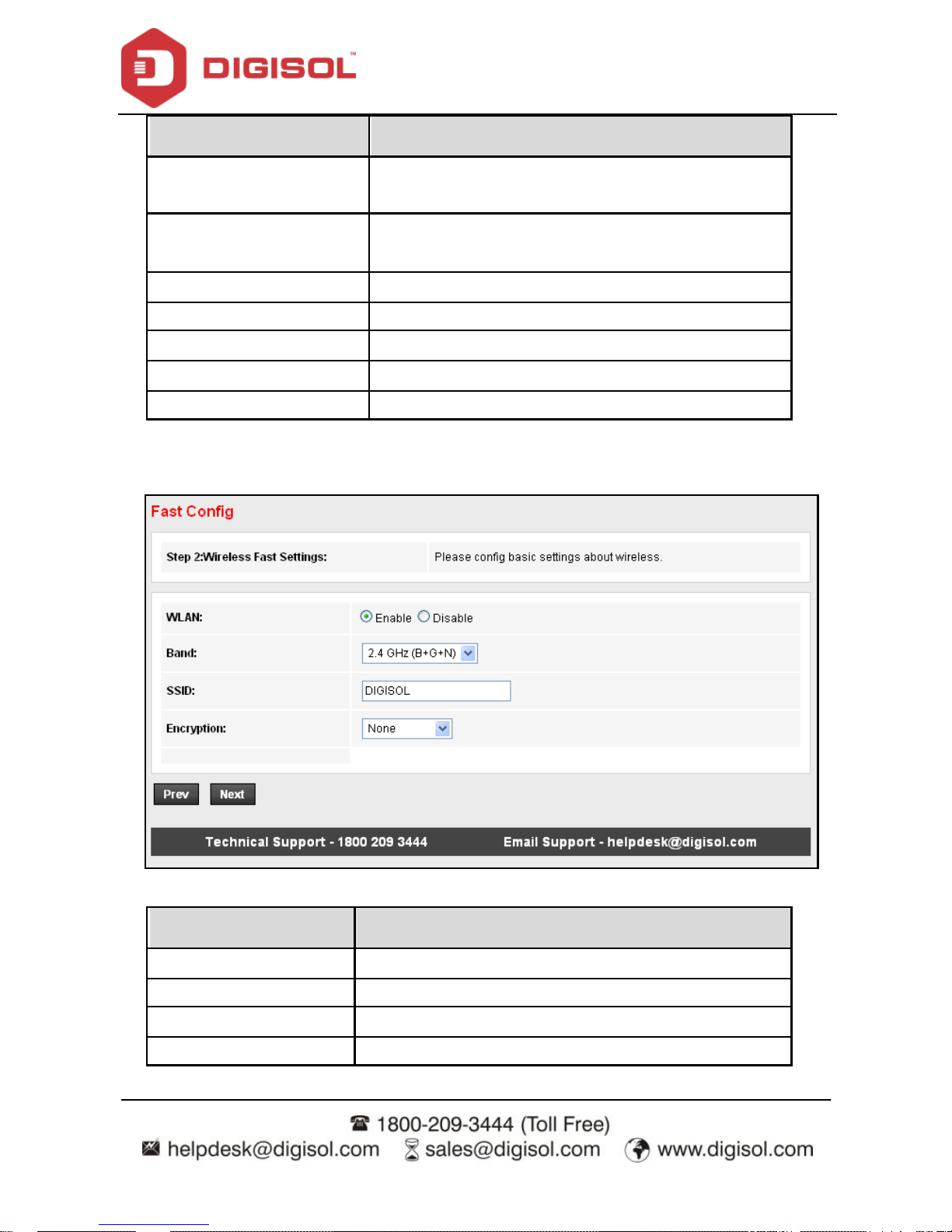
After the settings are done, click Next, the page as shown in the following figure appears.
The following table describes the parameters in this page:
Field
Description
WLAN
You can enable or disable the WLAN.
Band
Here select the appropriate band f orm the list.
SSID
Enter the SSID.
Encry ption
Select the encry ption from the list.
Page 29
DG-BG4100NU User Manual
29
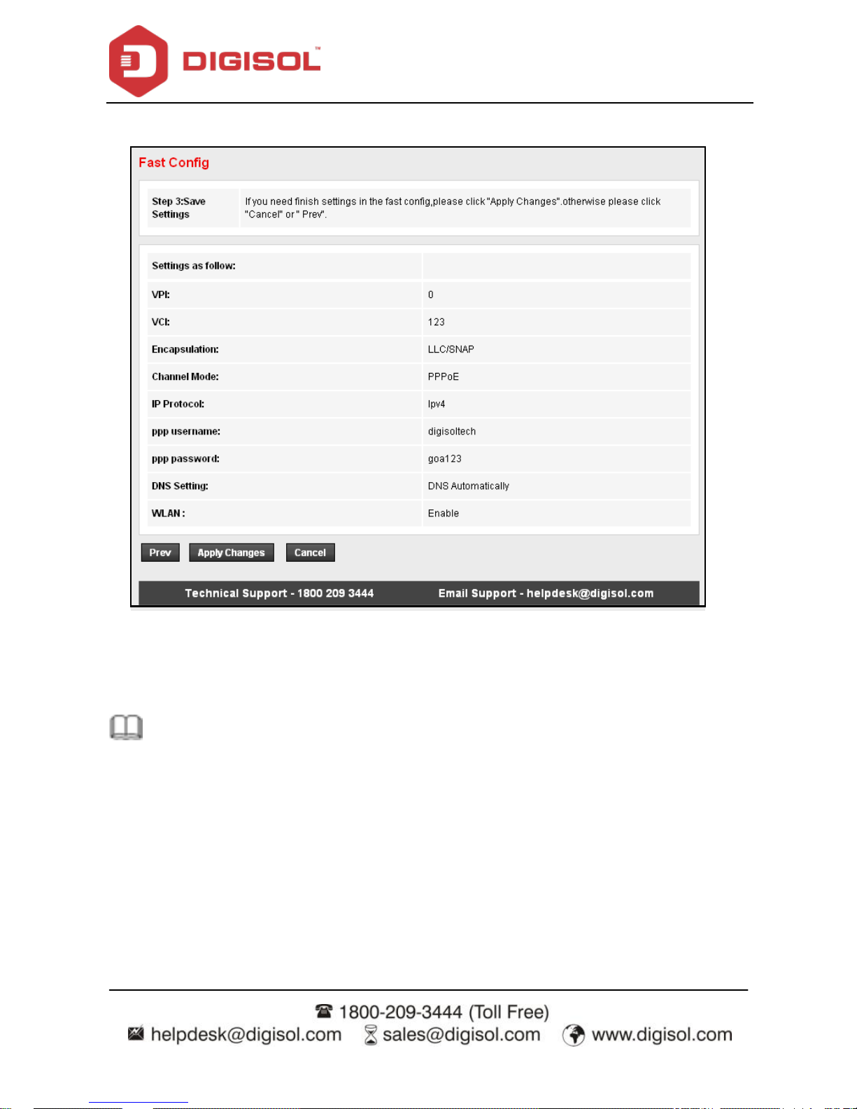
After the settings are done, click Next, the page as shown in the following figure appears.
If y ou need finish settings in the fast config, please click "Apply Changes" otherwise please
click "Cancel" or "Prev".
Note: If the WAN connection type is set to PPPoA, the parameters of the WAN
connection type are the same as that of PPPoE.
Page 30

DG-BG4100NU User Manual
30
1483 Routed
In the Connection Ty pe page, set the WAN connection type to 1483 Routed, the
encapsulation mode to LLC/SNAP.
Page 31

DG-BG4100NU User Manual
31
After the settings are done, click Next, the page as shown in the following figure appears.
For subsequent configuration, refer to the description in the above section PPPoE/PPPoA.
Page 32

DG-BG4100NU User Manual
32
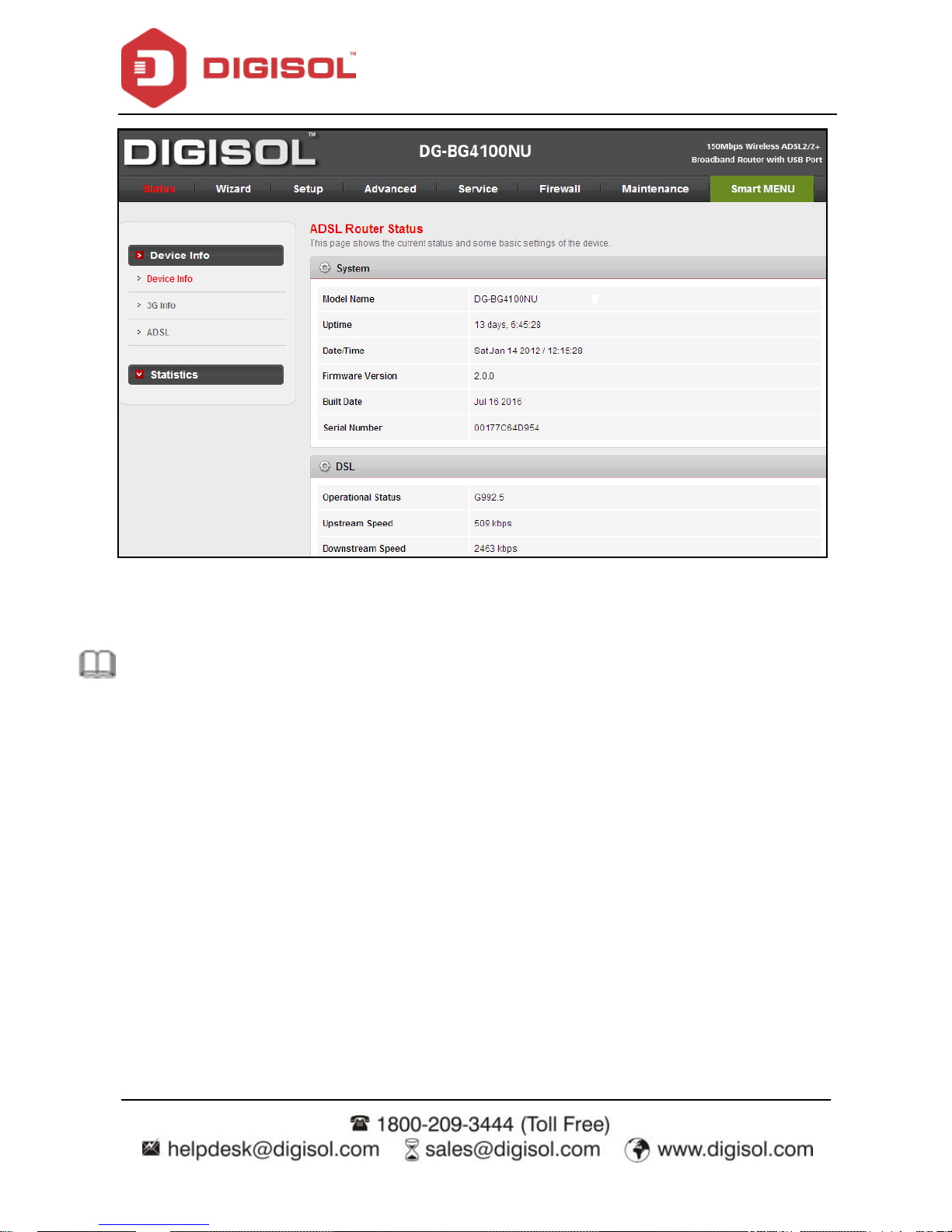
4.3 Status
In the nav igation bar, choose Status. The Status page that is display ed contains: Device Info,
3G Inf o and ADSL.
Device Info
Choose Status > Device Info. The page that is displayed shows the current status and some
basic settings of the router, such as firmware version, upstream speed, downstream speed,
LAN status, DNS status, ADSL WAN interfaces etc.
Page 33

DG-BG4100NU User Manual
33
3G Info
Choose Status > 3G Info. This page shows the Signal strength, Connection status, SIM card
status, IP address details of 3G etc.
Page 34

DG-BG4100NU User Manual
34
ADSL
This page shows the settings of the ADSL Router.
Statistics
Choose Status > Statistics.
Page 35

DG-BG4100NU User Manual
35
4.3.1.1 Statistics
Click Statistics in the left pane. The page shown in the f ollowing figure appears. In this page,
you can view the statistics of each network port.
Page 36

DG-BG4100NU User Manual
36
4.4 Setup
In the navigation bar, click Network. The Network page that is displayed contains WAN,
LAN and Wireless.
WAN
Choose Network > WAN. The WAN page that is displayed contains WAN, 3G, Auto PVC,
ATM Settings and ADSL Settings.
Page 37

DG-BG4100NU User Manual
37
4.4.1.1 WAN
Click WAN in the left pane, the page shown in the following f igure appears. In this page, you
can configure WAN interface of your router.
Page 38

DG-BG4100NU User Manual
38
The following table describes the parameters of this page:
Field
Description
WAN physical type: Ethernet
WAN (Port-LAN1)
When this option is selected the unit will auto reboot.
Def ault Route Selection
You can select Auto or Specified.
VPI
The virtual path between two points in an ATM network,
ranging f rom 0 to 255.
VCI
The virtual channel between two points in an ATM network,
ranging from 32 to 65535 (1 to 31 are reserved for known
protocols)
Encapsulation
You can choose LLC and VC-Mux.
Channel Mode
You can choose PPPoE, PPPoA and 1483 Routed.
Enable NAPT
Select it to enable Network Address Port Translation (NAPT)
function. If you do not select it and you want to access the
Internet normally, you must add a route on the uplink
equipment. Otherwise, the access to the Internet f ails.
Normally, it is enabled.
Enable IGMP
You can enable or disable Internet Group Management
Protocol (IGMP) function.
PPP Settings
User Name
Enter the correct user name for PPP dial-up, which is provided
by your ISP.
Password
Enter the correct password for PPP dial-up, which is prov ided
by your ISP.
Type
You can choose Continuous, Connect on Demand, or Manual.
Idle Time (min)
If set the type to Connect on Demand, you need to enter the
idle timeout time. Within the preset minutes, if the router does
not detect the flow of the user continuously, the router
automatically disconnects the PPPoE connection.
WAN IP Settings
Type
You can choose Fixed IP or DHCP.
Page 39

DG-BG4100NU User Manual
39
If selected Fixed IP, you should enter the local IP address,
remote IP address and subnet mask.
If selected DHCP, the router is a DHCP client, the WAN IP
address is assigned by the remote DHCP server.
Local IP Address
Enter the IP address of WAN interface provided by your ISP.
Remote IP Address
Enter the remote IP address.
Net mask
Enter the subnet mask of the local IP address.
Unnumbered
Select this checkbox to enable IP unnumbered function.
Def ault Route
Enable/Disable the default route.
Add
After conf iguring the parameters of this page, click it to add a
new PVC into the Current ATM VC Table.
Modify
Select PVC in the Current ATM VC Table, then modify the
parameters of this PVC. After finishing, click it to apply the
settings of this PVC.
Delete
Select PVC in the Current ATM VC Table, then delete the PVC.
Reset
Click reset to undo the settings entered in this page and retain
them to default settings.
Current ATM VC Table
This table shows the existing PVCs. It shows the interface
name, channel mode, VPI/VCI, encapsulation mode, local IP
address, remote IP address and other information. The
maximum item of this table is eight.
Page 40

DG-BG4100NU User Manual
40
4.4.1.2 3G
This page is used to configure the parameters for your 3G network access.
Page 41

DG-BG4100NU User Manual
41
Field
Description
3G WAN
(Enable/Disable)
Selection will Enable or Disable 3G WAN.
Pincode
Enter the Pincode – Check with 3G Service provider.
APN
Enter the APN - Check with 3G Service provider.
Dial Number
Enter the dial number eg: *99#, #777 etc as per ISP.
Username
Enter username – Check with 3G service prov ider.
Password
Enter password – Check with 3G service provider.
Connection type
Persistent means Automatic dial & Manual means manual dial.
NAPT
WAN IP/Port sharing (Network Address Port Translation)
Def ault Route
Enable or Disable Def ault route. Router will select the default route
to internet.
MTU
Set as per 3G Serv ice provider (Do not modify).
IP Type
Select the IMP type: IPv4, IPv6 or IPv4/IPv6.
3G to wired switch
time
Set the switch over time in seconds.
Note: Kindly refer to the 3G USB compatibility list uploaded on the website.
Page 42

DG-BG4100NU User Manual
42
4.4.1.3 Auto PVC
Click Auto PVC in the left pane, page shown in the following figure appears. In this page, you
can get PVC automatically through detecting function, and add or delete the PVC that you
want or do not want.
Page 43

DG-BG4100NU User Manual
43
4.4.1.4 ATM Settings
Click ATM Settings in the left pane, the page shown in the following f igure appears. In this
page, you can configure the parameters of the ATM, including VPI, VCI, QoS, PCR, CDVT,
SCR and MBS.
The following table describes the parameters of this page:
Field
Description
VPI
The virtual path identif ier of the ATM PVC.
VCI
The virtual channel identif ier of the ATM PVC.
QoS
The QoS category of the PVC. You can choose UBR, CBR,
rt-VBR or nrt-VBR.
PCR
Peak cell rate (PCR) is the maximum rate at which cells can
be transmitted along a connection in the ATM network. Its
value ranges from 1 to 65535.
CDVT
Cell delay variation tolerance (CDVT) is the amount of delay
permitted between ATM cells (in microseconds). Its value
ranges from 0 to 4294967295.
SCR
Sustained cell rate (SCR) is the maximum rate that traffic can
Page 44

DG-BG4100NU User Manual
44
pass over PVC without the risk of cell loss. Its v alue ranges
from 0 to 65535.
MBS
Maximum burst size (MBS) is the maximum number of cells
that can be transmitted at the PCR. Its value ranges from 0 to
65535.
4.4.1.5 ADSL Settings
Click ADSL Settings in the left pane, the page shown in the following f igure appears. In this
page, you can select the ADSL modulation. Mostly, try to retain the factory default settings.
The router supports these modulations: G.Lite, G.Dmt, T1.413, ADSL2 and ADSL2+. The
router negotiates the modulation modes with the DSLAM.
LAN
Choose Network > LAN. The LAN page that is displayed contains LAN IP, DHCP and DHCP
Static IP.
Page 45

DG-BG4100NU User Manual
45
4.4.1.6 LAN
Click LAN IP in the left pane, the page shown in the following figure appears.
In this page, you can change the IP address of the router. The def ault IP address is
192.168.1.1, which is the priv ate IP address of the router.
Page 46

DG-BG4100NU User Manual
46
The following table describes the parameters of this page:
Field
Description
IP Address
Enter the IP address of LAN interface. It is recommended to use
an address from a block that is reserv ed for private use. This
address block for example is 192.168.1.1 - 192.168.1.254.
Subnet Mask
Enter the subnet mask of LAN interface. The range of subnet
mask is f rom 255.255.0.0 - 255.255.255.254.
Secondary IP
Select it to enable the secondary LAN IP address. The two LAN
IP addresses must be in different networks.
IGMP Snooping
When IGMP snooping is enabled, only hosts that belong to the
group receive the multicast packets. If a host is deleted from the
group, the host cannot receive the multicast packets any more.
MAC Address
Control
It is the access control based on MAC address. Select it, and the
host whose MAC address is listed in the Current Allowed MAC
Address table can access the router.
Add
Enter MAC address and then click it to add a new MAC address.
Current allowed
MAC address table
All the allowed MAC addresses added will be listed here.
Page 47

DG-BG4100NU User Manual
47
4.4.1.7 DHCP
Dynamic Host Configuration Protocol (DHCP) allows the individual PC to obtain the TCP/IP
conf iguration from the centralized DHCP server. You can configure this router as a DHCP
serv er or disable it. The DHCP serv er can assign IP address, IP default gateway and DNS
serv er to DHCP clients. This router can also act as a DHCP server (DHCP Relay ) where it
relays IP address assignment f rom an actual real DHCP server to clients. You can enable or
disable DHCP server.
Click DHCP in the left pane, the page shown in the following figure appears.
Page 48

DG-BG4100NU User Manual
48
The following table describes the parameters of this page:
Field
Description
DHCP Mode
If set to DHCP Server, the router can assign IP addresses, IP default
gateway and DNS Servers to the host in Windows95, Windows NT and
other operation systems that support the DHCP client.
IP Pool Range
It specifies the first and the last IP address in the IP address pool. The
router assigns IP address that is in the IP pool range to the host.
Show Client
Click it, the Active DHCP Client Table appears. It shows IP addresses
assigned to clients.
Subnet Mask
Enter the subnet mask here.
Def ault Gateway
Enter the def ault gateway of the IP address pool.
Max Lease Time
The lease time determines the period that the host retains the assigned
IP addresses bef ore the IP addresses change.
Domain Name
Enter the domain name if you know. If you leav e this blank, the domain
name obtained by DHCP from the ISP is used. You must enter host
name (system name) on each indiv idual PC. The domain name can be
assigned f rom the router through the DHCP server.
DNS Serv ers
You can conf igure the DNS server ip addresses for DNS Relay.
Set VendorClass
IP Range
Click it, the Device IP Range Table appears. You can configure the IP
address range based on the dev ice type.
Page 49

DG-BG4100NU User Manual
49
Click Show Client in the DHCP Mode page, the page shown in the following f igure appears.
You can view the IP address assigned to each DHCP client.
The following table describes the parameters and buttons in this page:
Field
Description
IP Address
It displays the IP address assigned to the DHCP client from the
router.
MAC Address
It display s the MAC address of the DHCP client.Each Ethernet
device has a unique MAC address. The MAC address is
assigned at the factory and it consists of six pairs of
hexadecimal characters, for example, 00-17-7C-00-02-12.
Page 50

DG-BG4100NU User Manual
50
Click Set VendorClass IP Range in the DHCP Mode page, the page as shown in the following
figure appears. In this page, y ou can conf igure the IP address range based on the device
type.
In the DHCP Mode f ield, choose None. The page shown in the following f igure appears.
Page 51

DG-BG4100NU User Manual
51
In the DHCP Mode field, choose DHCP Relay. The page shown in the following f igure
appears.
The following table describes the parameters and buttons of this page:
Field
Description
DHCP Mode
If set to DHCP Relay, the router acts a DHCP Server and relays
the DHCP requests and responses between the remote server and
the client.
Relay Serv er
Enter the DHCP server address prov ided by your ISP.
Apply Changes
Click it to save the settings of this page.
Reset
Click it to refresh this page.
Page 52

DG-BG4100NU User Manual
52
4.4.1.8 DHCP Static
Click DHCP Static IP in the left pane, the page shown in the following figure appears. You
can assign the IP addresses on the LAN to the specific individual PCs based on their MAC
address.
The following table describes the parameters and buttons of this page:
Field
Description
IP Address
Enter the specif ied IP address in the IP pool range, which is
assigned to the host.
MAC Address
Enter the MAC address of a host on the LAN.
Add
After entering the IP address and MAC address, click it. A
row will be added in the DHCP Static IP Table.
Delete Selected
Select a row in the DHCP Static IP Table, then click it, this
row will be deleted.
Undo
Click it to refresh this page.
DHCP Static IP Table
It shows the assigned IP address based on the MAC
address.
Page 53

DG-BG4100NU User Manual
53
4.4.1.9 LAN IPv6
Click LAN IP in the left pane, the page shown in the following f igure appears. In this page,
you can change the IP address of the router. The def ault IP address is 192.168.1.1, which is
the private IP address of the router.
Page 54

DG-BG4100NU User Manual
54
The following table describes the RA parameters of this page.
Field
Description
Global Address
Specify the LAN global ipv 6 address, which may be assigned by ISP.
RA Setting
Enable
Enable or disable the Router Advertisement feature.
M Flag
Enable or disable the ―Managed address conf iguration‖ f lag in RA
packet.
O Flag
Enable or disable the ―Other conf iguration‖ flag in RA packet.
Max interval
The maximum time allowed between sending unsolicited multicast
Router Advertisements from the interf ace, in seconds.
Note: The Max Interval must not be less than 4 seconds and not
greater than 1800 seconds.
Min Interval
The minimum time allowed bet ween sending unsolicited multicast
Router Advertisements from the interf ace, in seconds.
Note: The Min Interval must not be less than 3 seconds and not
greater than 0.75 * Max Interval.
Prefix Mode
Specify the RA f eature prefix mode:
―Auto‖: The R A prefix will use Wan dhcp-pd pref ix. ―Manual‖: User will
specify the prefix Address, Length, Preferred time and Valid time.
ULA Enable
When enabled the f ollowing parameters appear:
RA DNS Enable
When enabled the f ollowing parameters appear:
DHCPv6 Setting
Page 55

DG-BG4100NU User Manual
55
Field
Description
DHCPv6 Mode
Specify the dhcpv6 serv er mode:
―None‖: Close dhcpv6 serv er.
―Manual‖: dhcpv 6 server is opened and user specif ies the dhcpv 6
serv er address pool and other parameters.
―Auto‖: dhcpv 6 server is opened and it can use Wan dhcp -pd prefix to
generate address pool.
IPv6 address suffix
pool
Type the IPv6 address suffix range for the DHCPv6 LAN clients
IPv6 DNS Mode
Type the IPv6 DNS address
Page 56

DG-BG4100NU User Manual
56
4.4.1.10 Wireless
Choose Setup > Wireless. The WLAN page that is displayed contains Basic, Security,
MBSSID, Access Control List, Advanced, WPS and WDS.
4.4.1.11 Basic
Choose Wireless > Basic and the following page appears. In this page, y ou can configure
the parameters for wireless LAN clients that may connect to the router.
Page 57

DG-BG4100NU User Manual
57
The following table describes the parameters of this page:
Field
Description
Band
Choose the working mode of the router. You can choose from
drop-down list.
Mode
Choose the network mode of the router, which varies according to
the software. By def ault, the network model of the router is AP.
SSID
The serv ice set identification (SSID) is a unique name to identify the
router in the wireless LAN. Wireless stations associating to the
router must have the same SSID. Enter a descriptive name that is
used when the wireless client is connecting to the router.
Channel Width
Options av ailable are 40 MHZ, 20 MHz and 40/20 MHz
Control Sideband
There are two sidebands upper and lower bands. The lower band
comprises of channel numbers 1-7. The upper band comprises of
channel numbers 5-11.
Channel Number
A channel is the radio frequency used by 802.11b/g/n wireless
devices. There are 11 channels (f rom 1 to 11) available depending
on the geographical area. When You may have a choice of channels
(for your region) you should use a different channel f rom an
adjacent AP to reduce the interf erence and degrading performance
occurs when radio signal from different APs overlap. Choose a
channel from the drop-down list box.
Radio Power (Percent)
You can choose the transmission power of the radio signal. The
default one is 100%. It is recommended to choose the def ault value
100%.
Show Active Clients
Click it to view the information of the wireless clients that are
connected to the router.
Apply Changes
Click it to apply the settings.
Page 58

DG-BG4100NU User Manual
58
4.4.1.12 Security
Choose Wireless > Security and the following page appears.
The following table describes the parameters of this page:
Field
Description
Encry ption
Conf igure the wireless encryption mode. You can choose
None, WEP, WPA (TKIP), WPA (AES), WPA2 (AES), WPA2
(TKIP) or WPA2 Mixed.
Wired equivalent privacy (WEP) encrypts data frames
before transmitting over the wireless network.
Wi-Fi protected access (WPA) is a subset of the
IEEE802.11i security specification draft.
WPA2 Mixed is the collection of WPA and WPA2
encry ption modes. The wireless client establishes the
connection between the router through WPA or WPA2.
Key differences between WPA and WEP are user
Page 59

DG-BG4100NU User Manual
59
authentication and improv ed data encryption.
WPA Authentication
Mode
Select Personal (Pre-Shared Key), enter the pre-shared
key in the Pre-Shared Key field.
Select Enterprise (RADIUS); enter the port, IP address and
password of the Radius serv er.
You need to enter the username and password provided by
the Radius server when the wireless client connects to the
router. If the encryption is set to WEP, the router uses
802.1x authentication, which is Radius authentication.
Select WEP encryption, as shown in the screen below and the following screen appears.
Page 60

DG-BG4100NU User Manual
60
4.4.1.13 MBSSID
Choose Wireless > MBSSID and the following page appears. In this page, you can configure
the multiple SSID on the access point.
It supports four virtual access points (VAPs). It is a unique name to identify the router in the
wireless LAN. Wireless stations associating to the router must have the same name. Enter a
descriptive name that is used when the wireless client connects to the router.
Page 61

DG-BG4100NU User Manual
61
4.4.1.14 Access Control List
Choose WLAN > Access Control List and the following page appears. In this page, you can
conf igure the access control of the wireless clients.
Choose Allow Listed as the access control mode to enable white list function. Only the
devices whose MAC addresses are listed in the Current Access Control List can access the
router.
Choose Deny Listed as the access control mode to enable black list function. The devices
whose MAC addresses are listed in the Current Access Control List are denied to access the
router.
Page 62

DG-BG4100NU User Manual
62
4.4.1.15 Advanced
Choose WLAN > Advanced and the following page appears. In this page, you can configure
the wireless advanced parameters. It is recommended to use the default parameters.
Note: The parameters in the Advanced link are modified by the professional
personnel, it is recommended to keep the default values.
The following table describes the parameters of this page:
Field
Description
Authentication type
Select the router operating in the open system or encryption
authentication. You can choose Open System, Shared Key, or
Auto.
In the open system, the wireless client can directly connect
Page 63

DG-BG4100NU User Manual
63
to the device.
In Shared key, the wireless client connects to the router
using the shared key.
The default is set to Auto, which allows either Open System
or Shared Key authentication to be used.
Fragment treshold
This value should remain at its def ault setting of 2346. It
specif ies the maximum size for a packet before data is
fragmented into multiple packets. If you experience a high
packet error rate, y ou may slightly increase the ―F ragment
Threshold‖ v alue within the value range of 256 to 2346. Setting
this value too low may result in poor network perf ormance. Only
minor modif ications of this value are recommended.
RTS Treshold
This v alue should remain at its default setting of 2347. If you
encounter inconsistent data flow, only minor modif ications are
recommended. If a network packet is smaller than the preset
―RTS thres hold‖ size, the RTS/CTS mechanism will n ot be
enabled.
Beacon Interval
The Beacon Interval value indicates the frequency interval of the
beacon. Enter a value between 20 and 1024.
DTIM Interv al
Data beacon proportion (transmission quantity indication). Its
value range is 1-255 and the default value is 100.
Data Rate
Choose the transmission rate of the wireless data.
You can choose Auto, 1 M, 2 M, 5.5 M, 11 M, 6 M, 9 M, 12 M, 18
M, 24 M, 36 M, 48 M, 54M, MSC0 ~ MSC15.
PreambleTy pe
Long Preamble: It means this card always uses long
preamble.
Short Preamble: It means this card can support short
preamble capability.
Broadcast SSID
Select whether the router broadcasts SSID or not. You can
select Enable or Disable.
Select Enable, the wireless client searches the router
through broadcasting SSID.
Select Disable to hide SSID, the wireless clients cannot find
Page 64

DG-BG4100NU User Manual
64
the SSID.
Relay Blocking
Wireless isolation. Once this field is Enabled, the wireless clients
that are connected to the router cannot intercommunicate.
Ethernet to Wireless
Blocking
Whether the wireless network can communicate with the
Ethernet network or not.
Wifi Multicast to
Unicast
Enable it to use unicast to transmit multicast packets.
Aggregation
It is applied when the destination end of all MPDU are for one
STA.
Short GI
It is not recommended to enable GI in obvious environment of
Multi-path eff ect.
Apply Changes
Click on this button to apply the settings.
4.4.1.16 WPS
Choose WLAN > WPS and the following page appears.
Page 65

DG-BG4100NU User Manual
65
There are two way s for the wireless client to establish connection with the router through
WPS. Click Regenerate PIN to generate a new PIN. In the wireless client tool, enter the PIN
which is generated by the router, start connection. The client will automatically establish the
connection with the router through the encry ption mode, and you need not enter the key. The
other way is the wireless client generates PIN. In the abov e figure, enter PIN of the wireless
client in the Client PIN Number field, then click Start PIN to establish the connection.
Note: The wireless client establishes the connection with the router through WPS
negotiation. The wireless client must support WPS.
4.4.1.17 WDS
Choose WLAN > WDS, and the following page appears. In this page you can enable
wireless distribution system (WDS) so that the router can communicate with another AP.
Page 66

DG-BG4100NU User Manual
66
The following table describes the parameters of this page:
Field
Description
Enable WDS
Check this box to enable WDS.
MAC Address
Wireless MAC address of the AP to be connected.
Comment
Add comment for the WDS AP.
Current WDS AP List
All the MAC addresses of the AP to be connected will be
listed here.
Page 67

DG-BG4100NU User Manual
67
4.5 Advanced
In the navigation bar, click Advanced. In the Adv anced page that is display ed contains
Routing, NAT, QoS, CWMP , Port Mapping and Others.
Routing
Choose Advance > Routing, and the page shown in the following figure appears. The page
that is displayed contains Static Route, IPv 6 Static Route and RIP.
4.5.1.1 Static Route
Click Static Route in the lef t pane, and the page shown in the following figure appears. This
page is used to conf igure the routing information. You can add or delete IP routes.
Page 68

DG-BG4100NU User Manual
68
The following table describes the parameters and buttons of this page:
Field
Description
Enable
Select it to use static IP routes.
Destination
Enter the IP address of the destination device.
Subnet Mask
Enter the subnet mask of the destination device.
Next Hop
Enter the IP address of the next hop in the IP route to the destination
device.
Metric
The metric cost f or the destination.
Interf ace
The interf ace for the specified route.
Add Route
Click it to add the new static route to the Static Route Table.
Update
Select a row in the Static Route Table and modify the parameters.
Then click it to save the settings temporarily.
Delete
Selected
Select a row in the Static Route Table and click it to delete the row.
Show Routes
Click it, the IP Route Table appears. You can view a list of destination
routes commonly accessed by your network.
Static Route
Table
A list of the previously conf igured static IP routes.
Click Show Routes, the page shown in the following f igure appears. The table shows a list of
destination routes commonly accessed by your network.
Page 69

DG-BG4100NU User Manual
69
4.5.1.2 IPv6 Static Route
Click IPv6 Static Route in the left pane, and the page shown in the following figure appears.
This page is used to configure the routing information. You can add or delete IP routes.
a)
The f ollowing table describes the parameters and buttons of this page.
Field
Description
Destination
Enter the IPv6 address of the destination device.
Prefix Length
Enter the prefix length of the IPv 6 address.
Next Hop
Enter the IP address of the next hop in the IPv6 route to the
destination address.
Interf ace
The interf ace for the specified route.
Add Route
Click it to add the new static route to the IPv6 Static Route Table.
Delete
Selected
Select a row in the IPv6 Static Route Table and click it to delete the
row.
Page 70

DG-BG4100NU User Manual
70
4.5.1.3 RIP
Click RIP in the lef t pane, the page shown in the following figure appears. If you are using this
device as a RIP-enabled router to communicate with others using Routing Information Protocol
(RIP), enable RIP. This page is used to select the interf aces on your devices that use RIP, and
the version of the protocol used.
The following table describes the parameters and buttons of this page:
Field
Description
RIP
Select Enable, the router communicates with other
RIP-enabled devices.
Apply
Click it to save the settings of this page.
Interf ace
Choose the router interf ace that uses RIP.
Receive Version
Choose the interface version that receives RIP messages. You
Page 71

DG-BG4100NU User Manual
71
can choose RIP1, RIP2 or Both.
Choose RIP1 indicates the router receives RIP v1 messages.
Choose RIP2 indicates the router receives RIP v2 messages.
Choose Both indicates the router receives RIP v 1 and RIP v2
messages.
Send Version
The working mode f or sending RIP messages. You can choose
RIP1 or RIP2.
Choose RIP1 indicates the router broadcasts RIP1 messages
only.
Choose RIP2 indicates the router multicasts RIP2 messages
only.
Add
Click it to add the RIP interface to the RIP Conf ig List.
Delete
Select a row in the RIP Config List and click it to delete the row.
Page 72

DG-BG4100NU User Manual
72
NAT
Choose Advanced > NAT, and the page shown in the following figure appears. The page
that is displayed contains Setup DMZ, Virtual Server, ALG, NAT Exclude IP, Port Trigger, FTP
ALG Port and NAT IP Mapping.
4.5.1.4 DMZ
Demilitarized Zone (DMZ) is used to prov ide Internet services without sacrificing
unauthorized access to its local private network. Typically, the DMZ host contains devices
accessible to Internet traff ic, such as web (HTTP) servers, FTP servers, SMTP (e-mail)
serv ers and DNS servers.
Click DMZ in the left pane, the page shown in the following figure appears.
The following steps describe how to conf igure manual DMZ.
Select Enable DMZ to enable this function.
Enter an IP address of the DMZ host.
Click Apply Changes to sav e the settings.
Note: DMZ when enabled, the remote access service of the Router web page will be disabled.
Page 73

DG-BG4100NU User Manual
73
As an alternative, you can use the port forwarding for that IP address/Port. Please contact technical
support for any technical help.
4.5.1.5 Virtual Server
Click Virtual Server in the lef t pane, and the page shown in the following figure appears.
The following table describes the parameters of this page.
Field
Description
Service Type
You can select the common service type, f or example, AUTH,
DNS or FTP. You can also def ine a service name.
If you select Usual Serv ice Name, the corresponding parameter
Page 74

DG-BG4100NU User Manual
74
has the def ault settings.
If you select User-defined Serv ice Name, you need to enter the
corresponding parameters.
Protocol
Choose the transport layer protocol that the service type uses.
You can choose TCP or UDP.
WAN Setting
You can choose Interface or IP Address.
WAN Interface
Choose the WAN interface that will apply virtual server.
WAN Port
Choose the access port on the WAN.
LAN Open Port
Enter the port number of the specified service type.
LAN IP Address
Enter the IP address of the v irtual server. It is in the same
network segment with LAN IP address of the router.
4.5.1.6 ALG
Click ALG in the left pane, and the page shown in the f ollowing figure appears. Choose the
NAT ALG and Pass-Through options, and then click Apply Changes.
Page 75

DG-BG4100NU User Manual
75
4.5.1.7 NAT Exclude IP
Click NAT Exclude IP in the left pane, and the page shown in the following figure appears.
In the page, you can configure some source IP addresses which use the purge route mode
when accessing internet through the specif ied interface.
Field
Description
IP range
Enter the IP address range, which do not require N AT
translation entries to be permitted by the router.
Page 76

DG-BG4100NU User Manual
76
4.5.1.8 Port Trigger
Click Port Trigger in the left pane, and the page shown in the following figure appears.
Page 77

DG-BG4100NU User Manual
77
Click the Usual Application Name drop-down menu to choose the application you want to
setup f or port triggering. When you have chosen an application the default Trigger settings
will populate the table below.
If the application you want to setup isn‘t listed, click the User-defined Application Name radio
button and ty pe in a name for the trigger in the Custom application field. Configure the Start
Match Port, End Match Port, Trigger Protocol, Start Relate Port, End Relate Port, Open
Protocol and NAT type settings f or the port trigger you want to conf igure.
When you have finished click the Apply changes button.
4.5.1.9 FTP ALG Port
Click FTP ALG Port in the left pane, the page shown in the following figure appears. The
common port for FTP connection is port 21, and a common ALG monitors the TCP port 21 to
ensure NAT pass-through of FTP. By enabling this function, when the FTP serv er connection
port is not port 21, the FTP ALG module will be informed to monitor other TCP ports to
ensure NAT pass-through of FTP.
The following table describes the parameters and buttons of this page:
Field
Description
FTP ALG port
Set an FTP ALG port.
Add Dest Ports
Add a port configuration.
Delete Selected DestPort
Delete a selected port configuration from the list.
Page 78

DG-BG4100NU User Manual
78
4.5.1.10 NAT IP Mapping
NAT is short for Network Address Translation. The Network Address Translation Settings
window allows you to share one WAN IP address for multiple computers on your LAN.
Click NAT IP Mapping in the lef t pane, the page shown in the following figure appears.
Entries in this table allow y ou to configure one IP pool for specified source IP address from
LAN, so one packet whose source IP is in range of the specif ied address will select one IP
address from the pool for NAT.
Page 79

DG-BG4100NU User Manual
79
QoS
Choose Advanced > QoS, and the page shown in the following figure appears. Entries in the
QoS Rule List are used to assign the precedence for each incoming packet based on
physical LAN port, TCP/UDP port number, source IP address, destination IP address and
other information.
Enable IP QoS and click Apply to enable IP QoS function.
Click add rule to add a new IP QoS rule. The screen shown below will appear.
Page 80

DG-BG4100NU User Manual
80
The following table describes the parameters and buttons of this page:
Field
Description
Source IP
The IP address of the source data packet.
Source Mask
The subnet mask of the source IP address.
Destination IP
The IP address of the destination data packet.
Destination
The subnet mask of the destination IP address.
Page 81

DG-BG4100NU User Manual
81
Mask
Source Port
The port of the source data packet.
Destination
Port
The port of the destination data packet.
Protocol
The protocol responds to the IP QoS rules. You can choose TCP,
UDP, or ICMP.
Phy Port
The LAN interface responds to the IP QoS rules.
IPP/DS Field
Select the IP packet header field type, Select IPP/TOS (IP
Precedence/Ty pe of Service) for def ining the IPP Range or Select
DSCP (Differentiated Services Code Point) for defining the DSCP
Range.
IP Precedence
Range
Select the IP Precedence range values for IPP/TOS.
Type of service
Select the type of service.
DSCP Range
Type the DSCP Value Range from 0~63.
Traffic Class
Range
Type the Traff ic Class range from 0~255.
802.1p
You can choose from 0 to 7.
Priority
The priority of the IP QoS rules. P0 is the highest priority and P3 is
the lowest.
Page 82

DG-BG4100NU User Manual
82
Traffic Shaping
Entries in this table are used for traffic control.
Click on ―Add‖, the following screen will appea r.
Page 83

DG-BG4100NU User Manual
83
The following table describes the parameters of this page:
Field
Description
Interf ace
Select the interf ace from the list.
Protocol
Select the below mentioned protocols from the list: None, ICMP, TCP,
UDP and TCP/UDP.
Src IP
The IP address of the source data packet.
Src Mask
The subnet mask of the source IP address.
Dst IP
The IP address of the destination data packet.
Dst Mask
The subnet mask of the destination IP address.
Src Port
The port of the source data packet.
Dst Port
The port of the destination data packet.
Up Floor
This value Should not be greater than Up Ceiling. This field defines
Guaranteed Upload bandwidth.
Up Ceiling
This f ield defines Maximum Upload bandwidth.
Down Floor
This v alue should not be greater than Down Ceiling. This field def ines
Guaranteed Download bandwidth.
Down Ceiling
This f ield defines Maximum Download bandwidth.
Page 84

DG-BG4100NU User Manual
84
CWMP
TR-069 is a protocol f or communication between a CPE and Auto-Configuration Server
(ACS).
Choose Advanced > CWMP, and the page shown in the f ollowing page appears. In this
page, you can configure the TR-069 CPE.
Page 85

DG-BG4100NU User Manual
85
The following table describes the parameters of this page:
Field
Description
ACS
URL
The URL of the auto-configuration server to connect to.
User Name
The user name for logging in to the ACS.
Password
The password for logging in to the ACS.
Periodic Inf orm Enable
Select Enable to periodically connect to the ACS to
check whether the conf iguration updates.
Periodic Inf orm Interval
Specify the amount of time between connections to
ACS.
Connection Request
User Name
The connection username prov ided by TR-069 service.
Password
The connection password provided by TR-069 service.
Path
Identif ies the PATH that the service should use.
Port
Identif ies the port number that the service should use.
Debug
ACS Certif icates CPE
As vital data (like user names and passwords) may be
transmitted to CPE via TR-069 protocol it is essential to
provide secure transport channel and always
authenticate the CPE against the ACS. Secure transport
and authentication of the ACS identity can easily be
provided by usage of HTTPS and verification of ACS
certif icate.
Show Message
Select Enable to display ACS SOAP messages on the
serial console.
CPE sends GetRPC
Select Enable, the router contacts the ACS to obtain
conf iguration updates.
Skip MReboot
Specify whether to send an MReboot event code in the
inform message.
Delay
Specify whether to start the TR-069 program af ter a
short delay.
Page 86

DG-BG4100NU User Manual
86
Auto-Execution
Specify whether to automatically start the TR-069 after
the router is powered on.
Port mapping
Choose Advanced > Port Mapping, and the page shown in the following figure appears. In
this page, you can bind the WAN interf ace and the LAN interface to the same group.
The procedure for manipulating a mapping group is as follows:
Select Enable to enable this function.
Select a group from the table.
Select interfaces from the WAN and LAN interface list and add them to the grouped
interf ace list using the arrow buttons to manipulate the required mapping of the ports.
Click Apply Changes to save the changes.
Page 87

DG-BG4100NU User Manual
87
Others
Bridge Setting
Choose Advanced > Others>Bridge Setting, and the page shown in the following figure
appears. This page is used to conf igure the bridge parameters. You can change the settings
or v iew some information on the bridge and its attached ports.
The f ollowing table describes the parameters and button of this page:
Field
Description
Ageing Time
If the host is idle for 300 seconds (default value), its entry is
deleted from the bridge table.
802.1d Spanning
Tree
You can select Disable or Enable.
Select Enable to prov ide path redundancy while prev enting
undesirable loops in y our network.
Show MACs
Click it to show a list of the learned MAC addresses for the
bridge.
Page 88

DG-BG4100NU User Manual
88
Click Show MACs, and the page shown in the following f igure appears. This table shows a
list of learned MAC addresses f or this bridge.
Client Limit
Choose Client Limit in the left pane, and the page shown in the f ollowing figure appears.
This page is used to conf igure the capability of forcing how many devices can access to the
Internet.
Page 89

DG-BG4100NU User Manual
89
Tunnel
Choose Tunnel in the left pane, and the page shown in the following figure appears. You
may conf igure tunnels to connect to ipv4 and ipv6 networks.
The following table describes the parameters and button of this page.
Field
Description
v6inv4 Tunnel
Interf ace
Select the tunnel interf ace name; user can set 2 v6inv4 tunnel.
Mode: 6to4 Tunnel
Enable or disable special tunnel.
DS-Lite Tunnel
Enable
Enable or disable the DS-Lite tunnel.
Interf ace
Select current wan interf ace used as tunnel interface.
Mode: Auto/Manual
Select Auto or Manual.
Page 90

DG-BG4100NU User Manual
90
Telnet
This page is used to configure telnet f unction.
Others
Choose Others in the left pane, and the page shown in the following figure appears. You can
enable half bridge so that the PPPoE or PPPoA connection will be set to Continuous.
Page 91

DG-BG4100NU User Manual
91
4.6 Service
In the nav igation bar, click Service. The Serv ice page that is displayed contains IGMP, UPNP,
SNMP, DNS, DDNS, FTP serv er and USB storage.
IGMP
IGMP Proxy
Choose Service > IGMP Proxy, and the page shown in the following figure appears. IGMP
proxy enables the system to issue IGMP host messages on behalf of hosts that the system
discov ered through standard IGMP interfaces. The system acts as a proxy for its hosts after
you enable it.
Field
Description
Robust Count
The Robust Count allows tuning for expected packet loss on a
network. By default, the value is set to 2.
Page 92

DG-BG4100NU User Manual
92
Last member
query count
This parameter indicates last member query interval. It is the
maximum response time in seconds for an IGMP host in reply
to group-specific queries. By default, the value is set to 2
Query Interval
This parameter indicates the query interval. It is the interv al in
seconds(s) between general queries sent by the querier.
Def ault is 60 secs.
Query response
Interv al
This parameter indicates the query response interval. It is the
maximum response time in seconds for an IGMP host in reply
to general queries. By def ault, the value is set to 100.
Group Leav e
delay
The message is sent when a host leaves a group. Default
value is 2000.
Page 93

DG-BG4100NU User Manual
93
MLD
MLD Proxy and snooping can be configured here.
UPnP
Choose Service > UPnP, and the page shown in the following f igure appears. This page is
used to configure UPnP. The system acts as a daemon af ter you enable it.
Page 94

DG-BG4100NU User Manual
94
SNMP
This page is used to configure the SNMP protocol. Here you may change the setting for
system description, trap ip address, community name, etc.
The following table describes the parameters and buttons of this page:
Field
Description
Enable SNMP
Select it to enable SNMP function. You need to enable SNMP
and then y ou can configure the parameters of this page.
System
Description
System description of the DSL device.
System Contact
Contact person and/or contact information for the DSL device.
System Name
An administratively assigned name for the DSL device.
System Location
The physical location of the DSL device.
Page 95

DG-BG4100NU User Manual
95
Trap IP Address
Enter the trap IP address. The trap information is sent to the
corresponding host.
Community Name
(Read-only )
The network administrators must use this password to read the
information of this router.
Community Name
(Read-Write)
The network administrators must use this password to conf igure
the inf ormation of the router.
DNS
Domain Name System (DNS) is an Internet serv ice that translates the domain name into I P
address. Because the domain name is alphabetic, it is easier to remember. The Internet,
however, it is based on IP addresses. Ev ery time you use a domain name, DNS translates
the name into the corresponding IP address. For example, the domain name
www.example.com might be translated to 198.105.232.4. The DNS has its own network. If
one DNS server does not know how to translate a particular domain name, it asks another
one, and so on, until the correct IP address is returned.
Choose Service > DNS. The DNS page that is displayed contains DNS, IPv 6 DNS and
DDNS.
DNS
Click DNS in the left pane, and the page shown in the following f igure appears.
Page 96

DG-BG4100NU User Manual
96
The following table describes the parameters and buttons of this page:
Field
Description
Attain DNS
Automatically
Select it, the router accepts the first received DNS assignment from
one of the PPPoA, PPPoE or 1483 Routed enabled PVC(s) during
the connection establishment.
Set DNS
Manually
Select it, enter the IP addresses of the primary and secondary DNS
serv er.
Apply Changes
Click it to save the settings of this page.
Reset Selected
Click on reset selected to reset the values back to default.
IPv6 DNS
Click DNS in the lef t pane, and the page shown in the following figure appears. This page is
used to configure the DNS server IPv 6 adresses.
The following table describes the parameters and buttons of this page.
Field
Description
Attain DNS
Select it, the router accepts the first received DNS assignment
Page 97

DG-BG4100NU User Manual
97
Automatically
from one of the PPPoA, PPPoE or 1483 Routed enabled PVC(s)
during the connection establishment.
Set DNS
Manually
Select it, enter the IP addresses and choose the WAN interf ace of
the primary, the secondary and the tertiary DNS server.
Apply Changes
Click it to save the settings of this page.
Reset Selected
Click it to start configuring the parameters in this page.
DDNS
Click DDNS in the left pane, and the page shown in the following figure appears. This page is
used to configure the dynamic DNS address from DynDNS.org or TZO. You can add or
remov e to configure dynamic DNS.
Page 98

DG-BG4100NU User Manual
98
The following table describes the parameters of this page:
Field
Description
DDNS
provider
Choose the DDNS provider name. You can choose
DynDNS.org, TZO or NO-IP.
Host Name
The DDNS identif ier.
Interf ace
Select the interf ace form the list.
Enable
Enable or disable DDNS function.
Username
The name provided by DDNS prov ider.
Password
The password provided by DDNS provider.
FTP Server
Enable start, to run the FTP server.
Page 99

DG-BG4100NU User Manual
99
USB Storage
This page allows y ou to enable the USB Mass Storage Service.
User can plug the USB Pendriv e / Portable drive to upload and download the data.
This Storage can also be accessed remotely using the FTP port.
Page 100

DG-BG4100NU User Manual
100
4.7 Firewall
Choose Firewall. The Firewall page that is displayed contains MAC Filter, IP/Port Filter, URL
Filter, ACL, DoS and Parental Control.
MAC Filter
Click MAC Filter in the left pane, and the page shown in the following f igure appears. Entries
in the table are used to restrict certain types of data packets from your local network to
Internet through the gateway. These filters are helpful in securing or restricting your local
network.
 Loading...