

Page 1
68X526701 | Rev 1 | Sept 09
Temp 300 / 340 / 360
USB Communication Driver Manual
About Temp 300, Temp 340 and Temp 360
The Temp 300, 340 and 360 thermometers feature real-time dat alogging and a USB dat a output for ea sy data transfer from
thermometer to computer. The seven-button control panel and intuitive on-screen menus guide you in choosing your
desired functionality. Additional meter features include Min/Max, Hold, and average functions; °C/°F selection; time
stamp/clock; countdown timer; out-of-range alarm with visible indicator; auto-shutoff; and low-battery indicator.
This manual will guide you through:
1. Installation of the USB driver on your computer
2. Data transfer from meter to computer
Installing the USB Communication Driver for Temp 300 (Refer to page 4 if you are using Temp 340/ 360)
1. Insert the USB Communication Driver into the CDROM of your computer.
2. Connect your Temp 300 to your computer using the provided USB cable.
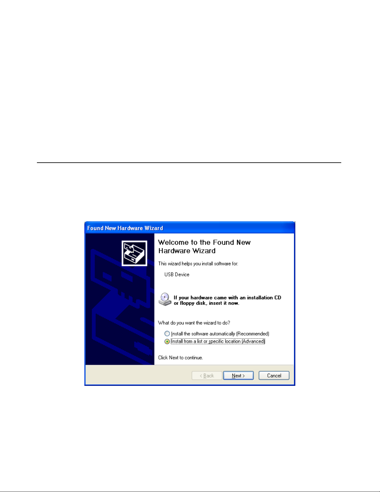
3. The computer will automatically detect the meter with a message “New Device Found”. It will then prompt for the
installation driver (figure 1). Select “Install from a list or specific location (Advanced)” and click “Next”:
Figure 1: The computer automatically prompts for installation driver
1
Page 2
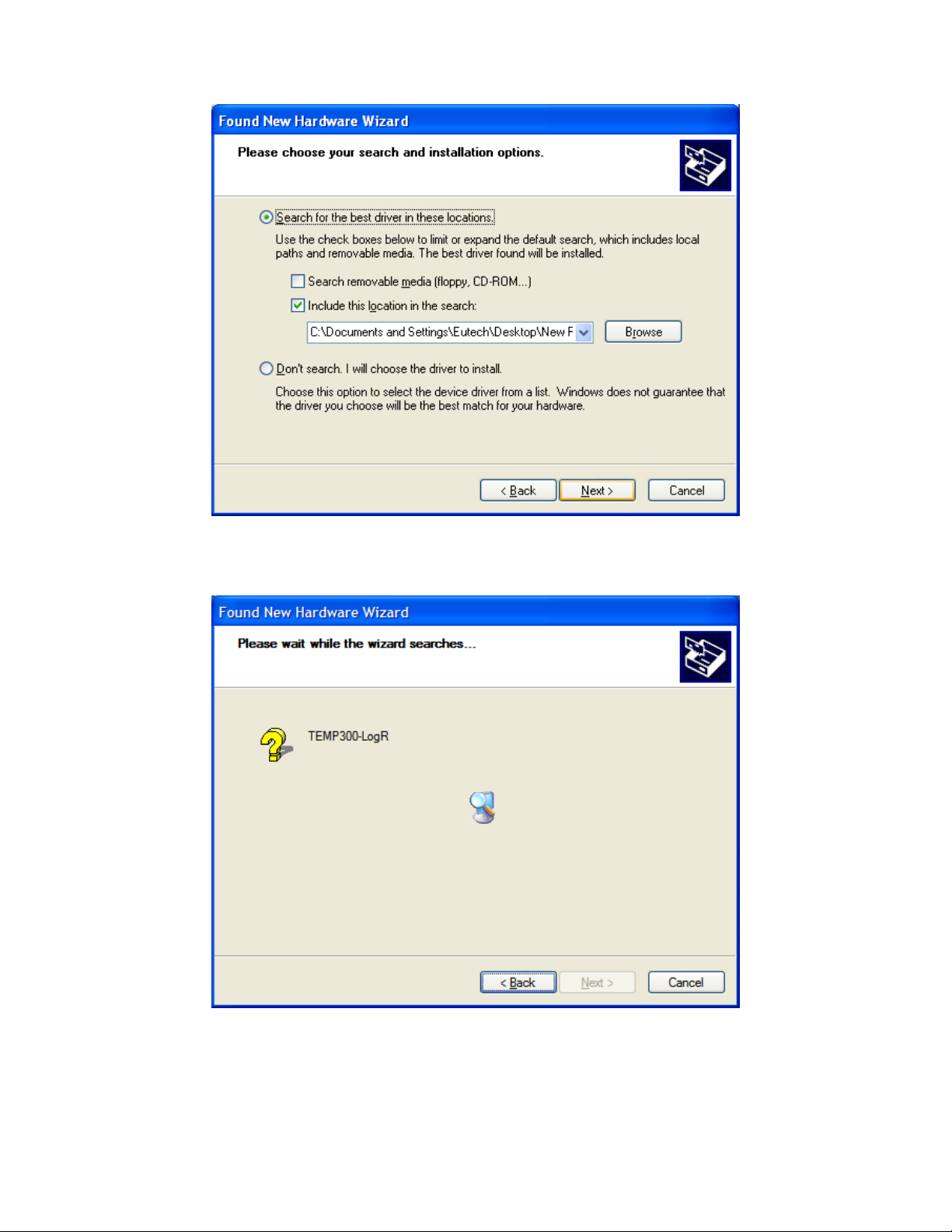
4. Select “Search for the best driver in these locations”. Check “Include this location in the search:”, then click
“Browse” to search for the driver within the CD Drive (figure 2). Click “Next” to continue.
Figure 2: Direct the installation wizard to the CD
5. The computer starts installing the driver (figure 3).
Figure 3: Driver installation in progress
2
Page 3
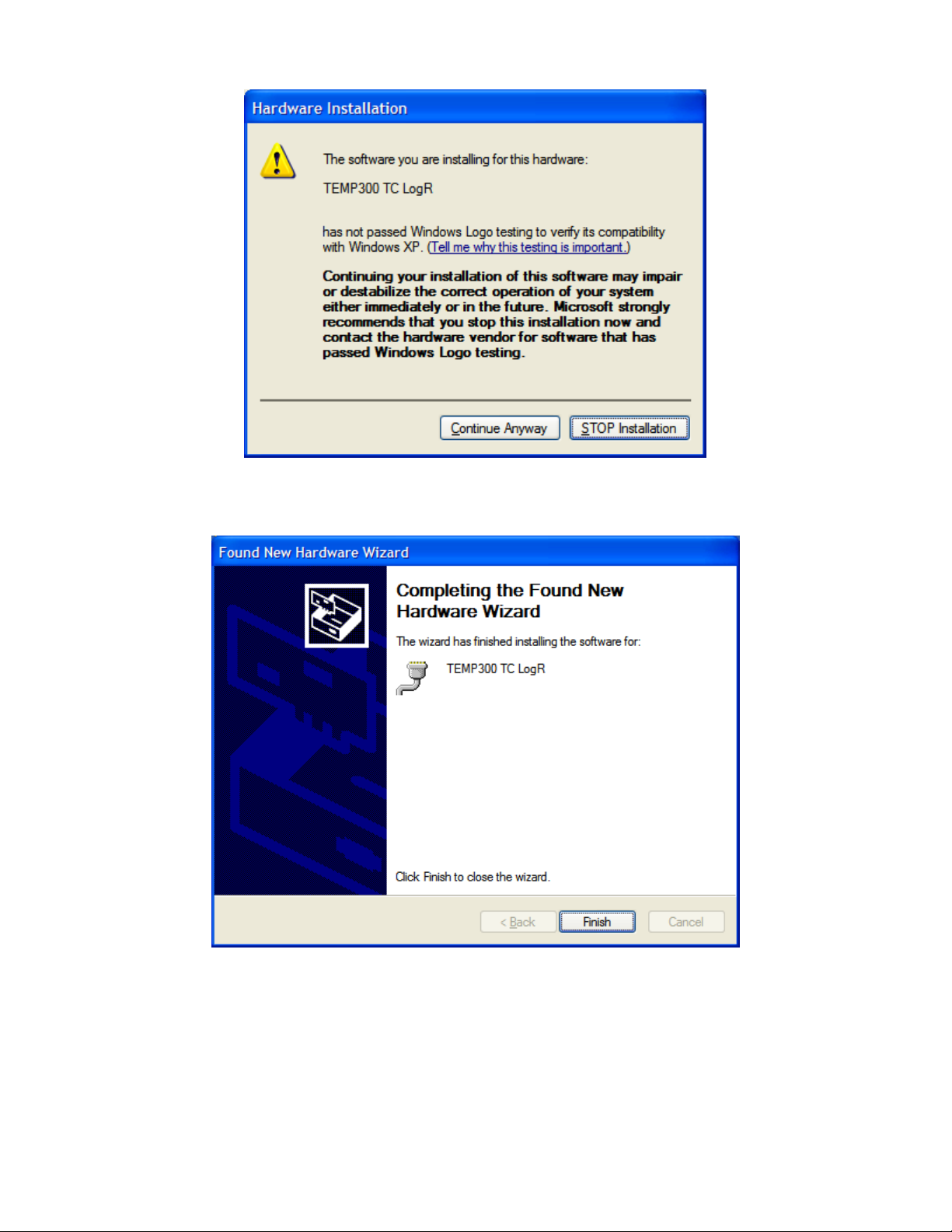
6. A prompt appears at the end of the installation (figure 4). Click “Continue Anyway”.
Figure 4: Select “Continue Anyway”
7. Select “Finish” to close the wizard (figure 5):
Figure 5: Select “Finish” to complete installation
3
Page 4
Installing the USB Communication Driver for Temp 340/ 360 (Refer to page 1 if you are using Temp 300)
1. Insert the USB Communication Driver into the CDROM of your computer.
2. Connect your Temp 340 or 360 to your computer using the provided USB cable.
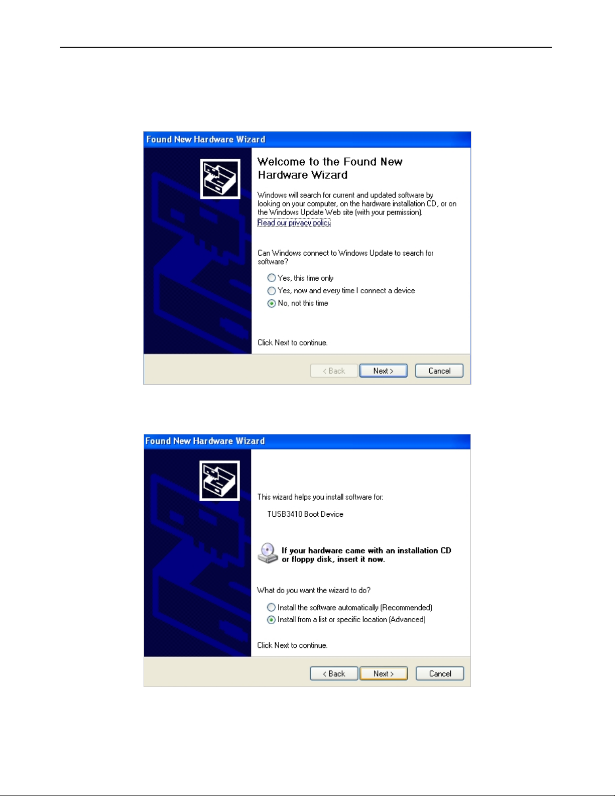
3. The computer will automatically detect the meter with a message “Found New Hardware: TUSB3410 Boot Device”.
It will then launch the New Hardware Wizard (figure 6). Select “No, not this time”, and click “Next”.
Figure 6: The computer automatically launches the New Hardware Wizard
4. The New Hardware Wizard will prompt you for the driver CD. Select “Install from a list or specific location
(Advanced)” and click “Next” (figure 7).
Figure 7: The computer automatically prompts for installation driver
4
Page 5

5. Select “Don’t search. I will choose the driver to install”. Click “Next” to continue.
Figure 8: Select Manual Search
6. Select “Multi-port serial adapter” as the Hardware Type (figure 9) and click “Next”.
Figure 9: Select Multi-port serial adapters
5
Page 6

7. The Wizard then prompts you to select your device driver. Click on “Have Disk…”, then “Browse” to select your
driver.
Figure 10: Click “Have Disk” followed by “Browse” to select driver
8. Select your CD drive and select folder “Temp 340_360”, then file “usbuart3410.inf” (figure 11).
Figure 11: Locate the file usbuart3410.inf within the driver CD
6
Page 7

9. The New Hardware Wizard should now show the “TEMP360 RTD LogR” in the Wizard window (ensure that the
“Show compatible hardware” box has been checked). Click “Next” to continue.
Figure 12: Locate the file usbuart3410.inf within the driver CD
10. The wizard will start installing the software. A prompt appears at the beginning of the installation (figure 13). Clic k
“Continue Anyway”.
Figure 13: Select “Continue Anyway”
7
Page 8

11. Select “Finish” to close the wizard (figure 14):
Figure 14: Select “Finish” to complete installation
8
Page 9

Data Transfer From Meter To PC
1. Connect your Temp 300, 340 or 360 to your computer
2. On your computer, go to “Start” Æ “All Program” Æ “Accessories” Æ “Communications” Æ “HyperTerminal”. The
program will prompt you for Location Information (figure 15). Click “Cancel”.
Figure 15: Click cancel when the HyperTerminal program prompts for Location Information
3. Provide any name under the “Name” field, then click “OK” (figure 16).
Figure 16: Provide any name in the HyperTerminal window
9
Page 10

4. Select the COM port (usually COM6, COM7 or higher) which your thermometer is usi ng (figure 8). To find out the exact
COM port, go to “Start” Æ “Control Panel” Æ “System” Æ “Hardware” Æ “Device Manager” Æ “Ports”. Expand to see
the ports details. Plug out and in your Thermometer handheld to see which COM it is using (Figure 17).
Figure 17: Select the COM port which your thermometer is using
Figure 18: Plug your thermometer handheld in and out to see which COM port it is using
10
Page 11

5. You will be prompted to ent er the COM port details after you have selected the COM port which your thermometer
handheld is using. Set your port settings as below (figure 19):
For Temp 300: For Temp 340 / 360:
• Bits per second: 19200
• Data bits: 8
• Parity: None
• Stop bits: 1
• Flow control: Hardware
• Bits per second: 57600
• Data bits: 8
• Parity: None
• Stop bits: 1
• Flow control: Hardware
Figure 19: Set your port settings as shown here
6. On the meter set-up page, go to “Menu - Data Logging”. Ensure that the Location field is set to “PC”.
Figure 20: Datalogging menu
7. To start datalogging, return to the measurement menu and press the “LOG” button.
8. To transfer data from your thermometer handheld to your computer, access the Data Transfer Page (under Data
Logging Page) and select “Start” to start transmitting the data.
11
 Loading...