

Page 1
99 Washington Street
Melrose, MA 02176
Phone 781-665-1400
Toll Free 1-800-517-8431
User Manual
Visit us at www.TestEquipmentDepot.com
Temperature and Temperature/RH
Data Loggers with USB Interface
Models 20250-41, -42, -43, -44
THE STANDARD IN PRECISION MEASUREMENT
Page 2

Introduction
The Digi-Sense USB Data Logger measures ambient temperature and records up to
32,000 readings). Models 20250-42 and 20250-43 also measure relative humidity. Program
sampling rate, high/low alarm levels, and start mode using the provided software. Download
logged data via the integrated USB interface for analysis, graphing, and documentation.
Careful use of this instrument will provide years of reliable service.
Unpacking
Check individual parts against the list of items below. If anything is missing or
damaged, please contact Cole-Parmer immediately.
1. Data logger
2. Clear USB connector cover
3. Type K thermocouple (model 20250-44)
4. Mounting clip with screws
5. Software CD
6. One 3.6 V battery
7. User manual
Key Features
• Status indication via green and yellow/red LEDs
•
Integrated USB interface for setup and data download
User-settable high/low alarms
•
•
Real-time mode—lets you monitor and log measured data in real time
while the logger is still plugged into the computer’s USB interface
Logger Description
1. Clear USB connector cover
2. USB interface to PC port
3. Manual START button
4. Access to battery
5. Internal sensor
(models 20250-41, -42, -43)
6. Input for external type K
thermocouple sensor
(model 20250-44)
7. Record LED (green)
8. Alarm LED (yellow/red)
9. LCD (model 20250-43)
10. Mounting clip
2
1
2
3
4
5
6
78
9
10
Page 3
Setup and Operation
1. Insert the software CD into the PC. Double click the set up.exe file to launch the software
installation program.
2. Follow the installation wizard to complete installation; when complete, the “Datalogger”
software icon shortcut will be automatically placed on the PC desktop.
3. Plug the data logger into the computer USB port and double click on the “Datalogger”
software icon to launch the software.
4. Left click on the “Datalogger Setup” icon (tool image) in the top left corner to open
the “Setting” tab.
Manual start mode: Allows you to move logger to a remote location. T
o start recording,
press and hold the Start button for 3 seconds until the green LED lights up. To stop
recording, press and hold the Start button for 6 seconds until the red LED lights up.
Instant start mode: Recording begins automatically once the logger is removed from
the computer USB port.
5.
Refer to the "Software Setup and Operation" section on pages 4–7 for full instructions.
Note: Model 20250-44 must have the external type K thermocouple sensor connected
before recording.
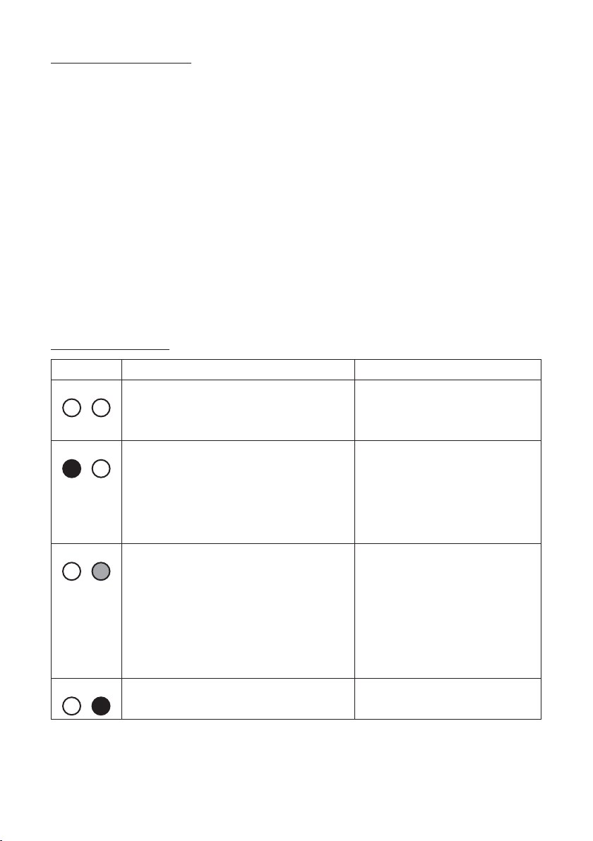
LED Status Guide
LEDs Indication Action needed
REC ALM
REC ALM
Both LED lights off
– Logging not active —
– No battery inserted or dead battery
‡
Green single flash every 10 seconds*
– Logging in progress, no alarm condition —
Replace battery and download data
Green double flash every 10 seconds*
– Delayed start To start, hold the Start button until
green and yellow LEDs flash
REC ALM
Yellow single flash every 10 seconds*
– Logging in process, LOW alarm condition
†
—
Yellow double flash every 10 seconds*
– Logging in process, HIGH alarm condition
†
—
Yellow single flash every 60 seconds
– Memory is full Download data
REC ALM
*To conserve battery life, increase the LED flashing cycle to 30 seconds using the provided software.
†
The LED status indication alternates every cycle. For example: If there is one alarm, the REC LED blinks
for one cycle and ALM LED will blink for next cycle.
‡
When the battery is low, all operations will be disabled automatically (logged data will be retained).
Replace the battery and use provided software to restart logging operation and to download logged data.
Red single flash every 60 seconds
– Low battery
‡
Replace battery and download data
3
Page 4

Software Setup and Operation
Installation
1. Insert the supplied data logging software
CD into the PC.
2. Double click the set up.exe file to launch
the software installation program
3. Follow the installation wizard to complete
the installation.
4. Upon successful installation, the “Datalogger” software icon shortcut will be automatically placed on your PC desktop.
5. To initiate the software, double click on
the “Datalogger” software icon. An easy to
follow user interface will display. A user
guide can be produced by selecting the
“Help” option followed by “contents” from
the user interface.
➞
6. Ensure the data logger is connected
successfully before programming.
➞
Open Function
Click on it to open previously logged data
file for viewing or further analysis. When
selected, the open screen will list data files
saved earlier. Clicking on a file of interest
will automatically load and display the data
graph.
Save Function
Save logged data to a file for keeping or
future analysis. When selected, the software
will allow you to save the data in a default
location or one of your choosing for access
later through the open selection. The data
can be saved in the default “.ITMR” format
or “.CVS format”.
Real-time Function
Click on the clock icon to initiate data
recording while the logger is still plugged
into the computer USB port. This is particularly useful when familiarizing yourself
with the data logger by allowing you to
immediately view the impact of changing
the various settings.
Download Function
Click on the arrow icon to download data
currently saved in the data logger plugged
into the computer USB port. When selected,
the downloaded data will replace any data
currently displayed.
Datalogger Setup Function
Click on the tool icon to set the start and
logging mode and parameters of the data
logger plugged into the computer USB port.
Functions
Open Save Real
4
time
Down-
load
Data-
logger
setup
Help
This settings menu allows you to select the
start mode, the sample rate and maximum
sample points, the LED flash rate, alarm levels, and temperature units. Once the settings are selected, they are accepted by
clicking on the setup button on the screen.
This will also clear any stored data on the
data logger so data of value should be
saved before initiating a new setup.
Help Function
Click on it to download the user manual or
find answers to data logger questions.
Page 5

Operating Mode Settings
Data logger has two operational settings
from which to choose: “Datalogger”
operation or “Real-time” operation.
“Datalogger” Operating Mode:
Allows you to set up the logger for remote
temperature and humidity logging with the
user selectable settings as shown below:
➞
Manual Start Mode: lets you remove the
logger from the computer USB port once
the settings are programmed and move it to
the location of interest without it starting.
Operation is initiated manually by pressing
the Start button on the housing for 3 seconds until the green LED lights up.
Instant Start Mode: allows the logger to
begin recording automatically once it is
removed from the computer USB port.
Sample Rate: set rate from 2 seconds to
24 hours between data samples.
Max Points: select the number of samples
up to 32,000 (16,000 per channel).
Record Time: calculates the run time based
on sample rate and max points selected.
LED flash cycle: increase the flash cycle to
conserve battery life. (See "LED Status
Guide" on page 3.)
Enable high and low alarm: click to access
the Temperature and Humidity (RH models
only) settings. Program both the high and
low alarm limits. (See "LED Status Guide"
on page 3 to identify alarm conditions.)
➞
Temperature Unit: choose either Fahrenheit
or Celcius to log and display temeperatures.
Humidity Unit (RH models only): preset as
%RH.
5
Page 6

Software Setup and Operation (continued)
“Real-time” Operating Mode:
Allows you to monitor and log the measured data in real time while the logger is
still plugged into the computer USB port.
In the “Real-time” mode, the logger only
has an immediate start mode which is initiated by clicking on the clock icon in the
upper left of the display screen.
➞
Set the Sample rate(s), the Max number of
data samples, and the Temperature Unit
to your desired settings. The Humidity
Unit (RH models only) is preset as %RH.
Click the Setup button to approve the
settings.
➞
After a few seconds, the real-time temperature and RH readings measured by the
logger will show in the upper left quadrant
of the display and the logged data will show
in the lower left sector of the screen. The
graphic display will show the measured
temperature trend.
Data in the real-time mode will continue
to collect and display until the number of
samples selected is logged.
➞
6
Page 7

Graphing Options
Clicking on words “Graph with markers”
toggles between adding or removing
markers at each data point.
Graph with markers
➞
Graph without markers
➞
Zoom – Pan Options
Easy yet powerful zoom and pan options
are available for providing a more detailed
view of graphic data. The zoom option is
automatically accessed by using the mouse
roller adjustment to zoom in or out depending on roll direction. To pan through the
graph, just click the left mouse button when
pointing at the area of interest and hold it
down while moving the mouse to a central
location on the graph.
To return to the original view, right mouse
click anywhere in the graph and click on
“Set scale to default” from the pull-down
menu. Other options available on the pulldown menu allow you to copy or save the
graphic image, print a hard copy of the
graph, and show the point values on the
graph under the cursor.
7
Page 8

Maintenance and Repair
Sensor Reconditioning (Models 20250-41, -42, -43)
Over time, the internal sensor may be compromised as a result of pollutants, chemical
vapors, and other environmental conditions which can lead to inaccurate readings. To
recondition the internal sensor:
•
Bake the data logger at 176°F (80°C) at <5% RH for 36 hours, followed by
70 to 90°F (20 to 30°C) at >74% RH for 48 hours (for rehydration).
If permanent damage to the internal sensor is suspected, replace the data logger
immediately.
Battery Replacement
With a pointed object (e.g. small screwdriver), open the casing. Gently pull off the casing
and replace the 3.6 V lithium battery
green, yellow, green). Slide the logger back into the casing until it snaps into place.
. The two LED indicators will briefly light up (alternating
1 2 3 4
➞
➞
Note: Leaving the data logger plugged into the USB port for longer than necessary
will cause some of the battery capacity to be lost.
For Product and Ordering Information, Contact:
99 Washington Street
Melrose, MA 02176
Phone 781-665-1400
Toll Free 1-800-517-8431
Visit us at www.TestEquipmentDepot.com
1065DGMAN_20250-41,-42,-43,-44 Rev.1
Manual Part No. 00100-72
 Loading...