

Page 1
OPERATING MANUAL
12-Channel Scanning
Thermocouple Thermometer
MENU
EXIT
+ALARM
9
SCAN0CLEAR
1
STORE2 LOG
3
RECALL
4
PRINT
5
MAX
6
MIN
7
AVG
°F
8
HOLD
Model No.
92000-00 Benchtop 115V
92000-05 Benchtop 230V
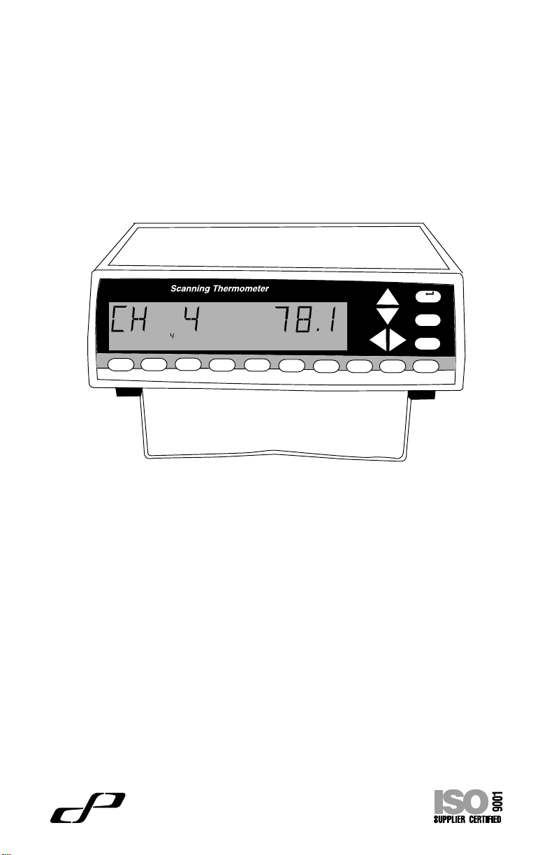
Each of the up to 12 thermocouples is scanned once every four seconds to once ever y
hour (settable). The current readings are displa yed on the large liquid crystal display . Readings that exceed a maximum or minimum value can be set to tr igger an alarm.
Thermocouples of types: B, E, J, K, N, R, S or T can be used.
Up to 4,680 data points can be logged (stored) within the unit, including readings from all
12 channels and the date and time of the readings.
The unit can be directly connected to a printer to provide a continuous printout, and/or to
your computer. Software to permit a personal computer using WINDOWS
from the unit, remotely operate the unit, and synchronize the operation of multiple units
is included.
Cole-Parmer Instrument Co.
625 East Bunker Court
(847) 549-7600
(847) 247-2929 (fax)
800-323-4340
www.coleparmer.com
e-mail: techinfo@coleparmer.com
A-1299-0763
Edition 04
Cole
Vernon Hills, Illinois U.S.A. 60061-1844
®
Parmer
®
to store data
Page 2
EU Declaration of Conformity
Name of Apparatus: Scanning Thermocouple Thermometer
Model Number: 92000-05
Description of Apparatus: 12-Channel Benchtop Thermocouple
Scanner
Barnant Company declares that the above model is in conformity
to the following harmonized standards and directives:
Applicable Applicable Manufacturer’s
Directives Specifications Report Number
73/23/EEC EN61010-1/A2: 1995 TR9866
93/68/EEC
89/336/EEC EN61326-1/A1: 1998 TR9867
92/31/EEC
93/68/EEC
The last two digits of the year in which the current configuration of
the the above model was assessed per the Low Voltage Directive
is: 00.
Manufacturer:
Barnant Company Division
Cole-Parmer Instrument Company
28W092 Commercial Avenue
Barrington, IL 60010-2392
USA
Tel.: 847-381-7050
Manufacturer’s Signature:
James W . Doll Date
Vice President, Engineering
10 November, 2000
Printed in U.S.A.
040101
Page 3
Introduction
Safety Precautions
Introduction
This Scanning Thermocouple Thermometer continuously monitors
temperatures at up to 12 locations. It is designed for laboratory or
industrial applications for unattended temperature monitoring. An alarm is
set off when any thermometer exceeds its preset minimum or maximum
temperature. Temperature data is stored within the unit and can be
output to a printer or PC.
Safety Precautions
DANGER: If thermocouples are at a high voltage, this voltage may be
present at other points inside the instrument and outside at
all the connectors.
WARNING: Disconnect or turn off power source before making
connections.
WARNING: Turn power off and completely disconnect instrument.
Disconnect power source, thermocouples, computer, links,
and printer.
WARNING: Other than a lithium battery, there are no user serviceable
parts inside. Replacement of the lithium battery must be
performed per the Maintenance section of this Operating
Manual. Refer servicing to your dealer.
CAUTION: Be sure available power matches instrument power require-
ments.
CAUTION: Protection provided by the unit may be impaired if the unit is
installed and/or operated in a manner inconsistent with
these instructions.
WINDOWS, WINDO WS NT - Reg TM Microsoft Corp.
CENTRONICS - Reg TM Genicom Corporation
Trademarks bearing the ® symbol in this publication are
registered in the U.S.A. and in other countries.
1
Page 4

Table of Contents
Page
Introduction ................................................................................. 1
Safety Precautions ...................................................................... 1
Table of Contents ........................................................................ 2
Features ...................................................................................... 4
Package contents........................................................................ 5
Quick reference:
Front panel controls.............................................................. 6
Front panel display ............................................................... 8
Rear panel connections........................................................ 8
Rear panel connections
Thermocouple connections .................................................. 9
Power switch ........................................................................ 9
10-28V DC jack .................................................................... 10
PC/IN jack............................................................................. 10
OUT/LINK jack...................................................................... 11
PARALLEL PRINTER connection......................................... 11
TRIGGER + GND connection............................................... 11
Installation ................................................................................... 12
Front panel displays and controls
1 STORE button ................................................................... 13
2 LOG button ........................................................................ 14
3 RECALL button.................................................................. 15
4 PRINT button ..................................................................... 16
5 MAX button........................................................................ 17
6 MIN button ......................................................................... 18
7 AVG button......................................................................... 19
8 HOLD button...................................................................... 19
9 SCAN button...................................................................... 20
0 CLEAR button.................................................................... 20
MENU button ........................................................................ 21
Up-Down Arrow keys ............................................................ 21
Left-Right Arrow keys ........................................................... 22
EXIT button........................................................................... 23
ALARM button ...................................................................... 23
Temperature alarms .......................................................... 23
Other alarms ..................................................................... 25
MENU
About the MENU................................................................... 26
2
Page 5

Table of Contents continued
Page
MENU - How to:
Set the Scale ........................................................................ 28
Change the resolution .......................................................... 29
Enable/Disable channels ...................................................... 30
Setup thermocouple types.................................................... 31
Adjust the display contrast.................................................... 32
Set trigger type ..................................................................... 33
Set trigger mode ................................................................... 34
Adjust the scan rate.............................................................. 35
Adjust the print rate .............................................................. 36
Adjust the log rate................................................................. 37
Set the alarm mode .............................................................. 39
Set the alarm print ................................................................ 40
Set HI alarm(s) ..................................................................... 41
Set LO alarm(s) .................................................................... 42
Set alarm hysteresis ............................................................. 43
Adjust HI alarm setpoints...................................................... 44
Adjust LO alarm setpoints .................................................... 45
Enable/Disable the alarm beeper ......................................... 46
Set the date format ............................................................... 47
Set the date .......................................................................... 48
Set the time .......................................................................... 49
Do a field calibration ............................................................. 50
Print a calibration report ....................................................... 53
Calibration to water............................................................... 55
Power up modes ......................................................................... 56
Maintenance
Care and cleaning ................................................................ 57
Battery .................................................................................. 58
Warranty...................................................................................... 59
Product Return ............................................................................ 59
Technical Assistance................................................................... 59
Specifications .............................................................................. 60
Appendices
A Error messages .................................................................... 62
B Guidelines to Thermocouple Selection................................. 63
C Temperature conversion ....................................................... 63
D Menu flow chart .................................................................... 64
E Factory default settings......................................................... 66
3
Page 6

Features
Input
• Up to 12 thermocouple probes, each connected to a separate channel.
• Thermocouples can be different types.
• Thermocouples of types B, E, J, K, N, R, S or T can be used.
• Channels can be individually enabled or disabled.
Data storage
• Up to 4,680 data records can be stored in the unit (a record includes
readings of all 12 channels plus time and date).
• Data can be logged (automatically stored).
• Current data can be manually stored by pushing the STORE button.
• Data is maintained even when the instrument is turned off or un-
plugged from power.
Display
• Displays the thermocouple number and temperature as scanned.
• Operator can set the scan interval from a minimum of 4 seconds to a
maximum of 1 hour.
• Readings can be stored and displayed in °C, °F, K, or °R.
• Resolution to 0.1° can be displayed.
• Display can sho w: current, maximum, minimum, or average temperature .
• Average temperature display also displays the number of readings
being averaged.
• Hold function freezes all 12 channels.
Data output
• All 12 channels can be output to a printer simultaneously.
• Current, stored, or logged data can be directly sent to a printer
(CENTRONICS® parallel).
• Time between printing cycles is adjustable.
• Current, stored, or logged data can be sent to a personal computer
(PC)(RS-232 serial).
Calibration
• Channels can be individually calibrated manually.
• F actory calibration remains in memory and can be restored at any time.
Software
• Software (for a PC running WINDOWS 95/98 or WINDOWS NT) is
included.
• Software use is optional.
• Software installation instructions and software manual are on the
provided CD-ROM. See readme.txt for latest information.
• Software permits control of up to 8 units.
• Real time data collection.
• Data can be input to spreadsheet or graphing software.
4
Page 7
Features continued
Package contents
Alarms
• High and low alarm temperatures can be set for each channel
individually.
• An open thermocouple automatically triggers an alarm.
• An alarm causes the alarm icon to be displayed, and emits an audible
beep.
• The audible beep can be disabled.
Error messages
• Messages indicate channel and fault condition.
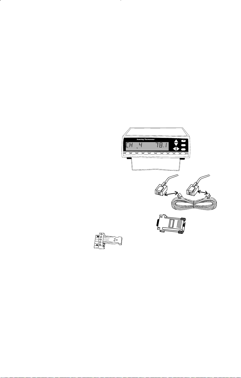
Package contents
MENU
°F
Scanning thermometer
Includes wire stand for desktop
1
STORE2 LOG
convenience.
Link cable
RJ-11 to RJ-11 seven feet long. Use to
interconnect scanning thermometer instruments.
3
5
6
4
RECALL
PRINT
7
MAX
MIN
AVG
EXIT
+ALARM
9
8
SCAN0CLEAR
HOLD
PC adapter
RJ-11 to DE-9 female. Used to connect
instrument to your PC, using the link cable.
Trigger Connector
Operating Manual
This book.
Warranty card
AC Adapter - as supplied.
Software
WINDOWS 95/98 and WINDOWS NT on CD-ROM. Serial software specifications on CD-ROM.
Not supplied
Printer cable
DB25 male to the input connection of your parallel printer.
5
Page 8
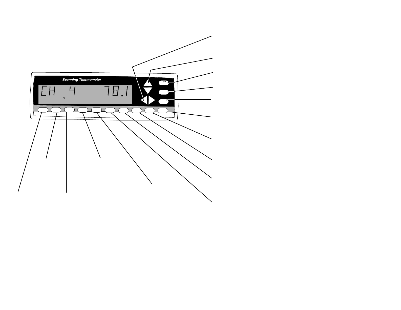
Quick Reference
Front Panel Controls
See the page number (in parenthesis) for full information about the item.
Use Left-Right arrow keys to select a channel for display. Scanning
stops. Push SCAN to resume. (22)
Use Up-Down arrow keys to scroll thru the MENU. Otherwise inactive. (21)
MENU Push to sequence through menu choices for instrument setup. (21)
1
STORE2 LOG 3RECALL
LOG Push to
toggle data
logging. (14)
STORE Push to
store the current set
of readings in
memory. “STORE”
appears in the
display. (13)
4
PRINT
5
MAX
6
MIN
PRINT Push to
turn printing on
or off. (16)
RECALL Push to scroll
through logged readings.
Up-Down arrow keys scroll
through reading numbers.
Left-Right arrow keys
select channel displayed.
RECALL cycles through
reading date, reading time,
and reading temperature.
Push and release EXIT to
exit. (15)
°F
7
AVG
8
HOLD9SCAN
0
CLEAR
MAX Push to display the
maximum reading and time
since last power up or last
cleared. Left-Right arrow
keys select channel displayed. To reset push
CLEAR then MAX. To exit
push EXIT. (17)
MENU
EXIT
+ALARM
EXIT Push to exit any menu or display mode. Operation continues. (23)
ALARM Push to silence the audible alarm. Alarm icon remains. (23)
CLEAR Push CLEAR then push STORE, LOG, MAX, MIN, AVG or ALARM.
Clears respective value(s) from memory. (20)
SCAN Push to resume scanning display after pushing Left-Right arrow
keys. Also, this immediately initiates a new scan. (20)
HOLD Push to freeze current display readings. Scanning continues.
Left-Right arrow keys select channel displayed. To exit push HOLD. (19)
AVG Push to display the average reading and number of readings since
last power up or last cleared. Left-Right arrow keys select channel displayed. To reset push CLEAR then AVG. To exit push EXIT. (19)
MIN Push to display the minimum reading and reading time since last
power up or last cleared. Left-Right arrow keys select channel displayed. To
reset push CLEAR then MIN. To exit push EXIT. (18)
6 7
Page 9
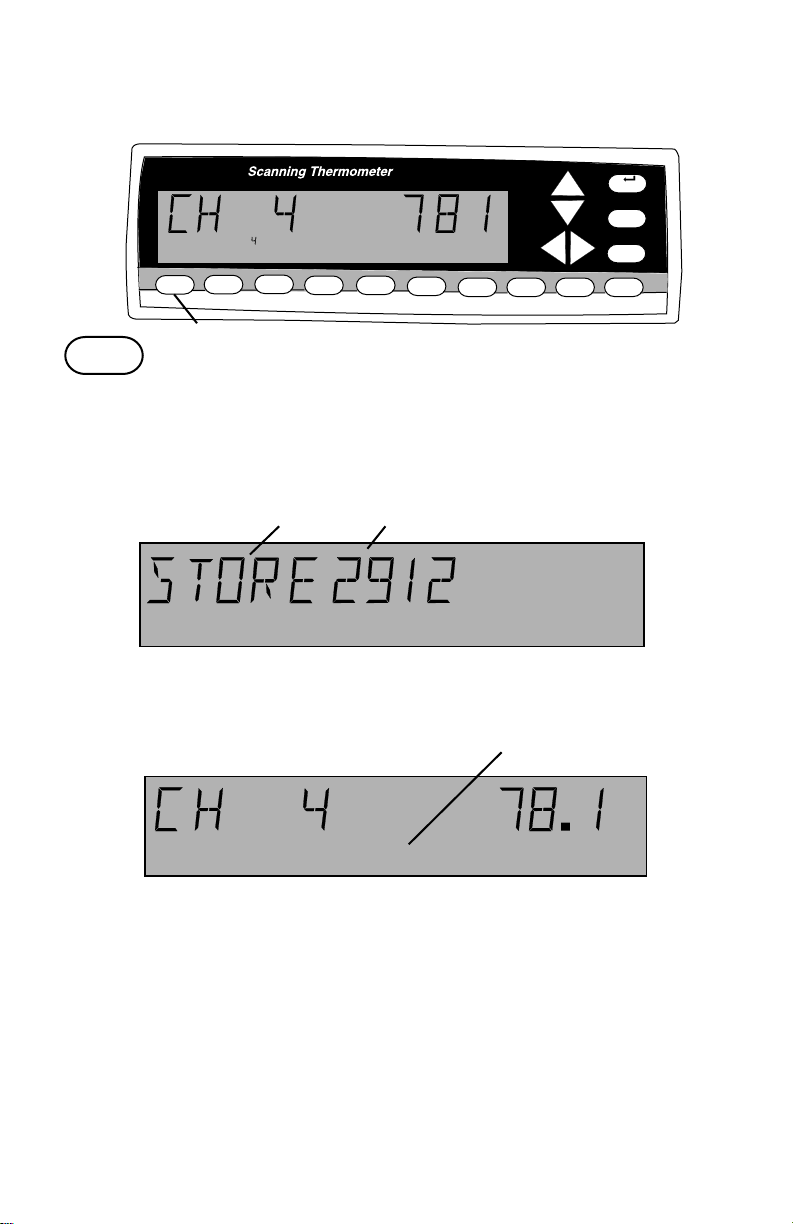
Quick Reference Continued
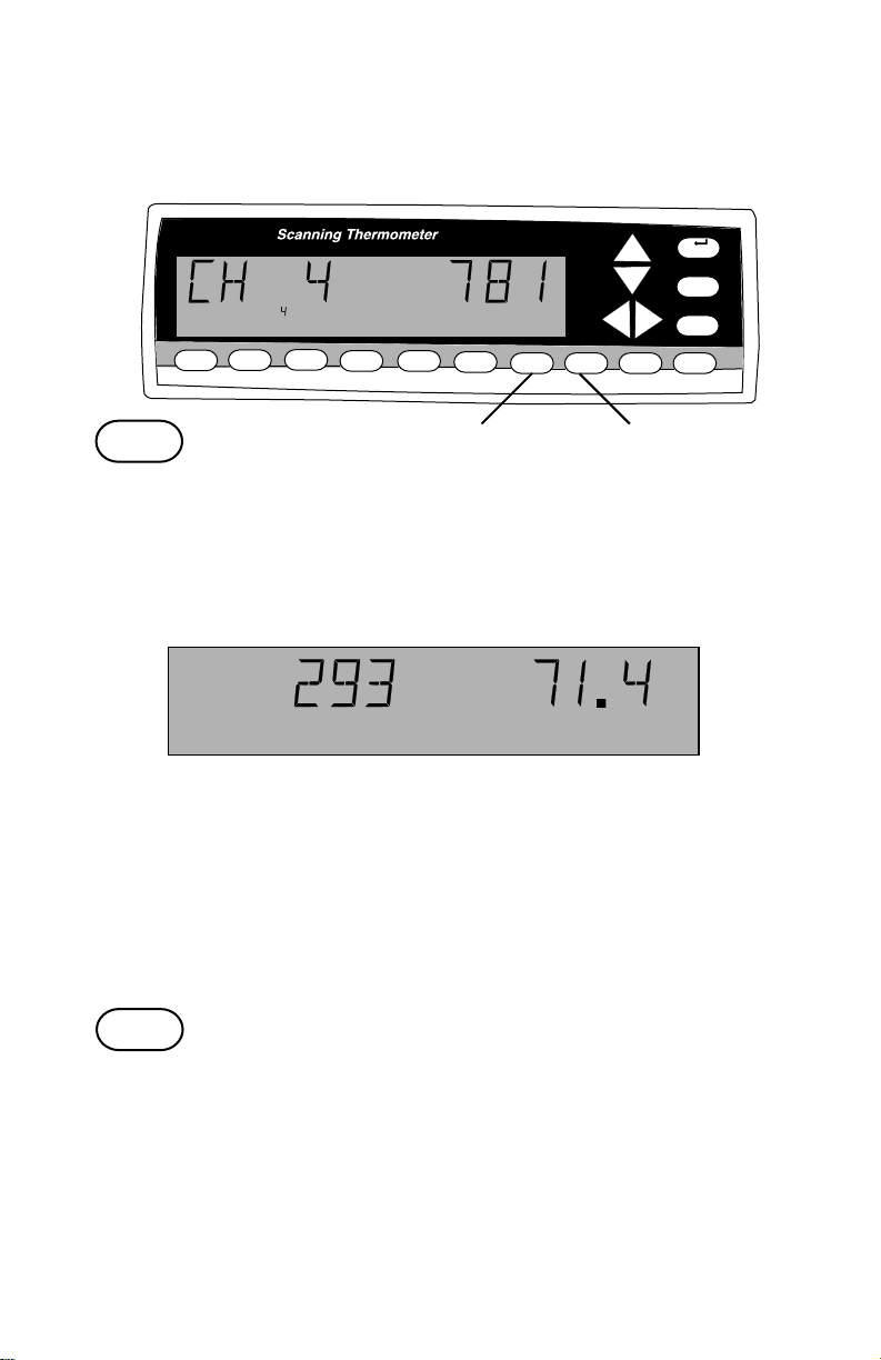
Front Panel Display
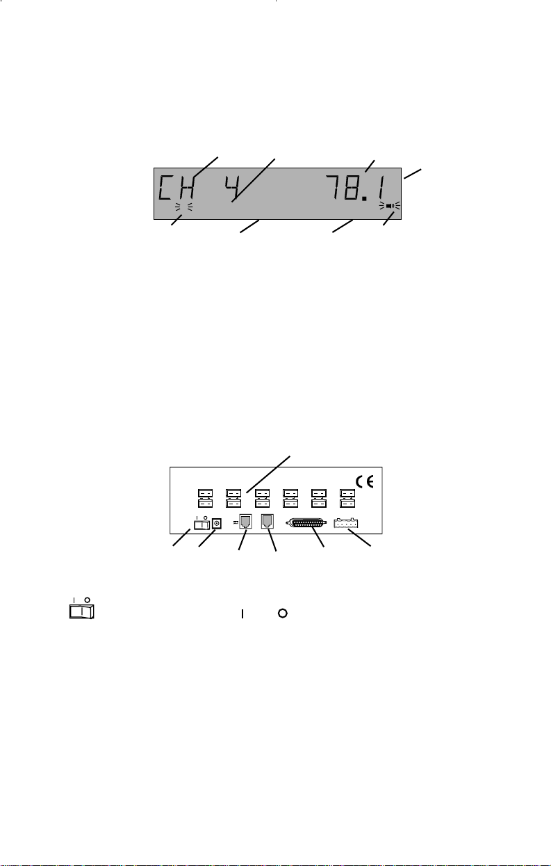
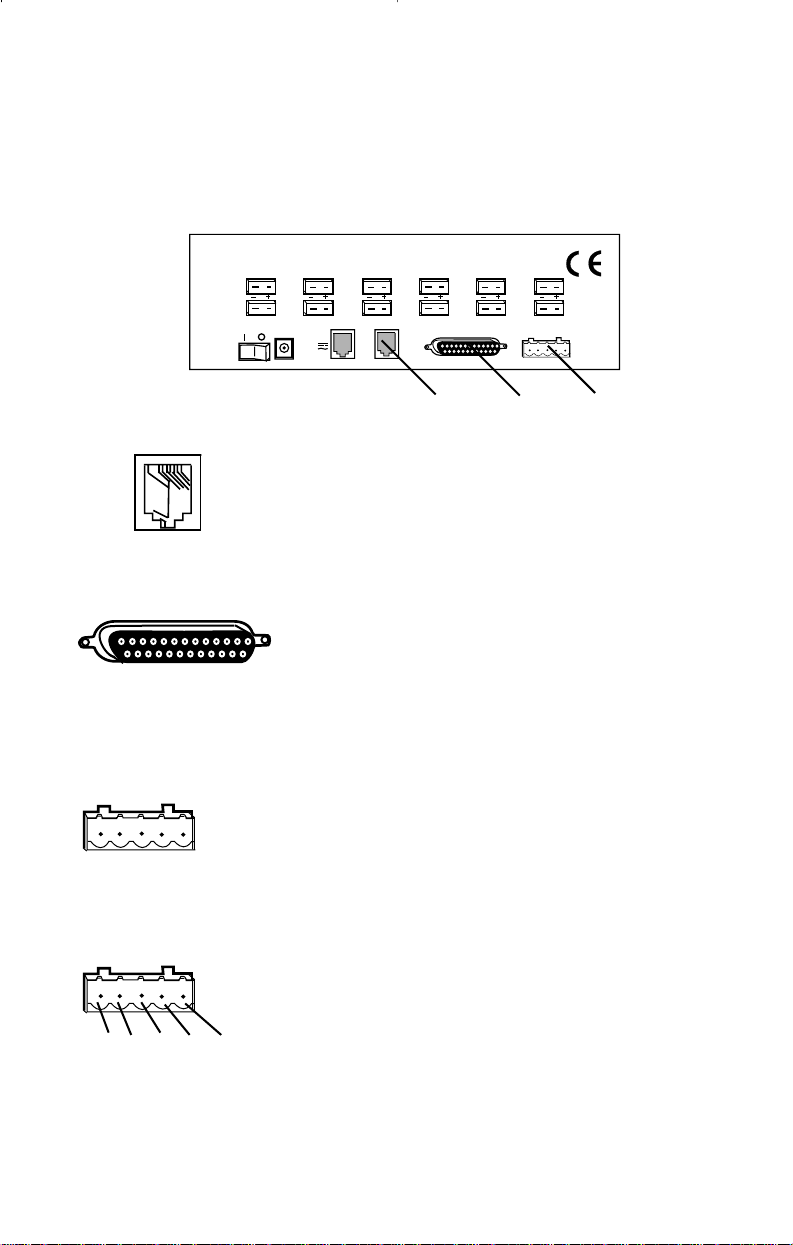
Rear Panel Connections
1 2 3
2
4
STORE
56 78
Note: Example display
1. CH and the channel number
display the thermocouple that is
being read.
2. The number of the channel being
displayed is repeated here.
3. The temperature is displayed.
4. The temperature scale is given.
5. A flashing channel number
shows a problem with that probe.
12 CHANNEL TERMOCOUPLE SCANNER
1728394105116
PC/IN
RS-
10-28 VDC
232
7-20 VAC
500 MA
°F
ALARM
6. Words across the bottom of the
display indicate status of the
instrument. (Example: STORE
indicates that temperature
records are logged or stored.)
7. The word ALARM flashes when
an alarm is present.
8. When flashing, indicates an
alarm.
1.
MODEL ####-##
Mfg. By Barnant Company
Barrington, IL 60010-2392
USA
PARALLEL PRINTER
12
TRIGGER
+ GND
OUT/LINK
4
2. 3. 4. 5. 6. 7.
1. 1-12 Connect thermocouples here (two blade mini-ANSI
connectors).
2. Power switch: = on, = off.
3. 10-28V DC Power supply input. Connect the input connector of the
supplied AC adapter here.
4. PC/IN Connect (using supplied cable) to a serial port on your PC
computer (RS-232 connection).
5. OUT/LINK For linking additional 12-Channel Scanning Thermocouple
Thermometer instruments. Connect OUT/LINK on one
instrument to PC/IN, using RJ-11 connectors.
6. PARALLEL Use a standard parallel printer cable (25 pin D-sub
PRINTER connector) to directly connect a PC printer.
7. TRIGGER + Connect for external events to trigger printing or
GND data storage.
8
Page 10
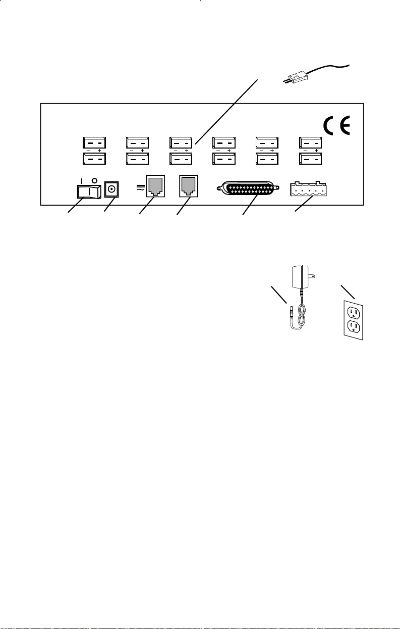
A
12 CHANNEL TERMOCOUPLE SCANNER
1
7
2
8
10-28 VDC
7-20 VAC
500 MA
PC/IN
B
Rear Panel Connections
Thermocouple connections
Power switch
MODEL ####-##
Mfg. By Barnant Company
Barrington, IL 60010-2392
USA
3
9
4
10
OUT/LINK
RS232
5
11
PARALLEL PRINTER
12
6
TRIGGER
+ GND
1
7
2
8
3
9
10
4
5
11
6
12
A. Thermocouple connections
• Connect up to twelve thermocouples here.
• Jacks are for two blade mini-ANSI connectors.
• Thermocouples of types B, E, J, K, N, R, S, or T can be used. See
Appendix B for a description of thermocouple types.
• Any combination of thermocouple types can be used at the same time.
• If a thermocouple connection (channel) is not used it may be disabled
using the Menu. See Menu - How to: Enable/Disable channels on
page 30.
B. Power switch
Toggle to l to turn power to the instrument on.
Toggle to 0 to turn power to the instrument off.
When power is turned on the display goes through a display check
sequence: all display elements are turned on momentarily, then
the 1,2,...12 icons (small numbers) turn off in sequence, and then the
display switches to normal operation.
An internal lithium battery maintains the real-time clock for power outages for over a year.
9
Page 11
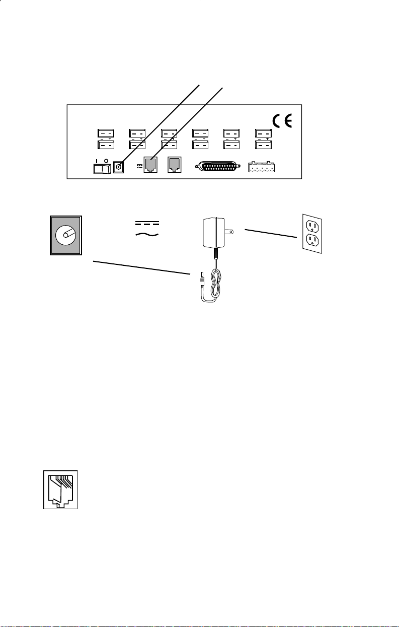
Rear Panel Connections continued
10-28V DC jack
PC/IN jack
1
7
12 CHANNEL TERMOCOUPLE SCANNER
2
8
10-28 VDC
7-20 VAC
500 MA
3
9
PC/IN
RS232
A
4
10
OUT/LINK
10-28 VDC
7-20 VAC
500 MA
A. 10-28V DC jack (Power supply input)
Connect the input connector of the supplied AC adapter here.
5
11
PARALLEL PRINTER
B
MODEL ####-##
Mfg. By Barnant Company
Barrington, IL 60010-2392
USA
12
6
TRIGGER
+ GND
Polarity may be either center +, or center –, or AC.
The instrument will accept: 10-28V DC (non-polarized) input @ ~ 300 mA,
or 9-20V AC, 50-400 Hz @~ 500 mA.
The input connector is a 2.5 mm ID, 6.4 mm OD power jack. (Switchcraft
760 or 765 or equivalent.)
PC/IN
B. PC/IN jack (Computer or link connection)
Computer connection Connect (using supplied cable) to a
serial port on your PC computer (RJ-11 connector to DE-9
female using the RS-232 protocol). Software commands
and instructions are available on the supplied CD-ROM. See
package contents page 5.
Link connection Connect PC/IN (using wire with RJ-11 connectors) to
OUT/LINK connection on additional instruments. Uses Linkable Instrument Network connectors and software protocol.
10
Page 12
RS232
OUT/LINK
Rear Panel Connections continued
Out/Link jack
Parallel Printer connection
Trigger + Gnd connection
MODEL ####-##
Mfg. By Barnant Company
Barrington, IL 60010-2392
12 CHANNEL TERMOCOUPLE SCANNER
1
2
3
7
8
9
PC/IN
10-28 VDC
7-20 VAC
500 MA
4
10
OUT/LINK
RS232
PARALLEL PRINTER
A B C
A. OUT/LINK jack
Link connection. Connect OUT/LINK (using wire with
RJ-11 connectors) to PC/IN connection on additional
instruments. Uses Linkable Instrument Network
connectors and software protocol. Either end of the
chain can be used as the computer connection.
USA
5
6
11
12
TRIGGER
+ GND
PARALLEL PRINTER
B. Parallel Printer connection
Use a standard parallel printer cable (DB-25
male to 36 position CENTRONICS male) to
directly connect a PC printer. See PRINT button on page 16. No additional software or hardware is required for printing.
TRIGGER
+ GND
C. TRIGGER + GND connection
Optional. Connect for external events to trigger
printing or data storage. Contact closure or open
collector type logic signal to ground. (Internal 5V
DC pull-up through 5K ohms resistance with
100pf capacitance to ground.) Mating connector
TRIGGER
+ GND
supplied.
Use pins 1 & 2 for contact closure.
12 3 4 5
Pins 3-5 not used.
11
Page 13
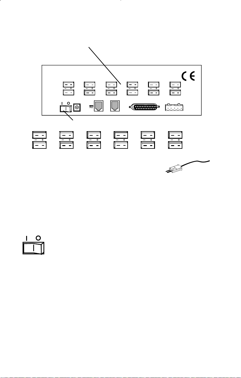
Installation
12 CHANNEL TERMOCOUPLE SCANNER
1
MODEL ####-##
Mfg. By Barnant Company
Barrington, IL 60010-2392
USA
1
7
2
8
10-28 VDC
7-20 VAC
500 MA
PC/IN
3
9
RS232
OUT/LINK
10
4
5
11
PARALLEL PRINTER
12
TRIGGER
6
+ GND
8256 4 7
1. Attach up to 12 thermocouples.
2. Connect the AC adapter to the instrument.
3. Plug the AC adapter into an outlet.
4 - 7 are Optional
4. Connect the PARALLEL PRINTER output to a PC printer (standard
parallel port cable - not supplied).
2
3
5. Connect the PC/IN jack to a serial port of your WINDOWS PC (use
the supplied cable).
6. To interconnect instruments connect the OUT/LINK jack of one
Scanning Thermocouple Ther mometer to the PC/IN jack of the next
(cable supplied).
7. To control printing or data storage by external events, connect
momentary contact events to the TRIGGER + GND connector.
8. Switch power switch to on.
12
Page 14
Front panel displays and controls
1 STORE button
MENU
EXIT
+-
ALARM
0
CLEAR
1
STORE
1
STORE2 LOG
1
3
RECALL
4
PRINT
5
MAX
6
MIN
.
7
AVG
°F
8
HOLD9SCAN
1 STORE button
Push to store one record cycle of the current set of readings in memory.
(Same as LOG, except only one record is stored.)
When a numerical entry is required and the NUM icon is on, push to
enter a ‘1’.
ab
°F
STORE
The word “STORE” a and the record number being stored b appear in
the display for about 3 seconds. Then the display returns to nor mal.
c
°F
4
STORE
“STORE” c appears, and remains in the display when one or more record
cycles are in storage (STORE and/or LOG).
Use to save a particular data record.
• A record includes readings from all 12 channels plus the time and
date.
• Up to 4,680 records may be stored. Memory is shared with LOG.
When no more data can be stored the display reads “STORE
FULL”.
• To clear (erase) stored records, push CLEAR, then push STORE.
“STORE” disappears from the display.
13
Page 15
Front panel displays and controls continued
2 LOG button
MENU
EXIT
+-
ALARM
0
CLEAR
1
STORE2 LOG
3
RECALL
4
PRINT
5
MAX
6
MIN
.
7
AVG
°F
8
HOLD9SCAN
2
2
LOG
2 LOG button
Push to log record cycles as they are read. (Same as STORE, only
continues automatically.)
When a numerical entry is required and the NUM icon is on, push to
enter a ‘2’.
Push again to turn logging off.
°F
4
LOG
a
The word “LOG” a appears and remains in the display while records are
being logged.
“STORE” appears, and remains, in the display when one or more records
are in storage.
Use to save a particular set of data records.
• Readings from all 12 channels are logged.
• How often records are logged is set using the MENU - LOG
procedure, page 37, which may be different from the scan rate.
• The time and date of the reading is logged.
• Up to 4,680 records may be logged. Memory is shared with the
STORE function. When no more data can be stored the display
reads “LOG FULL”.
• To clear (erase) stored records, push CLEAR, then push LOG.
“STORE” will disappear from the display.
14
Page 16
Front panel displays and controls continued
3 RECALL button
MENU
EXIT
+-
ALARM
0
CLEAR
3
1
STORE2 LOG
°F
.
3
4
PRINT
5
MAX
RECALL
3
6
MIN
7
AVG
8
HOLD9SCAN
RECALL
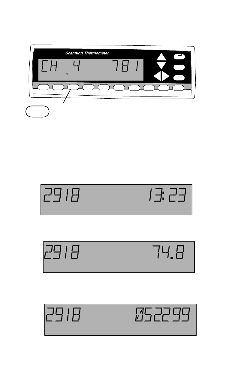
3 RECALL button
Push to recall stored (STORE or LOG) data.
When a numerical entry is required and the NUM icon is on, push to
enter a ‘3’.
• “RECALL” appears and remains in the display during recall.
• The LOG or STORE record number and time of channel 1 are
displayed first.
1
STORE RECALL
Push RECALL again to display the temperature.
1
STORE RECALL
Push RECALL again to display the date.
1
STORE RECALL
(continued on next page)
°F
15
Page 17
Front panel displays and controls continued
3 RECALL button continued
4 PRINT button
MENU
EXIT
+-
ALARM
0
CLEAR
1
STORE2 LOG
3
3
RECALL
4
PRINT
°F
.
7
6
5
MIN
MAX
4
AVG
8
HOLD9SCAN
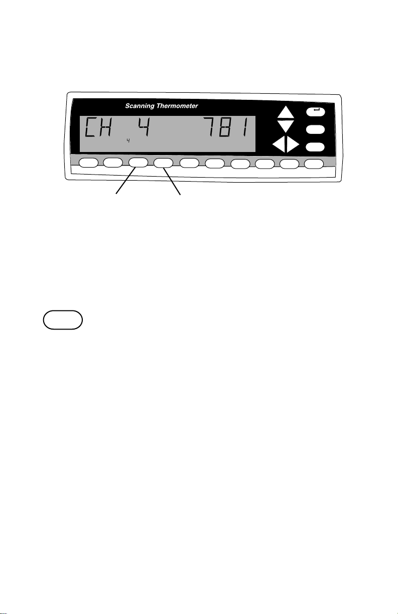
3 RECALL button continued
• Any time during RECALL push the Up-Down arrow keys to scroll
through the stored records.
• Any time during RECALL push the Left-Right arrow keys to scroll
through the channels.
• To exit RECALL push EXIT.
4
PRINT
4 PRINT button
Push to print on the printer attached to the PRINTER port. Push again to
stop printing.
When a numerical entry is required and the NUM icon is on, push to
enter a ‘4’.
• “PRINT” appears and remains in the display.
• Records are printed at intervals set in the MENU.
See MENU - How to adjust the print rate, see page 36.
• Push PRINT again to turn off printing.
Example printout:
11:59:48 CH 1: 72.9 CH 2: 75.7 CH 3: UNDER CH 4: 74.6
04/24/99 CH 5: 74.5 CH 6: 74.5 CH 7: 76.0 CH 8: 74.5
CH 9: 74.7 CH 10: 74.1 CH 11: 73.8 CH 12: 73.7
16
Page 18
Front panel displays and controls continued
5 MAX button
MENU
EXIT
+-
ALARM
0
CLEAR
1
STORE2 LOG
3
RECALL
4
PRINT
5
MAX
6
MIN
.
7
AVG
°F
8
HOLD9SCAN
5
5
MAX
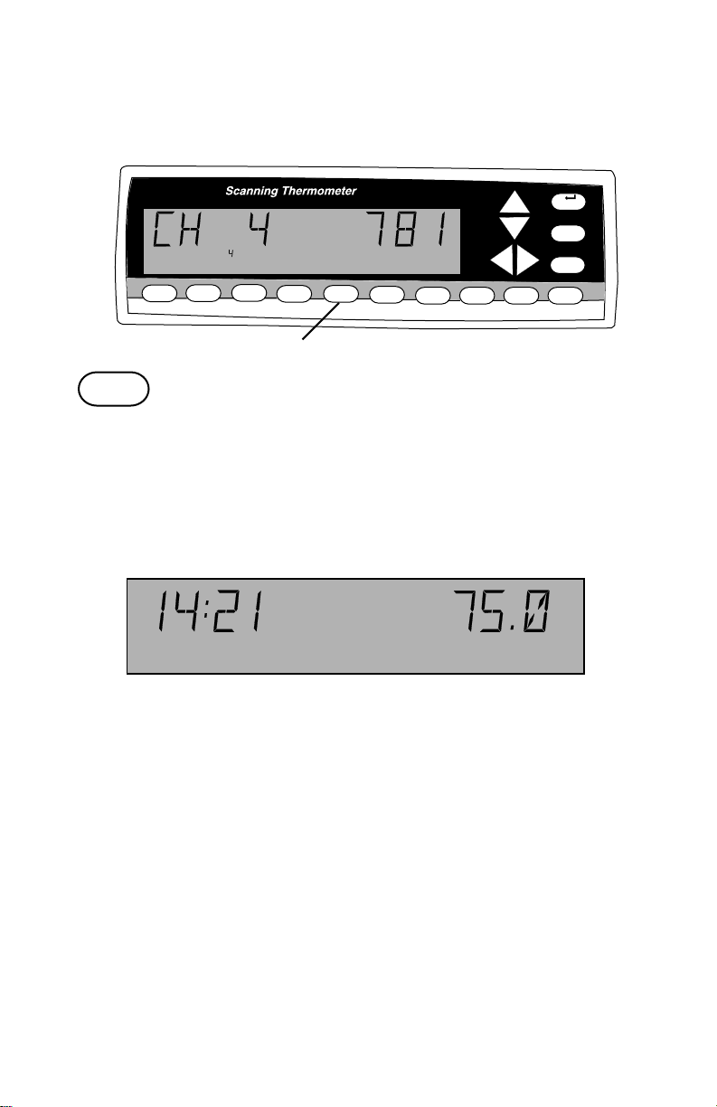
5 MAX button
Push to display the maximum temperature logged for each channel. The
display continues to scan channels.
When a numerical entry is required and the NUM icon is on, push to
enter a ‘5’.
°F
2
MAX
•“MAX” appears and remains in the display.
• The time and maximum reading for a channel are displayed (since
power up or last cleared).
• Push MAX again to switch between the time and the date.
• Use Left-Right arrow keys to stop scanning and to choose the
channel whose maximum value is displayed. Push SCAN to return
to scanning channels while remaining in MAX.
• Push MIN to switch the display to the minimum logged value of the
displayed channel.
• Push EXIT to exit.
17
Page 19
Front panel displays and controls continued
6 MIN button
MENU
EXIT
+-
ALARM
0
CLEAR
1
STORE2 LOG
3
RECALL
4
PRINT
5
MAX
6
MIN
.
7
AVG
°F
8
HOLD9SCAN
6
6
MIN
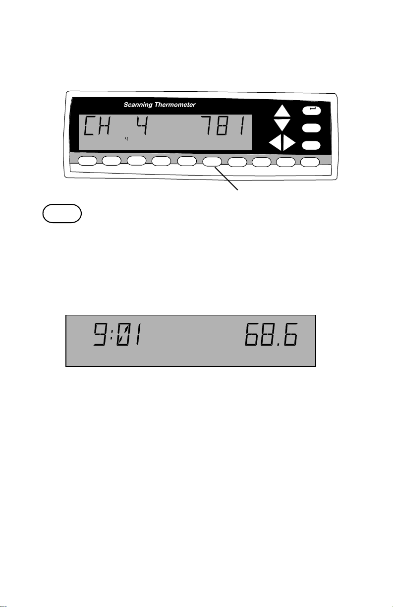
6 MIN button
Push to display the minimum temperature logged for each channel. The
display continues to scan channels.
When a numerical entry is required and the NUM icon is on, push to
enter a ‘6’.
°F
2
MIN
•“MIN” appears and remains in the display.
• The time and minimum reading for a channel are displayed (since
power up or last cleared).
• Push MIN again to switch between the time and the date.
• Use Left-Right arrow keys to stop scanning and to choose the
channel whose minimum value is displayed. Push and release
SCAN to return to scanning channels while remaining in MIN.
• Push MAX to switch the display to the maximum logged value of
the displayed channel.
• Push EXIT to exit.
18
Page 20
Front panel displays and controls continued
7 AVG button
8 HOLD button
MENU
EXIT
+-
ALARM
0
CLEAR
8
7
AVG
1
STORE2 LOG
3
RECALL
4
PRINT
5
MAX
6
MIN
7
.
7
AVG
°F
8
HOLD9SCAN
7 AVG button
Push to display the average temperature for each channel and the
number of readings that are being averaged. The display continues to
scan channels.
When a numerical entry is required and the NUM icon is on, push to
enter a ‘7’.
°F
5
AVG
•“AVG” appears and remains in the display.
• Readings from when the instrument was last powered up or
cleared are averaged.
• Opened channel readings are not averaged.
• Use Left-Right arrow keys to stop scanning and to choose the
channel whose average is displayed. Push SCAN to return to
scanning channels while remaining in AVG.
• Push AVG again to exit.
8
HOLD
8 HOLD button
Push to hold the current record in display.
When a numerical entry is required, and the NUM icon is on, push to
enter an ‘8’.
•“HOLD” appears and remains in the display.
• Channel scanning, logging, printing continue normally but the
display remains.
• Push HOLD or EXIT to exit.
19
Page 21
Front panel displays and controls continued
9 SCAN button
0 CLEAR button
MENU
EXIT
+-
ALARM
0
CLEAR
9
SCAN
1
STORE2 LOG
3
RECALL
4
PRINT
5
MAX
6
MIN
.
7
AVG
°F
8
HOLD9SCAN
9
9 SCAN button
Push to start a channel scan.
When a numerical entry is required and the NUM icon is on, push to
enter a ‘9’.
• Each channel is displayed for three seconds.
• Use to return to scanning after scanning is stopped by using the
Left-Right arrow keys.
• Causes an immediate scan.
0
CLEAR
0 CLEAR button
Push CLEAR, then push A VG, ALARM, MAX, MIN, STORE or LOG to
clear that value.
When a numerical entry is required and the NUM icon is on, push to
enter a ‘0’.
• CLEAR - AVG erases the 12-Channel record containing the
average temperature from memory.
• CLEAR - ALARM turns the alarm buzzer off, all alarm conditions,
error messages, and temperature out of range alarms. Normally
push ALARM when an alarm occurs, that stops the alarm buzzer
and checks the alarm condition.
• CLEAR - MAX erases the 12-Channel record containing the
maximum temperature from memory.
• CLEAR - MIN erases the 12-Channel record containing the minimum temperature from memory.
• CLEAR - STORE erases the 12-Channel records that have been
logged or stored in memory (= CLEAR - LOG).
• CLEAR - LOG erases the 12-Channel records that have been
logged or stored in memory (= CLEAR - STORE).
0
20
Page 22

Front panel displays and controls continued
MENU button
Up-Down Arrow keys
MENU
EXIT
+-
ALARM
0
CLEAR
MENU
1
STORE2 LOG
3
RECALL
4
PRINT
5
MAX
6
MIN
Up-Down Arrow Keys
.
7
AVG
°F
8
HOLD9SCAN
MENU
MENU button
Push to scroll through the menu to enter or change setup parameters.
The word “SCALE” appears in the display and the current scale setting
(for example °F) flashes.
To scroll backwards through the menu choices push and hold MENU
then press the Left arrow key.
See MENU, starting on page 26, for a complete selection of MENU
choices and how to set up parameters.
Up-Down Arrow keys
Active within the MENU. Used to scroll through menu options.
21
Page 23

Front panel displays and controls continued
Left-Right Arrow keys
°F
.
1
STORE2 LOG
Left-Right Arrow keys
Active within the MENU. Used to scroll through menu options.
• Manually select a channel.
3
4
PRINT
5
MAX
RECALL
Left-Right Arrow Keys
6
MIN
7
AVG
8
HOLD9SCAN
MENU
EXIT
+-
ALARM
0
CLEAR
22
Page 24

Front panel displays and controls continued
EXIT button
ALARM button
MENU
EXIT
+-
ALARM
0
CLEAR
EXIT
1
STORE2 LOG
EXIT
3
RECALL
4
PRINT
5
MAX
6
MIN
°F
.
7
AVG
ALARM
8
HOLD9SCAN
EXIT button
During MENU, push to EXIT the MENU and save any menu choices that
have been made. SAVING SETUP is displayed for two seconds, then the
instrument returns to scanning.
During STORE, RECALL, MAX, MIN, AVG, CLEAR or HOLD displays,
push to EXIT the display and return to scanning.
+ALARM
ALARM button
Push to turn off the alarm beeper. The flashing alarm icon and other
alarm displays remain.
When a numerical function is required and the NUM icon is on, push to
toggle between + and -.
°F
2
1
4
STORE
ALARM
2
Temperature Alarms
When an alarm occurs the alarm beeper will beep (if ALARM BEEPER is
set to ON in the menu) the printer will print the alarm record (if ALARM
PRINT ON is set in the menu), the alarmed channel 1 and the alarm icon
2 will flash.
(continued on next page)
23
Page 25

Front panel displays and controls continued
ALARM button continued
°F
2
4
STORE
ALARM
3
Temperature Alarms continued
• HI temperature alarm: When a thermocouple detects a tempera-
ture above the HI limit setting in the menu, ALARM is displayed,
the alarm icon and the channel number 3 flash. HI will flash when
that channel is displayed.
• LO temperature alarm: When a thermocouple detects a
temperature below the LO limit setting in the menu, ALARM is
displayed, the alarm icon, and the channel number 3 flash. LO will
flash when that channel is displayed.
To turn off the alarm displays: push the Left-Right arrow keys to
display the out of range channel, then push ALARM. Repeat for all
alarmed channels.
To clear all alarm conditions at once: push CLEAR then push ALARM.
24
Page 26

Front panel displays and controls continued
ALARM button continued
Other Alarms
• OPEN thermocouple: A thermocouple channel that is OPEN (no
thermocouple connected) will cause an OPEN alarm.
OPEN will be displayed instead of a temperature when that
channel is displayed.
Check thermocouple connection, wiring to the thermocouple, or
replace the thermocouple.
If the channel is not used, disable the channel (see How to Enable/
Disable channels, page 30).
• UNDER alarm: If the instrument detects a reading indicating a
temperature below the operating range of the thermocouple type
an UNDER alarm occurs.
UNDER will be displayed instead of a temperature when that
channel is displayed.
• OVER alarm: If the instrument detects a reading indicating a
temperature above the operating range of the thermocouple type
an OVER alarm occurs.
OVER will be displayed instead of a temperature when that
channel is displayed.
• LOG FULL alarm: 4,680 12-Channel records can be stored in
memory . A record is stored in memory manually by pushing
STORE, or automatically according to the log rate setting in the
menu.
During a LOG FULL alarm LOG and FULL alternate in the display.
During a LOG FULL alarm you can:
• RECALL - scroll through the logged readings.
• PRINT - print the logged readings.
To clear (erase) the memory: push CLEAR then push LOG.
• Instrument errors: Various hardware errors can also cause an
alarm such as an A/D error, EEPROM verify error, flash write error,
etc. The entire display will flash the alarm message. See Error
Messages, page 62.
Normal display updates stop until the alarm is acknowledged.
Other updates (scanning, printing, other alarms, logging) continue
without interruption.
25
Page 27

Front panel displays and controls continued
About the MENU
1
MENU
EXIT
+-
ALARM
0
CLEAR
MENU
°F
.
1
STORE2 LOG
3
RECALL
4
PRINT
5
MAX
6
MIN
7
AVG
8
HOLD9SCAN
About the Menu
Push the MENU button 1 to scroll through the menu to
enter or change setup parameters.
The word “SCALE” appears in the display and the current scale setting
(for example °F) flashes.
To scroll backwards through the menu choices push and hold MENU
then press the Left arrow key.
MENU lets you adjust the following:
display see page
SCALE temperature scale displayed .................. 28
RESOLUTION the resolution of the displayed
temperature........................................... 29
choose which channels are
scanned ................................................. 30
KKKKKK... thermocouple type ................................. 31
CONTRAST the contrast of the display ...................... 32
TRIGGER OFF trigger off/on........................................... 33
TRIGGER PULSE trigger mode ........................................... 34
SCAN scan time interval ................................... 35
RATE PRINT rate ............................................. 36
RATE LOG rate ................................................ 37
ALARM alarm off, or on....................................... 39
PRINT ON alarm print on or off................................. 40
If alarm is set to ON
choose channel to set HI alarm .............. 41
choose channel to set LO alarm ............. 42
HYST set alarm hysteresis ................................ 43
SETPT set HI alarm setpoints ............................. 44
SETPT set LO alarm setpoints ............................ 45
BEEPER beeper on or off...................................... 46
DATE MM/DD date format ............................................. 47
DATE 042599 set date .................................................. 48
TIME 10:13 set time .................................................. 49
CALPT 1 32.0 field calibration ....................................... 50
REPORT calibration report ..................................... 53
Page 28

Front panel displays and controls continued
About the MENU continued
About the Menu continued
• Quick access - Push MENU then SCAN, PRINT, LOG, or ALARM
to jump to that point in the menu.
• When done with a menu setup either push EXIT to save the setup
and return to scanning or push MENU to continue to the next menu
setup.
• If a numeric entry is required in a menu setup, a flashing NUM icon
is displayed and the number and ± keys are active.
• To erase a single digit while entering a number push the Down
arrow key.
Page 29

Front panel displays and controls continued
How to set the scale
°F
How to set the scale
The instrument can record, display and print at the following scales:
°F Degrees Fahrenheit
°C Degrees Centigrade
°R Degrees Rankin
K Kelvin
The default scale is °F.
5
MAX
6
MIN
1b
7
AVG
°F
8
HOLD9SCAN
1a
1
STORE2 LOG 3RECALL
4
PRINT
To set or change the scale:
1. Push MENU, SCALE 1a is displayed and the current scale
setting 1b flashes.
2. Push the Up or Down arrow keys until the desired scale is
flashing.
3a. Push EXIT to save the setup and return to scanning, or
3b. Push MENU to switch to the next setup topic (adjust
the resolution).
2 1, 3b
MENU
EXIT
+-
ALARM
0
CLEAR
3a
Page 30

Front panel displays and controls continued
How to change the resolution
How to change the resolution
The instrument can display and print temperatures at either 0.1° or 1°
resolution.
The default resolution is 0.1°.
1a
1
STORE2 LOG 3RECALL
4
PRINT
5
MAX
1b
6
MIN
7
AVG
8
HOLD9SCAN
2 1, 3b
MENU
EXIT
+-
ALARM
0
CLEAR
To set or change the resolution:
1. Push MENU until RESOLUTION is displayed.
RESOLUTION 1a is displayed and the current resolution setting
1b flashes.
2. Push the Up or Down arrow keys until the desired resolution is
flashing.
3a. Push EXIT to save the setup and return to scanning, or
3b. Push MENU to switch to the next setup topic (Enable/Disable
channels).
3a
Page 31

Front panel displays and controls continued
How to Enable/Disable channels
1 2 3 4 5 6 7 8 9 10 11 12
How to Enable/Disable channels
A thermocouple channel can be turned off if that channel is not used or
not desired. A channel that is turned off will be skipped in a scan and
listed as OFF in a printout.
The default setting is all channels ON.
1a
1 2 3 4 5 6 7 8 9 10 11 12
1
STORE2 LOG 3RECALL
4
PRINT
5
MAX
3 2 1, 4b
7
AVG
8
HOLD9SCAN
6
MIN
MENU
EXIT
+ALARM
0
CLEAR
To set or change scan channels:
1. Push MENU until 1’s and 0’s are displayed and the current
channel 1a flashes. (1 is scan channel on, 0 is scan channel off.)
2. Push the Up or Down arrow keys as the channel flashes to
toggle between 1 and 0.
3. Push Left or Right arrow keys to switch channels.
Repeat steps 2 and 3 for all channels you want to change.
4a. Push EXIT to save the setup and return to scanning, or
4b. Push MENU to switch to the next setup topic (setup thermo-
couple types).
4a
Page 32

Front panel displays and controls continued
How to setup thermocouple types
123456789101112
How to setup thermocouple types
Thermocouples of types K, J, B, N, S, R, E or T can be used with this
instrument. Any combination of thermocouple types can be used.
See Appendix B for thermocouple specifications.
The default setting for all channels is type K.
1a
1 2 3 4 5 6 7 8 9 10 11 12
1
STORE2 LOG 3RECALL
4
PRINT
5
MAX
2 3 1, 4b
7
6
MIN
AVG
8
HOLD9SCAN
MENU
EXIT
+ALARM
0
CLEAR
To set or change thermocouple type:
1. Push MENU until K’s (or other types) are displayed and the
current channel 1a flashes (disabled channels are blank).
2. Push Left or Right arrow keys to switch channels.
3. Push the Up or Down arrow keys as the channel flashes to scroll
through thermocouple types.
Repeat steps 2 and 3 for all thermocouple type changes.
4a. Push EXIT to save the setup and return to scanning, or
4b. Push MENU to switch to the next setup topic (adjust the display
contrast).
4a
Page 33

Front panel displays and controls continued
How to adjust the display contrast
How to adjust the display contrast
The display contrast can be adjusted from 1 (very dark - the background
interferes with the display) to 50 (very light - display letters and numbers
are dim). This setting adjusts the contrast for varying viewing angles.
The default setting is 25.
1a
1
STORE2 LOG 3RECALL
4
PRINT
5
MAX
1b
6
MIN
7
AVG
8
HOLD9SCAN
2 1, 3b
MENU
EXIT
+ALARM
0
CLEAR
To set or adjust the display contrast:
1. Push MENU until CONTRAST 1a is displayed and the current
contrast value 1b flashes.
2. Push and hold the Up or Down arrow keys to adjust the contrast
value quickly. Push an Up or Down arrow key to change contrast
one digit at a time.
The contrast changes as the value is adjusted.
3a. Push EXIT to save the adjustment and return to scanning, or
3b. Push MENU to switch to the next setup topic (set trigger type).
3a
32
Page 34

Front panel displays and controls continued
a
How to set trigger type
How to set trigger type
A trigger (contact between pins 1 and 2 of the trigger) can be set to:
• pulse print (print one record when trigger contact is closed).
• S/S (start/stop) PRINT (equivalent to toggling PRINT on while
trigger contact is closed).
• pulse STORE (equivalent to pushing STORE to log one record).
• S/S (start/stop) STORE (equivalent to pushing LOG to continuously log records while trigger contact is closed).
The default setting is OFF.
2
1a
1b
1, 3b
MENU
EXIT
+ALARM
1
STORE2 LOG 3RECALL
4
PRINT
5
MAX
6
MIN
7
AVG
8
HOLD9SCAN
0
CLEAR
To set or adjust the trigger type:
1. Push MENU until TRIGGER 1a is displayed and the current
setting 1b (OFF, STORE or PRINT) flashes.
2. Push the Up or Down arrow keys to scroll between OFF, STORE
and PRINT.
3a. Push EXIT to save the setting and return to scanning, or
3b. Push MENU to switch to the next setup topic (set trigger mode).
3
33
Page 35

Front panel displays and controls continued
How to set trigger mode
How to set trigger mode
If a trigger type is set to PRINT or STORE, the trigger mode can be set.
(See How to set trigger type on preceding page.)
The modes are PULSE (momentary action, as in pushing and releasing a
button), and S/S (start/stop, toggle action as in switching on or off).
The default setting is PULSE.
1a
1
STORE2 LOG 3RECALL
4
PRINT
1b
5
MAX
6
MIN
7
AVG
8
HOLD9SCAN
2
1, 3b
MENU
EXIT
+ALARM
0
CLEAR
To set or adjust the trigger mode:
1. Push MENU until TRIG’R 1a is displayed and the current setting
1b (PULSE or S/S) flashes.
2. Push the Up or Down arrow keys to switch between PULSE and
S/S.
3a. Push EXIT to save the setting and return to scanning, or
3b. Push MENU to switch to the next setup topic (adjust the scan rate).
3a
34
Page 36

Front panel displays and controls continued
How to adjust the scan rate
NUM
How to adjust the scan rate
The scan rate is the interval between the start of individual scans of all
twelve channels.
The default setting is 00:04 (4 seconds).
It takes 4 seconds to do one 12 channel scan, so a scan rate of 00:04
results in continuous scanning.
With the scan rate at 00:20 there will be 3 scans per minute.
The maximum scan rate that can be set is one hour (60:00).
1a
1b
1, 3b
MENU
EXIT
NUM
1
STORE2 LOG 3RECALL
1c
4
PRINT
5
MAX
7
6
MIN
AVG
8
HOLD9SCAN
2
+ALARM
0
CLEAR
To adjust the scan rate:
1. Push MENU until SCAN is displayed or push MENU at least
once, then push SCAN.
SCAN 1a is displayed and the current setting 1b flashes.
NUM 1c appears and flashes indicating number keys 2 are
active.
2. Push number keys 2 to enter the scan rate. (For example, 36:12
is entered by pushing 3 - 6 - 1 - 2.)
3a. Push EXIT to save the setting and return to scanning, or
3b. Push MENU to switch to the next setup topic (adjust the print
rate).
3a
35
Page 37

Front panel displays and controls continued
How to adjust the print rate
NUM
PRINT
How to adjust the print rate
The print rate is the time the instrument waits between printing
temperature scans on the attached printer.
A printer must be attached and turned on. The instrument only sends the
data, there is no alarm or storage of print information if the printer is
disconnected or turned off.
The PRINT button must be pushed and PRINT displayed.
The default setting is 00:20 (20 seconds).
It takes 4 seconds to do one 12 channel scan so a print rate of 00:04 is the
maximum obtainable.
Note: If the print rate is set more often than the scan rate (lower time
setting) the instrument will scan and print at the print rate.
1a
NUM
1
STORE2 LOG 3RECALL
PRINT
4
PRINT
1b
5
MAX
6
MIN
7
AVG
8
HOLD9SCAN
MENU
EXIT
+ALARM
0
CLEAR
1, 3b
3a
1d
1c
2
To adjust the print rate:
1. Push MENU until the PRINT RATE displays or push MENU at
least once, then push PRINT.
RATE 1a is displayed and the current setting 1b flashes.
PRINT 1c is displayed.
NUM 1d appears and flashes indicating number keys are active.
2. Push number k e ys 2 to enter the print rate. (For example, 36:12 is
entered by pushing 3 - 6 - 1 - 2.)
3a. Push EXIT to save the setting and return to scanning, or
3b. Push MENU to switch to the next setup topic (adjust the log rate).
36
Page 38

Front panel displays and controls continued
How to adjust the log rate
NUM
How to adjust the log rate
The log rate is the time the instrument waits between logging temperature
scans in memory .
4,680 12 channel scans can be logged in memory , then LOG FULL is
displayed. When LOG FULL is displayed you can RECALL – scroll through
the logged readings, and you can PRINT – print the entire list of 4,680
logged entries. To clear (erase) memory: push CLEAR, then push LOG.
The default setting is 00:20 (20 seconds).
It takes 4 seconds to do one 12 channel scan so a log rate of 00:04 is the
maximum obtainable. The longest interval that can be set is 1 hour, 60:00.
LOG
Examples: At a setting of (00:20) the log is full in 26 hours . At the minimum setting (00:04) the log is full in 5.2 hours. For 8 hours use a setting of
00:09. At the maxim um setting (60:00) the log is full in 4,680 hours (195
days).
Manually pushing STORE adds one scan to the same memory as LOG.
(continued on next page)
37
Page 39

Front panel displays and controls continued
How to adjust the log rate continued
LOG
4
PRINT
1b
5
MAX
2
6
MIN
7
AVG
8
HOLD9SCAN
MENU
EXIT
+ALARM
0
CLEAR
1a
NUM
1
STORE2 LOG 3RECALL
1d
1c
To adjust the log rate continued:
1. Push MENU until the LOG RATE displays or push MENU at least
once, then push LOG. RATE 1a is displayed and the current
setting 1b flashes. LOG 1c is displayed. NUM 1d appears and
flashes indicating number keys 2 are active.
2. Push number keys to enter the log rate. (For example, 36:12 is
entered by pushing 3 - 6 - 1 - 2.)
3a. Push EXIT to save the setting and return to scanning, or
3b. Push MENU to switch to the next setup topic (set the alarm
mode).
1, 3b
3a
38
Page 40

Front panel displays and controls continued
How to set the alarm mode
ALARM
How to set the alarm mode
The alarm mode can be ALARMS OFF, or ALARMS ON.
The default setting is ALARMS OFF.
In ALARMS OFF the instrument does not react to temperature extremes
with an alarm.
In ALARMS ON a HI or LO temperature alarm remains until manually
reset.
To set the alarm mode:
1b
2
1, 3b
3a
MENU
EXIT
+ALARM
0
CLEAR
1
STORE2 LOG 3RECALL
4
PRINT
5
MAX
6
MIN
ALARM
7
AVG
8
HOLD9SCAN
1a
1. Push MENU until ALARMS is displayed or push MENU at least
once then push ALARM.
ALARM 1a is displayed and the current setting 1b ALARMS OFF,
or ALARMS ON flashes.
2. Push Up/Down arrow keys to switch mode.
3a. Push EXIT to save the setting and return to scanning, or
3b. Push MENU to switch to the next setup topic (set alarm print).
How to set HI alarm(s)
The alarm mode must be ALARMS ON. If the alarm mode is ALARMS
39
Page 41

Front panel displays and controls continued
How to set the alarm print
ALARM
How to set the alarm print
Alarm print can be PRINT ON or PRINT OFF.
The default setting is PRINT ON.
When set to PRINT ON a record is printed on your attached printer when
an alarm event occurs.
1b
2
1, 3b
3a
MENU
EXIT
+ALARM
0
CLEAR
1
STORE2 LOG 3RECALL
4
PRINT
5
MAX
6
MIN
ALARM
7
AVG
8
HOLD9SCAN
1a
To set the alarm print:
1. Push MENU until ALARM 1a and PRINT 1b are displayed and the
current setting 1b (ON or OFF) flashes.
2. Push the Up/Down arrow keys to toggle between ON and OFF.
3a. Push EXIT to save the setting and return to scanning, or
3b. Push MENU to switch to the next topic (set HI alarm(s), if the alarm
mode is ALARMS OFF the next setup topic is Enable/Disable the
alarm beeper).
40
Page 42

Front panel displays and controls continued
123456789101112
OFF this setting is skipped in the MENU.
The default settings are all 0’s (HI alarm off).
To set HI alarm(s):
How to set HI alarm(s)
ALARM HI
1c
3
2
1, 4b
4a
MENU
EXIT
1 2 3 4 5 6 7 8 9 10 11 12
1
STORE2 LOG 3RECALL
4
PRINT
5
MAX
ALARM HI
6
MIN
7
AVG
8
HOLD9SCAN
+ALARM
0
CLEAR
1a 1b
1. Push MENU until ALARM 1a and HI 1b are displayed and the
current channel settings are indicated by 0’s – HI alarm off, 1’s –
HI alarm on, or blank if that channel is disabled.
The currently selected channel is flashing 1c.
2. Push Left/Right arrow keys to select the channel.
3. Push Up/Down arrow keys to switch between 0 and 1.
Repeat steps 2 and 3 for all HI alarms you wish to change.
4a. Push EXIT to save the settings and return to scanning, or
4b. Push MENU to switch to the next setup topic (set LO alarm(s)).
41
Page 43

Front panel displays and controls continued
How to set LO alarm(s)
123456789101112
ALARM LO
How to set LO alarm(s)
The alarm mode must be ALARMS ON. If the alarm mode is ALARMS
OFF this setting is skipped in the MENU.
The default settings are all 0’s (LO alarm off).
MENU
EXIT
+ALARM
0
CLEAR
1, 4b
1c
1 2 3 4 5 6 7 8 9 10 11 12
1
STORE2 LOG 3RECALL
4
PRINT
5
MAX
1a
6
MIN
1b
ALARM LO
2
7
AVG
3
8
HOLD9SCAN
To set LO alarm(s):
1. Push MENU until ALARM 1a and LO 1b are
displayed and the current channel settings are indicated by
0’s – LO alarm off, 1’s – LO alarm on, or blank if that channel is
disabled.
The currently selected channel is flashing 1c.
2. Push Left/Right arrow keys to select the channel.
3. Push Up/Down arrow keys to switch between 0 and 1.
Repeat steps 2 and 3 for all LO alarms you wish to change.
4a. Push EXIT to save the settings and return to scanning, or
4b. Push MENU to switch to the next setup topic (set hysteresis).
4a
42
Page 44

Front panel displays and controls continued
How to set alarm hysteresis
°F
NUM
ALARM
How to set alarm hysteresis
The alarm mode must be ALARMS ON. If the alarm mode is ALARMS
OFF this setting is skipped in the MENU.
Note: Defaults /settings are described in °F, the actual scale used is the
scale that was previously selected.
The default setting is 1.0°F.
Hysteresis can be any value from 0.0°F to 99.9°F.
Hysteresis is the ± temperature range before an alarm is out of range.
For example, if a HI alarm is set at 100° and hysteresis is set at 1°, that
channel’s temperature exceeds 100°, and alarms are set to ON, the
alarm will come on. The alarm will be automatically reset when the
channel’s temperature goes below 99°. If hysteresis was set at 5° the
alarm would be automatically reset when the channel’s temperature goes
below 95°.
5
MAX
1c
1, 3b
3a
+ALARM
0
CLEAR
MENU
EXIT
°F
ALARM
7
6
MIN
AVG
8
HOLD9SCAN
1a
NUM
1
STORE2 LOG 3RECALL
4
PRINT
1d
1b
2
To set alarm hysteresis:
1. Push MENU until HYST 1a, ALARM 1b and current hysteresis
value 1c (flashing) are displayed.
NUM 1d appears and flashes indicating number keys are active.
2. Push number keys to set hysteresis.
(For example, 02.3 is entered by pushing 0 - 2 - 3.)
3a. Push EXIT to save the setting and return to scanning, or
3b. Push MENU to switch to the next setup topic (adjust HI alarm
setpoints).
43
Page 45

Front panel displays and controls continued
How to adjust HI alarm setpoints
NUM
3
ALARM°FHI
How to adjust HI alarm setpoints
The alarm mode must be ALARMS ON. If the alarm mode is ALARMS
OFF this setting is skipped in the MENU.
Only channels whose HI alarms are set to 1 (on) can have their
setpoints changed.
1a
1c
2
1, 4b
4a
MENU
EXIT
NUM
1
STORE2 LOG 3RECALL
1b
1f
3
4
PRINT
To adjust a HI alarm setpoint:
3
5
MAX
1d
6
MIN
1e
ALARM°FHI
7
AVG
8
HOLD9SCAN
+ALARM
0
CLEAR
1. Push MENU until SETPT 1a, the channel number 1b, the
setpoint value 1c, ALARM 1d, and HI 1e are displayed.
NUM 1f appears and flashes indicating number keys 3 are
active.
2. Push Left/Right arrow keys to select channel(s).
3. Push number keys to set the HI alarm temperature.
(For example, 156.8 is entered by pushing 1 - 5 - 6 - 8.)
Repeat steps 2 and 3 for all HI alarm set points you wish to
adjust.
4a. Push EXIT to save the setting and return to scanning, or
4b. Push MENU to switch to the next setup topic (adjust LO alarm
setpoints).
44
Page 46

Front panel displays and controls continued
How to adjust LO alarm setpoints
NUM
5
ALARM°FLO
How to adjust LO alarm setpoints
The alarm mode must be ALARMS ON. If the alarm mode is ALARMS
OFF this setting is skipped in the MENU.
Only channels whose LO alarms are set to 1 (on) can have their
setpoints changed.
1a
NUM
1
STORE2 LOG 3RECALL
1f
1b
5
4
PRINT
1c
6
5
MIN
MAX
1d
3
1e
2
ALARM°FLO
7
AVG
8
HOLD9SCAN
MENU
EXIT
+ALARM
0
CLEAR
1, 4b
To adjust a LO alarm setpoint:
1. Push MENU until SETPT 1a, the channel number 1b, the
setpoint value 1c, ALARM 1d, and LO 1e are displayed.
NUM 1f appears and flashes indicating number keys 3 are
active.
2. Push Left/Right arrow keys to select channel(s).
3. Push number keys to set the LO alarm temperature.
(For example, -0.8 is entered by pushing 0 - 8 - 0 ±.)
Repeat steps 2 and 3 for all LO alarm setpoints you wish to
adjust.
4a. Push EXIT to save the setting and return to scanning, or
4b. Push MENU to switch to the next setup topic (Enable/Disable the
alarm beeper).
4a
45
Page 47

Front panel displays and controls continued
How to Enable/Disable the alarm beeper
How to Enable/Disable the alarm beeper
Beeper on allows audible warning of alarm condition. Beeper off prevents
audible warning. In either case, the icon will flash.
This turns the audible beeper on or off. When off and an alarm occurs,
only the flashing alarm icon is displayed.
The following will cause an alarm:
• Channel temperature higher than a HI alarm setpoint.
• Channel temperature lower than a LO alarm setpoint.
• Open thermocouple.
• Disconnected thermocouple (= open thermocouple).
• Log full.
• Hardware errors (error message will appear).
1a
1
STORE2 LOG 3RECALL
1b
4
PRINT
5
MAX
6
MIN
7
AVG
2
8
HOLD9SCAN
MENU
EXIT
+ALARM
0
CLEAR
1, 3b
To Enable/Disable the alarm beeper:
1. Push and release MENU until BEEPER 1a, and ON or OFF 1b,
are displayed with ON or OFF flashing.
2. Push the Up/Down arrow keys to switch between ON and OFF.
3a. Push EXIT to save the setting and return to scanning, or
3b. Push MENU to switch to the next setup topic (set date format).
46
3a
Page 48

Front panel displays and controls continued
How to set the date format
How to set the date format
The date can be displayed MM/DD or DD/MM.
1a
1
STORE2 LOG 3RECALL
1b
4
PRINT
5
MAX
6
MIN
7
AVG
2
8
HOLD9SCAN
MENU
EXIT
+ALARM
0
CLEAR
1, 3b
To set the date format:
1. Push MENU until the word DATE 1a is displayed and the current
setting 1b flashes.
2. Push the Up or Down arrow keys to toggle between MM/DD and
DD/MM.
3a. Push EXIT to save the setting and return to scanning, or
3b. Push MENU to switch to the next setup topic (set the date).
3a
47
Page 49

Front panel displays and controls continued
How to set the date
NUM
How to set the date
The date can be displayed MM/DD/YY or DD/MM/YY. Check the date
format (previous page) before setting the date.
The internal calendar is ‘smart’. It automatically adjusts for months with
28, 30 and 31 days, and even compensates for leap year.
1a
NUM
1
STORE2 LOG 3RECALL
1c
1b
4
PRINT
MENU
EXIT
+ALARM
7
6
5
MAX
MIN
AVG
8
HOLD9SCAN
0
CLEAR
2
To set the date:
1. Push MENU until the word DATE 1a is displayed and the
current setting 1b flashes.
NUM 1c is flashing to indicate that number keys 2 are active.
2. Use number keys to enter the correct date.
(To enter 04-28-99 push 0 - 4 - 2 - 8 - 9 - 9.)
3a. Push EXIT to save the setting and return to scanning, or
3b. Push MENU to switch to the next setup topic (set the time).
1, 3b
3a
48
Page 50

Front panel displays and controls continued
How to set the time
NUM
How to set the time
The time must be set as 24-hour time. For times after 12:59 p.m. add 12
to the hours. Thus, 2:22 p.m. is 14:22, and 5:00 p.m. is 17:00.
4
PRINT
2
1b
5
MAX
6
MIN
7
AVG
8
HOLD9SCAN
MENU
EXIT
+ALARM
0
CLEAR
1, 3b
1a
NUM
1
STORE2 LOG 3RECALL
1c
To set the time:
1. Push MENU until TIME 1a is displayed and the current setting 1b
flashes.
NUM 1c is flashing to indicate that number keys 2 are active.
2. Use number keys to enter the correct time.
(To enter 18:21 push 1 - 8 - 2 - 1.)
3a. Push EXIT to save the setting and return to scanning, or
3b. Push MENU to switch to the next setup topic (field calibration).
3a
49
Page 51

Front panel displays and controls continued
How to do a field calibration
°F
NUM
5
CAL
How to do a field calibration
Factory calibration is stored in protected, non-volatile memory. Field
calibration is usually used to reduce probe errors over a specified range.
All field calibration values may be cleared (returning the instrument to
factory calibration) by pushing and holding CLEAR during the power up
display test.
An individual channel's field calibration may be cleared. When CALPT1
is displayed, press and hold CLEAR until CALPT1 CLR is displayed. This
also clears CALPT2 for this same channel. The CAL icon will also go off
for this channel.
There are no restrictions on what values may be entered for field
calibration.
Two calibration points may be entered for each channel. After CALPT1 is
entered the prompt for CALPT2 appears.
If only CALPT1 is entered the offset is affected.
If both CALPT1 and CALPT2 are entered, both slope and offset are
affected.
(See calibrating to the freezing/boiling points of water on page 53, for an
example.)
(continued on next page)
50
Page 52

Front panel displays and controls continued
How to do a field calibration continued
NUM
1
STORE2 LOG 3RECALL
2e
2a
2d
5
4
PRINT
3
5
MAX
2b
CAL
6
MIN
2c
7
AVG
4
MENU
°F
8
HOLD
9
SCAN
EXIT
+ALARM
0
CLEAR
To do a field calibration continued:
1. Place the probe(s) at the desired temperature.
2. Push and release MENU until the display reads CALPT1, 2a.
The entry point 2b flashes.
CAL 2c is displayed. The channel number 2d is displa yed.
NUM 2e appears and flashes indicating number keys 3 are active.
3. Push number keys to enter the temperature of the first calibration
point. (For example, 32.0 is entered by pushing 3 - 2 - 0.)
4. Use Left/Right keys to select ne xt channel. Do all CALPT1's first.
5. Push MENU to switch to CALPT2.
CALPT 2 is skipped if no changes are made in CALPT1.
2, 5
MENU
NUM
1
STORE2 LOG 3RECALL
°F
5
4
PRINT
5
MAX
CAL
6
MIN
7
AVG
8
HOLD9SCAN
EXIT
+ALARM
0
CLEAR
7
6. Place the probe(s) at the desired temperature.
7. Push and release number keys 7 to enter the temperature of the
second calibration point. (For example, 212.0 is entered by
pushing 2 - 1 - 2 - 0.)
(continued on next page)
51
Page 53

Front panel displays and controls continued
How to do a field calibration continued
9b
MENU
EXIT
9
SCAN
+ALARM
0
CLEAR
PRINT CAL
1
STORE2 LOG 3RECALL
4
PRINT
5
MAX
6
MIN
7
AVG
8
HOLD
To do a field calibration continued:
8. Push Left or Right arrow keys to switch channels and enter their
CALPT2, or if desired,
9a. Push EXIT to save the setting and return to scanning, or
9b. Push MENU to switch to the next setup topic (cal report).
9a
8
52
Page 54

Front panel displays and controls continued
How to print a calibration report
Note: This is only valid if an optional parallel printer is attached to the
DB-25 (M) input connection. Alternately, this report may be obtained
through “ScanLink”.
1b
2
1a, 3a
1c, 3b
PRINT CAL
1
STORE2 LOG 3RECALL
4
PRINT
5
MAX
6
MIN
7
AVG
8
HOLD
9
SCAN
MENU
EXIT
+ALARM
0
CLEAR
To print a calibration report:
1. If MENU 1a is pushed the display REPORT NO with NO 1b
flashing appears. Push MENU 1a or EXIT 1c to skip printing a
calibration report, or
2. Push either of the Up or Down arrow keys 2 to choose to print a
calibration report.
3. Push MENU 3a or EXIT 3b to save the setup (all setup changes
since MENU was first pushed), print the calibration report (if YES
was chosen) and return to scanning.
Example field calibration report °C:
Note: Service field calibration can only be performed by an authorized
service facility. Contact your authorized dealer for information.
Service calibration performed on 04/09/98 at 13:28:47
Field calibration status as of 04/09/98 14:11:50, scale = C
Ch CalPt.1 Change CalPt.2 Change Date Time
------- ------ ------- ------ -------- -------1 None 0.0 None 0.0 04/09/98 14:01:45
2 -16.7 0.0 482.3 0.0 04/09/98 13:58:51
3 -16.1 0.0 482.4 0.4 04/09/98 13:58:51
4 -15.5 0.1 482.5 0.2 04/09/98 13:58:51
5 -15.0 0.1 482.5 0.2 04/09/98 13:58:51
6 -14.4 0.1 482.6 0.4 04/09/98 13:58:51
7 -13.9 0.1 482.6 0.3 04/09/98 13:58:51
8 -13.3 -0.1 482.7 0.6 04/09/98 13:58:51
9 -12.8 0.0 482.7 0.5 04/09/98 13:58:51
10 -12.2 0.0 482.8 0.5 04/09/98 13:58:51
11 -11.7 0.0 482.8 0.6 04/09/98 13:58:51
12 -11.1 0.0 482.9 0.7 04/09/98 13:58:51
53
Page 55

Front panel displays and controls continued
How to print a calibration report continued
To print a calibration report continued:
Example field calibration report °F:
Service calibration performed on 04/09/98 at 13:28:47
Field calibration status as of 04/09/98 14:12:41, scale = F
Ch CalPt.1 Change CalPt.2 Change Date Time
------- ------ ------- ------ -------- -------1 None 0.0 None 0.0 04/09/98 14:01:45
2 2.0 0.0 900.2 0.1 04/09/98 13:58:51
3 3.0 0.0 900.3 0.7 04/09/98 13:58:51
4 4.0 0.2 900.4 0.4 04/09/98 13:58:51
5 5.0 0.1 900.5 0.4 04/09/98 13:58:51
6 6.0 0.1 900.6 0.6 04/09/98 13:58:51
7 7.0 0.1 900.7 0.6 04/09/98 13:58:51
8 8.0 -0.2 900.8 1.0 04/09/98 13:58:51
9 9.0 0.0 900.9 1.0 04/09/98 13:58:51
10 10.0 0.0 901.0 0.9 04/09/98 13:58:51
11 11.0 0.0 901.1 1.1 04/09/98 13:58:51
12 12.0 0.0 901.2 1.2 04/09/98 13:58:51
54
Page 56

Front panel displays and controls continued
How to calibrate to water
How to calibrate to water
Ice Point
Calibrate CALPT1 to the freezing point of water (0°C or 32°F) by using
crushed ice made of distilled water. Immerse the probe in a flask
(insulated) filled with crushed ice and topped off with distilled water.
Add crushed ice to keep the flask full of crushed ice and water during
calibration.
Boiling Point
Calibrate CALPT2 to the boiling point of water (100°C or 212°F) by using
distilled water and correcting for altitude and barometric pressure. As a
rule of thumb the boiling point of water decreases 1°C or 1.8°F for every
1000 feet above sea level. Correction for barometric pressure is usually
required only in the case of severe high or low pressure weather conditions.
Note: This method is less accurate than using a dry block calibrator or a
thermocouple calibration furnace. Boiling point calibration is only recommended when this equipment is not available and two point calibration is
required.
55
Page 57

Power up modes
Power up modes are special ways to clear memory or defaults during
power up.
To activate a power up mode:
MODEL ####-##
Mfg. By Barnant Company
Barrington, IL 60010-2392
12 CHANNEL TERMOCOUPLE SCANNER
1
7
2
8
10-28 VDC
7-20 VAC
500 MA
PC/IN
3
9
RS232
OUT/LINK
10
4
5
11
PARALLEL PRINTER
USA
12
6
TRIGGER
+ GND
21
1. Turn off the power using the power switch on the back of the
instrument ( ).
2. Turn power back on ( ) and before the instrument completes the
display check,
2a. (before the small 12 turns off).
NUM HOLD MAX PRINT AVG LOG STORE RECALL CAL MIN ALARM LO HI
Push and hold:
CLEAR & MENU to clear a service calibration and revert
to factory calibration, or
56
11
12
°F
°C
°R
K
2a
Page 58

Power up modes continued
Maintenance
Care and cleaning
Push and hold: MIN & MAX to restore factory MENU defaults, or
Push and hold: MENU to display the firmware version.
Push EXIT or CLEAR to switch to the scanning display.
Care and Cleaning
Clean the case by using a mild detergent. Avoid immersion and
excess liquid.
57
Page 59

Maintenance
Battery
Battery
A lithium battery retains the date and time when power is off or the
instrument is disconnected from its power source.
At room temperature and with a new battery, memory will be retained for
over a year.
A BAD BATTERY error message is displayed if the battery voltage is low
and the battery needs replacement.
3V
Battery: Lithium button battery RAYOVAC
PANASONIC® type BR1225, only.
To replace the battery:
®
or
LITHIUM
BR1225
+
WARNING: Turn power off and
2.
completely disconnect
instrument.
Disconnect power
source, thermocouples,
CLEAR
0
ALARM
+-
EXIT
MENU
AVG8HOLD9SCAN
7
computer, links, and
printer.
FRONT
1. Use anti-static discharge procedures as in computer repair.
2. Remove four screws from
bottom of unit.
3. Turn instrument right side up and
lift top cover off.
4. Remove the battery by slipping it
forward from under its contact clip.
5. Replace the battery.
6. Replace the top cover.
7. Turn instrument upside down and replace the screws.
58
MIN
MAX
PRINT
6
5
4
STORE
LOG
RECALL
1
2
3
4.
Page 60

WARRANTY
The Manufacturer warrants this product to be free from significant deviations from published specifications. If repair or adjustment is necessary
within the warranty period, the problem will be corrected at no charge if it is
not due to misuse or abuse on your part, as determined by the Manufacturer. Repair costs outside the warranty period, or those resulting from product misuse or abuse, ma y be invoiced to you.
The warranty period for this product is noted on the Warranty Card.
PRODUCT RETURN
To limit charges and delays, contact the seller or Manufacturer for authorization and shipping instructions before returning the product, either within
or outside of the warranty period. When returning the product, please state
the reason for the return. For your protection, pack the product carefully
and insure it against possible damage or loss. An y damages resulting from
improper packaging are your responsibility.
TECHNICAL ASSIST ANCE
If you have an y questions about the use of this product, contact the Man ufacturer or authorized dealer.
We reserve the right to make improvements in design, constr uction and
appearance of our products without notice.
59
Page 61

Specifications
Operating Temperature
(for stated accuracy)........................ 18°C to 28°C (64°F to 82°F)
Operating Temperature
(useful range)................................... 0°C to 40°C (32°F to 104°F)
Storage temperature........................–40°C to 60°C (–40°F to 110°F)
Humidity (non-condensing) .................... 10 to 90%
Altitude ................................................. Less than 2000 m
Accuracy
Thermocouple types E,J,K,N,T
>–150°C................................... ±(0.1% of reading ±0.5°C)
±(0.1% of reading ±0.8°F)
<–150°C................................... ±(0.25% of reading ±1°C)
±(0.25% of reading ±2°F)
Thermocouple types B,R,S..............±(0.1% of reading ±2°C)
±(0.1% of reading ±4°F)
Resolution .............................................. 0.1° or 1°
(1° above 999.9°)
(1° below –150°C, –238°F)
Scales ................................................. °C / °F / K / °R
Isolation
thermocouple to thermocouple ........ 250 VRMS
thermocouple to rear panel..............250 VRMS
Thermocouple connections .................... Two-blade female mini-ANSI
Display update rate ................................ 3 seconds
Thermocouple read time ........................ 4 seconds to 60 minutes
Print time ................................................4 seconds to 60 minutes
Battery ................................................. Lithium BR1225, RAYOVAC
PANASONIC® only
Display .................................................LCD
12 0.7 in variable characters
30 fixed word/icons
Alarm level ............................................. 50 dBa
Power source
Line voltage .....................................10–28V DC (non-polarized)
@ ~ 300 mA
9–20V AC 50–400 Hz
(continued on next page)
@ ~ 500 mA
60
®
or
Page 62

Specifications continued
Typical power usage ........................ 10–28V DC (non-polarized)
Enclosure ............................................... molded ABS case
UL-94V0
chemical resistance ......................... withstands standard cleaning
solvents
Pollution Degree .............................. Pollution Degree 2/ IEC664
(Indoor use—lab, office)
ingress rating ................................... IP-32 per IEC 529
Printer
connector......................................... DB25 male
Trigger input ........................................... internal pull-up
5K ohms/5V DC
contact closure to ground
PC IN ................................................. RJ-11, RS-232
19,200 baud, 7-bit
odd parity
OUT LINK............................................... RJ-11, RS-232
19,200 baud, 7-bit
odd parity
Dimensions
L ⫻ W ⫻ H .......................................8.5 ⫻ 10.4 ⫻ 3.6 in
weight ..............................................~ 3 lbs.
Compliance (For CE Mark): ................... EN61010-1/A2: 1995
(EU Low Voltage Directive) and
EN61326-1/A1: 1998
(EMC Directive)
Use of external agency-listed
power converter reduces
voltages to non-hazardous
levels. Regulatory agency
specifications, therefore, are
not applicable to the balance of
the unit.
61
Page 63

Appendix A
Error messages
Error messages are listed in alphabetical order, followed by a brief
description of the error condition, followed by what action the user can
take to correct the error (if possible).
A/D TIMEOUT
Return for service if error persists.
BAD BATTERY
Low battery voltage. Affects the clock and calendar. Replace the lithium
battery inside the instrument. See pg. 58.
BAD FLD CAL
Bad field calibration checksum. All field calibration values are erased.
Repeat field calibration if needed.
BAD SRVC CAL
Bad service calibration checksum. Usually requires service or repair to
correct. Until then defaults to last factory calibration.
CHKSUM ERROR
Bad program checksum. Usually requires service or repair to correct.
CONFIG ERR
Power down to clear error. Return for service if error persists.
ERASE ERROR
Internal memory error. Usually requires service or repair to correct.
NO CAL
Bad factory calibration checksum. This information is stored in the
microprocessor’s EEPROM and has been partially erased. Pressing the
“ALARM” button will clear the error message and allow the unit to function
without calibration: The unit will not meet published accuracy, but it
will operate.
OPEN
The channel is detecting a missing or open (defective) probe.
OVER
The channel is detecting a temperature that is above the maxim um for
the selected thermocouple type.
SETUP ERROR
MENU setup items are invalid. Factory defaults are used. Repeat MENU
setup if needed.
UNDER
The channel is detecting a temperature that is below the minimum for the
selected thermocouple type.
VERIFY ERROR
Internal memory error. Usually requires service or repair to correct.
WRITE ERROR
Internal memory error. Usually requires service or repair to correct.
62
Page 64

Appendix B Guidelines to Thermocouple Selection
Type E
Temperature range................................. -250°C to 871°C
Environmental tolerance ........................ oxidizing, inert atmospheres.
Color ...................................................... violet, + lead violet, - lead red
Type J
Temperature range................................. 0°C to 760°C
Environmental tolerance ........................ vacuum, oxidizing, reducing or inert
Color ...................................................... black, + lead white, - lead red
Type K
Temperature range................................. -250°C to 1260°C
Environmental tolerance ........................ continuous use in oxidizing or inert
Color ...................................................... yellow, + lead yellow, - lead red
Type N
Temperature range................................. 0°C to 1250°C
Environmental tolerance ........................ continuous use in oxidizing or inert
Color ...................................................... orange, + lead orange, - lead red
Type T
Temperature range................................. -184°C to 371°C
Environmental tolerance ........................ vacuum, oxidizing reducing or inert
Color ...................................................... blue, + lead blue, - lead red
Type B
Temperature range................................. 870°C to 1700°C
Environmental tolerance ........................ oxidizing or inert atmospheres.
Color ...................................................... grey, + lead grey, - lead red
Type R
Temperature range................................. 0°C to 1480°C
Environmental tolerance ........................ oxidizing or inert atmospheres.
Color ...................................................... green, + lead black, - lead red
Type S
Temperature range................................. 0°C to 1480°C
Environmental tolerance ........................ oxidizing or inert atmospheres.
Color ...................................................... green, + lead black, - lead red
atmospheres.
atmospheres.
atmospheres.
atmospheres.
Appendix C Temperature Conversion
Fahrenheit - Centigrade Centigrade - Kelvin
One Fahrenheit degree is 5/9 of a K = °C - 273.18
Centigrade degree so the following °C = K + 273.18
formulas apply:
°F = (9/5)°C + 32 Fahrenheit - Rankin
°C = (°F - 32)(5/9) °R = °F + 459.67
°F = °R - 459.67
63
Page 65

Appendix D
Menu flow chart
Set
scale
Adjust
resolution
Enable/disable
channels
12345 6789101112
Setup thermocouple types
12345 6789101112
Adjust
contrast
Set trigger
type
off
°F
°F
Push MENU to proceed to
the next menu choice.
Push EXIT to exit and
save menu changes.
select
channel
select
channel
print or
store
Set trigger
type
STORE
Set trigger
mode
Push MENU & left arrow key
to go backwards in the
menu.
Set alarm
mode
ALARM
alarms
on
alarms off
Set alarm
print
ALARM
Alarm
beeper
Set date
format
Set
date
NUM
Set
time
NUM
Adjust scan
rate
NUM
Adjust print
rate
NUM PRINT
Adjust log
rate
NUM LOG
64
Field
calibration
5
NUM CAL
Calibration
report
PRINT
Exit menu
set
calpt1
°F
CAL
Page 66

alarms
on
Set alarm
print
ALARM
Appendix D continued
Menu flow chart
Push MENU to proceed to
the next menu choice.
Push MENU & left arrow
key to go backwards in
the menu.
Set HI
alarms
123456789101112
ALARM HI
Set LO
alarms
123456789101112
ALARM LO
Set alarm
hysteresis
NUM
ALARM
Set hi alarm
setpoints
3
NUM
ALARM HI
Set lo alarm
setpoints
8
ALARM LONUM
select
channel
select
channel
°F
Push EXIT to exit and
save menu changes.
Set calibration
point 1
5
NUM CAL
°F
Set calibration
point 2
5
NUM CAL
°F
select
channel
select
channel
Calibration
select
channel
°F
report
PRINT
CAL
Exit menu
select
channel
°F
if set
calpt1
65
Page 67

Appendix E
Factory Default settings
A variety of parameters are user set-able using the MENU.
Your menu settings are retained in memory even when the instrument is
turned off or disconnected from a power source.
When the unit is first turned on, the memory contains the factory default
menu settings. To erase all the menu settings and reset the instrument to
factory default menu settings:
1. Turn off the power using the power switch on the back of the
instrument.
2. Turn power back on, and before the instrument completes the
display check (before the small 12 turns off).
3. Push and hold MIN and MAX.
Menu function Setting
Scale ..............................................................................°F
Resolution......................................................................... 0.1°
Scan channels ................................................................all on
Thermocouple types ............................................................. K
Display contrast .................................................................. 25
Trigger mode .....................................................................S/S
Trigger type......................................................................... off
Scan rate ........................................................................00:04
Print rate .........................................................................00:20
Log rate .........................................................................00:20
Alarm
Alarm mode.................................................................. off
Alarm print.................................................................... on
HI alarm channel select ........................................... 1 (on)
LO alarm channel select .......................................... 1 (on)
Alarm hysteresis ....................................................... 1.0°F
HI alarm setpoint (on/off) .............................................. off
HI alarm setpoint .................................................. 212.0°F
LO alarm setpoint (on/off) ............................................. off
LO alarm setpoint ................................................... 32.0°F
Alarm beeper................................................................ off
Date format ...................................................................mm/dd
Date ......................................................................factory*
Time ......................................................................factory*
*Date and time are set at factory, USA central time.
Field Calibration
CALPT 1 ................................................................ input**
CALPT 2 ................................................................ input**
**Instrument display shows current input reading.
Calibration report .......................................................... no
66
 Loading...