

Page 1
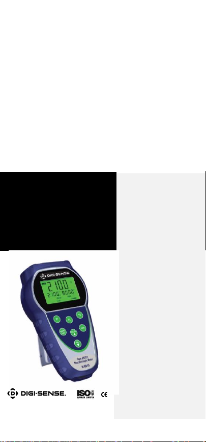
Instruction Manual
Dual-Input J/K/T/E Thermocouple
Thermometer (Model 91428-03)
Dual-Input Data Logging
Thermocouple Thermometer
(Model 91428-04)
68X001352 Rev0 0717 1065DGMAN_91428-03,-04
Page 2

TABLE OF CONTENTS
1. INTRODUCTION ..................................... 1
2. SAFETY PRECAUTIONS ........................ 2
3. SPECIFICATIONS .................................. 3
4. BATTERY INSTALLATION ...................... 6
5. OPTIONAL RUBBER ARMOR .................. 7
6.
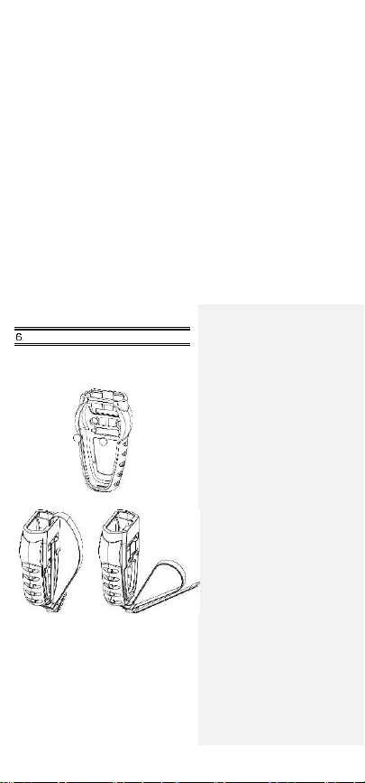
OPTIONAL HANDS-FREE KIT
.................. 8
7. CONNECTING A THERMOCOUPLE ........ 9
8. KEY FUNCTIONS ................................. 11
9. DISPLAY OVERVIEW ........................... 12
10. MEASUREMENT MODE........................ 13
11. HOLD FUNCTON .................................. 14
12. MIN, MAX, AND AVG FUNCTION ............ 14
13. DATA LOGGING ................................... 14
14. SETUP MODE ...................................... 15
15. GENERAL SETUP SCREEN ................. 16
16.
CALIBRATION SCREEN
........................ 18
17.
ALARMS SCREEN
................................ 21
18. DATA LOGGING SCREEN .................... 22
19.
CALIBRATION REPORT SCREEN
......... 23
20. CLEAR / RESET SCREEN..................... 24
21.
MAINTENANCE
.................................... 25
22.
CLEANING
........................................... 25
23.
BATTERIES
.......................................... 25
24. TROUBLESHOOTING ........................... 26
25.
ACCESSORIES
.................................... 27
26.
WARRANTY
......................................... 28
27.
PRODUCT RETURN
............................. 28
28. INNOCAL
®
CALIBRATION AND
REPAIR SERVICES .............................. 29
Page 3
- 1 -
INTRODUCTION
This versatile handheld
instrument provides highly
accurate temperature
measurements. The
instrument is designed
for easy operation and
includes the following
features:
• Menu driven setup and operation
• Data logging for up to 1000 points
on model 91428-03, 2000 points
on model 91428-04
• USB output (model 91428-04 only)
• Differential temperature
measurements
• Operator selection of Celsius or
Fahrenheit scale
• Resolution of 0.1°C/F from
–199.9 to 999.9°
• Large backlit LCD with two lines
of four-digit display
• Hold feature for temporarily retain
a reading
• Displays min and max readings
• Field calibration capability
• Disabling of Auto-Off function
• Low-battery warning
• Two blade female ANSI mini-
connector input
• Operates with a wide selection of
probes
Page 4

- 2 -
SAFETY PRECAUTIONS
WARNING:
1. This instrument is designed to
accept low level signals supplied
by standard Thermocouples. Under
NO circumstances should the input
voltage exceed the specified
50V RMS.
2. To prevent ignition of a hazardous
atmosphere, batteries must only be
changed in an area known to be
nonhazardous.
CAUTION:
1. Do not use or store this instrument in
microwave ovens or any abnormally
hot or cold areas.
2. Weak batteries should not be left in
the instrument. Dead batteries can
leak and cause damage to unit.
DANGER:
1. Voltages present at the
thermocouple may also be present
at the battery terminals. Always
disconnect the thermocouple when
changing batteries.
Page 5
- 3 -
SPECIFICATIONS
Thermocouple Thermometers
Type
Temperature range
Type J
–210°C to 1200°C
(–346°F to 2192°F)
Type K
–250°C to 1372°C
(–418°F to 2501°F)
Type T
–250°C to 400°C
(–418°F to 752°F)
Type E
–250°C to 1000°C
(–418°F to1832°)
Type R (model
91428-04 only)
0°C to 1768°C
(32°F to 3214°F)
Type S (model
91428-04 only)
0°C to 1768°C
(32°F to 3214°F)
Type N (model
91428-04 only)
–250°C to 1300°C
(–418°F to 2372°F)
Type B (model
91428-04 only)
200°C to 1800°C
(392°F to 3272°F)
Out-of-range display: - - -
-
Reso
lution:
0.1°/1° auto-ranging,
0.1°C/F from –199.9 to 999.9°,
1° outside this range
Page 6

- 4 -
Accuracy:
Types J, K, T, E, and N:
Below –150°C (–238°F):
±0.25% of reading ±1°C (±0.25% ±0.7°F)
Above –150°C (–238°F):
±0.1% of reading ±0.4°C (±1% ±0.7°F)
Types R, S, and B:
±0.1% of reading ±1°C (±0.1% ±2°F)
Display:
Backlit dot matrix, 50mm x 37.2mm
Data logging:
Model 91428-03: 1000 points
Model 91428-04: 2000 points
Logging interval:
1 sec to 60 min
Min/Max/Avg function:
Yes
Auto Off (adjustable time):
Enable/disable option available
Stability criteria:
Yes, upon stability of 5 seconds
Display update
rate:
0.6
sec per up
date
Input:
Two thermocouples with ANSI connector
Page 7

- 5 -
Input protection:
50V
rms
Storage:
–40°C to 65°C (–40°F to 149°F)
Humidity:
10% to 90% RH (noncondensing)
Battery life:
Size: Three AA, 1.5V; alkaline
Life: 400 hours continuous, typical,
(without backlighting)
Dimensions:
Without armor:
175mm (L) X 97mm (W) X 42mm (H)
With armor:
180mm (L) X 102mm (W) X 52mm (H)
Weight with batteries:
Without armor: 267g
With armor: 362g
Ingress protection:
Meets IEC-529 IP-54 for dust and water
resistant enclosures (probe attached)
CE Compliance:
EN61326-1/A1: 1998 (EU EMC Directive)
Page 8

- 6 -
BATTERY INSTALLATION
The total battery life without backlighting
and alarm is about 400 hours. The
battery bar annunciator represents the
battery strength. An empty battery
annunciator indicates low battery
strength; a blinking battery annunciator
indicates that the batteries should be
replaced immediately.
Selected settings are stored in memory
and will remain in memory even after
power is turned off, or while batteries
are being replaced.
1. Before changing battery, turn
instrument off and disconnect
thermocouple.
2. Loosen screw and lift battery cover
off back of case.
3. Remove the three AA batteries.
4. Insert three new batteries
observing polarity.
5.
Install cover and tighten screw.
Page 9
- 7 -
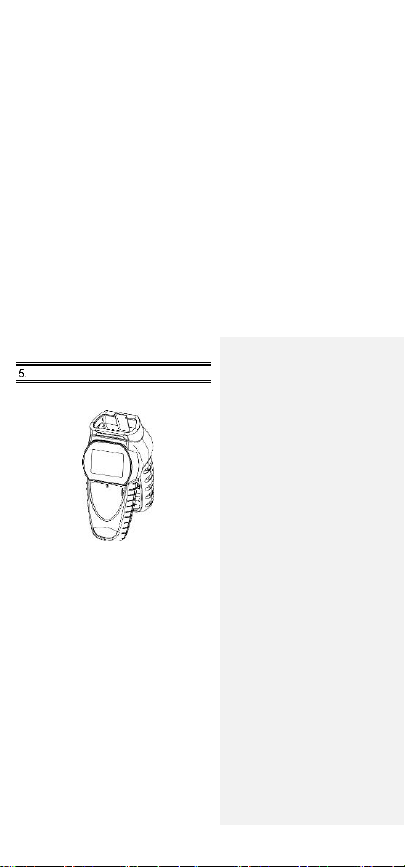
RUBBER ARMOR
1. To insert thermometer into the
optional rubber armor, slide in from
the top of meter before pushing the
bottom edges of meter down to set
it into position. Lift up the stand at
the back of meter for bench top
applications if necessary.
2. To remove thermometer from armor,
push out from the bottom edges of
meter until it is completely out of boot.
Page 10
- 8 -
OPTIONAL HANDS-FREE KIT
You can use the optional magnets and
strap in the Hands-Free Kit accessories
for convenient hands-free operations.
Page 11
- 9 -
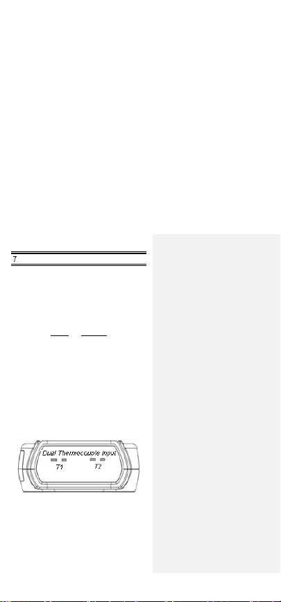
CONNECTING A THERMOCOUPLE
Use the correct thermocouple type for
your instrument setting. Using an
incorrect thermocouple type will result in
erroneous readings. Thermocouples are
colour coded by type using the North
American ANSI Color Code as follows:
TYPE COLOR
J Black
K Yello
w
T Blue
E Purple
Thermocouple connectors have one
wide blade and one narrow blade. Do
not force connector in backwards.
Connect thermocouples to receptacles
at top of instrument as shown in the
following illustration:
Page 12

- 10 -
Thermocouple wiring polarity must be
correct. If readings decrease as the
temperature increases, the thermocouple wires may be reversed. The red
wire is negative for thermocouple wires
manufactured in North America.
If no probe is connected the display
will read “open”.
Thermocouples are sensitive at the
tip or measuring junction. When
taking measurements, allow time for
the reading to stabilize. Multiplying
the time constant of the probe by 5
will give you the approximate time
required.
Page 13

- 11 -
KEY FUNCTIONS
Note: Function keys change in setup
mode to provide advanced operation
flexibility. Text above key will indicate
function.
F1
Step through Min, Max and
Avg readings.
F2
Choose probe T1, T2 or T1T2
F3
Toggle between menu and
measure mode
hold
Freeze display
on/off
light
Turns meter on and off
(press and hold for 3
seconds to turn off)
Press momentarily to turn on
backlight
recall▲
Recalls and steps through
stored readings
log▼
Stores current measured
value to memory
Page 14

- 12 -
DISPLAY OVERVIEW
The dot matrix display features a large
primary display, smaller secondary
displays for channel info or Min/Max/
Avg readings, and helpful annunciators
for added measurement data.
1
HOLD - Active
2
Data logging is Active
3
Alarm enabled – channel in alarm
indicated: T1 or T2 or T1&T2
4
MAX/MIN/AVG of Secondary
channel if MIN/MAX/AVG activated
5
MAX/MIN/AVG of Primary channel
if MIN/MAX/AVG activated
6
Min/Max hit time since Min/Max
activated. For Avg, it is continually
increments since activated
7
Current active Mode –
Min/Max/Avg
1 2 3 4 7 6 5
Page 15

- 13 -
MEASUREMENT MODE
On initial start-up, the meter will display
the measured value for input one in the
primary display and for input two in the
secondary display.
Pressing the F2 key will toggle primary
display through input one (T1), input
two (T2), and the delta (T1 – T2) values.
Pressing the F1 key initiates and
toggles through Minimum, Maximum,
and Average reading modes.
Pressing F3 enter accesses Setup
mode.
Page 16
- 14 -
HOLD FUNCTON
Press the hold key to retain the reading
on the display. Press the hold key again
for normal operation.
MIN, MAX, and AVG FUNCTION
Press the F1 key to toggle between
the minimum, maximum, and average
readings. This function is ideal for
monitoring unattended operations while
continually displaying every temperature
change that occurs. The minimum,
maximum, and average values are
sensed and automatically stored.
To exit and clear this function, press
the F3 key to access the Menu
functions. See the Clear Reset menu
section for more details.
DATA LOGGING
Press the log ▼ key to store the current
reading to memory. The memory
indicator M = 1234 shows the memory
location for the next stored reading.
Press the recall ▲ key to review stored
readings.
See section on Data Logging for timed
logging, and logging to a computer
(model 91428-04 only).
See section on Clear/Reset for
information on clearing stored readings.
Page 17
- 15 -
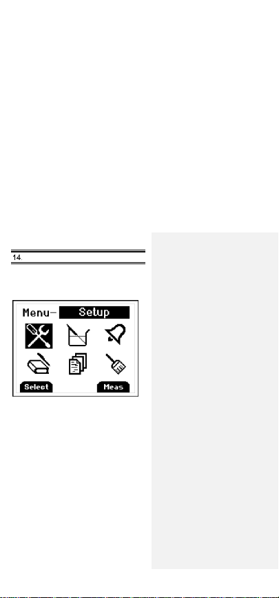
SETUP MODE
To access the setup mode from
measurement mode, press the F3 key
(Menu).
Press ▲▼ keys o n the meter key pad
to scroll through options.
To enter a setup screen, press
Select F1 key.
To return to measurement mode press
Meas F3 key. Following menu options
are listed:
1. General setup
2. User field calibration
3. Alarm settings
4. Data logging settings
5. View user calibration report
6. Clear/reset options
Page 18
- 16 -
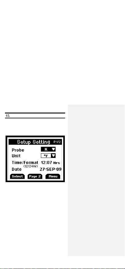
GENERAL SETUP SCREEN
The first page of the General Setup
screen lets you set probe type,
measurement units, time, and date.
Press F1 to indicate you want to change
the setting of the current parameter or
recall▲ or log▼ to move to the next
parameter.
Press recall▲ or log▼ to change the
options.
Press F2 to choose the next setting.
Whenever set the options, press F1
for accepting the choice.
Page 19
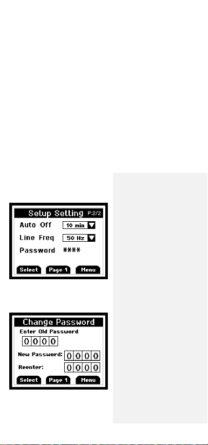
- 17 -
On the second page, you can set auto-off
time, line frequency, and password.
This screen below is used to reset/change
password. In the event if uses forget
his/her password, 5586 can be used to
reset to a new value
Page 20
- 18 -
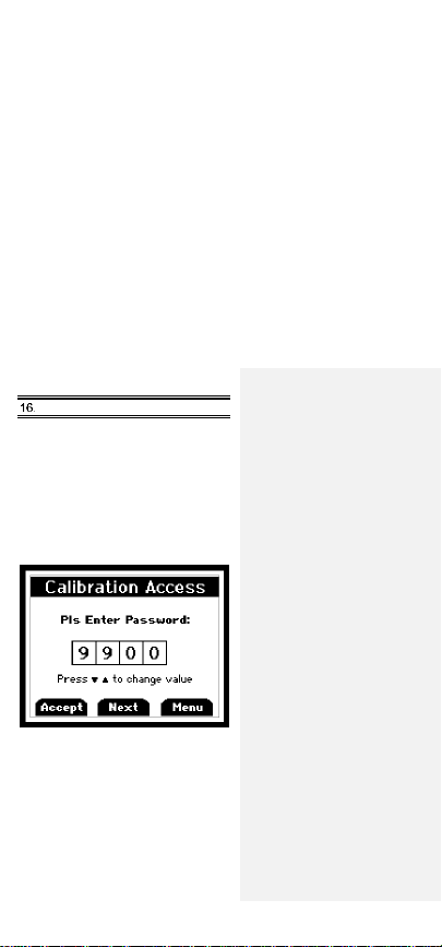
CALIBRATION SCREEN
The thermometer is factory calibrated and
does not require calibration before use.
The Calibration function allows singlepoint calibration of the meter at 0°C (32°F)
to compensate for thermocouple offset
error. It is NOT necessary to perform a
field calibration to obtain specified meter
accuracy. Use the field calibration feature
to improve thermometer/probe accuracy or
to compensate for thermocouple drift
.
Before you go into the calibration mode,
you must enter the password. Press F2
to change to the next digit. (Default
Password is 9900)
There are three calibration options:
Offset – adjusts at a single point
Slope – adjusts at two points
Match – adjusts readings on T1 to match
those on T2. Or adjusts T2 to match T1.
Page 21
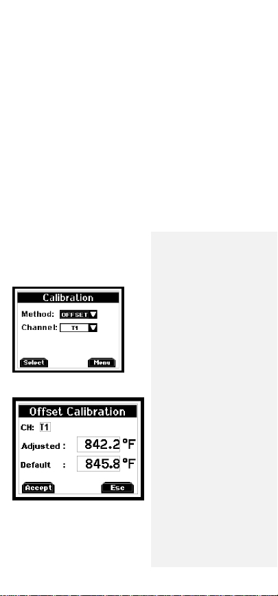
- 19 -
Select calibration method by pressing
F1 and the
▲ or ▼ keys.
Then select
the channel you with to calibrate the
▲ or ▼ keys
.
Offset Calibration
Use the ▲ or ▼ keys to adjust the value
to match known temperature standard.
Press F1 to accept.
Page 22
- 20 -
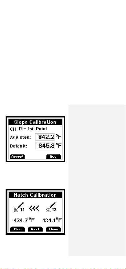
Slope Calibration
Use the ▲ or ▼ keys to adjust the value
to match known temperature standard.
Press F1 to accept. Then move to second
temperature point using the ▲ or ▼ keys
and repeat.
Match Calibration
Use the ▲ or ▼ keys to adjust the value
to match T1 readings and T2 readings.
Page 23
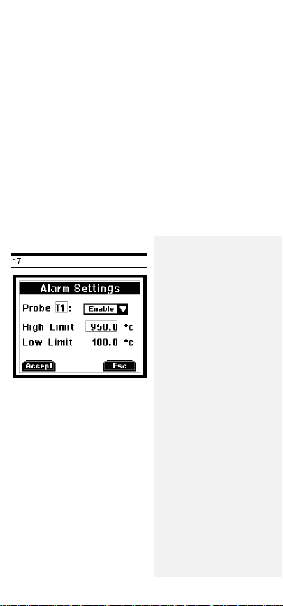
- 21 -
ALARMS SCREEN
Disable or enable the alarm for individual
probe by pressing recall▲ or log▼ and F1
to accept. Increase or decrease individual
limit by pressing recall▲ or log▼.
Page 24
- 22 -
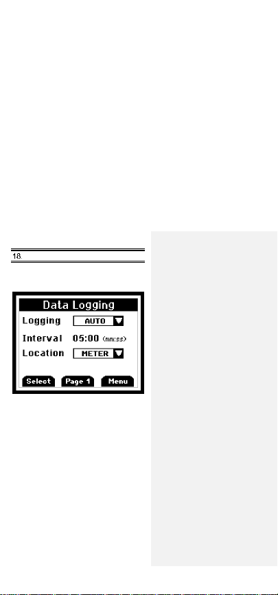
DATA LOGGING SCREEN
Data Transfer from Meter to Computer
(Model 91428-04 only)
Press recall▲ or log▼ to choose the
logging methods as auto or manual. If it
is auto logging, using recall▲ or log▼
to set time interval. Its range is from
0 min to 60 min.
Button “Page 1” will appear only in
model 91428-04.
Please refer to soft copy of the driver
manual in the CD for installation and
data logging instructions.
***NOTE: METER MUST BE TURNED
ON PRIOR TO CONNECTING USB
CABLE OR COMPUTER MAY NOT
RECOGNIZE THE INSTRUMENT.***
Page 25
- 23 -
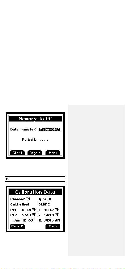
Once the USB connection is established,
press the Start button to download data
from Meter to PC using HyperTerminal.
CALIBRATION REPORT SCREEN
The Calibration report will show the time
and date along with results of the last
user calibration.
Page 26

- 24 -
CLEAR / RESET SCREEN
Press F1 to choose which data you want
to clear or reset. For calibration, logged
data, and reset all, you will have to enter
the password to proceed. (Default
Password is 9900)
Page 27

- 25 -
MAINTENANCE
Properly us
ed, the th
ermome
ter
should
maintain calibr
ation indefinitely
and
not
require service
other than
occasional
cleaning
of the
housing and changing
of
the batteries.
CLEANING
WARNING:
TO PREVENT IGNITION OF A
HAZARDOUS ATMOSPHERE BY
ELECTROSTATIC DISCHARGE,
CLEAN WITH DAMP CLOTH.
Do
not
clean wi
th
abrasives or solven
ts.
Use mild
detergents,
never immerse nor
use excessive
fluid.
BATTERIES
If there is no display when the meter is
turned on, check condition of the three AA
batteries. Also check that the battery
terminals are clean and batteries are
properly installed. If replacement is
necessary, refer to the BATTERY
INSTALLATION AND REPLACEMENT
section for replacement procedure.
Page 28

- 26 -
TROUBLESHOOTING
The following chart lists the most probable
faults. There are no internal adjustments
or user-replaceable parts.
FAULT
ACTION
NO
Display
Check condition of batteries.
Check that batteries are inserted
properly.
Display
shows
- - - -
Out-of-range indication.
Display
shows
OPEN
No thermocouple connected in
the connector.
Display
shows
Err
If display shows this message
other than during the field
calibration mode, please return
the instrument for servicing.
Cannot
connect
to PC
(model
91248-04
only)
Ensure that the meter is powered
on and measuring prior to
connecting to USB port. Before
and after the driver is installed,
your PC may not recognize the
meter if it is not powered on prior
to connecting the USB to the
computer.
Page 29

- 27 -
ACCESSORIES
Replacem
ent
Meters and Meter
Accessories
Item
Number
Dual-input J/K/T/E thermocouple
thermometer
91428-03
Dual-input data logging thermocouple
thermometer
91428-04
Rubber armor with stand
35427-80
Hands-free kit (two magnets and
strap)
35427-85
USB cable (model 91428-04 only)
35427-86
General-purpose probe, type K
08516-55
Penetration probe, type K
08516-65
Surface probe, type K
08516-60
Clip-on probe, type K
08469-02
General-purpose probe, type J
08517-55
Penetration probe, type J
08517-65
Surface probe, type J
08517-60
Clip-on probe, type J
08469-00
Page 30

- 28 -
WARRANTY
The Manufacturer warrants this product to
be free from significant deviations from
published specifications for a period of
three years. If repair or adjustment is
necessary within the warranty period, the
problem will be corrected at no charge if
it is not due to misuse or abuse on your
part as determined by the Manufacturer.
Repair costs outside the warranty period,
or those resulting from product misuse or
abuse, may be invoiced to you.
PRODUCT RETURN
To limit charges and delays, contact the
seller or Manufacturer for authorization
and shipping instructions before returning
the product, either within or outside of the
warranty period. When returning the
product, please state the reason for the
return. For your protection, pack the
carefully and insure it against possible
damage or loss. The Manufacturer will
not be responsible for damage resulting
from careless or insufficient packing.
Page 31

- 29 -
INNOCAL® CALIBRATION AND
REPAIR SERVICES
Optimum performance of your
temperature-measuring instrument is
not a timeless condition. To ensure quality
measurements, have your instrument
calibrated regularly. Trust InnoCal® to
satisfy your calibration and equipment
repair needs. With over a decade of
service, we've helped thousands of
customers meet ISO, FDA, EPA,
GLPs/cGMPs and other quality standards.
Conformity*
ISO/IEC 17025:2005 accredited
NIST Handbook 150, 2000 Edition
ANSI/NCSL Z540-2-1997
NIST Technical Note 1297
ISO 9000:2000
Fast Service
Our substantial inventory of replacement
parts ensures a fast turnaround and
prevents costly downtime. Most
instruments serviced in 5 business days!
Excellent Value
Get quality at a fair price. Our InnoCal®
NIST-traceable certificates offer extensive
test data on a broad range of
measurement parameters without
breaking the bank!
Page 32

- 30 -
Reliable Support
Trust in our free diagnostic support and
troubleshooting advice. Our factorytrained metrologists and technicians
are armed with years of experience
and extensive technical data.
Convenient Reminders
It’s so easy to keep your instruments
functioning properly. Based on your
requirements, InnoCal will send you a
reminder when it’s time to recertify or
service your instrument.
We provide you with the documentation
you need to meet your most stringent
quality requirements for the control of
inspection, measuring, and test
equipment.
Certification includes certificate of
calibration with test data, including:
● Description and identification of the
item certified
● Condition of the item
● Issue date
● Identification of calibration procedure
● Calibration date
● As found/as left test data (where
applicable)
● Signature of technician
● Statement of estimated uncertainty
● List of equipment used to perform
calibration (including their calibration
dates)
Page 33

- 31 -
With today's high quality standards such
as ISO 9000, certification is becoming
increasingly important. Traceability is not
a timeless condition. It must be verified
and maintained over the life of the
calibration to ensure the highest accuracy
possible. When you have your calibration
done by InnoCal, we will send you an
automatic reminder when it is time to
recalibrate your instrument.
Are your calibration certificates
good enough?
InnoCal surpasses the competition by
providing the most complete certificates
as required by NIST. All of our certificates
include measured data and point-by-point
measurement uncertainty, and by request,
we’ll provide test accuracy and test
uncertainty ratios at no extra cost.
Call us today and see why InnoCal is
The Choice of Quality.
*See our Scope of Accreditation for any limitations.
Calibration against NIST-traceable
standards
Four test points across range of instrument.
Meters: –270 to 2316°C (–454 to 4200°F)
Probes & Systems: –80 to 1000°C (–112 to 1832°F)
**Actual range is dependent on type of probe
Meter only
Probe only
System
(meter + probe)**
17000-10
17001-10
17002-10
InnoCal—The Choice of Quality
866-INNOCAL (866-466-6225)
www.InnoCalSolutions.com
Page 34

- 32 -
TECHNICAL ASSISTANCE
If you have any questions about the
use of this product, please contact the
Manufacturer or authorized seller.
For more information, contact:
OAKTON
Instruments/Thermo Scientific
Products, please contact your nearest
distributor or
Cole-Parmer
Toll-Free: 1-800-323-4340
Phone: 1-847-549-7600
Fax: 1-847-247-2929
ColeParmer.com/Digi-Sense
1065DGMAN_91428-03,-04
Formatted: Font: 9 pt, Bold
Formatted: Left, Indent: Left: 0.08", Line spacing:
Exactly 12 pt
Formatted: Left, Indent: Left: 0.08", Line spacing:
Exactly 12 pt
 Loading...