

Page 1
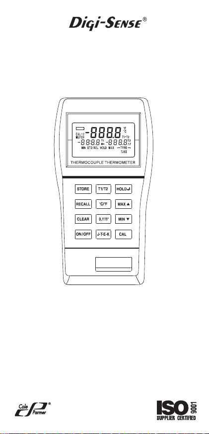
THERMOCOUPLE THERMOMETER
Dual J-T-E-K
®
MODEL
Cole-Parmer Instrument Co.
V ernon Hills, Illinois U.S.A. 60061-1844
e-mail: techinf o@coleparmer.com
68X309908 Rev. 0 08/03
NO. 91100-40
625 East Bunker Court
(847) 549-7600
(847) 247-2929 (Fax)
800-323-4340
www.coleparmer .com
A-1299-0632
Edition 07
Page 2

CERTIFICA TE OF
CONFORMANCE
This thermometer was calibrated using equipment traceable to the National Institute of Standards and Technology (NIST).
This instrument conforms to
NIST monograph 175 revised to
ITS-90.
The accuracy of the thermometer at the time
of calibration was within specifications stated
in the operating manual.
Model No.:__________________________
Serial Number:______________________
Date placed in service:________________
To purchase an NIST certificate of traceabil-
ity with test data and test date for meter and
probe please contact:
Cole-Parmer Instrument Company
625 East Bunker Court
Vernon Hills, Illinois, U.S.A. 60061-1844
Toll-free: 800-323-4340
Page 3
INTRODUCTION
This versatile hand-held instrument provides highly
accurate temperature measurements in Celsius, or
Fahrenheit, using a wide range of thermocouple
types. The temperature range for each type thermocouple is listed in the following chart.
TYPE °C °F
J –200 to 1000 –328 to 1832
K –250 to 1372 –418 to 2501
T –250 to 400 –418 to 752
E –250 to 1000 –418 to 1832
1
Page 4

The instrument is designed for easy operation and
includes the following f eatures:
•Operator selection of temperature scale
•Resolution of 0.1° from −150°C to 999.9°C
(−238°F to 999.9°F)
•LCD with three four-digit displays
• T wo (2-blade f emale) ANSI mini-connector inputs
•Hold feature for temporarily retaining a reading
•T wo-point field calibr ation capability
•Low battery warning
•Stores up to 25 readings
•Scrolls through all stored readings
•Displays MIN and MAX readings
•Scrolls between T1, T2, and T1-T2 readings
•Built-in tilt stand for easy hands-free operation
2
Page 5
SAFETY PRECAUTIONS
WARNING
LOW LEVEL SIGNALS SUPPLIED BY STANDARD THERMOCOUPLES. UNDER NO CIRCUMSTANCES SHOULD THE INPUT VOL TA GE
EXCEED THE SPECIFIED 50V RMS.
CAUTION
MICROWAVE OVENS OR ANY ABNORMALLY
HOT OR COLD AREAS.
CAUTION
STRUMENT. DEAD BA TTERIES CAN LEAK AND
CAUSE D AMA G E TO UNIT.
DANGER
MA Y ALSO BE PRESENT AT THE BA TTER Y TERMINALS. AL WAYS DISCONNECT THE THERMOCOUPLE WHEN CHANGING BATTERIES.
WARNING
PHERE, BA TTERIES MUST ONLY BE CHANGED
IN AN AREA KNOWN TO BE NON-HAZARDOUS .
AVERTISSEMENT
D’ATMOSPHERES DANGEREUSES, NE
CHANGER LES BATTERIES QUE DANS DES
EMPLACEMENTS DESIGNES NON DANGEREUX.
WARNING
PHERE BY ELECTROSTATIC DISCHARGE,
CLEAN WITH DAMP CLOTH.
THIS INSTRUMENT IS
DESIGNED TO ACCEPT
DO NOT USE OR STORE
THIS INSTRUMENT IN
WEAK BA TTERIES SHOULD
NOT BE LEFT IN THE IN-
VOLTAGES PRESENT AT
THE THERMOCOUPLES
TO PREVENT IGNITION OF
A HAZARDOUS ATMOS-
AFIN DE PREVENIR
L’ INFLAMMATION
TO PREVENT IGNITION OF
A HAZARDOUS ATMOS-
3
Page 6

SPECIFICATIONS
THERMOCOUPLE PROBES
Ty pe Temperature Range
Type J: –200°C to 1000°C (–328°F to 1832°F )
Type K: –250°C to 1372°C (–418°F to 2501°F )
T ype T: –250°C to 400°C (–418°F to 752°F )
Type E: –250°C to 1000°C (–418°F to 1832°F )
Accuracy > –150°C: ±0.1% of reading, ±0.4°C
(±0.7°F)
Accuracy < –150°C: ±0.25% of reading, ±1°C
(±2°F)
Linearization: Conforms to NIST monograph 175
revised to ITS-90.
Input Protection: 50V rms
Conversion Rate: Reading 0.6 seconds per
update.
Connector: Two-blade f emale ANSI mini-connector
inputs.
Battery
Size: Two AA, 1.5V alkaline ANSI-L40,
IEC-LR6
Life: 750 hours continuous, typical
Display: LCD with 0.4 in high characters main
readout and 0.2 in high characters secondary
displays, 4 digits each displa y plus various annunciators.
4
Page 7

Temperature/Humidity Range
Operating:
Stated Accuracy: 18°C to 28°C
Useful Range: 0°C to 40°C
Storage: −40°C to 65°C
Humidity: 10% to 90%
Dimensions
3 cm D x 8.4 cm W x 15.8 cm H
(1.2 in x 3.3 in x 6.2 in)
Weight with batteries: 227 grams (8 ounces)
Ingress protection: Meets IEC-529 IP-54 for dust
and water-resistant enclosures.
Intrinsic safety
This product is energy limited for intrinsically safe
operation in hydrogen atmospheres per Class I,
Division 1, Groups A, B, C, and D hazardous
(classified) locations for UL per UL913 and CSA
per C22.2 No. 0-M1982 and No. 157-M1987.
Maximum surface temperature: 135°C (T4); UL
file No. E182612 (1997).
Compliance (For CE Mark)
EN61326-1/A1: 1998 (EU EMC Directiv e)
(64°F to 82°F)
(32°F to 104°F)
(−40°F to 149°F)
(non-condensing)
5
Page 8

BATTERY INSTALLATION AND
REPLACEMENT
CAUTION
INSTRUMENT. DEAD BATTERIES CAN LEAK
AND CAUSE DAMAGE T O UNIT.
DANGER
MA Y ALSO BE PRESENT AT THE BA TTER Y TERMINALS. AL WAYS DISCONNECT THE THERMOCOUPLE WHEN CHANGING BATTERIES.
WARNING
PHERE, BA TTERIES MUST ONLY BE CHANGED
IN AN AREA KNOWN TO BE NON-HAZARDOUS .
AVERTISSEMENT
D’ATMOSPHERES DANGEREUSES, NE
CHANGER LES BATTERIES QUE DANS DES
EMPLACEMENTS DESIGNES NON DANGEREUX.
WEAK BA TTERIES SHOULD
NOT BE LEFT IN THE
VOLTAGES PRESENT AT
THE THERMOCOUPLES
TO PREVENT IGNITION OF
A HAZARDOUS ATMOS-
AFIN DE PREVENIR
L’ INFLAMMATION
6
Page 9
If battery indicator turns on, battery life is approximately 8 to 10 hours. The battery indicator will start
blinking with less than 1 hour of life remaining.
A T THIS POINT BATTER Y MUST BE CHANGED .
IF BATTERY VOLTAGE GOES TOO LOW, DISPLA Y WILL GO BLANK.
See SPECIFICA TIONS f or battery type.
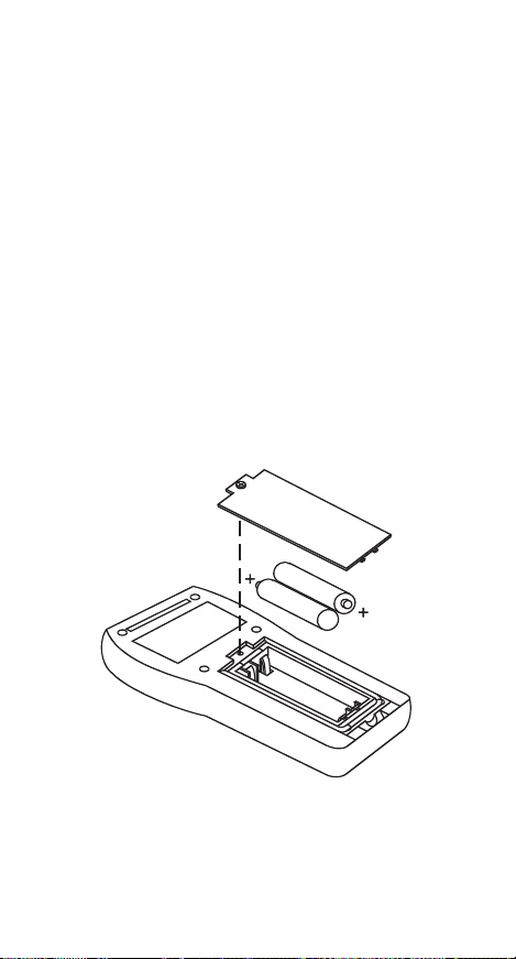
1. Before changing battery , turn instrument off and
disconnect thermocouple(s).
2. Loosen screw and lift battery cover off back of
case.
3. Remove the two AA batteries.
4. Insert two new batteries observing polarity .
5. Install cover and tighten screw.
7
Page 10
CONNECTING A THERMOCOUPLE
Note: Be sure your instrument setting (J, T, E or K)
matches the thermocouple you are using.
Use the correct thermocouple type for your instru-
ment. Using an incorrect thermocouple type will
result in erroneous readings. Thermocouples are
color coded by type using the North American ANSI
color code as follows:
TYPE COLOR
J Black
K Yellow
T Blue
E Purple
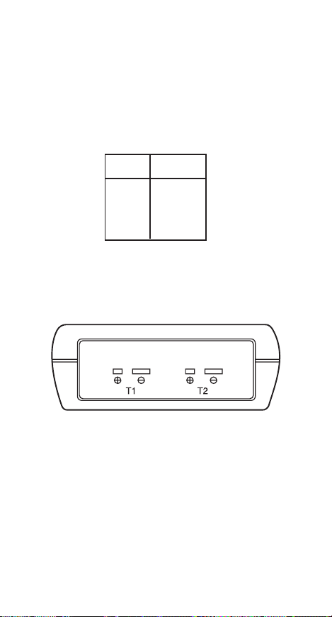
Thermocouple connectors have one wide blade and
one narrow blade.
wards.
Connect thermocouple(s) to receptacle at
top of instrument.
Do not force connector in back-
If only one thermocouple is being used, it can be
connected to either T1 or T2. The thermometer will
automatically determine which connector is being
used. When two thermocouples are used, connect
one to the T1 connector and one to the T2
connector.
Thermocouple wiring polarity must be correct. If
readings decrease as the temperature increases,
the thermocouple wires may be reversed. The red
wire is negative for thermocouple wires manufactured in North America.
8
Page 11
91011
Page 12

Page 13

Page 14

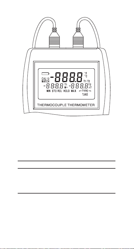
QUICK SETUP
Note: Review warnings on page 6.
1. Install batteries.
2. Connect thermocouple(s).
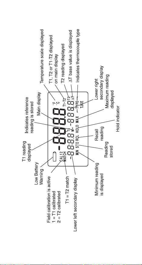
3. Press the ON/OFF key. The thermometer performs a self-test and all display digits and indicators, as shown below, should remain on for
approximately one second.
4. Use J-T-E-K key to select the correct thermo-
couple and the °C/°F key to select the desired
scale.
If a thermocouple has not yet been connected to
one or more inputs on the instrument, you will see
this display:
This message also appears if a thermocouple is
broken. No measurements can be made while this
warning is displayed.
12
Page 15

COMPLETE SETUP PROCEDURE
The setup procedure is used to select the temperature scale, resolution, and thermocouple type.
NOTE
Selected settings are stored in memory and will
remain in memory even after power is turned off,
or while batteries are being replaced.
SELECTING TEMPERA TURE SCALE
Select °C or °F by pressing the °C/ °F ke y. Each
time the key is pressed the temperature scale will
switch. Switching between °C and °F can be done
at any time during operation.
Each time you turn the instrument on, it will power
up with the same settings that were set when the
unit was last turned off.
SELECTING RESOLUTION
Select 0.1° or 1° resolution by pressing the
0.1°/1° key . This ke y toggles between the two resolutions. When measuring temperature above 999.9°
or below −150°C the thermometer automatically
autoranges to 1° resolution.
SELECTING THERMOCOUPLE TYPE
Select the thermocouple type, either J, T, E, K, by
pressing the J-T-E-K key. Each push of the key
will step to the next type thermocouple. The selected thermocouple type is indicated by the annunciators in the lower right corner of the display.
Continue with the OPERATING PROCEDURES
section or turn the instrument OFF by pressing the
ON/OFF key again. The displa y will b lank.
13
Page 16

OPERATING PROCEDURES
The unit will always power up with the upper display showing T1 unless T1 is not connected. If
only T2 is connected at power up, the upper display shows T2 and the lo wer left display indicates
T1 is open. If thermocouples are not connected to
T1 or T2 at pow er up, the upper display indicates
an open T1 and the lo wer right display indicates an
open T2.
If you are in single probe mode and the probe is
moved to the other connector or to restore the dual
probe mode, turn power OFF then back ON.
For optimum operation, allow about one min ute for
ambient temperature stabilization. If the unit has
been stored at an extreme ambient condition, more
time may be needed.
BASIC TEMPERATURE MEASUREMENTS
Check that the thermometer is turned on, the
probe(s) connected, the desired resolution 0.1° or
1° is selected, and the desired scale °C or °F, i s
selected.
Single Probe Measurements
The thermometer will automatically determine if T1
or T2 connection is being used.
Initially the upper display will indicate the measured
temperature and the annunciator will indicate which
probe is making the measurement. One of the lo wer
displays will indicate open and the annunciator will
indicate which probe is open. Pressing the T1/T2
key will cause the thermometer to go into the single
probe differential mode described later .
T emperatures > 999.9° ha ve a resolution of 1° and
therefore no decimal will be present.
14
Page 17

Dual Probe Measurements
The thermometer will automatically determine if one
or two thermocouples are connected. When two
thermocouples are connected, the upper main display will initially show T1 and the lower right display will show T2. Pressing the T1/T2 ke y once will
cause the upper display to show T2 and the low er
left display to show T1. Pressing the
T1/T2 key again will cause the upper display to
show T1-T2, the lo wer left display to show T1, and
the lower right display to show T2.
MAXIMUM READINGS
The maximum reading function displays the maximum reading since power up or since the last time
the clear function was used. The maximum reading function is ideal for monitoring unattended operations while continually displaying e very temperature change that occurs. The maximum and minimum values are sensed and automatically stored
until you are ready to observe the reading.
Do not turn the instrument OFF when a maximum
or minimum temperature value may be needed;
MAX/MIN memory contents will be lost. Factory
Calibration will be maintained.
15
Page 18

Single Probe Measurements
The displayed inf ormation depends on whether you
are using a single probe in the dual probe mode or
have changed to the single probe diff erential mode
by pressing the T1/T2 key .
If you are using a single probe and in the dual probe
mode, momentarily press the MAX
MAX annunciator turns on. If the probe is connected
to T1 the maximum reading will be shown in the
lower left display. If the probe is connected to T2
the maximum reading will be shown in the lower
right display. If a higher maximum occurs while in
the MAX mode, the higher reading will be display ed.
To turn off the maximum reading, press the MAX
▲▲
▲ ke y again.
▲▲
If you are in the single probe differential mode,
momentarily press the MAX
MIN annunciators turn on and both the maximum
and minimum readings appear in the lower displays.
The minimum will be on the left display and the
maximum on the right display . If a higher maximum
or lower minimum occurs while in the MAX mode,
the higher reading will be displayed. To turn off the
maximum reading, press the MAX
▲▲
▲ key. The
▲▲
▲▲
▲ k ey. The MAX and
▲▲
▲▲
▲ ke y again.
▲▲
16
Page 19

Dual Probe Measurements
Momentarily press the MAX
nunciator turns on, and both maximum T1 and T2
readings appear in the lower display. The T1 reading is on the left display and the T2 reading is on
the right display . Press MAX
Clearing a Maximum Reading
Press the CLEAR key then the MAX
maximum memory will be cleared.
MINIMUM READINGS
The minimum reading function displays the minimum reading since power up or since the last time
the clear function was used. While continually displaying ev ery temperature change that occurs, the
maximum and minimum values are sensed and
automatically stored until you are ready to observe
the reading.
Do not turn the instrument OFF when a maximum
or minimum temperature value may be needed;
MAX/MIN memory contents will be lost.
▲▲
▲ k ey. The MAX an-
▲▲
▲▲
▲ key again to cancel.
▲▲
▲▲
▲ key. The
▲▲
17
Page 20

Single Probe Measurements
The displayed inf ormation depends on whether you
are using a single probe in the dual probe mode or
have changed to the single probe diff erential mode
by pressing the T1/T2 key .
If you are using a single probe and in the dual probe
mode, momentarily press the MIN
annunciator turns on. If the probe is connected to
T1 the minimum reading will be shown in the lower
left display . If the probe is connected to T2 the minimum reading will be shown in the lower right display. If a lower minimum occurs while in the MIN
mode, the lower reading will be displa yed. To turn
off the minimum reading, press the MIN
again.
If you are in the single probe differential mode,
momentarily press the MIN
MIN annunciator turns on and both the maximum
and minimum readings appear in the lower displays .
The minimum will be on the left display and the
maximum on the right display . If a lower minimum
or higher maximum occurs while in the MIN mode,
the new readings will be displayed. T o turn off the
minimum reading, press the MIN
Dual Probe Measurements
Momentarily press the MIN
nunciator turns on, and both minimum T1 and T2
readings appear in the lower display. The T1 reading is on the left display and the T2 reading is on
the right display. Press the MIN
cancel.
▼▼
▼ k ey . The MIN
▼▼
▼▼
▼ key
▼▼
▼▼
▼ key. The MAX and
▼▼
▼▼
▼ k ey again.
▼▼
▼▼
▼ key. The MIN an-
▼▼
▼▼
▼ key again to
▼▼
Clearing a Minimum Reading
Press the CLEAR key then press the MIN
The minimum memory will be cleared.
18
▼▼
▼ key.
▼▼
Page 21

DIFFERENTIAL READINGS (T1-T2)
The differential function is used to compare two
different measurements and display the diff erence
between them. Differential measurements can be
made using either one probe or two probes.
Single Probe Measurements
For single probe measurements, one measurement
is stored as the reference measurement, then each
following measurement is compared to the reference. The reference measurement is viewed on
the lower left display, the differential v alue is shown
in the lower right display and the main display sho ws
the present T1 or T2 reading.
1. Place probe at first measurement point.
2. Press the T1/T2 key to store this ref erence temperature. The ∆T and M= annunciators will be
on and the reference temperature will be displayed on the lower left display. The ∆T indicates that the differential mode is selected and
the M= indicates that a reference temperature
has been stored. An y time after this that the T1/
T2 key is pressed, the M= v alue will be updated
to the present value shown in the main displa y .
3. Place the probe at the second measurement
point. The main display will immediately show
the new measured temperature and the lower
right display will immediately show the diff erence
between the reference temperature and the
present temperature point.
19
Page 22

Dual Probe Measurement
1. Connect the two probes to the two points of
measurement. The lower left displa y will indicate
the T1 temperature, the lower right display will
indicate the T2 temperature.
2. The main display can be scrolled between displaying T1, T2 or the diff erential temperature T1T2 by repeatedly pressing the T1/T2 ke y . To display the differential temperature press the T1/T2
key until the T1-T2 annunciator to the right of
the main display is on.
HOLD FUNCTION
Press the HOLD key to retain the reading on
the display. Press HOLD key again for normal
operation.
Maximum/Minimum Hold Readings
Press the MAX
key. To turn off the HOLD function and return to
normal operation, press the HOLD key again.
T o clear the maximum readings , press the CLEAR
key, then the MAX
Minimum/Hold
Press the MIN
T o turn off the HOLD function and return to normal
operation press the HOLD key again.
T o clear the minimum readings , press the CLEAR
key, then the MIN
▲▲
▲ key, then press the HOLD
▲▲
▲▲
▲ key .
▲▲
▼▼
▼ key , then press the HOLD key.
▼▼
▼▼
▼ key.
▼▼
STORED READINGS
The store function allows you to store up to 25 readings. Both T1 and T2 readings are stored. To store
readings proceed as follows:
20
Page 23

1. Momentarily press the STORE key. Both T1 and
T2 are stored. The upper main display will momentarily show the storage location number and
the STO annunciator will be on.
After three seconds the storage number will be replaced with the temperature reading but the ST O
annunciator remains on to indicate a temperature
reading has been stored. The STORE key may be
pressed as fast as once per second.
2. Repeat step 1 for all the points to be recorded
up to a maximum of 25. Each time the STORE
key is pressed the new reading will be stored
and the upper main display will show the storage location number for about 3 seconds. After
25 stored readings, the next time the STORE
key is pressed the main display will indicate
FULL.
RECALL READINGS
This function allows the stored readings to be recalled. RECALL shows each stored reading individually . To recall readings proceed as follows:
1. Momentarily press the RECALL key, the first
stored reading will be displayed on the low er display and the store number “1” will be displayed
on the upper display. The STO, and RCL annunciators will be on.
2. To step through the readings, press the
▼▼
MIN
▼ key or the MAX
▼▼
the key will advance to the next reading in sequence.
3. To return to normal operation press any other
key except ON/OFF, MAX
CALL.
▲▲
▲ key. Each press of
▲▲
▲▲
▲, MIN
▲▲
▼▼
▼ or RE-
▼▼
Clearing Stored Readings
Press the CLEAR key, then the STORE key. The
stored readings in memory will be cleared.
21
Page 24

CALIBRATION
The calibration function allows both single point and
dual point calibration of the thermometer. Single
point calibrates the offset only . Dual point calibrates
the offset first then calibrates the slope. The thermometer can be calibrated at any temperature.
When two probes are used, a match calibration
matches the T1 and T2 offsets.
It is not necessary to perform a field calibration to
obtain specified accuracies. Use the calibration
feature to improv e thermometer/probe accuracy or
to compensate for thermocouple probe calibration
drift.
The thermometer has a memory retention capability to hold calibration values even while power is
off or the battery is removed.
When you restart, there is no need to recalibrate.
Each of the four thermocouple types may be individually calibrated and stored.
NOTE
The temperature at which water boils (100°C/
212°F) is at sea level and standard atmospheric
pressure using distilled water. Changes in altitude
and barometric pressure will cause the boiling temperature to change.
As a general rule, the boiling temperature of water
will decrease 1°C (1.8°F) for e very 1000 feet above
sea level. F or example, at an ele vation of 5300 f eet
(1600 meters), water will boil at approximately
94.7°C (202.5°F).
Other liquids may also be used as calibration standards. Consult a chemical handbook for their freezing (melting) point and boiling point properties.
22
Page 25

When calibrating at freezing (0°C or 32°F) it is recommended to use crushed ice made of distilled
water in a dewar flask. Add crushed ice to top of
flask. Top off flask with distilled water . Continue to
add crushed ice to maintain tightly packed crushed
ice/water in flask.
CALIBRA TION PROCEDURES
Calibration Procedure (One Probe Detected)
This calibration function provides for both an offset
and slope field calibration of either T1 or T2. If only
one probe is detected, the procedure applies to that
probe, and the main display will indicate T1 or T2
as applicable. F or proper calibration the follo wing
conditions must be observed:
•The slope point must be a higher temperature than
the offset point.
•The difference must be at least 20°C.
•Use two points based on the expected high and
low temperatures. Temperatures measured outside of these limits may no longer meet accuracy
specifications.
Proceed as follows to calibrate the probes .
1. Place the probe at the lower known reference
temperature.
2. Offset Calibration: Momentarily press the CAL
key to enter the calibration mode, the CAL annunciator will flash. The temperature is displa yed
on the main display and Lo is display ed on the
lower left display. “Lo” signifies that this is the
offset point.
23
Page 26

3. Allow the reading to stabilize. If the displayed
temperature is higher or lower than the reference
temperature, use the MAX
the displayed reading or the MIN
crease the displayed reading until the ref erence
temperature is displayed. The MIN
key must be pressed at least once. The CAL
annunciator should be blinking during this
procedure.
4. Press the HOLD key to lock the offset calibration in and advance to the slope calibration.
T o return to normal operation press any key e xcept CAL or HOLD .
5. Slope Calibration: Place the probe at the higher
reference temperature.
6. Allow the reading to stabilize. If the displayed
temperature is higher or lower than the reference
temperature, use the MAX
the displayed reading or the MIN
crease the displayed reading until the ref erence
temperature is displayed. The MIN
key must be pressed at least once. The CAL
annunciator should be blinking during this procedure.
7. Press the HOLD key to lock the calibration
in.
▲▲
▲ key to increase
▲▲
▼▼
▼ key to de-
▼▼
▼▼
▼ or MAX
▼▼
▲▲
▲ key to increase
▲▲
▼▼
▼ key to de-
▼▼
▼▼
▼ or MAX
▼▼
▲▲
▲
▲▲
▲▲
▲
▲▲
24
Page 27

Calibration Procedure
(Tw o Probes Detected)
This calibration function provides for both an offset
and slope field calibration of either or both T1 and
T2. F or proper calibration the f ollowing conditions
must be observed:
•The slope point must be a higher temperature than
the offset point.
•The difference must be at least 20°C.
•Use two points based on the expected high and
low temperatures. Temperatures measured outside of these limits may no longer meet accuracy
specifications.
Proceed as follows to calibrate the probes .
1. Place the probe at the lower known reference
temperature.
2. Offset Calibration: Momentarily press the CAL
key to enter the calibration mode, the CAL annunciator will flash. The temperature is displa yed
on the main display and Lo is display ed on the
lower left display. “Lo” signifies that this is the
offset point.
3. Allow the reading to stabilize. If the displayed
temperature is higher or lower than the reference
temperature, use the MAX
the displayed reading or the MIN
crease the displayed reading until the ref erence
temperature is display ed. The MIN
key must be pressed at least once. The CAL
annunciator should be blinking during this
procedure.
4. Press the HOLD key to lock the T1 calibr a-
tion in and advance to T2 offset calibration, or
press the CAL key to skip T1 calibration. In either
case you will now be in T2 offset calibration.
▲▲
▲ key to increase
▲▲
▼▼
▼ key to de-
▼▼
▼▼
▼ or MAX
▼▼
▲▲
▲
▲▲
25
Page 28

5. Allow the reading to stabiliz e. If the displayed
temperature is higher or lower than the reference temperature, use the MAX
crease the displayed reading or the
▼▼
MIN
▼ ke y to decrease the display ed reading
▼▼
until the reference temperature is displayed.
The MIN
at least once. The CAL annunciator should
remain blinking during this procedure.
6. Press the HOLD key to lock the T2 offset
calibration in, or press the CAL key to skip T2
offset calibration and proceed with T1 slope .
If T1 or T2 offset calibration is skipped, then the
slope calibration for that input will also be skipped.
7. Slope Calibration: Place the probe(s) at the
higher reference temperature.
8. The temperature is displa yed on the main display and "Hi" is display ed on the lower left display.
9. Allow the reading to stabiliz e. If the displayed
temperature is higher or lower than the reference temperature, use the MAX
increase the displayed reading or the
MIN
until the reference temperature is displayed.
The MIN
at least once. The CAL annunciator should
remain blinking during this procedure.
10. Press the HOLD key to lock the T1 slope
calibration in and advance to T2 slope calibration, or press the CAL key to skip T1 slope
calibration. In either case you will now be in T2
slope calibration.
▼▼
▼ or MAX
▼▼
▼▼
▼ ke y to decrease the display ed reading
▼▼
▼▼
▼ or MAX
▼▼
▲▲
▲ key must be pressed
▲▲
▲▲
▲ key must be pressed
▲▲
▲▲
▲ key to in-
▲▲
▲▲
▲ key to
▲▲
26
Page 29

11. Press the HOLD key to lock the T2 slope
calibration in, or press the CAL key to skip T2
slope calibration. In either case you will now
be in T1 = T2 offset calibration. To return to
normal operation press any key except CAL
key or HOLD key.
If either T1 or T2 offset or slope were modified, CAL
1 or 2 will be lit.
12. The MATCH annunciator should be blinking.
When both readings (T1 and T2) are stable,
press the HOLD key to lock the T1 = T2
offset calibration in. The MATCH annunciator
will remain lit.
13. This completes the two-point calibration.
14. To return to normal operation press any key
except ON/OFF ke y or the CAL key.
Matching T1 and T2 Procedure
This procedure requires both probes to be at the
same temperature.
1. Place both probes at the same temperature and
let stabilize.
2. Momentarily press the CAL key until the MA TCH
annunciator is blinking. When both readings (T1
and T2) are stable, press the HOLD key to
lock in the calibration.
Clearing an Individual Cal Point: Press CAL key
until the desired point is displayed, then press
CLEAR key.
Clearing all Cal Points: Press CLEAR key , then
CAL key. Unit reverts to factory calibration with no
offset or slope compensation.
27
Page 30

FIELD CALIBRA TION LOCKOUT
AND RE-ENABLE
The calibration lockout f eature , pre v ents an y field
calibration changes. The loc kout remains in eff ect
until a lockout re-enable has been perf ormed. Use
the following procedures to loc kout or re-enable the
field calibration operation.
Lockout Procedure
1. T urn the thermometer off.
2. Simultaneously press and hold the CAL and the
CLEAR keys down and momentarily press the
ON/OFF key. Continue to hold the CAL and
CLEAR keys f or at least 5 seconds.
Re-Enable Procedure
1. T urn the thermometer off.
2. Simultaneously press and hold the HOLD and
the CAL keys down and momentarily press the
ON/OFF k ey . Continue to hold the HOLD and
CAL ke ys until the display b lanks.
28
Page 31

MAINTENANCE AND
TROUBLESHOOTING
Properly used, the thermometer should maintain
calibration indefinitely and not require service other
than occasional cleaning of the housing and changing of the batteries.
WARNING
PHERE BY ELECTROSTATIC DISCHARGE,
CLEAN WITH DAMP CLOTH.
Do not clean with abrasives or solvents . Use mild
detergents, nev er immerse nor use excessiv e fluid.
BATTERIES
If there is no display when the thermometer is
turned on, check condition of the two AA batteries.
Also check that the battery terminals are clean and
batteries are properly installed. If replacement is
necessary, refer to the BATTER Y INSTALLATION
AND REPLACEMENT section for replacement
procedure.
All stored readings are retained until cleared, even
if the batteries are removed for long periods.
TO PREVENT IGNITION OF
A HAZARDOUS ATMOS-
29
Page 32

SERVICE
WARNING
INTRINSIC SAFETY .
AVERTISSEMENT
PROMETTRE LA SECURITE INTRINSEQUE.
There are no internal adjustments or user replaceable parts.
If “Err” followed by the numbers 1 through 9 is displayed (see e xample below) return unit for service.
Note that “Err” alone ma y be displa yed during improper field calibration.
Note: Serial number label is located inside battery
compartment.
SUBSTITUTION OF COMPONENTS MAY IMPAIR
LA SUBSTITUTION DE
COMPOSANTS PEUT COM-
30
Page 33

TROUBLESHOOTING
The following chart lists the most probable faults.
There are no internal adjustments or user-replaceable parts. If this does not solv e the problem, ref er
service to your dealer.
FAULT ACTION
No display when Check condition of
turned on. batteries.
Check that batteries are
inserted properly.
Display shows Out of range indication.
- - - Display shows Open thermocouple
OPEn connection.
Display shows If display ed at any time
Err other than during field
calibration, return
instrument for service.
If Err 1 through Err 9 remains on the display , return
instrument for service.
31
A-1925-34
Printed in Singapore
68X309908 08/03
Rev. 0
Page 34

EU Declaration of Conformity
Name of Apparatus:
®
J-T-E-K
Thermocouple Thermometer
DIGI-SENSE
® Dual
Model Number: 91100-40
Description of Apparatus: Electronic
Thermometer using a Thermocouple Probe
Barnant Company declares that the above
model is in conformity to the following
harmonized standards and directives:
Applicable Applicable Manufacturer’s
Directives Specifications Report Number
89/336/EEC EN61326-1/A1: 1998 TR9648
92/31/EEC
93/68/EEC
Manufacturer:
Cole-Parmer Instrument Company
28W092 Commercial Aven ue
Barrington, IL 60010-2392
USA
T el.: 847-381-7050
Manufacturer’ s Signature:
5 Oct., 2000
James W . Doll Date
Vice President, Engineering
32
Page 35

WARRANTY
The Manufacturer warrants this product to be free
from significant deviations from published specifications. If repair or adjustment is necessary within
the warranty period, the problem will be corrected
at no charge if it is not due to misuse or abuse on
your part as determined by the Manufacturer. Repair costs outside the warranty period, or those
resulting from product misuse or abuse, may be
invoiced to you.
This product comes with a 3-year warranty.
PRODUCT RETURN
To limit charges and delays, contact the seller or
Manufacturer f or authorization and shipping instructions before returning the product, either within or
outside of the warranty period. When returning the
product, please state the reason for the return. F or
your protection, pack the product carefully and insure it against possible damage or loss. Any damages resulting from improper packaging are your
responsibility.
TECHNICAL ASSISTANCE
If you have an y questions about the use of this product, contact the Manufacturer or authorized seller.
Trademarks bearing the ® symbol in this publication are registered in the U.S. and in other countries.
A-3477-55
Printed in Singapore
68X309908 08/03
Rev. 0
Page 36

ACCESSORY THERMOCOUPLE
PROBES
Cole-Parmer offers a wide variety of thermocouple
probes, wire, connectors, e xtension cables, switch
boxes , accessories, and calibration services.
The popular probes listed below have a nylon
handle, a 5-ft coiled cord and a 316 SS sheath.
General-purpose probes, 5 in long x 0.156 in dia
with 0.093 in dia tip. 3 second time constant.
Type J 08517-55
Type K 08516-55
Type T 08500-55
Penetration probes, 4 in long x 0.156 in dia sharp
tip. 5 second time constant.
Type J 08517-65
Type K 08516-65
Type T 08500-65
Surface probes, 10 in long with 5/8 in dia alumi-
num and ceramic tip. 6 second time constant.
Type J 08517-60
Type K 08516-60
Type T 08500-60
Air/gas probes, 8 in long sheath with 1/4 in dia
radiant heat shield. 45 second time constant.
Type J 08517-75
Type K 08516-75
Type T 08500-75
39800-98 Carrying case. Hard plastic case with
foam insert holds one meter and up to five probes.
Measures 21 in W x 12 in H x 3 in D.
91100-90 Soft Carrying case. Water-resistant
cloth.
 Loading...