


User Manual
Digi-Sense® TC9100 Advanced
PID and On/Off Temperature Controller
with Thermocouple Input
Models 89800-11 and 89800-12
THE STANDARD IN PRECISION MEASUREMENT
Find Quality Products Online at: sales@GlobalTestSupply.com
www.GlobalTestSupply.com

Table of Contents
Introduction ......................................................................................................... 3
Unpacking .......................................................................................................... 3
Controller Description—Front Panel .................................................................... 4
Controller Description—Back Panel ..................................................................... 5
Controller Description—Active Display Screen .................................................... 6
Setup and Operation .......................................................................................... 7
Initial Setup ................................................................................................ 7
Basic Operation Setup................................................................................ 7
Auto Tune Setup ......................................................................................... 7
PID Control Mode Setup (Default Mode) ........................................................ 8–15
ON/OFF Control Mode Setup ....................................................................... 16–22
Safety ................................................................................................................ 23
Specifications for Controller Models ................................................................. 24
Specifications for Sensor Input ......................................................................... 25
Screen Flow Charts ...................................................................................... 26–27
General Setup Flow Chart ....................................................................... 26
Advanced Menu Setup Flow Chart .......................................................... 27
Ferrite Clip Installation ....................................................................................... 28
Alternative Power Cords—for Various Countries ............................................... 29
Output Cord Adapters—for Various Countries ................................................... 30
Approvals .......................................................................................................... 31
Maintenance ...................................................................................................... 32
2
Find Quality Products Online at: sales@GlobalTestSupply.com
www.GlobalTestSupply.com

Introduction
The Digi-Sense TC9100 Advanced PID and On/Off Temperature Controller (Models 89800-11
and 89800-12) is designed to regulate a user-defined output device at a set point temperature.
The microprocessor control uses a PID algorithm that provides precise heating/cooling tolerances
for demanding applications in the laboratory or industrial setting.
The TC9100 is a microprocessor-based, digital indicating, single-loop temperature controller.
It has a single output located on the back of the controller. It features an auto-tuning function that
allows automatic configuration of the PID parameters with minimum user configuration required.
The TC9100 has a single thermocouple input that accepts J, K, N, R, S, T, B, and E sensors.
The controller automatically sets the PID parameters through a "learning" sequence in the
auto tune mode. PID parameters include proportional band, reset/integral, and rate/derivative.
The user-friendly LED display is to aid in monitoring and setup of the controller. The controller
automatically stores all user-defined information in nonvolatile memory.
Unpacking
Check individual parts against the list of items below. If anything is missing or damaged,
please contact your instrument supplier immediately.
1. Temperature controller
2. Grid support bracket (attached to the back of the controller)
3. 6-ft (3-m) detachable IEC power cord. Model 89800-11 comes standard with
a US 120 VAC plug; Model 89800-12 comes standard with a US 220 VAC plug.
See page 32 for additional cords.
4. Electrical noise canceling ferrite clip (connects to sensor input; see page 31 for reference)
5. User manual
6. Quick-start guide
3
Find Quality Products Online at: sales@GlobalTestSupply.com
www.GlobalTestSupply.com

Controller Description — Front Panel
7
6
2
1. RUN/STOP Button
Pressing RUN/STOP once will start the control process if the temperature Controller is stopped, or stop the control process if the
temperature controller is running. If the controller is running, “Heat” and “Cool” on-screen indicators will illuminate appropriately
in the “Alarm/Action Display”.
2. TUNE Button
Pressing TUNE once will start the AUTO TUNE cycle. AUTO TUNING must be enabled in the setup mode for this key to function.
(See page 14, Screen 16)
3. ALARM Button
In an ALARM situation, the screen will display either “WARNING” or “ERROR” with the corresponding message. A “WARNING”
will not stop the control process. An “ERROR” will stop the control process.
A. MANUAL RESET mode: Pressing ALARM once will silence the audible alarm and clear the on-screen alarm message. If the alarm situation
is still present, the “Alarm/Action Display” will remain illuminated. The alarm and on-screen message will not clear automatically, even if the
system is no longer in an alarm situation.
B. AUTO RESET mode: Pressing ALARM once will silence the audible alarm and clear the on-screen alarm message. If the alarm situation
is still present, the “Alarm/Action Display” will remain illuminated. If the system leaves an alarm situation, the system will automatically silence
the alarm and clear the on-screen alarm message.
1
5
4
3
4. SELECT Button
Pressing SELECT once will cycle through user-configurable control set points. All user-configurable set points will be underlined
with a greyed out line. The selected set point will be underlined. Change the set point with the UP and DOWN arrow buttons.
5. MENU Button
The MENU button provides access to all user-configurable setup parameters of the controller. Pressing this key once will scroll
through parameter options. Pressing and holding this key will exit to the home screen, saving any changes made up to that point.
6. UP, DOWN, BACK Buttons
The UP and DOWN arrow buttons will increase or decrease the value of the set point selected (underlined). Pressing the UP or
DOWN arrow keys will increase or decrease numerical entries by the least significant digit. The rate of acceleration will increase as
shown in the table below, starting from the least significant digit. Pressing and holding the UP or DOWN arrow key will increase or
decrease text entries without an acceleration factor. The Back button moves backwards through the General and Advanced Setup
Menus. To exit to the main screen from either menu, press and hold the MENU button.
Numbers… Increase/Decrease by…
0.0 – 0.9 0.1
0 – 9 1
7. HEAT, COOL, AND TUNE Indicators
When any of these modes are active they will have a block indicator on the display showing they are active. Example: When the
controller is in the heat mode and it is applying power to the heater output there will be an indicator block on the display to show
the heater output is active.
10 – 100 10
100 + 50
Table 1. Acceleration Factor Table
4
Find Quality Products Online at: sales@GlobalTestSupply.com
www.GlobalTestSupply.com

Controller Description — Back Panel
Heater/Cooler output based on model
5-15R ,115 VOLT
Model 89800-11
IEC 60320 C19, 230 VOLT
(Image shows this receptacle)
Model 89800-02
Model 89800-12
1. IEC power cord connection (see page 32 for additional cords)
2. Fuse
3. Heater/cooler output (see pages 33-34 for optional output cord adapters dependent on country)
4. Power switch
5. Grid support bracket
6. Thermocouple input (accepts type J, K, N, R, S, T, B, and E with mini-connector)
5
Find Quality Products Online at: sales@GlobalTestSupply.com
www.GlobalTestSupply.com
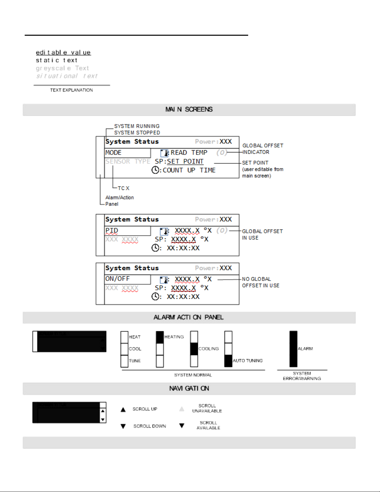
Controller Description — Active Display Screen
6
Find Quality Products Online at: sales@GlobalTestSupply.com
www.GlobalTestSupply.com

Setup and Operation
Initial Setup
Install controller in safe operating area.
Plug the heater or cooler (sold separately) into the output connector located on the back of the
controller.
Connect the thermocouple sensor to the thermocouple input connector located on the back of
the controller.
Place the ferrite clip over the lead wire of the thermocouple sensor. (See page 28 for reference
picture of installation of ferrite clip.)
Plug the supplied AC cord into the IEC power connector located on the back of the controller.
Basic Operation Setup
Turn power switch ON, located on the back of controller.
Follow the instructions on the “welcome” screen.
- Press SELECT key to read a brief description of each key on the front of controller.
- Press the MENU key to skip the instructions and enter the main operation screen.
Press the SELECT key to make a user-editable field active. A line will appear under the field
when the field is active for editing.
Use the UP/DOWN arrow keys to adjust the value that is active in a user-editable field.
Enter the user-configurable setup by pressing the MENU key from the system status screen.
Use the MENU key to advance through each menu setting.
Hold UP and press DOWN arrow keys to jump directly to Output Power adjustment screen.
Depending on process operation, follow the directions to set up the controller for the proper
operation of your process:
- PID (Factory default) on pages 8-15
- ON/OFF on pages 16-22
All changed settings will be retained in memory when returning to the System Status screen.
Use the flow charts (see pages 26-27) to have a visual of the controls menu layout.
Auto Tune Setup
Set up your process as noted in the initial setup.
Verify that the Auto Tune feature is enabled in the menu settings.
From the main operation screen, set the set point temperature.
Press the TUNE button and the indicators showing Heat and Tune will be illuminated on display.
The Set Point value can not be altered after the Tune process has started. The value is locked
until the Tune process is complete or aborted by the user.
Please note that the controller will tune at 90% of the set point. Don’t be alarmed if the controller
does not reach your entered set point in the tune mode.
Stopping the Tune operation prior to it finishing will cause the PID settings to be returned to
factory default values.
7
Find Quality Products Online at: sales@GlobalTestSupply.com
www.GlobalTestSupply.com

PID Control Mode Setup: (FACTORY DEFAULT MODE)
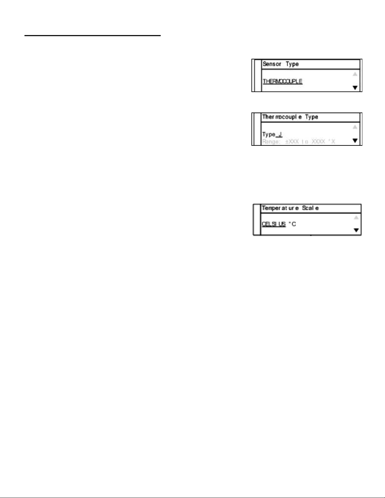
Screen # 1 - Selecting Sensor Type
The TC9100 is set to thermocouple.
Press MENU key to advance to next screen.
Screen # 2 - Selecting Thermocouple Type
Thermocouple is preselected on screen # 1.
Use the UP/DOWN arrow keys to select the desired
thermocouple type: J, K, N, R, S, T, B, or E.
Press MENU key to advance to screen # 3 after selection
has been made.
Screen # 3 - Selecting Temperature Scale
Use the UP/DOWN keys to select the desired temperature
scale: Celsius °C, Fahrenheit °F, Kelvin K, Reaumur °Ré,
or Rankine °Ra.
Press MENU key to advance to screen # 4 after selection
has been made.
8
Find Quality Products Online at: sales@GlobalTestSupply.com
www.GlobalTestSupply.com
PID Control Mode Setup:
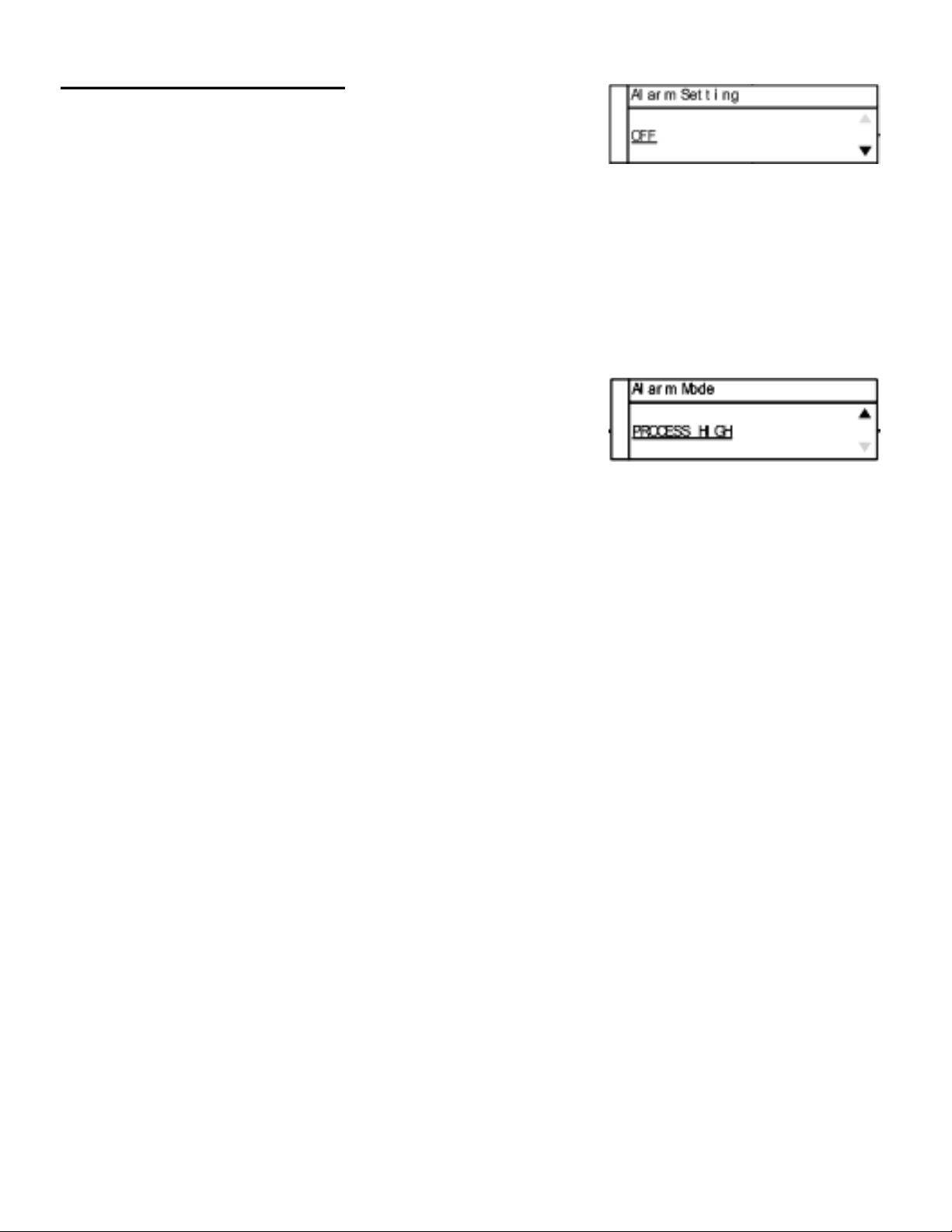
Screen # 4 - Selecting Alarm Setting
Use the UP/DOWN arrow keys to change between Auto Reset, Manual Reset, and Off.
Press MENU key to advance to next screen.
- If Auto or Manual is selected, the controller will advance to screen # 5.
- If selection is OFF, the controller will advance to screen # 9.
Screen # 5 - Selecting Alarm Mode
Use the UP/DOWN arrow keys to select alarm mode.
Selectable alarm modes:
- Process High: The alarm will be activated if the temperature rises above the
user set alarm value.
- Process Low: The alarm will be activated if the temperature goes below the
user set alarm value.
- Process High/Low: The alarm will be activated if the temperature goes above or
below the high and low temperature levels set by user.
Press the MENU key to advance to screen # 6 after selecting alarm mode.
9
Find Quality Products Online at: sales@GlobalTestSupply.com
www.GlobalTestSupply.com

PID Control Mode Setup:
Screen # 6 - Setting Alarm Mode Variables
This screen reflects the variable settings for the selected alarm mode from screen # 5.
-Set Point—Process High
- Press the UP/DOWN arrow keys to adjust the temperature val-
ue.
- When complete, press MENU key to advance to screen # 7.
- Set Point—Process Low
- Press the UP/DOWN arrow keys to adjust the temperature value.
- When complete, press MENU key to advance to screen # 7.
- Set Point—Process High/Low
- Press the UP/DOWN arrow keys to adjust the temperature value.
- Press the SELECT key to toggle between High and Low.
There will be a line below the active field.
- When complete, press MENU key to advance to screen # 7.
10
Find Quality Products Online at: sales@GlobalTestSupply.com
www.GlobalTestSupply.com

PID Control Mode Setup:
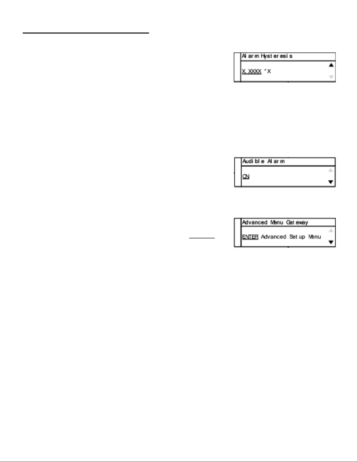
Screen # 7 - Setting Hysteresis Alarm
Use the UP/DOWN arrow keys to adjust value.
The user-defined value when the alarm will exit an
alarm condition. Example: User has a Process High alarm
programmed with a value of 150°C and has set the Alarm Hysteresis of 1°C. The alarm has
been activated after the temperature reached 160°C. When temperature reaches 149°C,
the alarm condition will not be active.
When complete, press MENU key to advance to screen # 8.
Screen # 8 - Setting Audible Alarm
Use UP/DOWN arrow keys to change value to either
ON audible alarm or OFF audible alarm.
When complete, press MENU key to advance to screen # 9.
Screen # 9 - Advanced Menu Gateway
Use the UP/DOWN arrow keys to change selection to ENTER.
When complete, press MENU key to advance to screen # 10.
The following screens are in the advanced portion of the
setup menu:
Screen # 10 - Calibration Gateway
Screen # 11 - Global Sensor Offset
Screen # 12 - Over Temperature Stop
Screen # 13 - Loop Break Stop
Screen # 14 - Control Action
Screen # 15 - Control Mode
Screen # 16 - Auto Tune
Screen # 17 - Proportional Gain Setup
Screen # 18 - Integral Gain Setup
Screen # 19 - Derivative Rate Gain Setup
Screen # 20 - Power Rate Control
Screen # 21 - Run Time
Screen # 22 - Power Failure Control
11
Find Quality Products Online at: sales@GlobalTestSupply.com
www.GlobalTestSupply.com
PID Control Mode Setup:
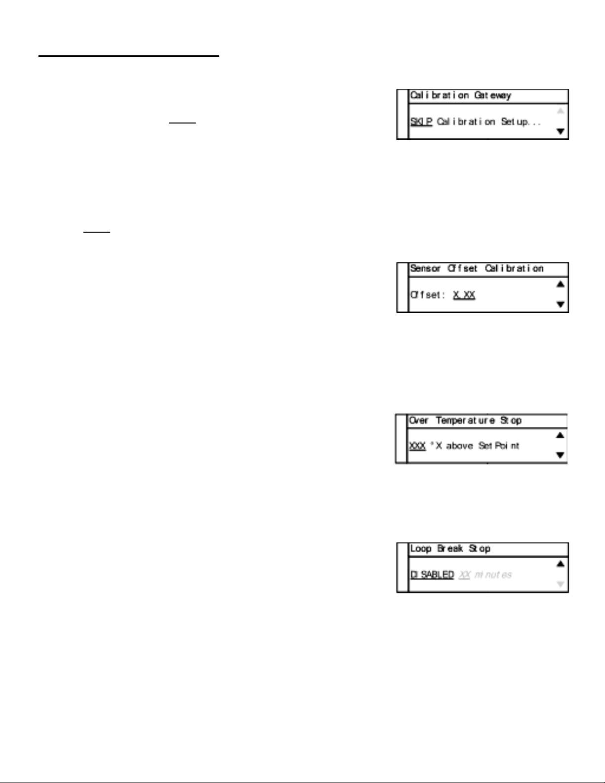
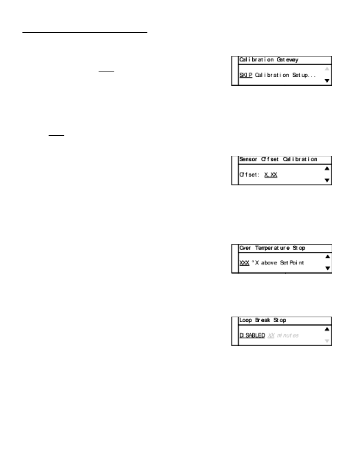
Screen # 10 - Calibration Gateway
Screen will default to SKIP Calibration Setup.
WARNING: Do not enter the calibration gateway unless
you have the proper calibration equipment to calibrate the sensor inputs associated with
this control. Changing calibration settings in the controller can cause errors in sensor
temperature readings and operation of the control. For instructions on how to use the
calibration functions, contact your instrument supplier.
With SKIP selected, press the MENU key to advance to screen # 11.
Screen # 11 - Global Sensor Offset Calibration
Use the UP/DOWN arrow keys to change the offset value.
The use of another temperature device is required to
determine the correct offset needed.
Adjusting this value is offsetting the sensor input temperature being displayed.
When complete, press MENU key to advance to screen # 12.
Screen # 12 - Over Temperature Stop
Use UP/DOWN arrow keys to change the value.
When sensor temperature goes above this value, the output
device will be turned off.
When complete, press MENU key to advance to screen # 13.
Screen # 13 - Loop Break Stop
Default value is ENABLED. Use UP/DOWN arrow keys to
change the value.
Loop Break Stop is a feature that will stop the process output
while the controller is in the run mode. If the controller senses there is no change in temperature
in a user set amount of time, the output will be turned off and error message will be displayed on
the screen along with an audible alarm.
Set to DISABLED if this function is not required.
When complete, press MENU key to advance to screen # 14.
12
Find Quality Products Online at: sales@GlobalTestSupply.com
www.GlobalTestSupply.com

PID Control Mode Setup:
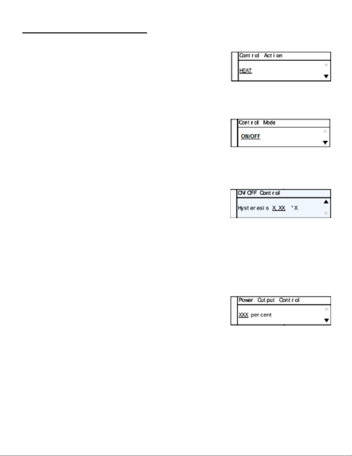
Screen # 14 - Control Action
Use UP/DOWN arrow keys to change the value.
Set for the process that is being performed: Heat or Cool
When complete, press MENU key to advance to screen # 15.
Screen # 15 - Control Mode
Use UP/DOWN arrow keys to change the value.
Default value is PID mode. (If different, select PID mode)
When complete, press MENU key to advance to screen # 16.
Screen # 16 - Auto Tune
Default value is ENABLED. Use UP/DOWN arrow keys
to toggle between ENABLED and DISABLED.
Select ENABLED to use the Tune key on the front panel to activate the Auto Tune function.
This function needs to remain ENABLED until the controller has been properly tuned to the
user’s particular application.
When complete, press MENU key to advance to screen # 17.
Screen # 17 - Proportional Gain Setup
Use UP/DOWN arrow keys to change the value.
WARNING: Do not change these values unless you have
experience in manual setup of PID (Proportional, Integral, and
Derivative) of this controller. These values are derived from running the auto tune function.
Altering the value after auto tune has been completed will affect the performance of the system.
When complete, press MENU key to advance to screen # 19.
13
Find Quality Products Online at: sales@GlobalTestSupply.com
www.GlobalTestSupply.com

PID Control Mode Setup:
Screen # 18 - Integral Gain Setup
Use UP/DOWN arrow keys to change the value.
WARNING: Do not change these values unless you have
experience in manual setup of PID (Proportional, Integral, and Derivative) of this controller.
These value are derived from running the auto tune function. Altering the values after
auto tune has been completed will affect the performance of the system.
When complete, press MENU key to advance to screen # 21.
Screen # 19 - Derivative Rate Gain Setup
Use UP / DOWN arrow keys to change the value.
WARNING: Do not change these values unless you have
experience in manual setup of PID (Proportional, Integral, and Derivative) of this controller.
These values are derived from running the auto tune function. Altering the value after
auto tune has been completed will affect the performance of the system.
When complete, press MENU key to advance to screen # 23.
14
Find Quality Products Online at: sales@GlobalTestSupply.com
www.GlobalTestSupply.com

PID Control Mode Setup:
Screen # 20 - Power Output Control
Use UP/DOWN arrow keys to change the value.
Default value is 100 percent.
This feature allows the user to reduce the output power to the output heating device—useful in
applications were temperature overshoot is occurring after auto tune has been completed.
Experimenting with this value will be necessary because every process setup is different.
When complete, press MENU key to advance to screen # 24.
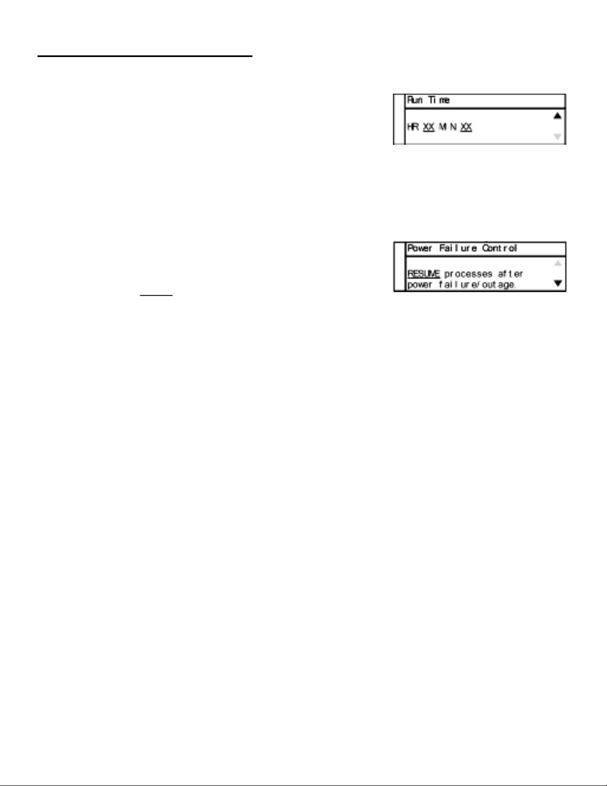
Screen # 21 - Run Time
Use UP/DOWN arrow keys to change the value.
Use SELECT key to toggle between the HR and MIN fields.
Run Time is a safety feature while the control is in the ON/OFF
or PID mode. The user can set a timer to have the output turned OFF if the time expires.
When complete, press MENU key to advance to screen # 25.
Screen # 22 - Power Failure Control
Use UP/DOWN arrow keys to change the value.
Default value is STOP:
STOP — If the controller loses power while in the run mode,
it will not resume the process once the power has been restored.
RESUME — If the controller loses power while in the run mode,
it will resume the operating process once the power has been restored.
When complete, press MENU key to advance to screen # 26.
Screen # 23 - Advanced Menu Exit
Setup is complete.
Automatically exit to the main operation screen.
15
Find Quality Products Online at: sales@GlobalTestSupply.com
www.GlobalTestSupply.com
ON/OFF Control Mode Setup:
Screen # 1 - Selecting Sensor Type
The TC9100 controller is set to thermocouple.
Press MENU key to advance to next screen.
Screen # 2 - Selecting Thermocouple Type
Thermocouple is preselected on screen # 1.
Use the UP/DOWN arrow keys to select the desired
thermocouple type: J, K, N, R, S, T, B, or E.
Press MENU key to advance to screen # 3 after
selection has been made.
Screen # 3 - Selecting Temperature Scale
Use the UP/DOWN keys to select the desired temperature
scale: Celsius °C, Fahrenheit °F, Kelvin K, Reaumur °Ré,
or Rankine °Ra.
Press MENU key to advance to screen # 4 after selection has been made.
16
Find Quality Products Online at: sales@GlobalTestSupply.com
www.GlobalTestSupply.com

ON/OFF Control Mode Setup:
Screen # 4 - Selecting Alarm Setting
Use the UP/DOWN arrow keys to toggle between
Auto Reset, Manual Reset, and Off.
Press MENU key to advance to next screen:
- If Auto or Manual is selected, the controller will advance to screen # 5.
- If OFF is selected, the controller will advance to screen # 9.
Screen # 5 - Selecting Alarm Mode
Use the UP/DOWN arrow keys to select alarm mode.
Selectable alarm modes:
- Process High: The alarm will be activated if the
temperature rises above the user set alarm value.
- Process Low: The alarm will be activated if the temperature
goes below the user set alarm value.
- Process High/Low: The alarm will be activated if the temperature
goes above or below the high and low temperature levels set by user.
Press the MENU key to advance to screen # 6 after selecting alarm mode.
17
Find Quality Products Online at: sales@GlobalTestSupply.com
www.GlobalTestSupply.com

ON/OFF Control Mode Setup:
Screen # 6 - Setting Alarm Mode Variables
This screen reflects the variable settings for the selected alarm mode from screen # 5.
-Set Point—Process High
- Use UP/DOWN arrow keys to adjust the temperature value.
- When complete, press MENU key to advance to screen # 7.
- Set Point—Process Low
- Use UP/DOWN arrow keys to adjust the temperature value.
- When complete, press MENU key to advance to screen # 7.
- Set Point—Process High/Low
- Use UP/DOWN arrow keys to adjust the temperature value.
- Press the SELECT key to toggle between High and Low.
There will be a line below the active field.
- When complete, press MENU key to advance to screen # 7.
18
Find Quality Products Online at: sales@GlobalTestSupply.com
www.GlobalTestSupply.com
ON/OFF Control Mode Setup:
Screen # 7 - Setting Hysteresis Alarm
Use the UP/DOWN arrow keys to adjust value.
The user-defined value when the alarm will exit an alarm
condition. Example: The user has a Process High alarm
programmed with a value of 150°C and has set the Alarm Hysteresis of 1°C.
The alarm has been activated after the temperature reached 160°C. When
temperature reaches 149°C, the alarm condition will not be active.
When complete, press MENU key to advance to screen # 8.
Screen # 8 - Setting Audible Alarm
Use UP/DOWN arrow keys to change value to either
ON audible alarm or OFF audible alarm.
When complete, press MENU key to advance to screen # 9.
Screen # 9 - Advanced Menu Gateway
Use UP/DOWN arrow keys to change selection to ENTER.
When complete, press MENU key to advance to screen # 10.
The following screens are in the advance portion of the setup menu:
Screen # 10 - Calibration Gateway
Screen # 11 - Global Sensor Offset
Screen # 12 - Over Temperature Stop
Screen # 13 - Loop Break Stop
Screen # 14 - Control Action
Screen # 15 - Control Mode
Screen # 16 - On/Off Control
Screen # 17 - Power Output Control
Screen # 18 - Run Time
Screen # 19 - Power Failure Control
19
Find Quality Products Online at: sales@GlobalTestSupply.com
www.GlobalTestSupply.com
ON/OFF Control Mode Setup:
Screen # 10 - Calibration Gateway
Screen will default to SKIP Calibration Setup.
WARNING: Do not enter the calibration gateway unless you
have the proper calibration equipment to calibrate the sensor
inputs associated with this controller. Changing calibration settings in the control can
cause errors in sensor temperature readings and operation of the control. For instructions
on how to use the calibration functions, contact your instrument supplier.
With SKIP selected, press the MENU key to advance to screen # 11.
Screen # 11 - Global Sensor Offset Calibration
Use the UP/DOWN arrow keys to change the offset value.
The use of another temperature device is required to
determine the correct offset needed.
Adjusting this value is offsetting the sensor input temperature being displayed.
When complete, press MENU key to advance to screen # 12.
Screen # 12 - Over Temperature Stop
Use the UP/DOWN arrow keys to change the value.
When sensor temperature goes above this value, the
output device will be turned off.
When complete, press MENU key to advance to screen # 13.
Screen # 13 - Loop Break Stop
Default value is ENABLED. Use the UP/DOWN arrow keys
to change the value.
Loop Break Stop is a feature that will stop the process output
while the control is in the run mode. If the control senses there is no change in temperature
in a user set amount of time the output will be turned off and error will be displayed on
the screen along with a audible alarm.
Set to DISABLED if this function is not required.
When complete, press MENU key to advance to screen # 14.
20
Find Quality Products Online at: sales@GlobalTestSupply.com
www.GlobalTestSupply.com
ON/OFF Control Mode Setup:
Screen # 14 - Control Action
Use the UP/DOWN arrow keys to change the value from
Heat to Cool.
Set for the particular process that is being performed.
When complete, press MENU key to advance to screen # 15.
Screen # 15 - Control Mode
Use UP/DOWN arrow keys to change the value from the
default mode of PID to On/Off.
When complete, press MENU key to advance to screen # 16.
Screen # 16 - ON/OFF Control
Use the UP/DOWN arrow keys to adjust value.
Cycle time is the rate that the output cycles on and off.
The recommended time is 1 second.
If a mechanical relay is being used from the output, it is recommended that the time be increased
to more than 1 second. Mechanical relays are slower than solid-state relays and require more
time to operate correctly. Damage to the relay and control can occur if not set correctly.
When complete, press MENU key to advance to screen # 17.
Screen # 17 - Power Output Control
Use UP/DOWN arrow keys to change the value.
Default value is 100 percent.
This feature allows the user to reduce the output power to the output heating device—useful in
applications were temperature overshoot is occurring after Auto Tune has been completed.
Experimenting with this value will be necessary because every process setup is different.
When complete, press MENU key to advance to screen # 18.
21
Find Quality Products Online at: sales@GlobalTestSupply.com
www.GlobalTestSupply.com
ON/OFF Control Mode Setup:
Screen # 18 - Run Time
Use the UP/DOWN arrow keys to change the value.
Use the SELECT key to toggle between HR and MIN fields.
Run Time is a safety feature while the control is in the On/Off
or PID mode. The user can set a timer to have the output turned OFF if the time expires.
When complete, press MENU key to advance to screen # 19.
Screen # 19 - Power Failure Control
Use the UP/DOWN arrow keys to change the value.
Default value is STOP:
STOP — If the controller loses power while in the run mode,
it will not resume the process once the power has been restored.
RESUME — If the controller loses power while in the run mode,
it will resume the operating process once the power has been restored.
When complete, press MENU key to advance to screen # 20.
Screen # 20 - Advanced Menu Exit
Setup is complete.
Automatically will exit to the main operation screen.
22
Find Quality Products Online at: sales@GlobalTestSupply.com
www.GlobalTestSupply.com
Safety Precautions
DANGER: DO NOT REMOVE COVER! HIGH VOLTAGE IS PRESENT IN
THE CONTROLLER. Contact supplier for service.
DANGER: If high voltage is present on external temperature sensor from
outside source, high voltage will be present at the control.
DANGER: Fire protection and control damage: Replace all fuses with the
correct fuse replacement. Reference page 26 for model 89800-11 and
page 27 for model 89800-12.
WARNING: Specifications for the power cord: see page 26 for model 89800-11
and page 27 for model 89800-12 for proper replacement cord. Additional input
power cords for various countries are listed on page 32.
WARNING: Use of separate temperature limit control is recommended were a
fault condition could occur and result in a fire or other hazardous condition.
23
Find Quality Products Online at: sales@GlobalTestSupply.com
www.GlobalTestSupply.com

Specifications for TC9100 Controller — Model 89800-11
Power input: 120 VAC ±10%, 50/60 Hz ±3%, 15 amp, 1800 watts max load
Operating environment: 32 to 77ºF (0 to 25ºC); 90% RH, noncondensing
Maximum altitude: 2187 yd (2000 m)
Pollution degree: 2 (normally only nonconductivity pollution occurs)
Installation category II: local level (connect to branch circuit and not directly to a main cir-
cuit,
such as a fuse panel)
Storage: 32 to 140ºF (0 to 60ºC); 5 to 80% RH, noncondensing
Fuse: 250 volt, 15 amp rated (fast-acting)
AC line cord: SJT-14-3 14 AWG, 15 amp, 125 VAC, less than 9 ft (3 m) in length
Heater/cooler output: max voltage: 120 VAC ±10%, 15 amp, 50/60 Hz, 1800 watts max load
Process memory: data retention upon power failure via nonvolatile memory
Dimensions (W x H x D): 8" x 3.75" x 9" (20.3 x 9.5 x 22.9 cm)
Specifications for TC9100 Controller — Model 89800-12
Power input: 230 VAC ±10%, 50/60 Hz ±3%, 10 amp, 2300 watts max load
Operating environment: 32 to 77ºF (0 to 25ºC); 90% RH, noncondensing
Maximum altitude: 2187 yd (2000 m)
Pollution degree: 2 (normally only nonconductivity pollution occurs)
Installation category II: local level (connect to branch circuit and not directly to a main cir-
cuit,
such as a fuse panel)
Storage: 32 to 140ºF (0 to 60ºC); 5 to 80% RH, noncondensing
Fuse: 250 volt, 10 amp rated (fast-acting)
AC line cord: SJT-14-3 14 AWG, 15 amp, 240 VAC, less than 9 ft (3 m) in length
Heater/cooler output: max voltage: 230 VAC ±10%, 15 amp, 50/60 Hz ±3%, 3450 watts max
load
Process memory: data retention upon power failure via nonvolatile memory
Dimensions (W x H x D): 8" x 3.75" x 9" (20.3 x 9.5 x 22.9 cm)
24
Find Quality Products Online at: sales@GlobalTestSupply.com
www.GlobalTestSupply.com

Specifications for Sensor Input
Thermocouple (grounded or nongrounded)
Automatic cold junction compensation and break protection for sensor
Range
Type J -310 to 1832°F (-190 to 1000°C)
Type K -328 to 2502°F (-200 to 1372°C)
Type N -328 to 2372°F (-200 to 1300°C)
Type R 32 to 3214°F (0 to 1768°C)
Type S 32 to 3214°F (0 to 1768°C)
Type T -200 to 752°F (-200 to 400°C)
Type B 392 to 3272°F (200 to 1800°C)
Type E -328 to 1832°F (-200 to 1000°C)
Sensor accuracy
Calibration accuracy
Types J, K, T, E, N: ±0.1% of span or ±1°C
Types B, R, S: ±0.2% of span
Accuracy span is 1000°F (540°C) minimum
25
Find Quality Products Online at: sales@GlobalTestSupply.com
www.GlobalTestSupply.com

Screen Flow Charts
26
Find Quality Products Online at: sales@GlobalTestSupply.com
www.GlobalTestSupply.com

Screen Flow Charts
27
Find Quality Products Online at: sales@GlobalTestSupply.com
www.GlobalTestSupply.com

Ferrite Clip Installation
Example picture Digi-Sense Temperature Controller TC9100 Model 89800-13
28
Find Quality Products Online at: sales@GlobalTestSupply.com
www.GlobalTestSupply.com

Alternative Power Cords — for Various Countries
A detachable cord/plug set is automatically included with both models of
the temperature controller:
- Model 89800-11 includes a US 120 VAC plug
- Model 89800-12 includes a US 220 VAC plug
Below is a ordering table for the available cord/plug sets. Cord/plug sets
feature a country-specific male plug on one end and an IEC 320 female plug
on the other end. Order a cord/plug set to replace a lost or damaged set or
to use your temperature controller in another country.
Country Catalog number Illustration
IEC 320 socket
US Standard 50001-68
Australia, Japan 50001-60
Denmark 50001-62
India 50001-64
Israel 50001-69
Europe 50001-70
England 50001-72
Find Quality Products Online at: sales@GlobalTestSupply.com
Switzerland 50001-74
Italy 50001-76
US (NEMA) 50001-78
29
www.GlobalTestSupply.com

Output Cord Adapters — for Various Countries
A detachable cord set is not included with the temperature controller:
- Model 89800-11 includes a US 120 VAC female plug
- Model 89800-12 includes a IEC 60320 C19, 230 VAC female plug
Below is a ordering table for the available cord sets. Cord sets feature a
country-specific female plug on one end and an IEC 360320 C19 male plug
on the other end that will plugs into the controller.. Order a cord set to use
your heating or cooling devices with your 230 VAC temperature controller in
another country. Each cord set is 12 in ((30.5 cm) in length.
Illustration Country Catalog number
IEC 60320 C19
Australia, Japan
Denmark
India
Israel
80800-24
80800-21
80800-23
80800-28
Europe 89800-19
England 89800-22
Find Quality Products Online at: sales@GlobalTestSupply.com
www.GlobalTestSupply.com
Switzerland
Italy
US (NEMA)
80800-26
80800-27
80800-29
30

CE Approval
UL File E207546, Vol. 1
31
Find Quality Products Online at: sales@GlobalTestSupply.com
www.GlobalTestSupply.com

Maintenance
Simple preventive maintenance steps include keeping the controller clean. Protect it
from overload, excessive dirt, oil and corrosion.
Cleaning: If cleaning is necessary, use only a damp cloth with water only. Wipe only
the exterior of the control chassis.
CATALOG NUMBERS 89800-11 and 89800-12
SERIAL NUMBER _______________________
DATE OF PURCHASE ___________________
09/25/17 Rev. 1 1065DGMAN_TC9100_a
32
Find Quality Products Online at: sales@GlobalTestSupply.com
www.GlobalTestSupply.com
 Loading...