

Page 1
OPERATING MANUAL
68X329504 r. 0 01/03
TEMPERATURE
CONTROLLER R/S
(ADVANCED MODEL)
89000-10
89000-15
®
Cole-Parmer Instrument Co.
625 E. Bunker Court
Vernon Hills, Illinois U.S.A. 60061-1844
(847) 549-7600
(847) 247-2929 (Fax)
800-323-4340
www.coleparmer.com
e-mail: techinfo@coleparmer.com
A-1299-0609
Edition 04
Page 2

EU Declaration of Conformity
Name of Apparatus:
Model Number: 89000-15
Description of Apparatus: Deluxe Process Temperature
Barnant Company declares that the above model is in
conformity to the following harmonized standards and directives:
Applicable Applicable Manufacturer’s
Directives Specifications Report Number
73/23/EEC EN61010-1/A2:1995 TR9755
93/68/EEC EN61010-2-010:1995
89/336/EEC EN61326-1/A1:1998 TR9756
92/31/EEC
93/68/EEC
The last two digits of the year in which the current
configuration of the above models were assessed per
the Low Voltage Directive is: 00.
DIGI-SENSE
®
Temperature Controller
Controller, 15A output.
Manufacturer: Barnant Company Division
Cole-Parmer Instrument Company
28W092 Commercial Avenue
Barrington, IL 60010-2392
USA
Tel: 847-381-7050
Manufacturer’s Signature:
3 October, 2000
James W. Doll Date
Vice President, Engineering
Page 3

TABLE OF CONTENTS
Title Page
WARNINGS AND CAUTIONS ................................................................ 1
INTRODUCTION .................................................................................... 2
APPLICATION DATA.............................................................................. 3
DESCRIPTION .......................................................................................3
GENERAL......................................................................................... 3
CONTROL PANEL DESCRIPTION ..................................................4
Vacuum Fluorescent Readout ......................................................4
UP, DOWN, LEFT Arrows ............................................................4
MENU Key ...................................................................................5
SET Key....................................................................................... 5
ALARM Key..................................................................................5
TUNE Key ....................................................................................5
RUN/STOP Key ............................................................................5
HEAT, COOL, TUNE LED Annunciators ......................................5
How To Use This Product .............................................................6
INSTALLATION ...................................................................................... 7
INITIAL HARDWARE SETUP ........................................................... 7
SETUP PROCEDURE ...................................................................... 9
Sensor Types ...............................................................................9
Thermocouple .......................................................................10
Thermistor ............................................................................ 10
Platinum RTD ........................................................................ 10
Temperature Scale ..................................................................... 11
Alarm Selections ........................................................................11
Process Alarms..................................................................... 13
Process HI ............................................................................ 13
Process LO ...........................................................................14
Process HILO .......................................................................15
Deviation Alarms...................................................................15
Deviation LO .........................................................................16
Deviation HI .......................................................................... 16
Deviation HILO...................................................................... 17
Deviation Band...................................................................... 18
Alarm Hysteresis...................................................................19
Audible Alarms........................................................................... 19
Advanced Set-Up....................................................................... 20
Sensor Calibrate ........................................................................20
Over Temp Stop ......................................................................... 21
Loop Break Stop ........................................................................ 21
i
Page 4

TABLE OF CONTENTS (Continued)
Title Page
Control Action ............................................................................22
Control Mode .............................................................................22
Control Mode On/Off............................................................. 23
PID - Proportional Band, Integral and Derivative .................. 23
AUTO Tune ........................................................................... 23
Proportional Band ............................................................ 24
Integral Time.................................................................... 24
Derivative Rate ................................................................ 25
Ramp and Soak .................................................................... 25
Assured Soak ..................................................................26
Segment Definition ..........................................................26
Control Parameters (CP) ................................................. 27
Cycle Time ................................................................................. 27
Run Time.................................................................................... 27
Recorder Output ........................................................................28
Serial Baud ................................................................................28
Power Up Control .......................................................................28
OPERATION ........................................................................................ 30
CONTROL MODE........................................................................... 30
RAMP AND SOAK MODE .............................................................. 31
TROUBLESHOOTING AND MAINTENANCE ..................................... 32
TROUBLESHOOTING.................................................................... 32
CALIBRATION ................................................................................ 32
MAINTENANCE/CLEANING ........................................................... 32
SPECIFICATIONS ...............................................................................33
INPUTS........................................................................................... 34
OUTPUTS....................................................................................... 35
WARRANTY ......................................................................................... 36
PRODUCT RETURN ............................................................................ 36
TECHNICAL ASSISTANCE ................................................................. 36
APPENDIX A - SETUP MODE .......................................................... A-1
APPENDIX B - ERROR MESSAGES/CORRECTIVE ACTION ......... B-1
ACCESSORIES ...................................................................BACK PAGE
ii
Page 5
SAFETY PRECAUTIONS
DANGER: There are no user-serviceable parts in this
instrument. Do not remo ve cover , as high volta ges
exist inside the unit. Refer servicing to your dealer .
DANGER: If thermocouples are at a high voltage, this volt-
age will be present at other points inside the unit.
DANGER: For continued fire protection, replace fuse only
with a fuse of the specified current, voltage, and
type. Remove power cord from wall socket before
checking or replacing a fuse. High voltages exist
on fuse terminals.
WARNING: To avoid electric shock, the power cord protective
grounding conductor must be connected to
earth-ground.
WARNING: Install an independent temperature limit control
protection system where a fault condition could
result in fire or other hazard. Failure to install
such a system could result in injury to personnel
or damage to property.
IBM - Reg TM International Business Machines Corp.
Trademarks bearing the ® symbol in this publication are registered in the U.S. and in other countries.
1
Page 6
INTRODUCTION
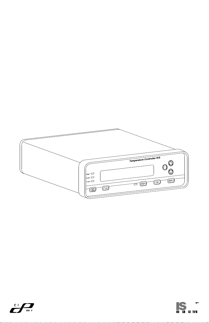
This manual provides information for installing and operating the Temperature Controller R/S (advanced model).
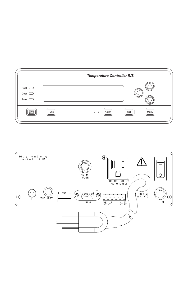
Refer to Figure 1 for a vie w of the front panel of the Temperature Controller R/
S. Refer to Figures 2 and 3 for a view of the back panels of the 115 V or 230
V versions.
FIGURE 1. TEMPERATURE CONTROLLER R/S
FIGURE 2. TEMPERATURE CONTROLLER R/S, BACK PANEL
(115 V MODEL)
2
Page 7

FIGURE 3. TEMPERATURE CONTROLLER R/S, BACK PANEL
(230 V MODEL)
APPLICATION DATA
Applications for the Temperature Controller R/S include heating and cooling
of solids, liquids, and gases. For all applications, there are certain set-up
operations that should be made carefully to assure optimum and safe perf ormance. The power and type of heater , the positioning of the sensor , the amount
of thermal insulation, the flash point of the heated material and the many
controller set-up menu options are among the many variables to be considered in setting up the controller.
One of the most important of these considerations is the heater sizing. A heater
that is too low powered ma y not be able to raise or ev en maintain the material at
the desired set point. A heater that is too high po wered will not maintain precise
temperature control and may be unsafe. Because of the many system variables, optimum heater sizing must be determined experimentally; howev er, an
approximation can be made through a fe w calculations . These calculations are
included in the software program included with the unit.
DESCRIPTION
GENERAL
The Temperature Controller R/S is designed to maintain a constant, pre-set
process temperature. It uses a temperature sensor to detect the temperature
of the process. Using a microprocessor softw are algorithm, it adjusts a heater
or cooler by varying the output duty cycle. The Temperature Controller R/S is a
single-loop controller intended for laboratory or industrial applications. The unit
can control loads of up to 15 amperes (A).
The Temperature Controller R/S is housed in a rectangular metal enclosure,
with plastic bezels on the front and back. All connections are made on the
rear of the unit. The display and keypad are on the front. A bail bar, or tilt
stand, is used to elevate the front display panel for easy viewing and opera-
3
Page 8
tion. The unit can also be mounted in a panel with the use of an optional panel
mount kit. A two-line, 16-character, 14-segment vacuum fluorescent display
is used for display of operating, setup, and alarm parameters.
A number of accessories can be used with this deluxe model of the Temperature Controller, including v arious types of temperature sensors, heating units,
cooling units (such as fans or pumps), remote alarms, and recorders.
One of several additional R/S model features (not available in the standard
models) is “Ramp and Soak,” which uses a timed sequence pre-set user
temperature set points.
The unit also has RS-232-C Serial Communications, so that it can be set up
and controlled by a computer. An IBM®-compatible PC (personal computer)
disk is included with the R/S controller, along with a separate operator's man ual.
It can be used to set up the controller and perform logging and other functions. For advanced users, a serial communications specification is included
on disk for customized programming.
CONTROL PANEL DESCRIPTION
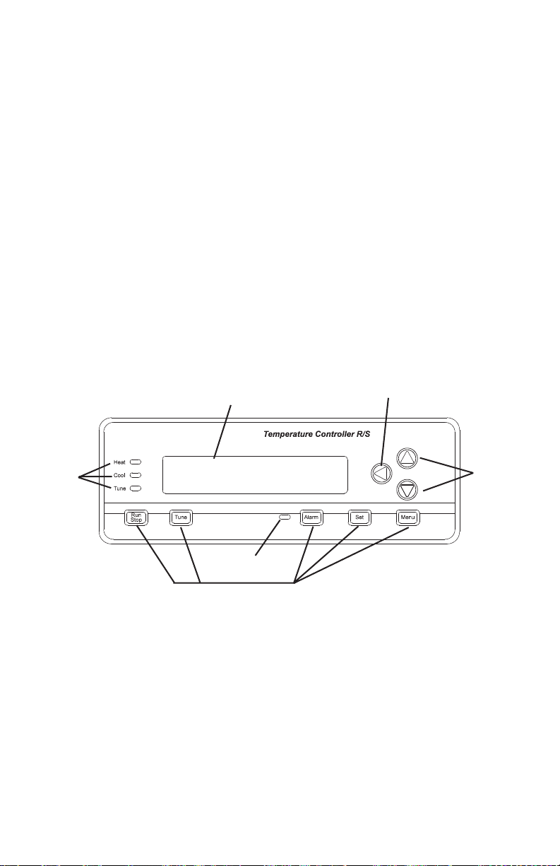
Refer to Figure 4 and the following paragraphs.
LEFT Arrow
UP and
DOWN
Arrows
Indicator
Lights
Readout Display
Alarm LED
Function Control Keys
FIGURE 4. FRONT PANEL DISPLAYS
Vacuum Fluorescent Readout
The vacuum fluorescent readout displays operation and setup parameters.
Alarm conditions are also displayed.
UP, DOWN, LEFT Arrows
The UP and DOWN arrow keys will increment or decrement the current values of displayed (blinking) numerals or enable you to scroll through a list
where multiple-choice parameters are offered. The LEFT arrow key allows
4
Page 9

you to change default numeric settings by moving the blinking cursor left to
the next most significant digit. When you have reached the most significant
digit (furthest left), the LEFT arrow key will move the flashing cursor back to
the least significant digit (furthest right).
MENU Key
The MENU key allows you to access all of the user-configurable setup parameters of the Temperature Controller. Pressing the MENU key will scroll
through the parameter options, using the arrow ke ys to change those parameters. Refer to the Setup Procedures section for additional information on
each parameter.
SET Key
The SET key allows y ou to change the control setpoint (SP), using the arrow
keys. Pressing the SET key again will exit the setpoint mode. In the Ramp
and Soak mode, the SET key will toggle the displa y between setpoint and run
time remaining. Refer to the Operation section for additional information on
changing the setpoint.
ALARM Key
The ALARM key enables y ou to acknowledge temperature control alarm conditions and silence the audible alarm. Pressing the ALARM k ey will erase any
alarm messages on the display and stop the ALARM from flashing. If the
alarm condition is still present, the ALARM LED will remain on until the PV
(process variable) is out of the alarm condition. If manual Reset mode is
selected in setup, the ALARM key will also de-energize the alarm relay.
Refer to Setup Procedures section for additional information on setting the
appropriate alarms.
TUNE Key
The TUNE key will start an AUTO tune cycle. Heat (or cooling) is automatically applied to determine PID values. AUTO tuning must be enabled in the
setup mode for this key to function. Refer to the AUTO Tuning section for
additional information on this setting.
NOTE: When the TUNE key is pressed, the output is turned full on three
times for a period of time and overshoot of the setpoint will occur.
Do not use the AUTO tune feature if this would have an adverse
affect on your process.
RUN/STOP Key
Pressing this key when the Temperature Controller is stopped will start the
control process and activate the load, if required. Pressing this k e y when the
Temperature Controller is r unning will cause it to stop.
5
Page 10

HEAT, COOL, TUNE LED Annunciators
These three indicators will light to indicate Temperature Controller functions.
The green HEAT light will tur n on when power is being applied to the heater
output. The g reen COOL light will turn on when the Temperature Controller is in
the cooling mode and power is applied to the cooler output. The yellow TUNE
light will turn on when the Temperature Controller is in the AUTO tuning mode .
How to Use this Product
Here is a summary of the steps required to setup and operate the Temperature Controller R/S.
1. Install the unit.
Setup your process.
Plug the Controller power cord to an AC outlet, turn unit on.
Plug the heater (or cooler) into the Controller rear panel and install in
your process.
Connect a sensor to the rear panel (thermocouple, RTD or thermistor)
and install in your process.
Optional installation connections:
Connect a recorder to the recorder contacts on the rear panel.
Connect an external alarm to the alarm output connection on the rear panel.
Connect a serial cable between the Controller RS232 connector and a
PC and follow the instructions for setup in the separate PC program operator manual.
2. Setup the operating parameters. Press MENU and follow the interactive
setup selections. If your setup is the same as the factory set defaults,
this step is not necessary . Howev er, each of the setup options should be
checked for desired or proper setting.
Set sensor type that was connected.
Select temperature scale.
Set alarms, if desired.
Calibrate system, if better accuracy is desired.
Set safety stops (over temperature and loop break).
Select control action and mode desired (PID, on/off or Ramp/Soak).
Setup recorder output temperatures, if a recorder is connected.
Set baud rate for serial connection, if a PC is connected.
3. Set the run temperature and begin controlling.
Press the SET key and enter the desired setpoint temperature.
Press TUNE if autotune is selected in setup and you want to automatically determine the PID settings.
Press the RUN/STOP key to begin temperature control.
The setpoint (SP) temperature and the actual temperature (or process
variable, PV) are displayed.
Press ALARM to acknowledge an alarm condition.
6
Page 11
INSTALLATION
INITIAL HARDWARE SETUP
1. Remove controller from packaging. K eep all packing material until proper
operation has been verified.
2. Use the "bail" bar (or tilt-stand) at the bottom of the unit to adjust position
for easy viewing of front panel.
Caution: To avoid electric shock, the power cord pro-
tective grounding conductor must be connected to earth-ground.
Caution: Install an independent temperature limit con-
trol protection system where a fault condition
could result in fire or other hazard. Failure to
install such a system could result in injury to
personnel or damage to property.
3. Plug the unit in to a correctly rated AC outlet and turn on the power using
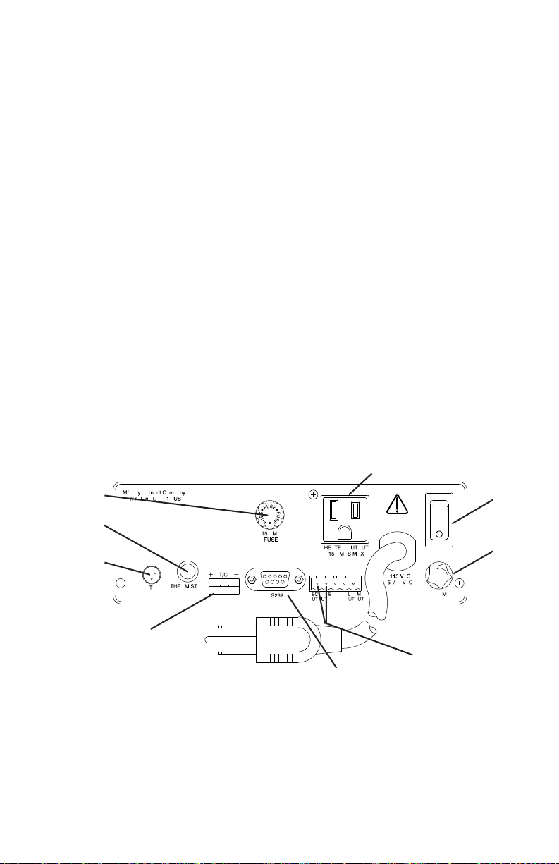
the ON/OFF switch on the back panel. Refer to Figure 5.
Heater Cord
Cable Connection
Heater/Cooler
Output Fuse
Thermistor
Probe Jack
3 Wire RTD
Probe Jack
ON/OFF
Switch
Main
Power
Fuse
Mini-ANSI Thermocouple
Jack (500 ohm Max
Load Resistance)
RS-232-C Serial
Connector
115 V
FIGURE 5. 115 V BACK PANEL
7
Recorder Output
Isolated 4-20 mA
Page 12
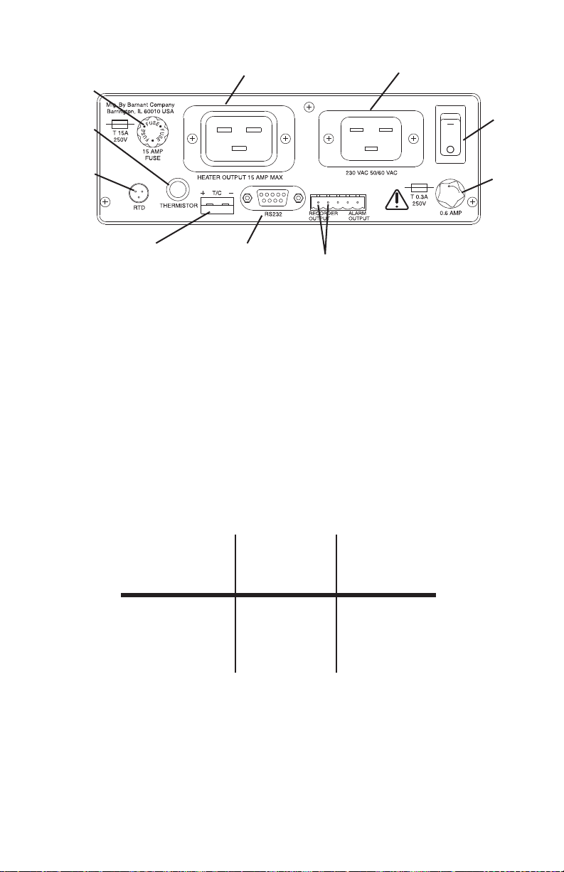
Heater/Cooler
Output Fuse
Thermistor
Probe Jack
Heater Cord
Cable Connection
Line Cord
Connection
ON/OFF
Switch
3 Wire RTD
Probe Jack
Mini-ANSI Thermocouple
Jack (500 ohm Max
Load Resistance)
RS-232C Serial
Connector
Recorder Output
Isolated 4-20 mA
Main
Power
Fuse
230 V
FIGURE 5. 230 V BACK PANEL
4. Connect one of the three types of sensors to the unit (refer to Accesso-
ries section for a listing of compatible probes).
5. Connect the heater or cooler (maximum of 15 A) to the unit.
6. Install the PC (personal computer) cable to the RS-232-C serial communications terminal, if desired. Refer to your PC hardware guide for PC
connections.
7. The following charts show the required connections for interfacing to an
IBM-compatible computer with either a 9-pin or 25-pin plug. The cables
listed in the Accessories section are properly wired for use.
Temperature
Controller Computer Computer
DB-9 DB-9 DB-25
Pin 2 Pin 3 Pin 2
Pin 3 Pin 2 Pin 3
Pin 5 Pin 5 Pin 7
RS-232-C Connection Chart
NOTE: The serial data format is full duplex, 1 start bit, 8 data bits, no
parity, and 1 stop bit. The baud rate is user-selected.
8
Page 13

8. Recorder output and alarm output devices may be installed on the temperature controller (refer to Figure 5). The 4/20mA recorder output is
designed for a left positive (+) and a right negative (-) connection. Alarm
output is designed for a left–NO (normally open), center–COM (common), and right–NC (normally closed) connector.
SETUP PROCEDURE
NOTES: a. At any time during the setup procedure, you may return to
the previous screen by pressing and holding down the LEFT
arrow key and then pressing the MENU key.
b. For experienced operators, a flow chart may be used for set-
up. Refer to Appendix A.
c. The setup mode can only be entered when the Temperature
Controller is stopped.
1. Set the ON/OFF switch on the rear panel to ON. The LEDs will light and
all segments will light temporarily as a check of the display.
2. After the diagnostics are complete, the Temperature Controller will display the unit identification screen (refer to Figure 6).
TEMPERATURE
CONTROLLER
FIGURE 6. UNIT IDENTIFICATION SCREEN
This screen will be displayed for a few seconds. The unit will automatically progress to the RUN screen.
3. Press MENU once to begin the setup process.
Sensor Types
1. To select a sensor type, press the DOWN arrow key. The following
screen will appear, with the default, or last selected, sensor indicated (refer to Figure 7).
SENSOR TYPE
THERMOCOUPLE
FIGURE 7. SENSOR TYPE SELECTION SCREEN
9
Page 14

2. Press the DOWN arrow ke y to select one of the three sensor types,
which are described as follows:
Thermocouple
1. To select a thermocouple type, press the MENU key (refer to Figure 8).
2. The screen will display the last thermocouple selected. To chose another thermocouple type, press the DOWN arrow key to move forward
or, if passing a desired selection, the UP arrow key to move backward.
Thermocouple selections include: K, J, E, B, T, S, R, and N.
3. Select the thermocouple type by pressing the MENU key. To ensure
proper operation, be sure that the correct thermocouple type is connected at the thermocouple jack before running the program.
THERMOCOUPLE
TYPE J
FIGURE 8. THERMOCOUPLE SELECTION SCREEN
Thermistor
1. The second sensor type available is the thermistor . Press the MENU key
at the SENSOR TYPE - THERMISTOR screen to display the following
screen (refer to Figure 9).
2. Use the UP or DOWN arrow key to chose either YSI 400 or YSI 700
thermistors.
3. After selecting the correct thermistor, press the MENU key.
THERMISTOR
YSI 400
FIGURE 9. THERMISTOR SELECTION SCREEN
10
Page 15

Platinum RTD
1. The Platinum RTD is the third sensor type that can be selected. Press
the MENU key at the SENSOR TYPE - PLATINUM RTD screen and the
following screen will appear (refer to Figure 10).
2. Select either Alpha .003850 or Alpha .003916. Select an Alpha of 0.003850
(default setting) for all probes listed in the Accessories section.
3. After selecting the platinum RTD type, press the MENU key to advance
to Temperature Scale selection.
100 OHM RTD
ALPHA .003850
FIGURE 10. PLATINUM RTD SELECTION SCREEN
Temperature Scale
1. After pressing the MENU key in the SENSOR-TYPE screen, the
program will progress to the Temperature Scale selection. The Temperature scale selection has five temperature scales from which to
choose: Celsius (°C), F ahrenheit (°F), Reaumur (°R'), Rankine (°R),
or Kelvin (K). Refer to Figure 11.
2. Press the DOWN arrow ke y to switch to a desired temperature scale.
Press the MENU key to select the appropriate scale.
TEMP SCALE
FAHRENHEIT °F
FIGURE 11. TEMPERATURE SCALE SELECTION SCREEN
11
Page 16

Alarm Selections
1. Alarms will activate only when the Temperature Controller is in the RUN
mode. When an alarm occurs, the alarm relay will energize, the alarm
LED will flash, the audible alarm will sound intermittently and the display
will flash the type of alarm. There are three possible alarm mode selections: MANUAL RESET, AUTO RESET, or OFF. Refer to Figure 12.
2. If you select ALARM SETPOINTS - OFF, no process or deviation alarms
will actuate. Both AUTO RESET and MANUAL RESET will result in alarms
actuating. If you select AUTO RESET, the relay will automatically shut off
when the PV temperature falls out of the alarm setpoint temperature. For
MANUAL RESET, the alarm relay is turned off when the ALARM key is
pressed. The alarm LED remains on until the alarm condition clears. For
both AUT O and MANU AL, the flashing message and the audible alarm are
turned off.
ALARM SETPOINTS
[SELECTIONS]
FIGURE 12. ALARM SETPOINTS SELECTION SCREEN
3. The first Alarm screen will display ALARM SETPOINTS - MANUAL RESET. Refer to Figure 13.
ALARM SETPOINTS
MANUAL RESET
FIGURE 13. ALARM SETPOINTS MANUAL RESET SCREEN
4. To go to the Auto Reset Screen, press the DOWN arrow key. Refer to
Figure 14.
ALARM SETPOINTS
AUTO RESET
FIGURE 14. ALARM SETPOINTS AUTO RESET SCREEN
12
Page 17

5. To select an automatic alarm reset, press the MENU key when the Auto
Reset screen is blinking.
6. To go to the Alarms Off Screen, press the DOWN arrow key. Refer to
Figure 15. If selected, refer to Alarms Auto Reset procedure, below.
ALARM SETPOINTS
OFF
FIGURE 15. ALARM SETPOINT OFF SCREEN
7. To select alarms off, press the MENU key when the ALARMS - OFF
screen is blinking.
8. After alarm selection, press the MENU key to move on to Alarm Hysteresis. After setting Alarm Hysteresis, press the MENU k e y again to mo ve
on to the Audible Alarm screen.
Process Alarms
Process alarms are absolute values. These v alues remain the same no matter what the setpoint temperature is set to. For example: if the operator sets
an alarm to trigger at 60 degrees Celsius and the SP (setpoint) temperature
is set at 55 degrees Celsius, the alarm will trigger at 60 degrees. If the oper ator resets the SP temperature to 57 degrees, then the process alarm value
will stay at the already set 60 degrees.
There are three types of process alarms: PROCESS HI, PROCESS LO , and
PROCESS HILO. Refer to the following paragraphs for more information.
Process HI
1. Process HI is a fixed value and will not change if the SP temperature
value is changed. It activates the alarm when the PV temperature exceeds the set alarm temperature. Ref er to Figure 16. If the Control Action
is set to COOL and the PV temperature exceeds the alarm temperature
when the RUN key is pressed, the alarm will not be activated. The PV
temperature must first fall below the alarm temperature before the high
alarm is enabled. This allows for normal system startup without activating the alarm.
ALARM MODE
PROCESS - HI
FIGURE 16. PROCESS HI SCREEN
13
Page 18

2. Select the PROCESS - HI screen by pressing the MENU key. The f ollowing screen will appear (refer to Figure 17). Set the Process HI temperature by using the arrow keys.
PROCESS ALARM
HI XXXXX °F
FIGURE 17. PROCESS HI SETTINGS SCREEN
Process LO
1. Process LO is a fixed value and will not change if the SP temperature
value is changed. It activates the alarm when the PV temperature drops
below the alarm temperature. Refer to Figure 18. If the Control Action is
set to HEAT and the PV temperature is below the alar m temperature
when the RUN key is pressed, the alarm will not be activated. The PV
temperature must first rise above the alarm setpoint before the low alarm
is enabled. This allows for normal system startup without activating the
alarm.
ALARM MODE
PROCESS - LO
FIGURE 18. PROCESS LO SCREEN
2.Select the PROCESS - LO screen by pressing the MENU key. The following screen will appear (refer to Figure 19). Set the Process LO temperature by using the arrow keys.
PROCESS ALARM
LO 000XX °F
FIGURE 19. PROCESS LO SETTINGS SCREEN
14
Page 19

Process HILO
1. Process HILO is a fixed value (a fixed high and a fix ed low alarm setpoint)
and will not change if the SP temperature value is changed. The purpose
for process HILO is to set the fixed HI and LO value at which to trigger
the alarm relay. Ref er to Figure 20. Refer to the Process HI and Process
LO sections for detailed descriptions of the operation of each alarm
setpoint.
ALARM MODE
PROCESS HILO
FIGURE 20. PROCESS HILO SCREEN
2. Select PROCESS - HILO by pressing the MENU key . The follo wing screen
will appear (refer to Figure 21). Set the alarm temperatures by using the
arrow keys . Once the first alarm value is set, press the LEFT arrow key to
adjust for the other alarm variable.
PROCESS ALARM °F
HI XXXX.X LO XXXX.X
FIGURE 21. PROCESS HILO SETTINGS SCREEN
Deviation Alarms
Deviation alarms are offset values relative to the setpoint (SP). The values
change with the SP temperature setting. F or e xample: if an operator sets the
deviation HI alarm to 10 degrees Fahrenheit and the SP temper ature is at 50
degrees Fahrenheit, the alarm will trigger when the PV reaches 60 degrees
Fahrenheit. If the operator then changes the previously set SP temperature
to 55 degrees Fahrenheit, then the alarm will trigger at 65 degrees Fahrenheit. The 10-degree Fahrenheit difference stays the same.
There are four possible deviation alarms settings: DEVIATION LO, DEVIATION HI, DEVIATION HILO, and DEVIATION BAND. Refer to the following
paragraphs.
15
Page 20

Deviation LO
Deviation LO adjusts the alarm value as the SP temperature value is adjusted.
Whatever value deviation LO is set at, it will remain the same until changed.
Refer to Figure 22.
ALARM MODE
DEVIATION LO
FIGURE 22. DEVIATION LO SCREEN
For example: if the Deviation LO value is set for 10 degrees Fahrenheit and
the SP temperature is set for 50 degrees Fahrenheit, the alarm will trigger at
40 degrees Fahrenheit. If the SP temperature v alue is changed to 45 degrees
Fahrenheit, the De viation LO will trigger the alarm at 35 degrees F ahrenheit.
If the Control Action is set to HEAT and the alarm condition exists when the
RUN key is pressed, the alarm will not be activated. The PV temperature
must first rise above the alarm setpoint before the alarm is enabled. This
allows for normal system startup without activating the alarm.
Select the DEVIATION - LO screen by pressing the MENU key . The following
screen will appear (refer to Figure 23). Move the cursor to the left using the
LEFT arrow key. When the setting is correct, press the MENU key to enter
that setting and to move the program to the alarm hysteresis screen.
DEVIATION ALARM
LO XXXXX °F
FIGURE 23. DEVIATION LO SETTINGS SCREEN
Deviation HI
Deviation HI will adjust the alarm value as the SP temperature value is adjusted. Whatever value Deviation HI is set at, it will remain the same until
changed. Refer to Figure 24.
ALARM MODE
DEVIATION HI
FIGURE 24. DEVIATION HI SCREEN
16
Page 21

For example: if the Deviation HI value is set for 10 degrees Fahrenheit and the
SP temperature is set for 50 degrees Fahrenheit, the alarm will trigger at 60
degrees Fahrenheit. If the SP temperature value is changed to 55 degrees
Fahrenheit, the de viation HI will not trigger the alarm until it reaches 65 degrees
Fahrenheit. If the Control Action is set for COOL and the alarm condition exists
when the RUN key is pressed, the alarm will not be activated. The PV temperature must first fall below the alarm setpoint to enable the high alarm. This allows
for normal system startup without activating the alarm.
Select DEVIATION - HI by pressing the MENU key. The following screen will
appear (refer to Figure 25). Set the Deviation HI temperatures by using the
arrow keys. Once the alarm value is set, press the MENU key to advance to
one of the other alarm variables.
DEVIATION ALARM
HI XXXXX °F
FIGURE 25. DEVIATION HI SETTINGS SCREEN
Deviation HILO
1. Deviation HILO allows the operator to set the alarm to actuate below and
above the SP temperature. Refer to Figure 26.
ALARM MODE
DEVIATION HILO
FIGURE 26. DEVIATION HILO SCREEN
For example: if the SP temperature is set at 50 degrees Fahrenheit and
the operator sets the Deviation HILO v alue at 10 degrees F ahrenheit, the
alarm will sound below 40 degrees Fahrenheit and above 60 degrees
Fahrenheit. To allow for normal system startup, the alarm may not be
activated under certain conditions. Refer to the DEVIATION HI and DE-
VIATION LO sections for additional information on alarm activation.
17
Page 22

2. Select the DEVIATION- HILO screen by pressing the MENU key. The
following screen will appear (refer to Figure 27). Set the Deviation temperature by using the arrow keys.
3. After selecting values, press the MENU key to continue.
DEVIATION ALARM
HI/LO XXXXX °F
FIGURE 27. DEVIATION HI/LO SETTINGS SCREEN
Deviation BAND
1. Deviation BAND allows the operator to set the alarm to sound while the
temperature is in a temperature window. Refer to Figure 28.
ALARM MODE
DEVIATION BAND
FIGURE 28. DEVIATION BAND SCREEN
For example: if the SP temperature is set for 50 degrees and the Deviation BAND is set for 25 degrees, the alarm will trigger at 25 degrees and
continue to sound up to 75 degrees. In this example , the alarm window is
25 degrees below 50 and 25 degrees above 50.
2. Select DEVIA TION BAND by pressing the MENU key . The following screen
will appear (refer to Figure 29). Set the Deviation BAND temperature
value by using the arrow keys. Once the value is set, press the MENU
key to advance to Alarm Hysteresis.
DEVIATION ALARM
BAND XXXXX °F
FIGURE 29. DEVIATION BAND SETTINGS SCREEN
18
Page 23

Alarm Hysteresis
1. Alarm Hysteresis deter mines when the alarm is going to be out of the
alarm condition. Alarm hysteresis prevents actuation of nuisance, or recurrent, alarms. Hysteresis is either added or subtracted to the alarm
point, depending on whether a HI or LO ALARM has been set.
For example: If hysteresis is set at 1 degree and the HI alarm has been
set to trigger when the temperature reaches 100 degrees Fahrenheit, the
alarm will trigger at 100 degrees. As soon as the temperature drops below 99 degrees the alarm condition will terminate.
2. Set the hysteresis by using the arrow keys.
ALARM HYSTERESIS
XXX.X °F
FIGURE 30. ALARM HYSTERESIS SCREEN
3. After selecting values, press the MENU key to continue.
Audible Alarms
Audible Alarm permits the sound of an alarm. It has two options: On or Off.
Use the arrow keys to select an option and press the MENU key to advance
to the Advanced Setup MENU. Refer to Figure 31.
AUDIBLE ALARM
ON
FIGURE 31. AUDIBLE ALARM SCREEN
19
Page 24

Advanced Set-Up
1. After pressing the MENU button, the ENTER ADVANCED SETUP screen
will be displayed (refer to Figure 32).
2. The flashing message YES will ask if you want to enter the Advanced
Screen. Press the MENU key as the word YES blinks.
NOTE: If a change to that selection is not chosen within 3 seconds, the
program will automatically exit the setup mode.
ENTER ADVANCED
SETUP MENU YES
FIGURE 32. ADVANCED SETUP SCREEN
Sensor Calibrate
1. Sensor Calibrate enables the operator to calibrate out sensor error to
give a more accurate reading. Refer to Figure 33. Calibration offset and
PV (actual) temperatures are displayed.
SENSOR OFFSET
CAL ±XX.X XXX.X °F
FIGURE 33. SENSOR CALIBRATE SCREEN
2. To adjust the values in this option, the operator must know how many
degrees off the sensor is. To deter mine how far off the sensor is, measure it against a secondary gauge known to be accurate.
3. Once the value is known, adjust the CAL offset value on the screen using
the arrow keys until the displayed temperature matches the known temperature. Press the MENU key to advance to the Over temp screen.
(Refer to Figure 34.)
NOTE: Calibration can also be done using an ice bath or boiling water
and adjusting the offset until 32.0 °F or 212 °F is displayed.
20
Page 25

Over Temp Stop
1. Over temp stop temperature, a safety feature, is added to the setpoint
(SP) temperature. If the PV temperature exceeds this amount, the Temperature Controller will stop. Over temp stop does not operate if the COOL
control action is selected. Refer to Figure 34.
OVER TEMP. STOP
XX °F ABOVE SP
FIGURE 34. OVERTEMP SCREEN
2. To change the Overtemp value, use the arrow keys. After the value has
been set, press the MENU key to adv ance to the Loop Break Stop Screen.
Loop Break Stop
Loop break stop, a safety feature, is designed to stop the Temperature
Controller if the heater output is on for the amount of time set in Loop Break
Stop and the PV temperature does not increase more than 1.0 °F. If the
COOL control action is selected, it is stopped if the PV temperature does not
decrease more than 10°F. Refer to Figure 35.
LOOP BREAK STOP
XXX.X MINUTES
FIGURE 35. LOOP BREAK STOP SCREEN
Loop break stop is designed to terminate the process currently running if the
process is interrupted for a preset period of time. The loop break stop senses
that nothing is happening in the process and turns the process off.
Enter an elapsed time using the UP and DOWN arrow keys. For slow systems, a longer time should be entered.
21
Page 26

Control Action
1. The Control Action screen allows selection of the type of process that will
be performed; either HEAT or COOL. Refer to Figure 36. In the heat
mode, the output is on when the actual temperature is below the setpoint
temperature (inverse action). In the cool mode , the output is on when the
actual temperature is above the setpoint temperature (direct action).
CONTROL ACTION
HEAT
FIGURE 36. CONTROL ACTION SCREEN
2. The default setting is HEAT. Use the DOWN arrow key to select either
heat or cool actions. Press the MENU key to enter your selection.
Control Mode
1. The Control screen has three options: PID (proportional band, integral
and derivative), Ramp and Soak, and ON/OFF. Refer to Figure 37.
CONTROL MODE
PID
FIGURE 37. CONTROL SCREEN
2. Select one of these options using the arrow keys. When the desired
option appears on the screen, press the MENU key. Refer to the PID or
Ramp and Soak procedural paragraphs, f ollowing, for additional inf ormation.
22
Page 27

Control Mode On/Off
1. The Control Mode On/Off turns off the output when the actual temperature exceeds the setpoint (heat control action). The output will turn on
when the actual temperature falls below the setpoint temperature min us
the hysteresis temperature. Refer to Figure 38.
ON/OFF CONTROL
HYSTERESIS XX.X °F
FIGURE 38. ON/OFF CONTROL HYSTERESIS SCREEN
2. Adjust the hysteresis value on this screen using the arrow keys.
3. Press the MENU key to advance to the RUN TIME Screen.
PID - Proportional Band, Integral and Derivative
PID is the means of selecting the response speed or sensitivity of a proportioned controller to achieve stability in the system. It should be used when
system stability or accuracy requirements are too great for use of on/off control.
NOTE: PID Settings should not be changed from the manufacturers
AUTO TUNE settings unless the operator has advanced training
in the understanding of PID.
AUTO Tune
1. After selecting the PID screen the next screen to appear will be AUTO
TUNE. Refer to Figure 39. Two choices are available for this selection:
AUT O TUNE ENABLED and A UT O TUNE DISABLED . The recommended
choice for this screen is AUTO TUNE ENABLED.
The default setting is ENABLED. Use the DOWN arrow key to select
either enabled or disabled. Press the MENU key to enter your selection.
NOTE: When AUTO TUNE DISABLED is selected, auto tuning cannot be
initiated using the TUNE key on the front panel.
AUTO TUNE
ENABLED
FIGURE 39. AUTO TUNE SCREEN
23
Page 28

2. Select an option using the arrow keys.
3. If AUT O TUNE ENABLED is selected, press the MENU k e y f our times to
advance past the PID setup to the RUN TIME screen.
NOTE: AUTO TUNE DISABLED is also a safety feature to prevent
accidental auto tuning.
Proportional Band
1. Select the proportional band by pressing the MENU key. The following
screen will appear (refer to Figure 40).
PROPORTIONAL
BAND XXXX °F
FIGURE 40. PROPORTIONAL BAND SCREEN
2. Use the arrow keys to enter the correct value and press the MENU key.
Integral Time
1. Integral time, measured in seconds per repeat, is tuned to correct for the
droop (difference between setpoint and steady state actual temperatures)
that is caused by the proportional output. Refer to Figure 41.
INTEGRAL TIME
XXXX SECONDS
FIGURE 41. INTEGRAL SCREEN
2. Use the arrow keys to enter the correct value and press the MENU key.
24
Page 29

Derivative Rate
1. The derivative rate reduces or eliminates overshoot. Refer to Figure 42.
It is measured in seconds and must be tuned to work with the overall
system cycle time.
DERIVATIVE RATE
XXXX SECONDS
FIGURE 42. DERIVATIVE SCREEN
2. Use the arrow keys to enter the correct value and press the MENU key.
Ramp and Soak
Ramp and Soak is a means of automatically increasing or decreasing setpoint
temperatures within specific time periods using an operator pre-set program.
By setting the values on the segment screens an operator can tell the temperature controller to ramp up or down 16 levels.
1. The Ramp and Soak screen offers a selection of nine profiles which can
be changed, if required. Each profile has 16 possible segments.
2. Use the arrow keys to select a profile. Refer to Figure 43.
RAMP & SOAK
PROFILE X
FIGURE 43. RAMP AND SOAK SCREEN
3. Press the MENU key to advance to the segment setup.
25
Page 30

Assured Soak
Assured Soak applies only to Ramp and Soak. Refer to Figure 44. In select-
ing Assured Soak, each segment is extended until the actual temperature
reaches the setup temperature specified in that segment (before moving on
to the next segment). If Assured Soak is not selected, then the unit adv ances
to the next segment at the specified time, whether or not the specified temperature has been reached. This will not be a factor if a heating or cooling
element is properly sized for the material to be acted upon.
1. Use the arrow keys to select YES or NO.
2. Press the MENU key to advance to segment definition.
ASSURED SOAK
YES
FIGURE 44. ASSURED SOAK SCREEN
SEG XX 0000 °F
HR XX MIN XX CP X
FIGURE 45. PROFILE ALTERATION SCREEN
Segment Definition
The segment temperature displayed indicates the desired temper ature at the
end of the segment time. The starting temperature will be the temperature
from the previous segment, except for segment 01, which will be the current
sensor temperature.
The end of a ramp and soak occurs when segment 16 is completed, or when
a segment with 0 HR and 0 MIN is reached.
The Temperature Controller will continue running at the last specified temperature until the RUN/STOP key is pressed.
1. Adjust the Segment number using the arrow keys. There are 16 possible
segments.
2. As each segment number is changed, adjust the segment end temperature value and the time values using the arrow keys. In the bottom, right
corner of the Segment Screen is the CP (Control Parameter) number.
26
Page 31

Each CP number represents a set of proportional band, integral time, and
derivative rate v alues. This is included f or con v enience in setting ramp and
soak PID values when individual segments hav e different stability requirements. Specific CP values are set in Control P ar ameters, below. Selecting
CP 0 will assign the auto tune PID values to the segment.
3. Press the MENU key to advance to CP setup.
Control Parameters (CP)
1. Nine control parameter numbers are available for storing up to nine sets
of PID values. The PID values can be determined experimentally but
auto tune values can be used by selecting CP 0. Use the arrow keys to
set the P, I, and D values for that CP value.
2. Press the MENU key to advance to Cycle Time set up.
Cycle Time
Cycle Time will only appear after progr amming the Ramp and Soak and PID
functions. Cycle time is the rate at which output is cycled or changed. The
manufacturer's recommended cycle time is 1 second. If using a mechanical
relay in the process, it is recommended to increase the cycle time to reduce
the number of cycles a relay would have to endure. Refer to Figure 46.
CYCLE TIME
XXXX SECONDS
FIGURE 46. CYCLE TIME SCREEN
1. Use the DOWN arrow key to increment the time period desired.
2. Press the MENU key to advance to the Recorder Out screen.
Run Time
Run Time is a safety feature that sets the Temperature Controller operating
time in the on/off and PID control modes. When the set v alue is reached, the
output is turned off. To disable this feature, select CONTINUOUS b y entering
a run time of HR00 MIN00. Refer to Figure 47.
RUN TIME
HR XX MIN XX
FIGURE 47. RUN TIME SCREEN
27
Page 32

1. Use the DOWN arrow key to increment the time period desired.
2. Press the MENU key to enter your selection.
Recorder Output
Recorder Out consists of two selections: Recorder Out at 4mA and Recorder Out at 20mA screens. Refer to Figure 48. This function allows the
operator to scale the temperature between 4mA and 20mA, to allow proportional scaling of the recorder output.
RECORDER OUT AT
4MA XXXX.X °F
RECORDER OUT AT
20MA XXXX.X °F
FIGURE 48. RECORDER OUT SCREENS
1. Adjust the temperatures to be equivalent to 4mA using the arrow keys.
2. Advance from the 4mA screen to the 20mA screen by pressing the MENU
key and set the temperature to be equivalent to 20mA.
3. After adjusting the 20mA screen, press the MENU key to advance to the
SERIAL BAUD MENU.
Serial Baud
Six baud rates are availab le for communicating ov er the serial port: 300, 600,
1200, 2400, 4800, and 9600. Refer to Figure 49. Select the highest number
compatible with your PC.
SERIAL BAUD
RATE XXXX
FIGURE 49. SERIAL BAUD SCREEN
28
Page 33

1. Set the SERIAL BAUD rate using the arrow keys.
2. Press the MENU key to advance to the POWER UP CONTROL screen.
Power Up Control
This set up option allows you to specify one of two conditions for the Temperature Controller at turn on. Power Up Control has two options: Last State
and Stopped. Refer to Figure 50.
POWER UP CONTROL
LAST STATE
FIGURE 50. POWER UP CONTROL SCREEN
The two selections are designed primarily to function in the event of a power
failure. If a power outage occurs, Last State will start the process from where
it last ended when the power went out, Stopped will leave the process off.
When a run time has been entered or the unit is in the RAMP and SOAK
mode, it will always power-up in the STOPPED mode.
1. Use the arrow keys to select one of the options and press the MENU ke y
to advance to the ADVANCED SET UP COMPLETE screen.
2. Once at this screen, the unit will automatically default to a message screen
which says SA VING SETUP. Setup is complete, and the operation screen
will be displayed.
29
Page 34

OPERATION
Once installation and setup are complete, press the RUN/ST OP ke y to begin
operation. The following screen will appear (refer to Figure 51) if a previous
run was stopped before it completed.
RUN OPTION
CONTINUE/RESTART
FIGURE 51. RUN SCREEN
Select either CONTINUE or RESTART using the arrow keys and then press
RUN/ST OP key. CONTINUE will start a run at the point where it was stopped.
RESTART will reset the run time and start at segment 1 if in Ramp and Soak
mode. The information displayed during the RUN mode will depend on the
setup options selected. General display functions for each mode are shown
below. Depending on the ALARM options set, alarm conditions will be displayed and alarms will sound.
CONTROL MODE
If you selected Control Mode On or PID during setup, the following screen
will appear. Ref er to Figure 52. Press SET to enter desired setpoint temperature.
PV XX.X °F
SP XX.X XX_XX_XX
FIGURE 52. DISPLAY OF PROCESS VARIABLES/
SETPOINT IN CONTROL MODE - ON
The display shows the PV (process va riable), the SP (setpoint), and the time
remaining. Time remaining will not appear if CONTINUOUS is selected for
RUN TIME.
30
Page 35

RAMP AND SOAK MODE
If you selected Ramp and Soak during the setup, the following screen will
appear (refer to Figure 53).
XX.X °F SEG X
XX_XX_XX RAMP
FIGURE 53. TEMPERATURE/TIME/SEGMENT DISPLAY
FOR RAMP/SOAK MODE
During the ramp and soak operation, the temperature, segment number, time
remaining, and status (i.e., RAMP or SOAK) will be displayed.
To advance to the next segment, press and hold down the RUN/STOP key
until the displayed segment number advances (about 3 seconds).
Setpoint or time remaining can be displayed by pressing the SET key.
V
31
Page 36

TROUBLESHOOTING AND MAINTENANCE
Warning: There are no user-serviceable parts in this
instrument. Do not remo ve cover , as high voltages exist inside the unit. Refer servicing to
your dealer.
Warning: If thermocouples are at a high voltage, this
voltage will be present at other points inside
the unit.
TROUBLESHOOTING
If the heater output does not function correctly , chec k the fuse located on the
rear of the unit left of the heater output receptacle. The fuse is rated at 15 A.
Replace it with a fuse having identical voltage and current ratings.
Caution: For contin ued fire protection, replace fuse onl y
with a fuse of the specified current, voltage,
and type. Remove power cor d from wall socket
before checking or replacing a fuse. High voltages exist on fuse terminals.
If the unit does not have power, check the fuse located below the ON/OFF
switch. The fuse is rated at 0.6 A for 115 V applications and 0.3 A for 230 V
applications. Replace this fuse with a fuse having identical voltage and current ratings.
CALIBRATION
System calibration is described in the setup portion of this manual. Instrument calibration is completed at the factory. No user calibr ation is required to
meet stated specifications.
MAINTENANCE/CLEANING
Maintenance is limited to fuse replacement. All materials withstand standard
cleaning solvents.
32
Page 37

SPECIFICATIONS
Display: Two lines of 16 characters. Four-digit
process value. Four-digit setpoint value .
Accuracy:
Type J,K,T,E and N
above −100°C (−148°F): ±0.1% reading, ±0.4°C (±0.7°F)
below −100°C (−148°F): ±0.1% reading, ±1°C (±1.8°F)
Type R,S and B
±0.1% reading, ±1°C (±1.8°F)
Thermistor, RTD
±0.1% reading, ±0.4°C (±0.7°F)
Resolution: 0.1° auto-ranging to 1° above 999.9
Environment:
Temperature, Operating: 0 to 40°C
Temperature, Storage: −20 to 70°C
Temperature, Specification: 18 to 28°C
Humidity: 10 to 90% RH (non-condensing)
Altitude: less than 2000 m
Pollution Degree: Pollution degree 2 per IEC 664
(Indoor Usage—lab, office)
Warm-Up time: 10 minutes
Construction:
Dimensions: W:7.3 in H:3.7 in D:10.0 in
Weight: 5.3 lbs
Enclosure: IP52 per IEC 529
Compliance:
115V and 230V: UL 916
230V (For CE Mark): EN61010-1/A2:1995 and
EN61010-2-010:1995
(EU Low Voltage Directive) and
EN61326-1/A1:1998
(EU EMC Directive)
Sensor Input Range/Accuracy:
Thermocouples Range
Type E: −200 to 1000°C (−328 to 1832°F)
J: −190 to 1000°C (−310 to 1832°F)
K: −200 to 1372°C (−328 to 2502°F)
N: −200 to 1300°C (−328 to 2372°F)
T: −200 to 400°C (−328 to 752°F)
B: 200 to 1800°C ( 392 to 3272°F)
R: 0 to 1768°C ( 32 to 3214°F)
S: 0 to 1768°C ( 32 to 3214°F)
33
Page 38

SPECIFICATIONS (Continued)
Thermistors:
YSI 400: −40 to 100°C ( −40 to 212°F)
YSI 700: −30 to 100°C ( −22 to 212°F)
Platinum RTD
100 ohm: −200 to 850°C (−328 to 1562°F)
INPUTS
AC Line Input
115V Model 230V Model
Input: 115V AC ±15%, 49/61 Hz 230V AC ±15%, 49/61 Hz
15A Max 15A Max
Connector: Standard Line Cord IEC 320 C-20 Inlet
Fuse: 0.630A/230V Slo-Blo 0.315A/230V Slo-Blo
(T) 5x20mm (T) 5x20 mm
Installation Category: Category II per IEC664
(Local level— appliances, portable equipment, etc.)
Thermocouple Probe Input
Connector: Mini-ANSI flat blade thermocouple jack
Calibration: ITS-90 (NIST monograph 175)
Lead resistance: 500 ohm max
Common mode voltage: 5 V max
Thermistor Probe Input
Any of the YSI series 400 and 700 series probes and YSI 44004, 44033,
44018 and 44104 composite thermistor elements.
Connector: 3-pin 1/4 in phone jack
CONTACT 400 series 700 series
TIP: Therm. Therm. (T1)
RING: not used Therm. (T2)
BARREL: Therm. Therms. (Common)
400 series 700 series
Calibration: YSI 44033 YSI 44018
Impedance: 2252 ohm @ 25°C (77°F) (T1) 6,000 ohm @ 25°C (77°F)
(T2) 30,000 ohm @ 25°C (77°F)
Interchangeability: ±0.10°C ±0.15°C
Lead Resistance: 0.45 ohm max 1.2 ohm max
Power Dissipation: 0.5 mW max 1.3 mW max
34
Page 39

Impedance: 2252 ohm @ 25°C (77°F) (T1) 6,000 ohm @ 25°C (77°F)
(T2) 30,000 ohm @ 25°C (77°F)
Interchangeability: ±0.10°C ±0.15°C
Lead Resistance: 0.45 ohm max 1.2 ohm max
Power Dissipation: 0.5 mW max 1.3 mW max
RTD Probe Input
Connector: 3-pin circular (mate to Switchcraft TA3F
plug)
Pin 1: RTD (–)
Pin 2: RTD (+) sense line
Pin 3: RTD (+)
Calibration: DIN IEC 751
Impedance: 100 ohm ±0.1 ohm @ 0°C (32°F)
Sensitivity: 0.003850 or 0.003916 ohm/ohm/°C
selectable
Lead Resistance: 30 ohm maximum each lead (balanced)
OUTPUTS
AC Line Output
115V Model 230V Model
Input: 115V AC typical, 15A max 230V AC typical, 15A max
Connector: NEMA 5-15R Reverse IEC 320-C20
Fuse: 15A/230V 3AG Slo-Blo 15A/230V 3AG Slo-Blo
Alarm Output
Output: Isolated Form C contact closure
Rating: Class 2 — 30 V AC/DC 2 A
Connector: Screw terminal
Recorder Output
Output: Isolated 4-20 mA
Resolution: 12 bit
Range: User scalable
Supply: Internal 26 VDC
Loop load: 1000 ohm max
Connector: Screw terminal
Serial Output
Output: Isolated RS-232-C serial communications
Mode: Bi-directional Male
Connector: 9-pin male D-sub connector
Pin 2: Receive
Pin 3: Transmit
Pin 5: Ground
All others not connected
35
Page 40

WARRANTY
Cole-Parmer Instrument Co. supplies this product with a ONE-YEAR warranty
to be free from significant deviations from published specifications. If repair or
adjustment is necessary within the warranty period, the problem will be corrected
at no charge if it is not due to misuse or abuse on your part as determined
by Cole-Parmer Instrument Co. Repair costs outside the warranty period, or
those resulting from product misuse or abuse,may be invoiced to you.
PRODUCT RETURN
To limit charges and delays, contact the seller or manufacturer for authorization and shipping instructions before returning the product, either within or
outside of the warranty period. When returning the product, please state the
reason for the return. For your protection, pack the product carefully and
insure it against possible damage or loss. Any damages resulting from improper packaging are your responsibility.
TECHNICAL ASSISTANCE
If you have an y questions about the use of this product, contact the manufacturer or authorized seller.
36
Page 41

APPENDIX A
Temperature Controller
Setup Mode for Advanced Model
A-1
Page 42

Temperature Controller
Setup Mode for Advanced Model
A-2
Page 43

APPENDIX B
The following is a list of error messages that may be displayed by the Temperature Controller and a description of corrective action.
Upper Lower
Display Display Action
normal OVER TEMP STOP PV exceeded OVER TEMP
STOP Setting in User Setup.
normal LOOP BREAK STOP No change in PV with output
on for user settable time
period. Adjust Loop Break Stop
in user setup.
normal OPEN PROBE STOP Detected open probe sensor
while running. Check probe.
normal OVER PROBE STOP PV exceeded the upper limit of
selected probe type.
normal UNDER PROBE STOP PV went below lower limit of
selected probe type.
NO OUTPUT CHECK 15 A No AC voltage detected at the
POWER FUSE heater output. Check the
heater/cooler output fuse. If
fuse is OK, return unit for
service.
INTERNAL SERVICE Return unit to your dealer.
ERROR # REQUIRED
B-1
Printed in U.S.A.
041001
Page 44

COLE-PARMER ADVANCED MODELS
89000-10 115V
89000-15 230V
Catalog # MODEL DESCRIPTION
89000-50 All models Panel Mount Kit
89000-98 All models Heater Sizing Software
89000-97 All models Alarm/Recorder Output Connector
89000-78 230V only Input Cord - IEC320/NEMA 6-15P
89000-80 230V only Input Cord - IEC320/BARE END
89000-95 230V only Heater Output Connector, IEC 16A
 Loading...