

Page 1
SPECIFICATIONS
Range: -58.0 to 1832.0 °F
-50.0 to 1000.0 °C
Resolution: 0.1°
OPERATION
Press and continue to hold down the trigger to
take temperature readings. The unit will take
temperature readings while the trigger is pressed
and held (SCAN ashing on the display indicates
measurements are being taken).
After the trigger is released, the last temperature
measured will be displayed for approximately 8
seconds, the display will then turn off automatically.
HOLD will appear on the display when the trigger
has been released to indicate that the unit is no
longer taking temperature measurements.
SWITCH LOCATIONS
The following switches are located in the handle:
°C/°F
LOCK ON/OFF
SET ALARM ON/OFF
To access these switches,
locate the indentions on
either side of the plastic
case near the trigger.
Open the handle by pulling
the rubber portion of the
handle out and away from
the trigger. Pull hard, it
requires a good amount of
force to open the handle.
Close the handle by snapping it shut.
SELECTING UNITS OF MEASURE
Locate the °C/°F switch inside the handle. Slide the
switch to °C to display the temperature in °C. Slide
the switch to °F to display the temperature in °F.
LASER TARGETING/BACKLIGHT
While pressing and holding the trigger, each press
ð
the /
button toggles through the following:
r
Backlight ON ( appears on the display)
Backlight and Laser Targeting ON ( and
ð
r
appear on the display)
Laser Targeting ON, Backlight OFF (
ð
r
appears
on the display)
Backlight and Laser Targeting OFF (no display
indicators)
With the backlight on, each time the trigger
is pressed and held, the LCD display will be
illuminated by the backlight.
With laser targeting on, each time the trigger is
pressed and held, the laser beam will be emitted.
CAUTION: Eye damage may result from direct
exposure to laser light.
DISTANCE SPOT/RATIO
There are other factors that may affect measurement
accuracy. The target must completely ll the spot
diameter seen by the infrared sensor; otherwise
readings will be inuenced by the surface
surrounding the target. The ratio of the distance to
the size of the spot being measured is 50:1. For
example, an object’s diameter of 100mm can be
measured from 5000mm.
VALUES RECORDED
With each press of the trigger, ve values are
recorded:
1. MAX - Highest temperature measured
2. MIN - Lowest temperature measured.
3. dIF - Difference between MAX and MIN
4. AVG - Time-weighted average temperature.
5. Value last displayed before releasing the trigger.
DISPLAY MODES
Each press of the MODE button will select one of
the 7 display modes. You can cycle through the
modes in this order:
“MAX” (Maximum temperature) - press the MODE
button until MAX appears on the display. In the
MAX mode the highest temperature measurement
taken is displayed to the right of MAX. This value
will update each time a higher temperature is
measured.
“MIN” (Minimum temperature) - Press the MODE
button until MIN appears on the display. In MIN
mode, the lowest temperature measurement taken
is displayed to the right of MIN. This value will
update each time a new lower temperature is
measured.
“dIF“ (Temperature differential between MAX and
MIN) - Press the MODE button until dIF appears
on the display. The difference between the MAX
and MIN reading is displayed to the right of dIF.
This value is updated as new MAX and MIN
temperatures are measured.
“AVG” (Calculated {time weighted} average
temperature)- Press the MODE button until AVG
appears on the display. The time weighted average
temperature reading is displayed to the right of
AVG. This value is updated continuously while
the trigger is being pressed.
The term “time”, in reference to the averaging
mode, means all temperature measurements
are averaged together from the rst press of
the trigger. Example: If the temperature was
72° for one minute, then 20° for 1/2 second, no
signicant change in average temperature would
be displayed.
“HAL” (High Temperature Alarm) - Press the
MODE button until HAL appears on the display.
The high temperature alarm value that has been
set is displayed to the left of HAL. (See High/
Low Alarms section)
“LAL” (Low Temperature Alarm) - Press the
MODE button until LAL appears on the display.
The low temperature alarm value that has been set
is displayed to the left of LAL. (See High/Low
Alarms section)
“EMS” - Emissivity adjustment mode (See the
Emissivity section).
NOTE: The last mode selected will remain selected
the next time the trigger is pressed.
MEMORY RECALL
With each press of the trigger, ve values are
recorded:
1. MAX - Highest temperature measured
2. MIN - Lowest temperature measured.
3. dIF - Difference between MAX and MIN
4. AVG - Time-weighted average temperature.
5. The value last displayed before releasing the
trigger.
To cycle through each of the values recorded
during the last measurement, press the MODE
button. (See the “Display Modes” section for an
explanation of the values displayed)
HI/LOW ALARMS
An audible alarm will sound at both an upper and a
lower temperature limit.
To adjust the alarm temperature set points:
1. Press the MODE button until “HAL” (High
Temperature Alarm) or “LAL” (Low Temperature
Alarm) is displayed.
2. To adjust the temperature alarm set point, press
the p or q button. (Do not press the trigger while
adjusting the alarm set points). Press and hold to
advance the display rapidly.
To turn the Hi/Low Alarm function On/Off:
1. Locate the SET ALARM ON/OFF switch in the
handle.
2. Slide the switch to the desired position.
With the Alarm function set to ON, (indicated by
(
(
(
and
HI
)
)
) appearing on the display), while
LOW
taking temperature measurements, an alarm will
sound when the temperature measured is above or
below the High and Low alarm set points that have
been entered. If the temperature is above the High
(
Alarm set point, (
(
will ash on the display. If
HI
the temperature is below the Low Alarm set point,
)
)
) will ash on the display.
LOW
The alarm will sound regardless of the Display
Mode if the temperature measured is above or
below the High and Low alarm set points that have
been entered.
LOCK FUNCTION
The lock function allows the thermometer to take
long term measurements without having to hold the
trigger. When the lock function is activated, the unit
will take continuous temperature measurements
until the LOCK function is set to OFF.
To use the lock function:
1. Locate the LOCK ON/OFF switch in the
handle.
2. Slide the switch to the ON position.
3. Close the handle.
4. Press and release the trigger to begin taking
measurements.
The unit will continue to take measurements
without holding the trigger until the LOCK ON/
OFF switch is set to OFF.
5. When nished taking measurements, locate
the LOCK ON/OFF switch in the handle.
6. Slide the switch to the OFF position.
7. Close the handle.
Find Quality Products Online at: sales@GlobalTestSupply.com
www.GlobalTestSupply.com
Page 2

EMISSIVITY
Emissivity adjustment is optional. Emissivity
adjustments are used to provide a truer
temperature reading. The emissivity value appears
at the top of the display (ε=#.##).
Different materials radiate infrared energy at
slightly different temperatures. The emissivity
adjustment is used to compensate for different
types of materials. The default emissivity of 0.95
will cover 90% of typical applications.
The emissivity table provides a guide of different
emissivity values for different materials.
When the emissivity of an object is unknown use
a non-infrared thermometer, such as a thermom-
eter with a surface probe to measure the object’s
surface temperature. Adjust the emissivity until
the temperature of the Infrared Thermometer
SURFACE ...........................................................EMISSIVITY
Iron and Steel
Cast iron (polished) ............................................................0.2
Cast iron (tumed at 100oC) ...............................................0.45
Cast iron (tumed at 1000oC) .....................................0.6 to 0.7
Steel (ground sheet) ...........................................................0.6
Mild steel ..................................................................0.3 to 0.5
Steel plate (oxidized) ..........................................................0.9
Iron plate (rusted) ...................................................0.7 to 0.85
Cast iron (rough) rusted ....................................................0.95
Rough ingot iron .................................................................0.9
Molten cast iron ..................................................................0.3
Molten mild steel .......................................................0.3 to 0.4
Stainless steel (polished) ....................................................0.1
Stainless steel (various) ...........................................0.2 to 0.6
Aluminum
Polished aluminum ........................................................... 0.1*
Aluminum (heavily oxidized) .............................................0.25
Aluminum oxide at 260oC ...................................................0.6
Aluminum oxide at 800oC ...................................................0.3
Aluminum Alloys, various ........................................0.1 to 0.25
Brass
Brass (polished) ................................................................ 0.1*
Brass (roughened surface) .................................................0.2
Brass (oxide) ......................................................................0.6
Copper
Copper (polished) ........................................................... 0.05*
Copper (oxide) ....................................................................0.8
Molten copper ...................................................................0.15
Lead
Lead (polished) ................................................................. 0.1*
Lead (oxide at 25oC) ...........................................................0.3
Lead (oxide) ........................................................................0.6
Nickel and Its Alloys
Nickel (pure) ..................................................................... 0.1*
Nickel plate (oxide) ...................................................0.4 to 0.5
Nichrome ............................................................................0.7
Nichrome (oxide) ..............................................................0.95
Zinc (oxidized) .................................................................. 0.1*
Galvanized iron ...................................................................0.3
Tin-plated steel ................................................................. 0.1*
Gold (polished) ................................................................. 0.1*
Silver (polished) ................................................................ 0.1*
Chromium (polished) ........................................................ 0.1*
METALS (Typical Emissivity Values)
Find Quality Products Online at: sales@GlobalTestSupply.com
matches the temperature of the surface probe.
The emissivity value arrived at by this method
may be used to measure similar materials.
To adjust the emissivity (optional):
1. Press the MODE button until EMS appears on
the display.
2. To adjust the emissivity value, press the p or
q button. (Do not press the trigger while adjusting
the emissivity value). Press and hold to advance
the display rapidly.
The emissivity can be set from 0.10 to 1.00.
This emissivity value will be used for all temperature measurements until the value is re-set.
NON-METALS (Typical Emissivity Values)
SURFACE EMISSIVITY
Refractory & Building Materials
Red brick (rough) ....................................................0.75 to 0.9
Fire clay ............................................................................0.75
Asbestos ...........................................................................0.95
Concrete .............................................................................0.7
Marble .................................................................................0.9
Carborundum ....................................................................0.85
Plaster ................................................................................0.9
Alumina (ne grain) ..........................................................0.25
Alumina (coarse grain) .....................................................0.45
Silica (ne grain) .................................................................0.4
Silica (coarse grain) ..........................................................0.55
Zirconium silicate up to 500oC ..........................................0.85
Zirconium silicate at 850oC .................................................0.6
Quartz (rough) ....................................................................0.9
Carbon (graphite) .............................................................0.75
Carbon (soot) ....................................................................0.95
Timber (various) .......................................................0.8 to 0.9
Miscellaneous
Enamel (any color) .............................................................0.9
Oil paint (any color) ..........................................................0.95
Lacquer ...............................................................................0.9
Matte black paint ..................................................0.95 to 0.98
Aluminum lacquer ...............................................................0.5
Water ................................................................................0.98
Rubber (smooth) .................................................................0.9
Rubber (rough) .................................................................0.98
Plastics (various, solid) ...........................................0.8 to 0.95
Plastic lms (0.05 mm thick) ...................................0.5 to 0.95
Polythene lm (0.03 mm thick) .................................0.2 to 0.3
Paper and cardboard ..........................................................0.9
Silicone polish .....................................................................0.7
*Emissivity varies with purity
www.GlobalTestSupply.com
DISPLAY MESSAGES
“1” will appear on the display when the temperature
being measured is outside the range of the unit.
ALL OPERATIONAL DIFFICULTIES
If this thermometer does not function properly for
any reason, replace the battery with a new high
quality battery (see Battery Replacement section). Low battery power can occasionally cause
any number of “apparent” operational difculties.
Replacing the battery with a new fresh battery will
solve most difculties.
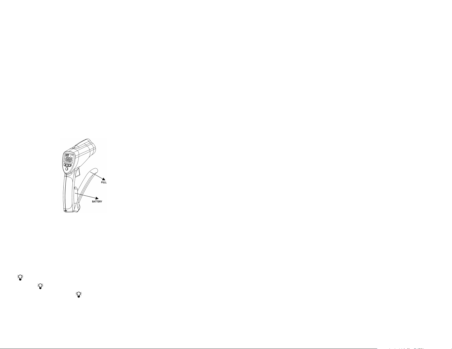
BATTERY REPLACEMENT
Erratic readings, faint readings, no display, or a
battery symbol appearing on the display are all
indications that the battery
must be replaced.
Locate the indentions
on either side of the
plastic case near the
trigger. Open the battery
compartment by pulling
the rubber portion of the
handle out and away from
the trigger. Pull hard, it
requires a good amount of
force to open the battery
compartment. Remove
the exhausted battery and replace it with a new
9-volt alkaline battery. Close the battery cover by
snapping it shut.
TRACEABLE
INFRARED
THERMOMETER
INSTRUCTIONS
© 2014 92-4484-40 Rev. 0 111914
®
GUN
 Loading...