

Page 1
O
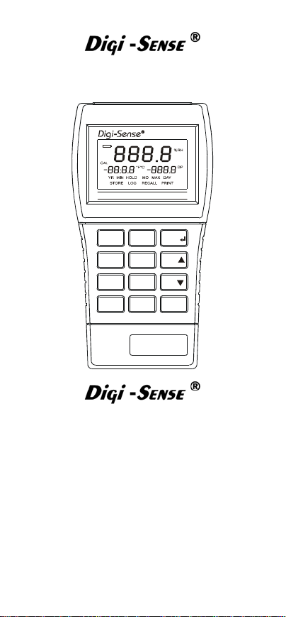
Humidity Data Logger
MODEL NO. 37003-02
HumidityLogR THER MOHYGROMETER
°C/°F
STORE
RECALL
CLEAR
ON/OFF
Cole-Parmer Instrument Co.
625 East Bunker Court
Vernon Hills, Illinois U.S.A. 60061-1844
(847) 549-7600
(847) 247-2929 (Fax)
800-323-4340
www.coleparmer.com
e-mail: techinfo@coleparmer.com
68X309918 Rev.0 01/04
LOG
PRINT
SETUP
Humidity
HOLD
MAX
MIN
CAL
IS
REGISTERED
9001
Page 2

Page 3

Table of Contents
INTRODUCTION ...........................................1
SAFETY PRECAUTIONS.............................. 2
SPECIFICATIONS......................................... 3
BATTERY INSTALLATION AND
REPLACEMENT............................................ 5
AC ADAPTER................................................ 6
CONNECTING THE PROBE......................... 6
QUICK SETUP ............................................10
RESET FACTORY DEFAULTS................... 11
COMPLETE SETUP PROCEDURE ............12
SELECTING LOWER DISPLAY MODE. 12
SHOW DEW POINT OR BLANK ........... 12
DISPLAY RESOLUTION........................ 13
FILTER RATE ........................................13
REAL-TIME CLOCK............................... 13
LOG SETUP........................................... 14
PRINT SETUP .......................................15
SELECTING INDIVIDUAL PARAMETERS
...............................................................16
OPERATING PROCEDURES ..................... 17
GENERAL ..............................................17
OPERATION ..........................................17
BASIC MEASUREMENTS .....................17
SELECTING THE TEMPERATURE
SCALE....................................................18
MAXIMUM READINGS ..........................18
Clearing a Maximum Reading ..........18
MINIMUM READINGS ...........................19
Clearing a Minimum Reading ...........19
HOLD FUNCTION.................................. 19
STORED READINGS ............................ 20
RECALL READINGS .............................20
CLEARING STORED OR LOGGED
READINGS.............................................21
LOGGING READINGS........................... 21
PRINTING ..............................................22
Testo Format for Normal Printing .....22
Testo Format for Log Dump.............. 23
Page 4

RS-232-C Format for Normal Printing
and Log Dump ..................................25
CALIBRATION............................................. 27
SINGLE-POINT CALIBRATION
PROCEDURES ......................................27
Humidity and Temperature Calibration
..........................................................27
Temperature Only Calibration........... 28
DUAL-POINT CALIBRATION
PROCEDURES ......................................29
Humidity and Temperature Calibration
..........................................................29
Temperature Only Calibration........... 31
FIELD CALIBRATION LOCKOUT AND
RE-ENABLE...........................................32
Lockout Procedure .................................32
Re-Enable Procedure............................. 32
MAINTENANCE AND TROUBLESHOOTING
.....................................................................33
BATTERIES ...........................................33
SERVICE................................................33
TROUBLESHOOTING.................................35
ACCESSORIES........................................... 36
Part Number ...........................................36
Calibration Salts .....................................36
Calibration Services ...............................36
WARRANTY ................................................37
PRODUCT RETURN ...................................37
TECHNICAL ASSISTANCE ........................37
Page 5

CERTIFICATE OF
CONFORMANCE
This thermohygrometer was calibrated
using equipment traceable to the National
Institute of Standards and Technology
(NIST).
Temperature measurements conform to
ITS-90.
The accuracy of the thermohygrometer at
the time of calibration was within
specifications stated in the operating
manual.
Model No.: ________________________
Serial Number: _____________________
Date placed in service:_______________
To purchase an NIST certificate of
traceability with test data and test date for
meter and probe, please contact your
ITS-90
dealer.
Page 6
INTRODUCTION
This versatile hand-held instrument provides
highly accurate relative humidity
measurements and temperature with
calculated dew point in Celsius or Fahrenheit.
This instrument covers the extended
measuring range of 0 to 100% RH, –40 to
+140°F (–40 to +60°C) temperature, and –130
to +140°F (–90 to +60°C) for dew point.
The instrument is designed for easy operation
and includes the following features:
Operator selection of temperature scale
Resolution of 0.1 (% RH, °F, °C, and DP)
LCD with three four-digit displays
Six-pin circular DIN connector input for
probe
Hold feature for temporarily retaining a
reading
Two-point field calibration capability for
humidity or temperature
- 1 -
Page 7

Low-battery warning
Stores or logs up to 1000 readings with
realtime markers
Scrolls through all stored readings
Displays MIN and MAX readings
Interfaces with optional Testo
printer or optional RS-232-C adapter
Prints temperature, humidity, dew point,
and time of reading
Detachable and interchangeable
humidity/temperature probe
Built-in tilt stand for easy hands-free
operation
infrared
SAFETY PRECAUTIONS
DO NOT USE OR
CAUTION
MICROWAVE OVENS OR ANY
ABNORMALLY HOT OR COLD AREAS.
CAUTION
INSTRUMENT. DEAD BATTERIES CAN
LEAK AND CAUSE DAMAGE TO UNIT.
STORE THIS
INSTRUMENT IN
WEAK BATTERIES
SHOULD NOT BE
LEFT IN THE
- 2 -
Page 8
SPECIFICATIONS
HUMIDITY/TEMPERATURE PROBE
Humidity
Temperature
Dew Point:
%
RH
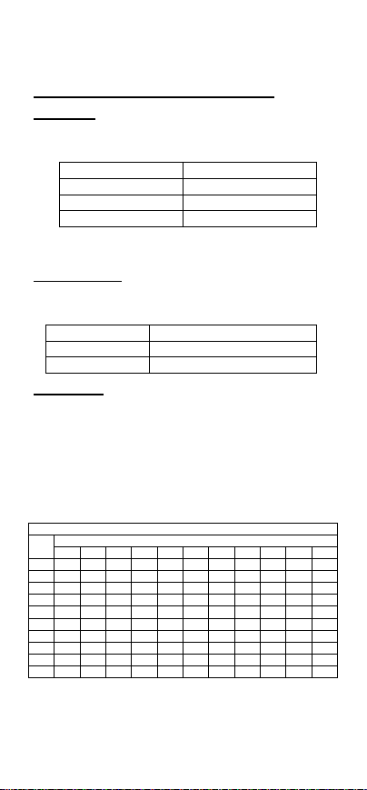
10 2.13 2.29 2.46 2.63 2.82 2.94 3.11 3.28 3.46 3.65 3.84
20 1.31 1.40 1.49 1.58 1.69 1.72 1.81 1.90 2.00 2.10 2.20
30 1.05 1.11 1.18 1.25 1.32 1.33 1.39 1.46 1.53 1.60 1.67
40 0.93 0.98 1.03 1.09 1.15 1.13 1.18 1.24 1.29 1.35 1.40
50 0.85 0.90 0.94 0.99 1.04 1.02 1.06 1.11 1.15 1.20 1.25
60 0.81 0.84 0.88 0.93 0.97 0.95 0.98 1.02 1.06 1.10 1.14
70 0.77 0.81 0.84 0.88 0.93 0.89 0.92 0.96 0.99 1.03 1.07
80 0.75 0.78 0.81 0.85 0.89 0.85 0.88 0.91 0.94 0.98 1.01
90 0.73 0.76 0.79 0.83 0.87 0.82 0.85 0.88 0.91 0.94 0.97
100 0.72 0.74 0.77 0.81 0.84 0.80 0.82 0.85 0.88 0.91 0.93
:
Type: Capacitive sensor
Range and Accuracy:
Range Accuracy
0% to 10% ±4% of reading
10% to 90% ±2% of reading
90% to 100% ±4% of reading
Response Time: 33% to 76% RH, still air at
25°C (77°F): 5 seconds
Type: Thermistor Element
Range and Accuracy:
Range Accuracy
–40 to +60°C ±(0.2% of reading ±0.5°C)
–40 to +140°F ±(0.2% of reading ±0.9°F)
Range: –90°C to +60°C (–130°F to +140°F)
Accuracy: Accuracy of the calculated dew point
depends on the accuracies of the
measured temperature and humidity values.
The following table reflects dew point
accuracy given sensor measurement
accuracies of ±0.5°C and ±2% RH.
Accuracy of Dew Point Temperature (±°C)
–40 –30 –20 –10 0 10 20 30 40 50 60
Temperature (°C)
- 3 -
Page 9

Dimensions (L × W × H):
21.3 cm × 3.2 cm × 4.4 cm
(8-3/8 in × 1-1/4 in × 1-3/4 in)
Insertion Diameter: 1.64 cm (0.65 in) at 3.30 cm
(1.3 in) depth
Compatible with Calibration Salts
(See ACCESSORIES on inside back cover.)
Cable Length: 91 cm (3 ft)
Weight: 114 g (4 oz)
Color: Black
LOGGER
Linearization:Temperature measurements
conform to ITS-90
Input Protection: 10 V rms
Display Update: 0.6 seconds per update
Connector: Circular 6-pin DIN
Dimensions (D × W × H):
3 cm × 8.4 cm × 15.8 cm
(1.2 in × 3.3 in × 6.2 in)
Weight with Batteries: 227 grams (8 ounces)
Ingress Protection: Meets IEC-60529 IP-54 for
dust- and water-resistant enclosures.
Compliance: For CE Mark:
EN61326-1/A1: 1998 (EU EMC Directive)
Battery
Size: Two AA, 1.5 V alkaline ANSI-L40,
IEC-LR6
Life: >200 hours continuous, typical
Display: LCD with 10 mm (0.4 in) high
characters main readout and 5 mm (0.2 in)
high characters secondary displays, 4 digits
each display plus various annunciators.
LOGGER OPERATING HUMIDITY /
TEMPERATURE RANGE:
Operating Temperature: 0 to 40°C (32 to 104°F)
Storage Temperature: –40 to 65°C (–40 to
149°F)
Humidity: 10% to 90% (non-condensing)
Altitude: Up to 2000 m (6560 ft)
- 4 -
Page 10
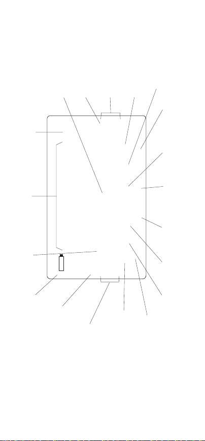
BATTERY INSTALLATION AND
REPLACEMENT
WEAK BATTERIES
CAUTION
INSTRUMENT. DEAD BATTERIES CAN
LEAK AND CAUSE DAMAGE TO UNIT.
When battery indicator illuminates, battery life
is approximately 8 to 10 hours. The battery
indicator starts flashing when battery life is
less than one hour. At that point, the battery
must be changed. If the battery charge
gets too low, the display blanks.
See SPECIFICATIONS for correct battery
type.
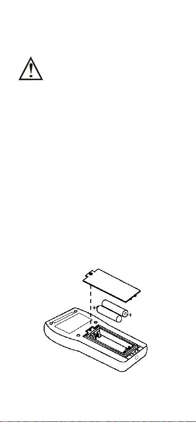
1) Before changing battery, turn instrument
off and disconnect probe.
2) Loosen screw and lift battery cover off
back of case.
3) Remove the two AA batteries.
4) Observe polarity, and insert two new
batteries.
5) Install cover and tighten screw.
SHOULD NOT BE
LEFT IN THE
- 5 -
Page 11
AC ADAPTER
An optional AC adapter can be used for power
to conserve batteries. The adapter is not a
charger and will not charge batteries. The
adapter connects to the bottom of the
instrument. When the adapter is connected,
the batteries are disconnected.
Refer to ACCESSORIES for adapter
information.
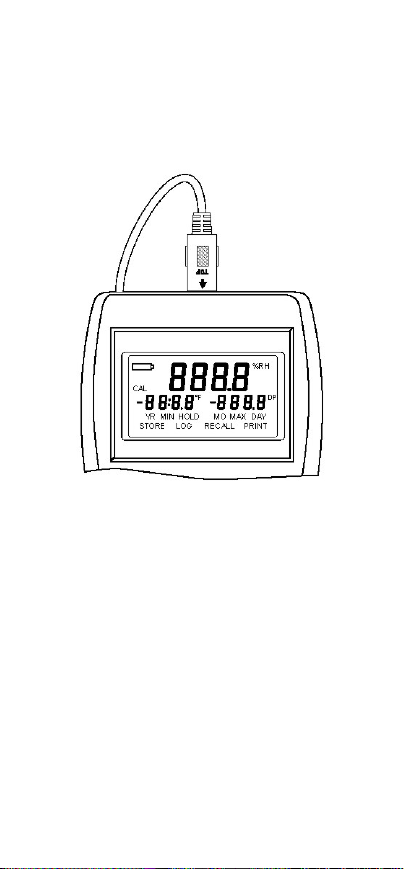
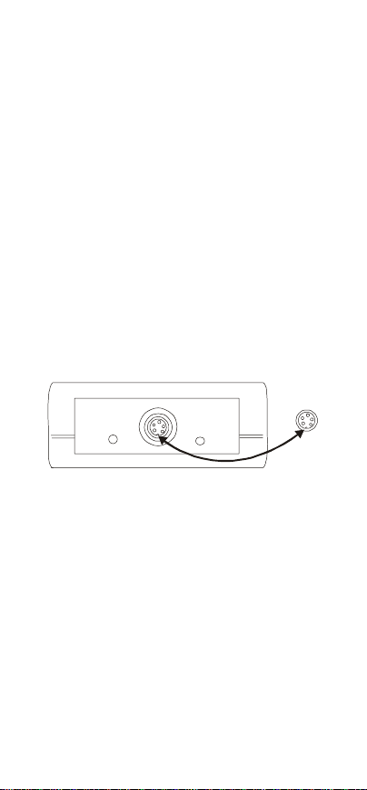
CONNECTING THE PROBE
A five-pin socket is located at the top of the
instrument. Align the slot locator in the plug of
the probe with the slot in the socket as shown
below. Insert the plug fully into the socket and
turn the locking ring clockwise to secure the
attachment.
- 6 -
Page 12
Maximum reading
displayed
Day being set
display
in SETUP
RECALL PRINTSTORE LOG
PRINT
Month
Recall
Log
operation
activated
being set in
SETUP
reading
activated
Temperature
display in °F or °C
%RH
Relative humidity
indicator
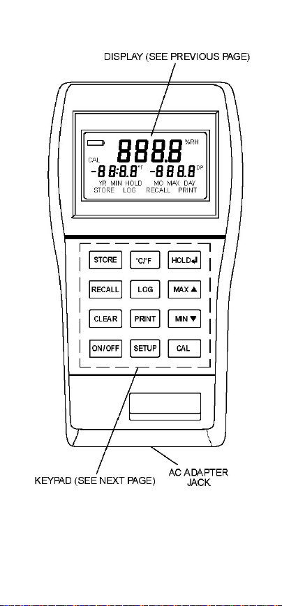
Main Display
Right-side secondary
Dew point
indicator
DP
°F°C
888.8
Tim e Dis play ed
Low battery
warning
Field calibration
is active
Left-side secondary
displ ay
- 7 -
YR MIN MAX DAYHOLD MO
-88:8.8 -888.8
CAL
Year being set
in SETUP
Reading
stored
Minimum
Display
Hold
reading
displayed
indicator
Page 13
- 8 -
Page 14
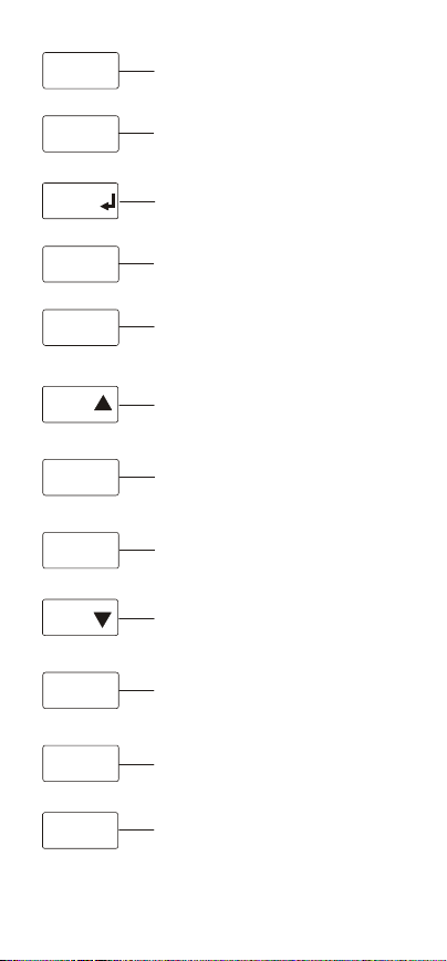
STORE
°C/°F
HOLD
Press to store current reading. Up to
1000 readings can b e stored with time
occurrence.
Press to select °C or °F temperature
scales.
Press to freeze reading in display.
Press again to unfreeze. (See
CALIBRATION
FOR FUNCTION. )
RECALL
LOG
MAX
CLEAR
PRINT
MIN
ON/OFF
SETUP
CAL
Press to enter recall mode.
Press to activate and deact ivate log
function.
Press to see briefly the maximum
reading since power up or clear. (See
CALIBRATION SETUP
RECALL for function.
Press to see initiate clear action. CAL,
MAX, MIN, STORE, PRINT, and LOG
are prompted to complete.
Press to activate and deact ivate
infrared output.
Press to see briefly the minimum
reading since p ower up to clear. (See
CALIBRATION ETUP
RECALL
Press to power up or turn off.
Press to select display characteristics,
dew point, scale, resolution, filter rate,
to set the real-time clock, and access
to LOG and PRINT submenus.
Press to enter field calib ration mode.
(See .)
, , and
, S , and
for x function.
CALIBRATION
- 9 -
Page 15

QUICK SETUP
NOTE
Review SAFETY PRECAUTIONS.
1) Install batteries.
2) Connect probe.
3) Press ON/OFF. The instrument performs
a self-test and all display digits and
indicators, as shown below, remain on for
approximately one second.
%RH
888.8
CAL
°F°C
DP
-88:8.8 -888.8
YR MIN MAX DAYHOLD MO
RECALL PRINTSTORE LOG
The time and date remain on for about three
seconds.
10:08 1028
DAYMO
- 10 -
Page 16

NOTE
If the probe has not been connected to the
instrument, “OPEN” appears in the display.
“OPEN” also appears if the probe is not
functioning. No measurements can be made
while this message is displayed.
%RH
Ope
°F
4) Press SETUP to enter the setup
sequence.
5) Use MAX▲ or MIN▼ to make and enter
selections. Press HOLD to accept the
value and go to the next step.
RESET FACTORY DEFAULTS
With the instrument off, press and hold
CLEAR and SETUP, then press and release
ON/OFF.
Hold CLEAR and SETUP until CLr is
displayed, then release the two buttons. Press
any key to continue.
DP
- 11 -
Page 17

COMPLETE SETUP PROCEDURE
The setup function scrolls through a series of
steps for selecting resolution, filter rate,
setting the real-time clock, and accessing the
LOG and the PRINT sub-menus. Either the
complete setup can be run as described
below, or the setup can be terminated at any
step. The LOG and PRINT sub-menus can be
accessed without going through the complete
setup.
NOTE
Settings selected in the Setup procedure
are stored in memory and remain even
after power is turned off or while batteries
are being replaced.
Press SETUP. The lower left display flashes
OFF, the time of day or the selected
temperature unit.
Display Options Factory
Lower
Display
Dew Point On/Off On
Resolution 0.1/1.0 0.1
Filter Update
Rate
Temp/Time/Off Temp (°F)
Off/Low/High Off
SELECTING LOWER DISPLAY MODE
Press MAX▲ or MIN▼ to toggle the lower
display to show the time of day, show
minimum and maximum temperature values,
or turn off. Press HOLD to accept the setting
and to advance to the next step.
Default
SHOW DEW POINT OR BLANK
Press MAX▲ or MIN▼ to toggle the Dew
Point display between on and off. Press
HOLD to accept the setting and to advance to
the next step.
- 12 -
Page 18

DISPLAY RESOLUTION
There are two choices for display resolution.
The default is 0.1 resolution, at which the
instrument automatically ranges between 0.1
and 1 as required. The other option is 1
resolution. When set to 1, the display remains
in this resolution for all measurements.
When 0.1 resolution is selected, a decimal
point appears in the numerical displays. When
1 resolution is selected, no decimal point is
present.
The upper display shows a flashing 0.1 or 1.
Press MAX▲ or MIN▼ to change resolution,
then press HOLD to accept the setting and to
advance to the next step.
FILTER RATE
The filter rate can be set to OFF, Lo or Hi.
This rate is changed to smooth out
fluctuations in the readings. Normally, the filter
rate is set to OFF. If readings are unstable, try
changing to Lo or Hi.
The lower left display shows FILt and the
upper display flashes either OFF, Lo or Hi.
Use MAX▲ or MIN▼ to change the filter rate,
and then press HOLD to accept the setting
and to advance to the next step.
REAL-TIME CLOCK
1) When setting the real-time clock, the right
two digits in the lower left display flash.
2) Use the MAX▲ or MIN▼ to adjust the
flashing digits to the desired minute
setting.
3) Press to store the minutes and advance
to the hours setting.
- 13 -
Page 19

NOTE
Hours are set in the 24-hour time system.
Therefore, time after 12:59 PM requires
12 to be added to the time. For example,
3:00 PM is (3+12) = 15:00 hours.
4) The left two digits in the lower left display
flash. Use MAX▲ or MIN▼ to adjust the
flashing digits to the desired hour setting.
5) Press HOLD to store the hours and to
advance to the month setting.
6) The MO annunciator displays and the
right two digits in the lower right display
flash. Use MAX▲ or MIN▼ to adjust the
flashing digits to the desired month
setting (1 to 12).
7) Press HOLD to store the month and to
advance to the day setting.
8) The DAY annunciator displays and the
right two digits in the lower right display
flash. Use MAX▲ or MIN▼ to adjust the
flashing digits to the desired day setting
(1 to 31).
9) Press HOLD to store the day and to
advance to the year setting.
10) The YR annunciator displays and the
two digits in the lower left display flash.
Use MAX▲ or MIN▼ to adjust the
flashing digits to the desired year setting
(2000 to 2063).
11) Press HOLD to store the year. To set up
the log or print functions, proceed to the
following paragraphs.
LOG SETUP
The LOG sub-menu is used to set the time
intervals between the logged readings. The
time can be set from one second to 60
minutes. Once the log sub-menu is set up,
logging can be toggled ON or OFF by
- 14 -
Page 20

pressing LOG. When logging is turned ON, it
continues until turned OFF or until 1000 logs
have occurred at the entered rate. The first
1000 logs are retained.
1) Press LOG anytime during SETUP. The
LOG annunciator displays along with the
currently set time interval (default is one
second). The two right digits,
representing seconds, flash.
2) Use MAX▲ or MIN▼ to adjust the
“seconds” as desired. Press HOLD to
store the setting and to advance to the
“minutes” setting.
3) Use MAX▲ or MIN▼ to adjust the
“minutes” as desired. Press HOLD to
store the setting and to complete the
Logging setup.
PRINT SETUP
The PRINT sub-menu is used to set the time
intervals between the readings being sent to
the printer. The default rate is once every four
seconds. The time can be set from four
seconds to 60 minutes. Once the print submenu is set up, printing can be toggled ON or
OFF by pressing PRINT. In addition, the data
rate for the infrared RS-232-C output can be
set.
1) Anytime PRINT is pressed during SETUP,
the PRINT annunciator displays along
with the currently set time interval
(default is four seconds). The two right
digits, representing seconds, flash.
2) Use MAX▲ or MIN▼ to adjust the
“seconds” as desired. Press HOLD to
store the setting and to advance to the
“minutes” setting.
3) Use MAX▲ or MIN▼ to adjust the
“minutes” as desired. Press HOLD to
- 15 -
Page 21

store the setting and to proceed to the
data output rate.
4) Use MAX▲ or MIN▼ to scroll through
the available data output rates of HP, 300,
600, 1200 or 2400 (default). Use HP for
the Testo infrared printer. The data
output rates of 300, 600, 1200 and 2400
are for use with the optional infrared to
RS-232-C adapter. Press HOLD to store
the setting and to end the setup.
SELECTING INDIVIDUAL PARAMETERS
The resolution, filter update rate and real-time
clock can be set individually without
performing the complete setup. First press
SETUP, then repeatedly press HOLD until the
desired function is displayed. Use MAX▲ or
MIN▼ to change the function and press
HOLD to store the setting.
- 16 -
Page 22

OPERATING PROCEDURES
GENERAL
Reaching temperature equilibrium is essential
when measuring humidity in calibration. Even
a small temperature difference between the
sensor and the measured object can cause an
error. For example, at a temperature of +20°C
(+68°F) with an RH of 50%, a difference of
±1°C between the sensor and the measured
object results in an error of ±3% RH. For
humidity of 90% RH, the resulting error is
±5.4% RH.
A greater error results when there is high
humidity and the sensor is warmer or colder
than its surroundings. A difference in
temperature of a few degrees can cause
water to condense on the sensor’s surface.
Evaporation can take hours in an unventilated
space; good ventilation accelerates
evaporation. The humidity sensor resumes
normal function as the water evaporates.
Contaminated condensed water may shorten
the life span of the sensor and change its
calibration.
OPERATION
The unit always powers up with the upper
display showing humidity. If a probe is not
connected at power up, the upper display
indicates OPEN. For optimum operation, allow
about one minute for ambient temperature
stabilization. If the unit has been stored at an
extreme ambient condition, more time may be
needed.
BASIC MEASUREMENTS
Check that the instrument is turned on, the
probe is connected, and the desired resolution
- 17 -
Page 23

(0.1° or 1°) and temperature (°C or °F) scales
are selected. If the display is set to factory
defaults, the upper display shows relative
humidity and the lower display shows
temperature and dew point. The lower display
may also be set to show time or be off, and
the dew point may be set not to display (off).
Refer to SELECTING THE LOWER DISPLAY
MODE for displaying temperature and dew
point.
SELECTING THE TEMPERATURE SCALE
Use °C/°F for selection of the Celsius or
Fahrenheit scale. The last selection is
retained in memory even if the instrument is
turned off.
MAXIMUM READINGS
The maximum reading function displays the
maximum reading since power up or since the
last time the clear function was used. The
maximum reading function is ideal for
monitoring unattended operations while
continually displaying every temperature,
humidity, and dew point change that occurs.
The maximum and minimum values are
sensed and automatically stored until you are
ready to observe the reading.
Do not turn off the instrument when a
maximum or minimum temperature, humidity,
or dew point value may be needed; MAX/MIN
memory contents are lost when the instrument
is turned off.
Clearing a Maximum Reading
Press CLEAR, then press MAX▲. The
maximum memory is cleared.
- 18 -
Page 24

MINIMUM READINGS
The minimum reading function displays the
minimum reading since power up or since the
last time the clear function was used. While
continually displaying every temperature,
humidity, and dew point change that occurs,
the maximum and minimum values are
sensed and automatically stored until you are
ready to observe the reading.
Do not turn off the instrument when a
maximum or minimum temperature, humidity,
or dew point value may be needed; MAX/MIN
memory contents are lost when the instrument
is turned off.
Clearing a Minimum Reading
Press CLEAR then MIN▼. The minimum
memory is cleared.
HOLD FUNCTION
Press HOLD to retain the reading on the
display. Press HOLD again for normal
operation.
Maximum Hold
Press MAX▲ then press HOLD. Press HOLD
again to turn off the HOLD function and return
to normal operation.
To clear the maximum readings, press
CLEAR, then MAX▲.
Minimum Hold
Press MIN▲ then press HOLD. Press HOLD
again to turn off the HOLD function and return
to normal operation.
To clear the minimum readings, press CLEAR,
then MIN▼.
- 19 -
Page 25

STORED READINGS
The store function allows you to store up to
1000 readings. Each reading is logged with a
storage location number and the time of
occurrence.
To store readings, proceed as follows:
1) Momentarily press STORE. The present
humidity, temperature, and dew point are
stored. The STORE annunciator displays
and the upper main display momentarily
shows the storage location number.
After three seconds, the storage number
is replaced with a humidity and
temperature reading, and the STORE
annunciator remains on to indicate a
humidity and temperature reading has
been stored. STORE may be pressed as
frequently as once per second.
2) Repeat step 1 for all the points to be
recorded, up to a maximum of 1000.
Each time STORE is pressed, the new
reading is stored and the upper main
display shows the storage location
number for about three seconds.
3) After 1000 stored readings, the next time
STORE is pressed the main display
indicates FULL.
RECALL READINGS
This function allows the stored readings, the
reading sequence number, and the Time/Date
of the readings to be recalled. RECALL shows
each stored reading individually. When
individual readings are recalled, you can
toggle between the reading and the sequence
number of the reading.
To recall readings:
- 20 -
Page 26

1) Momentarily press RECALL. The time
and date are displayed on the lower
displays and the stored sequence
number is displayed on the main display.
The STORE and RECALL annunciators
are shown.
2) To step through the readings, press
MAX▲ or MIN▼. Each key press
advances to the next reading in
sequence. Hold down MAX▲ or MIN▼
to advance at an increasing rate through
the readings. To increment or decrement
by 100, proceed as follows:
To increment, hold down MAX▲ then
press the MIN▼ key.
To decrement, hold down MIN▼ then
press the MAX▲ key.
3) To toggle between the readings and the
reading sequence number, press
RECALL again.
4) To return to normal operation, press any
key other than ON/OFF, MAX▲, MIN▼
or RECALL.
CLEARING STORED OR LOGGED
READINGS
Press CLEAR, then either STORE or LOG.
Regardless of which key is pressed, the
stored and logged readings in memory are
cleared.
LOGGING READINGS
The Logging function is controlled by the LOG
key. Prior to logging readings, it is necessary
to set up the time interval between readings
(see LOG SETUP) in COMPLETE SETUP
PROCEDURE.
The time between readings can be set toany
value from one second to 60 minutes. Logging
- 21 -
Page 27

is initiated by pressing LOG and continues at
the programmed rate until LOG is pressed
again or 1000 logs have occurred. If 1000
logs have occurred, the display shows FULL.
The STORE function can be used during
logging to insert additional measurements by
pressing STORE.
PRINTING
Printing can output real-time readings or
stored readings. The output is sent to the
infrared (IR) printer output located at the top
of the instrument. The printer output default
time period is once every three seconds. This
time can be set to any value between three
seconds and 60 minutes (see PRINT SETUP)
in COMPLETE SETUP PROCEDURE.
The following sample printouts show the RS232-C format and the Testo (IR) printer in
normal and log dump print modes. Note that
in log dump print mode the first line specifies
the total number of readings.
The print function is controlled by the PRINT
key.
Testo Printer Format for Normal Printing
The information sent as an output to the
printer is based on the display settings.
Several examples are shown. A new heading
appears when the date changes or a new
print is started.
NOTE
– – – – in the printout indicates an over range
condition.
- 22 -
Page 28

Both Lower Displays On:
03/02/01 % RH °F
10:37:26 28.1 74.9
10:37:31 28.1 74.9
10:37:35 28.1 74.9
10:37:39 28.0 74.8
10:37:43 28.0 74.8
10:37:47 27.9 74.8
DP: 39.7
DP: 39.7
DP: 39.7
DP: 39.5
DP: 39.5
DP: 39.4
Dew Point Off:
3/02/01 % RH °F
10:38:03 28.0 74.8
10:38:07 28.1 74.8
10:38:11 28.0 74.8
10:38:15 27.9 74.8
10:38:19 27.9 74.8
10:38:23 27.9 74.8
10:38:27 27.9 74.8
Dew Point and Degrees Off:
03/02/01 % RH
10:39:17 27.8
10:39:21 27.7
10:39:25 27.7
10:39:29 27.7
10:39:33 27.8
Testo Printer Format for Log Dump
The information sent as an output to the
printer is based on the display settings.
Several examples are shown. A new heading
appears when the date changes.
NOTE
– – – – in the printout indicates an over
range condition.
- 23 -
Page 29

Both Lower Displays On:
TOTAL READINGS: 20
03/02/01 % RH °F
10:43:52 27.7 75.0
DP: 39.4
10:43:53 27.7 75.0
DP: 39.4
10:43:54 27.7 75.0
DP: 39.4
10:43:55 27.8 75.0
DP: 39.5
10:43:56 27.8 75.0
DP: 39.5
10:43:57 27.8 75.0
DP: 39.5
10:43:58 27.8 75.0
DP: 39.5
10:43:59 27.9 75.0
DP: 39.6
10:44:00 27.9 75.0
DP: 39.6
10:44:01 27.9 75.0
DP: 39.6
10:44:02 27.9 75.0
DP: 39.6
Dew Point Off:
TOTAL READINGS: 20
03/02/01 % RH °F
10:43:52 27.7 75.0
10:43:53 27.7 75.0
10:43:54 27.7 75.0
10:43:55 27.8 75.0
10:43:56 27.8 75.0
10:43:57 27.8 75.0
10:43:58 27.8 75.0
NOTE
Printing 1000 stored sets of readings could
take an hour depending on printer model.
- 24 -
Page 30

RS-232-C Format for Normal Printing and
Log Dump
NOTE
– – – – in the printout indicates an over
range condition.
“DATE”,“TIME”,“% RH”,“DEGREES F”,“DEWPT F”
03/02/01, 10:43:52, 27.7, 75.0, 39.4
,10:43:53, 27.7, 75.0, 39.4
,10:43:54, 27.7, 75.0, 39.4
,10:43:55, 27.8, 75.0, 39.5
,10:43:56, 27.8, 75.0, 39.5
,10:43:57, 27.8, 75.0, 39.5
,10:43:58, 27.8, 75.0, 39.5
The print function is controlled by the PRINT
key.
Proceed as follows:
1) Perform the PRINT Setup procedure to
set the desired print rate.
2) Check that the IR printer input is properly
aligned with the IR output at the top of
the instrument.
- 25 -
Page 31

Printer output occurs in real-time when
the instrument is operating in normal
mode. When the instrument is in RECALL
mode, printing of the stored information
occurs.
3) Press PRINT to start printing. Printing
continues at the programmed print rate
until PRINT is pressed again, or if stored
data is being printed and all data has
been transferred to the printer. When
printing stored data, the temperature,
humidity, dew point, and times of
occurrence are output.
- 26 -
Page 32

CALIBRATION
The calibration function allows both singlepoint and dual-point calibration of the
instrument. Single-point calibrates the offset
only. Dual-point calibrates the offset first then
calibrates the slope.
It is not necessary to perform a field
calibration to obtain specified accuracies. Use
the field calibration feature to improve
instrument/probe accuracy or to compensate
for probe calibration drift.
The instrument has a memory retention
capability to hold calibration values even while
the power is off or the batteries are removed.
When you restart, there is no need to
recalibrate.
SINGLE-POINT CALIBRATION
PROCEDURES
Humidity and Temperature Calibration
1) Momentarily press CAL to enter the
CALIBRATION mode. The CAL
annunciator flashes. The relative
humidity is displayed on the main display
and “Lo” is displayed on the lower left
display. “Lo” signifies the offset point.
2) Insert the probe into controlled humidity
at the calibration point.
3) Allow the reading to stabilize. If the
displayed humidity is higher or lower than
the reference humidity, use MAX▲ to
increase the displayed reading or MIN▼
to decrease the displayed reading until
the reference humidity is displayed.
MIN▼ or MAX▲ must be pressed at
least once. The CAL annunciator flashes
during this procedure.
- 27 -
Page 33

4) Press CAL. The main display shows
temperature.
5) Insert the probe into controlled
temperature at the calibration point.
6) Allow the reading to stabilize. If the
displayed temperature is higher or lower
than the reference temperature, use
MAX▲ to increase the displayed reading
or MIN▼ to decrease the displayed
reading until the reference temperature is
displayed. MIN▼ or MAX▲ must be
pressed at least once. The CAL
annunciator flashes during this procedure.
7) Press CAL to store the calibration.
Temperature Only Calibration
1) Momentarily press CAL to enter the
CALIBRATION mode. The CAL
annunciator flashes. The relative
humidity is displayed on the main display
and LO is displayed on the lower left
display signifying the offset point.
2) Press CAL again. The main display
changes to temperature.
3) Insert the probe into controlled
temperature at the calibration point.
4) Allow the reading to stabilize. If the
displayed temperature is higher or lower
than the reference temperature, use
MAX▲ to increase the displayed reading
or MIN▼ to decrease the displayed
reading until the reference temperature is
displayed. MIN▼ or MAX▲ must be
pressed at least once. The CAL
annunciator flashes during this procedure.
5) Press CAL to store the calibration.
- 28 -
Page 34

DUAL-POINT CALIBRATION
PROCEDURES
This calibration function provides both for
offset and slope field calibrations. For proper
calibration, the following conditions must be
observed:
The slope point must be a higher
temperature or humidity than the offset
point.
The difference must be at least 20°C (36°F)
or 20% RH.
Use two points based on the expected high
and low humidity and temperatures.
Humidity and temperatures measured
outside of these limits may no longer meet
specifications.
Resolution is based on the selected
display resolution.
Humidity and Temperature Calibration
1) Humidity Offset Calibration:
Momentarily press CAL to enter the
CALIBRATION mode. The CAL
annunciator flashes. The relative
humidity is displayed on the main display
and “Lo” is displayed on the lower left
display. “Lo” signifies the offset point.
2) Insert the probe into controlled humidity
at the lower calibration point.
3) Allow the reading to stabilize. If the
displayed humidity and temperature are
higher or lower than the reference
temperature, use MAX▲ to increase the
displayed reading or MIN▼ to decrease
the displayed reading until the reference
humidity and temperature are displayed.
MIN▼ or MAX▲ must be pressed at least
once. The CAL annunciator flashes during
this procedure.
- 29 -
Page 35

4) Press HOLD to store the humidity offset
calibration and advance to the slope
calibration.
5) Humidity Slope Calibration: Place the
probe at the higher reference humidity
and temperature.
6) Allow the reading to stabilize. If the
displayed humidity and temperature are
higher or lower than the reference
humidity and temperature, use MAX▲ to
increase the displayed reading or MIN▼
to decrease the displayed reading until
the reference temperature is displayed.
MIN▼ or MAX▲ must be pressed at
least once. The CAL annunciator flashes
during this procedure.
7) Press HOLD to store the humidity slope
calibration and proceed to the
temperature calibration.
8) Temperature Offset Calibration: Insert
the probe into controlled temperature at
the lower calibration point.
9) Allow the reading to stabilize. If the
displayed temperature is higher or lower
than the reference temperature, use
MAX▲ to increase the displayed reading
or MIN▼ to decrease the displayed
reading until the reference temperature is
displayed. MIN▼ or MAX▲ must be
pressed at least once. The CAL
annunciator flashes during this procedure.
10) Press HOLD to store the temperature
offset calibration and advance to the
slope calibration. To return to normal
operation, press any key except CAL or
HOLD.
11) Temperature Slope Calibration: Place
the probe at the higher reference
temperature.
- 30 -
Page 36

12) Allow the reading to stabilize. If the
displayed temperature is higher or lower
than the reference temperature, use
MAX▲ to increase the displayed reading
or MIN▼ to decrease the displayed
reading until the reference temperature is
displayed. MIN▼ or MAX▲ must be
pressed at least once. The CAL
annunciator flashes during this procedure.
13) Press HOLD to store the temperature
calibration.
Temperature Only Calibration
1) Offset Calibration: Momentarily press
CAL to enter the CALIBRATION mode.
The CAL annunciator flashes. The
relative humidity is displayed on the main
display and “Lo” is displayed on the lower
left display. “Lo” signifies the offset point.
2) Press CAL again. The main display
changes to temperature.
3) Insert the probe into controlled
temperature at the lower calibration point.
4) Allow the reading to stabilize. If the
displayed temperature is higher or lower
than the reference temperature, use
MAX▲ to increase the displayed reading
or MIN▼ to decrease the displayed
reading until the reference temperature is
displayed. MIN▼ or MAX▲ must be
pressed at least once. The CAL
annunciator flashes during this procedure.
5) Press HOLD to store the temperature
offset calibration and advance to the
slope calibration. To return to normal
operation, press any key except CAL or
HOLD.
6) Slope Calibration: Place the probe at
the higher reference temperature.
- 31 -
Page 37

7) Allow the reading to stabilize. If the
displayed temperature is higher or lower
than the reference temperature, use
MAX▲ to increase the displayed reading
or MIN▼ to decrease the displayed
reading until the reference temperature is
displayed. MIN▼ or MAX▲ must be
pressed at least once. The CAL
annunciator flashes during this procedure.
8) Press HOLD to store the temperature
slope calibration.
Clearing Cal Point: Press CLEAR, then CAL.
The instrument reverts to the factory
calibration with no offset or slope
compensation.
FIELD CALIBRATION LOCKOUT AND REENABLE
The calibration lockout feature prevents any
field calibration changes. The lockout remains
in effect until a lockout re-enable has been
performed. Use the following procedures to
lockout or re-enable the field calibration
operation.
Lockout Procedure
1) Turn off the instrument.
2) Simultaneously press and hold CAL and
CLEAR, and momentarily press ON/OFF.
Continue to hold CAL and CLEAR for at
least five seconds.
Re-Enable Procedure
1) Turn off the instrument.
2) Simultaneously press and hold CAL and
HOLD, and momentarily press ON/OFF.
Continue to hold CAL and HOLD until
the display blanks.
- 32 -
Page 38

MAINTENANCE AND
TROUBLESHOOTING
Properly used, the instrument should maintain
calibration indefinitely and not require service
other than occasional cleaning of the housing
and changing of the batteries.
Do not clean with abrasives or solvents. Use
mild detergents; never immerse nor use
excessive fluid.
BATTERIES
If there is no display when the instrument is
turned on, check the condition of the two AA
batteries. Check that the battery terminals are
clean and batteries are properly installed. If
replacement is necessary, refer to BATTERY
INSTALLATION AND REPLACEMENT for
the replacement procedure.
The real-time clock keeps time for up to one
minute with the batteries removed. To
minimize the need for resetting the clock,
either remove and replace one battery at a
time, or connect the AC adapter while
changing the batteries. All stored/logged
readings are retained until cleared, even if the
batteries are removed for long periods.
SERVICE
There are no internal adjustments or user
replaceable parts.
If “Err” followed by the numbers “1” through 9”
is displayed (see example below), return unit
for service. “Err” alone may be displayed
during improper field calibration.
- 33 -
Page 39

NOTE
The serial number label is located inside the
battery compartment.
- 34 -
Page 40

TROUBLESHOOTING
The following chart lists the most probable
faults. There are no internal adjustments or
user replaceable parts. If this does not solve
the problem, refer service to your dealer.
FAULT ACTION
No display when
turned on
Display shows
- - - -
Display shows
“OPEN”
Display shows
“Err”
If “Err 1” through: Err 9” remains on the
display, return instrument for service.
Check condition of batteries.
Check that batteries are
inserted properly.
Check operation using AC
adapter.
Out of range indication.
Open probe connection
If displayed at any time other
than during field calibration,
return instrument for service.
- 35 -
Page 41

ACCESSORIES
Part Number
37003-02 Humidity logger
10374-50 Infrared printer, includes one roll
10374-52 Replacement printer paper, pack
91100-85 RS-232-C interface connects to
37003-62 Replacement Relative Humidity
91100-52 AC Adapter for
91100-55 AC Adapter for
08520-05 Carrying case for meter
Calibration Salts
37450-10 Calibration Kit with 11.3% and
of paper and four AA batteries
of six rolls
computer’s 9-pin serial port for
easy uploading of data. Use with
most popular RS-232-C
programs.
probe
Thermohygrometer, 115 VAC
Thermohygrometer, 230 VAC
75.3% RH salts
Calibration Services
17030-20 NIST-traceable calibration with
test data after calibration at 30%,
60%, and 80% RH; 30°C (86°F)
- 36 -
Page 42

WARRANTY
The Manufacturer warrants this product to be
free from significant deviations from published
specifications.
If repair or adjustment is necessary within the
warranty period, the problem will be corrected
at no charge if it is not due to misuse or abuse
on your part as determined by the
Manufacturer.
Repair costs outside the warranty period, or
those resulting from product misuse or abuse,
may be invoiced to you.
This product comes with a 3-year meter
warranty and 6-month Humidity /
Temperature probe warranty.
PRODUCT RETURN
To limit charges and delays, contact the seller
or Manufacturer for authorization and shipping
instructions before returning the product,
either within or outside of the warranty period.
When returning the product, please state the
reason for the return. For your protection,
pack the product carefully and insure it
against possible damage or loss. Any
damages resulting from improper packaging
are your responsibility.
TECHNICAL ASSISTANCE
If you have any questions about the use of
this product, contact the Manufacturer or
authorized seller.
Trademarks bearing the ® symbol in this publication are
registered in the U.S. and in other countries.
- 37 -
Page 43

-
Page 44

For more information on Cole-Parmer products, contact
your nearest distributor or visit our website listed below:
Cole-Parmer
Instrument Co.
625 East Bunker Court
Distributed by:
Vernon Hills, Illinois U.S.A.
60061-1844
(847) 549-7600
(847) 247-2929 (Fax)
800-323-4340
www.coleparmer.com
e-mail:
techinfo@coleparmer.com
 Loading...