

Page 1
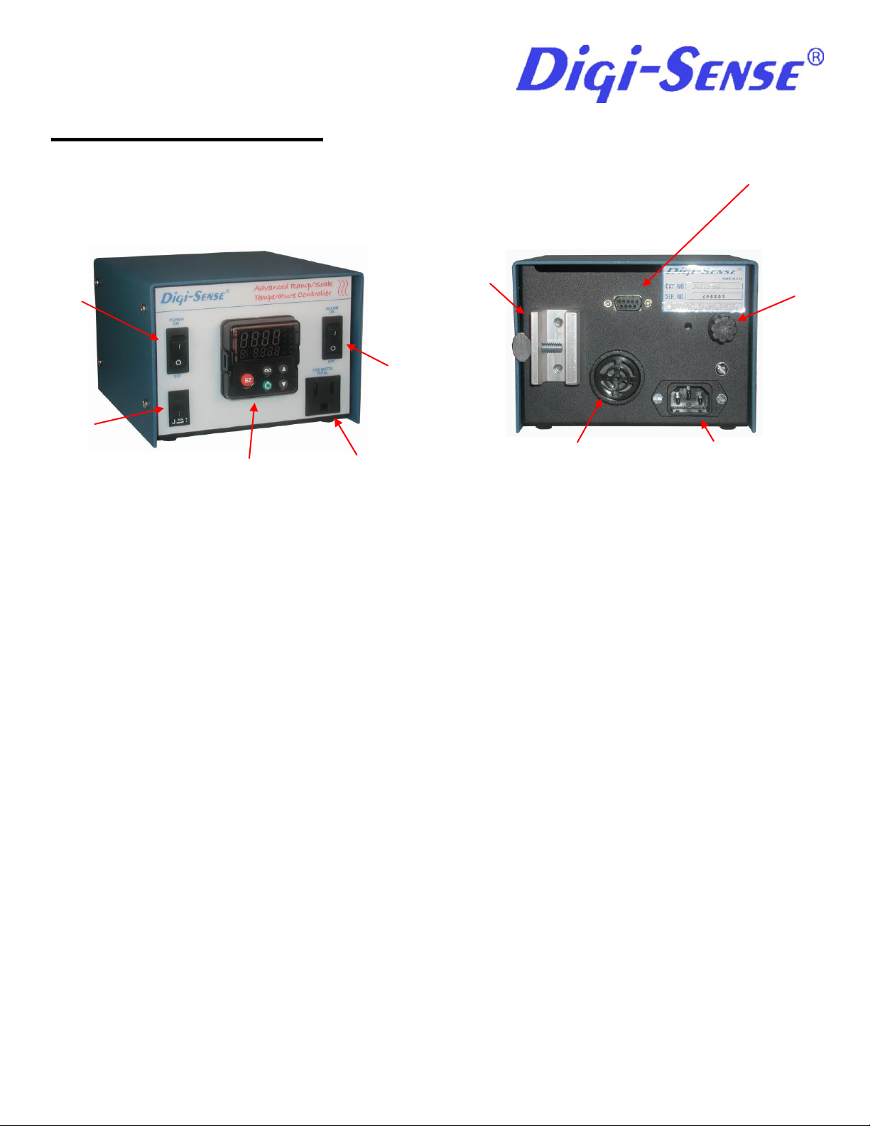
Power
Inlet
Grid
Support
Load
Fuse
Load
Outlet
Sensor
Input
ON/OFF
Switch
Digital
Control
Module
Alarm
RS-232
Port
ON/OFF
Alarm
Switch
Operation Manual
Instruction Notes for 3622566, 3622567, 3622568, 3622569
Figure 1 Figure 2
General Description
If your heating process requires several steps, this is the control for you. The Ramp/Soak feature of this control allows up
to a 40-step profile, which can be configured from the provided software. You can profile Temperature, Time, Hold, Soak
and End steps to create the ideal profile for your process. The built in adaptive control technology provides even tighter
control for these demanding applications. Several input types are available. This unit comes with 6’ detachable power
cord, communication port, audible alarm function and grid support bracket, which is ideal for fume hood mounting to
maximize bench space.
This control is a microprocessor-based, digital indicating, automatic temperature control with a single input and a single
output. It features an auto-tuning function that allows automatic setting of control parameters with a minimum of user input
required. This family of control accepts a type "J", “K”, “T” thermocouples or RTD input depending on the model ordered.
The control automatically sets the PID parameters through a "learning" sequence in the auto-tuning mode. PID
parameters include proportional band, reset/integral and rate/derivative. User-friendly features include automatic LED
indicators to aid in monitoring and setup, as well as dual LED displays for process temperature and set point indication.
This control automatically stores all information in a non-volatile memory.,
Control Features
1. On/Off power switch.
2. On/Off alarm switch.
3. 12-amp output.
4. Control PID with Auto-tune algorithm, solid state relay
5. Circuit protection (fuse)
6. Low profile housing.
12/10 1 Rev.1
Page 2
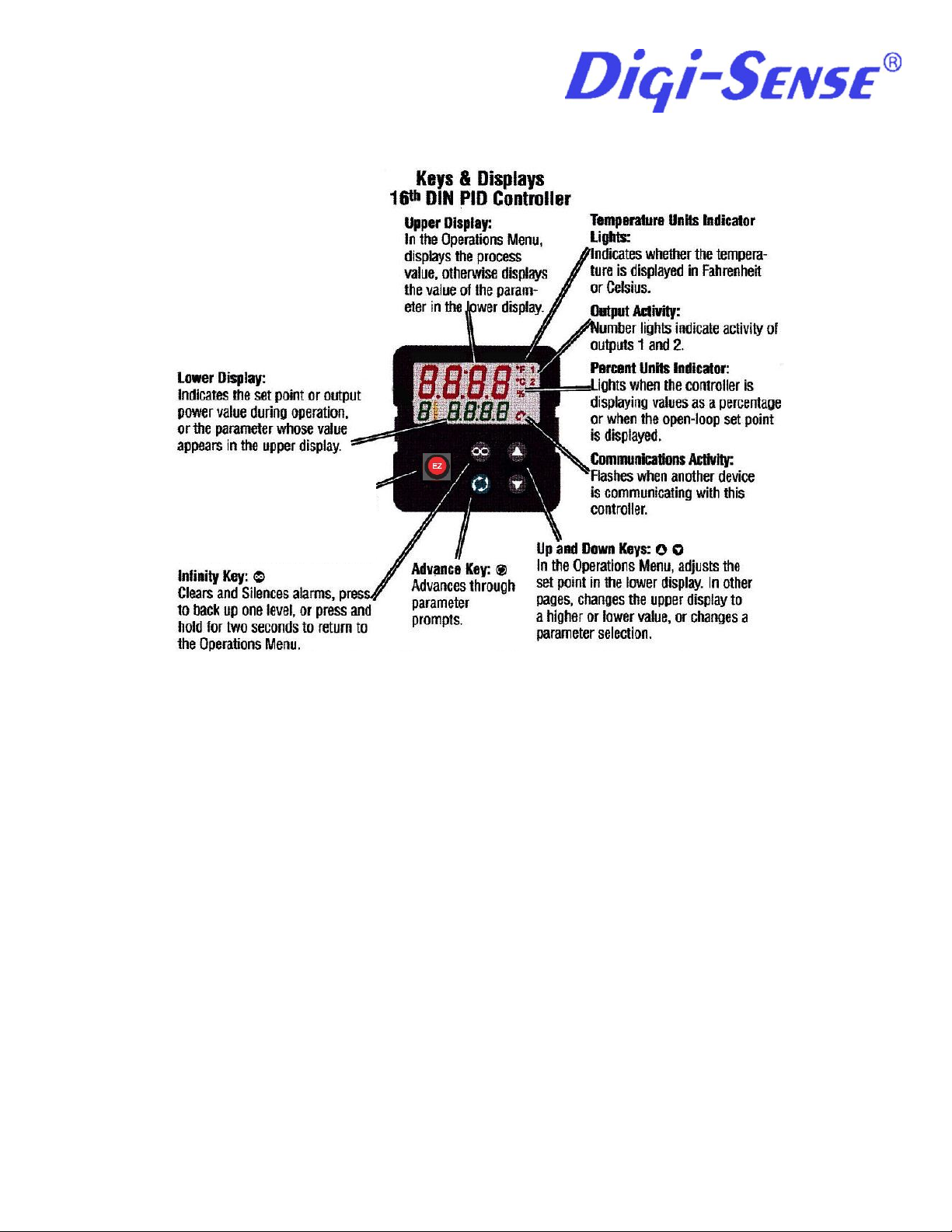
EZ button – User defined
How to Setup and Operate
First, connect the heater load and the sensor to the load and sensor receptacles on the front panel. Next, plug the control
line cord into an appropriate 3-wire grounded power receptacle. Push the power switch to the "ON" position. Wait five
seconds for the control unit to energize.
The control is shipped from the factory with the display reading in degrees C. If a display in degrees F is desirable, press
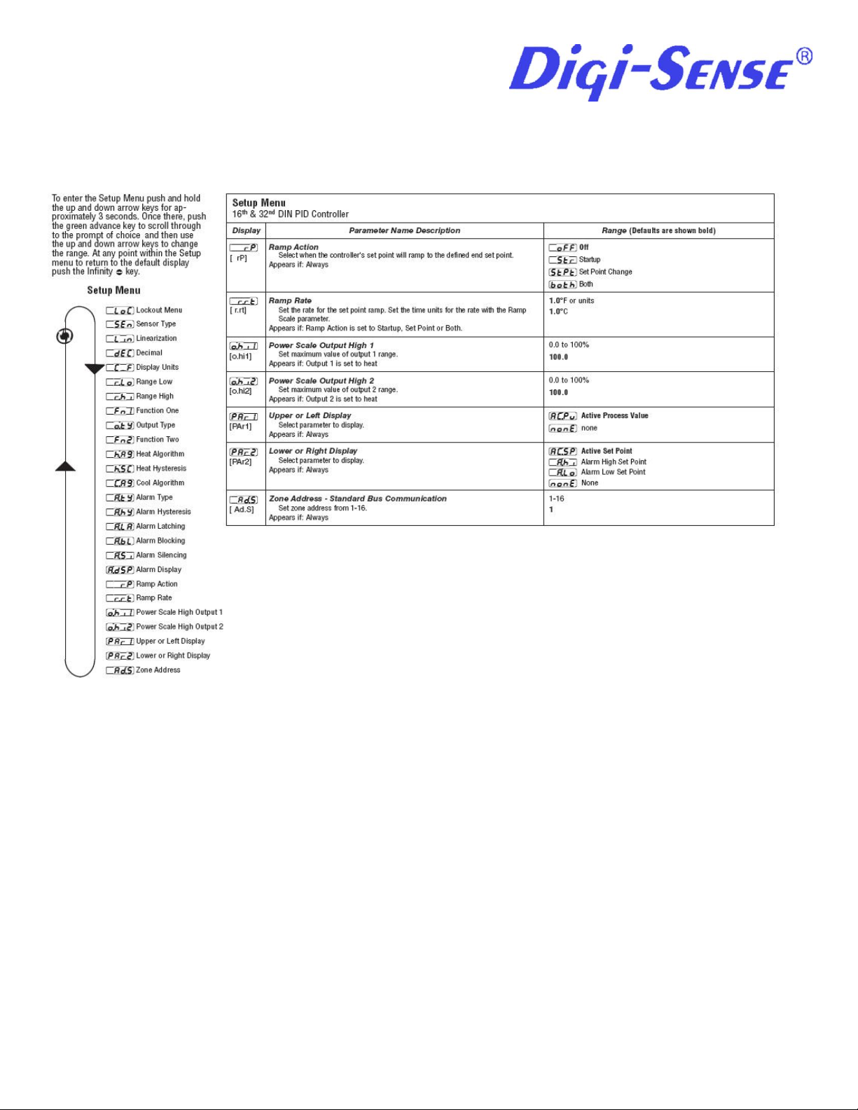
the UP/DOWN arrow keys simultaneously for three seconds to access the Setup Page. Press the Advance key until the
Celsius_Fahrenheit parameter [C-F] is shown in the lower display. Press the UP arrow key to change from C to F.
After changing the display, press the Infinity key to display the set point temperature and the process temperature
(temperature at the sensor).
To begin the heating application, use the Up/Down arrow keys to enter the desired set point temperature. This is shown
in the lower display. Press the Advance key to cycle through the Operations Page until the auto-tuning parameter [Aut] is
shown in the lower display. Auto-tuning is recommended in most applications. Auto-tuning allows the control to set the
parameters without those parameters being input by the user. It also minimizes the amount of temperature overshoot of
the set point and decreases the time required for the process to stabilize. To use the Ramp feature, refer to the
Ramp/Soak Operation section.
12/10 2 Rev.1
Page 3

Range Type J:
-200°C to 1200°C
Range Type K:
-200°C to 1370°C
Range Type T:
-200°C to 400°C
Range Type RTD:
-200°C to 800°C
After setting the auto-tuning parameter [Aut] to ON, press the Infinity key to display the set point and process
temperatures. While the control is in the auto-tuning mode, the lower display alternately flashes the set point and the "Aut"
prompt. When tuning is complete, the lower display indicates only the set point.
The auto-tuning function can be aborted by setting auto-tuning [Aut] to OFF or switching off power to the control.
It is recommended that auto-tuning be used each time a process is being run. If the process is being duplicated, the
parameters learned in the initial setup are stored in the memory of the control and no repeat of auto-tuning is required.
Auto-tuning feature allows quick and simple automatic control for the majority of heating applications. This control is
capable of performing other control functions and has a variety of features.
Control Sensor
Proper placement of the sensor can eliminate many problems in the total system. The probe should be placed so that it
can detect any temperature change with little thermal lag. In a process that requires fairly constant heat output, the probe
should be close to the heater. In processes where heat demand is variable, the probe should be close to the work area.
Some experimenting with probe location can be tried to provide optimum results.
Specifications
Control Mode
- Microprocessor-based, single input, single output.
- PID parameters
Proportional band: 1 to 999o F
Reset: 0.00 to 99.99 repeats per minute.
Integral: 0.00 to 99.99 minutes per repeat.
Rate or Derivative: 0.00 to 9.99 minutes.
Operator Interface
- Advance, Infinity, Up and Down keys and ON/OFF switch.
- Dual, four digit LED displays.
- Thermocouple receptacle or (RTD) and 3-wire load receptacle.
Input
- Type J, K , T thermocouple or (RTD): input grounded or ungrounded.
- Automatic cold junction compensation and break protection for sensor.
- Degrees F or degrees C display; user selectable (preset for degrees C)
Primary Output (Heating or Cooling)
- 15 Amp, 120 Volts.
Accuracy
- Calibration accuracy: 0.1% of span.
- Temperature stability: 0.2 oF / oF rise in ambient maximum.
- Voltage stability: 0.01% of span / % of rated line voltage.
Power
- 50/60 Hz 5%
- Data retention upon power failure via nonvolatile memory.
12/10 3 Rev.1
Page 4
Operating Environment
- 32 to 149 oF / 0 to 65 oC; 0 to 90% RH, non-condensing.
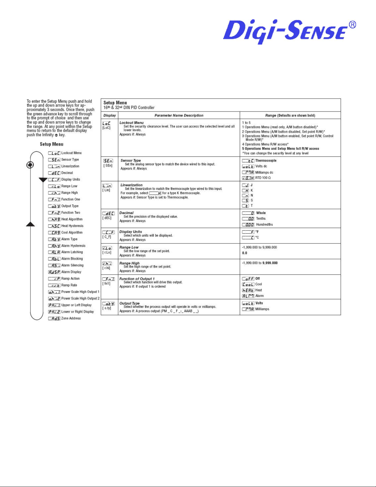
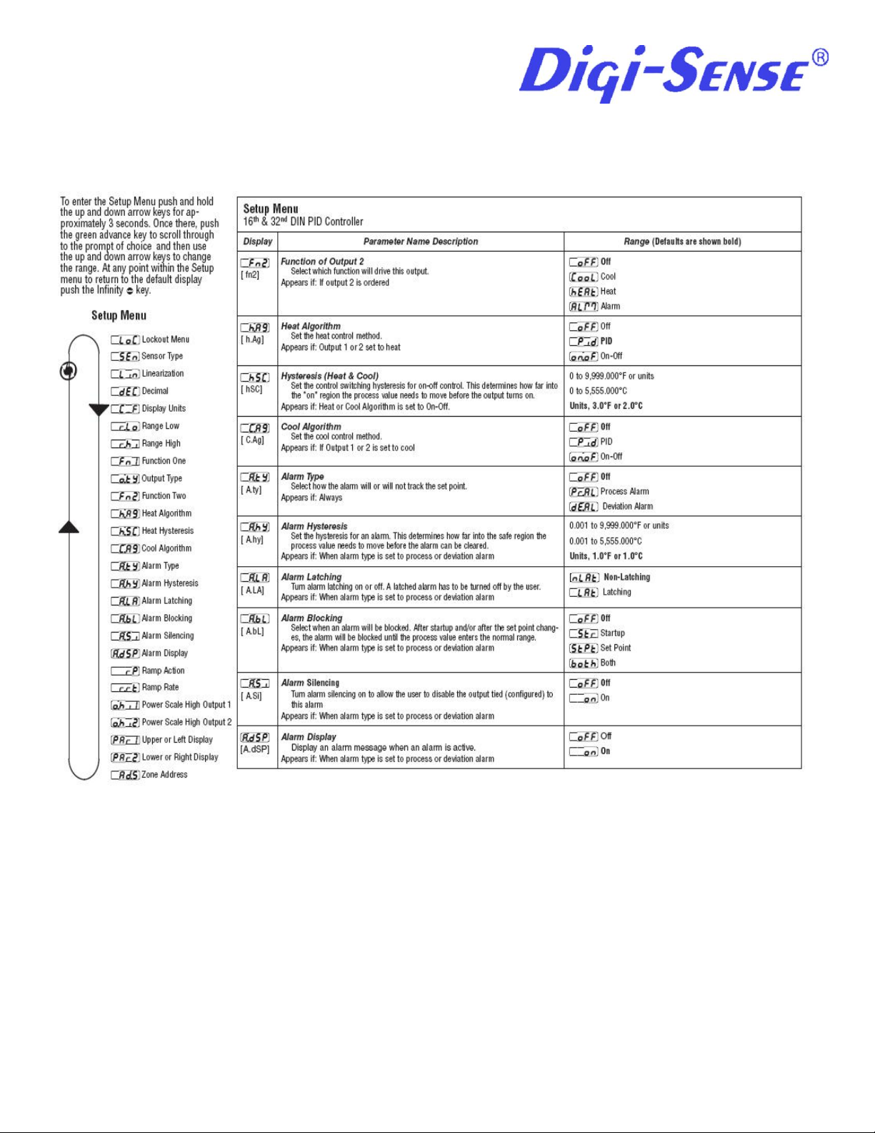
Setup Menu
12/10 4 Rev.1
Page 5
12/10 5 Rev.1
Page 6
12/10 6 Rev.1
Page 7
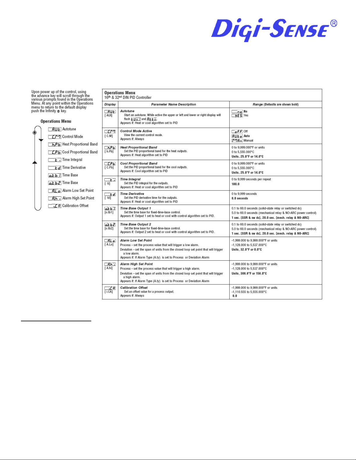
Operations Menu
How to Tune and Operate
Manual operation provides direct (time proportioned % time) control from -100% to 100%. A negative value is allowed
only when Ot 1=Cool. Automatic operation provides sensory feedback ON/OFF or PID control. When the operation
transfers from automatic to manual operation, the power level from automatic operation is retained and restored to the
previous set point.
The % LED indicates manual operation. The LED is on when in Manual operation and off when in AUTO operation.
When the LED is flashing, press the Infinity key again within 5 seconds to complete the change in operation. It the
sensor is open and LOC=0, 1 or 2, the control switches to Manual operation if the output was stable before the break
occurred.
12/10 7 Rev.1
Page 8

Tuning-Automatic
Auto-tuning: This control can automatically tune the PID parameters to fit the characteristics of your particular thermal
system.
Auto-tune can only be used when Output 1 is hEAt. Once the auto-tune sequence has begun, the lower display flashes
between AUt and the set point. The displayed set point remains unchanged.
Once the control finished "learning" the system, it returns to standard PID control with the values automatically set. Autotuning is complete within 80 minutes. Any change of the set point, while in auto-tune, re-initiates the auto-tune procedure.
In order for the control to successfully complete auto-tune, the process must cross set point four times within 80 minutes
after auto-tune has started. If this does not happen within the 80 minute time limit, Pb1 remains at 0 and the control
functions in an ON/OFF mode.
To start auto-tuning:
1. Press the Advance key until the Aut prompt appears in the lower display.
2. Change the parameter to On.
3. Press the Infinity key to display the set point and sensor temperatures. While the control is in the tuning mode,
the lower display alternately displays set point and the "Aut" prompt.
4. When tuning is complete, the lower display indicates setpoint only and Aut reverts to OFF. The control installs
appropriate PID tuning parameters and saves them in the non-volatile memory.
*To abort auto-tuning, the operator must reset Aut to OFF. Auto-tuning may also be aborted by cycling power off and on.
In all cases, aborting auto-tuning restores all original values.
Error Code Definitions and Actions:
Er.In - An open or reversed polarity sensor is the most likely cause. Check the sensor; if the connection is good and
functions properly, call the factory. Make sure the input parameter [SEn] is set to the correct type thermocouple.
Er.Ab – Ambient temperature may be too hot or too cold. Make sure that the temperature surrounding the control is –18 to
65C.
Er.CS – Checksum Error. Settings may have changed unexpectedly. Press the Infinity key to clear the error. Verify
settings. If error message persists, contact the factory.
To clear a corrected error, cycle power to the control.
12/10 8 Rev.1
Page 9

First Screen
Ramp/Soak Operation
The control is furnished with a CD for installation of a USB 2.0 to RS-485 driver. Before communicating with the control
through a pc this driver must be installed. Insert the CD into you pc and follow the instructions.
Once this is accomplished it is recommended to go to the Watlow web site, www.watlow.com and under the download
center tab, click on Software Download and install the EZ-Zone configuration software. This software will allow you to
easily set any parameter in the control and allow simple profile setup.
Once the software has been installed you can now attach the control to a pc and open the EZ-Zone configuration
software.
12/10 9 Rev.1
Page 10

Second Screen
Third Screen
12/10 10 Rev.1
Page 11

Forth Screen
12/10 11 Rev.1
Page 12

EZ-Zone Configurator software will now open and the following will appear on the screen:
12/10 12 Rev.1
Page 13

Continued:
12/10 13 Rev.1
Page 14

To activate the Ramp action, follow the below setup:
12/10 14 Rev.1
Page 15

Ramp Action Continued:
12/10 15 Rev.1
Page 16

12/10 16 Rev.1
Page 17

Select What Type this Step Will Be
Use Step Type to select what this step will do. The parameter list updates in a few seconds after the Step Type setting is changed.
• An Unused Step is, in effect, an empty step that can be used to erase a step in the profile.
• A Time step ramps to a Target Set Point over a specified time and maintains up to two Event states for the designated time.
• A Rate step ramps the process value to the Target Set Point without exceeding the Rate, while maintaining up to two Event outputs.
• A Soak step maintains the last Target Set Point and up to two Event states for the designated time.
• A Wait for Event step will wait for up to two Wait Events to be satisfied while maintaining up to two Event outputs.
• A Wait for Process step will wait for the process value to match the Wait for Process value, while maintaining up to two Event outputs.
• A Wait for Both step will wait for the process value to match the Wait for Process value and up to two Wait Events to be satisfied while
maintaining up to two Event outputs.
• A Jump Loop step will jump to the Jump Step the number of times designated in Jump Count, while maintaining up to two Event outputs.
• An End step will set up to two Event outputs and end the profile. If a profile doesn’t include an End step, control will move to the next step. If no
End step in encountered, after step 40 control will default to the set point in effect before the profile started.
12/10 17 Rev.1
Page 18

Profiling Page:
12/10 18 Rev.1
Page 19

Profiling Page Continued:
12/10 19 Rev.1
Page 20

Profiling Page Continued:
12/10 20 Rev.1
Page 21

GLOSSARY
Automatic prompts: Data entry points where a microprocessor-based control "prompts" or asks the operator for
information input.
Auto-tune: Automatically tunes the parameters to fit the characteristics of your particular thermal system.
Cold junction compensation: Electronic means to compensate for the effect temperature at the cold junction.
Cycle time: The time necessary to complete a full On-through-Off period in a time proportioning control system.
Derivative/Rate: Anticipatory action that senses the rate of change of the process, and compensates to minimize
overshoot and undershoot.
Default parameters: The parameters (programmed instructions) permanently stored in microprocessor software to
provide the data base.
Droop: Difference in temperature between set point and stabilized process temperature.
Hysteresis: In On/Off control, the temperature change necessary to change the output from On to full Off.
Input (sensor): Process variable information being supplied to the instrument.
Integral/Reset: Control action that automatically eliminates offset, or "droop", between set point and actual process
temperature.
Offset: Adjustment to actual input temperature and to the temperature valves the control uses for display and control.
ON/OFF control: Control of temperature about a set point by turning the output full On below set point and full Off above
set point.
Output: Action in response to difference between set point and process variable.
Overshoot: Condition where temperature exceeds steeping due to initial power up or process changes.
Parameter: a physical property whose value determines the response of a electronic control to given inputs.
PID: Proportioning control with auto-reset and rate.
Process variable: Thermal system element to be regulated, such as time, temperature, relative humidity, etc.
Proportional band: Span of temperature about the set point where time proportional control action takes place.
Set point: Intended value of the process variable.
Thermal system: A regulated environment consisting of a heat source, heat transfer medium, sensing device and a
process variable control.
Thermocouple: Temperature sensing device that is constructed of two dissimilar metals wherein a measurable,
predicative voltage is generated corresponding to temperature.
12/10 21 Rev.1
Page 22

Digi-Sense
625 East Bunker Court, MS 18
Vernon Hills, Illinois 60061-1844, U.S.A
Phone: 847-549-7600 Fax: 847-549-7676
( 800) 323-4340
Thermocouple break protection: Fail-safe operation that assures output shutdown upon an open thermocouple condition.
Time Proportioning Control: Action which varies the amount of ON and OFF time when "close" to the set point (within the
proportional band). This variance is proportional to the difference between the set point and the actual process
temperature.
Maintenance
Simple preventative maintenance steps include keeping the controller clean. Protect it from overload, excessive dirt, oil
and corrosion.
Warranty
Digi-Sense, for itself does hereby offer a warranty for products from the date of receipt by the user, under normal and
proper usage, against defects in workmanship and materials for 12 months, and will repair or replace any defective
part(s) without charge when same is shipped Prepaid to Digi-Sense from which the product was originally purchased.
Should the nature of any defect require that the product, or any constituent portion thereof, be returned to Digi-Sense,
Vernon Hill, Illinois, prepaid for service, a condition precedent to any return shall be the procurement of authorization from
Digi-Sense assigning a Return Goods Number to the product or part requiring service.
Parts and accessories manufactured by others are warranted only to the extent of the regular warranty of the
manufacturer or supplier of such materials and only insofar as Digi-Sense is able to transfer the benefits of warranty
coverage, if any, to the user. Any adequately warranted defective part or accessory manufactured or supplied by others
may be exchanged through Digi-Sense for a replacement part is shipped prepaid and received at Digi-Sense within 30
days from the date any replacement part is obtained by the user.
This warranty supersedes and is given in lieu of all implied warranties, and is void if the user causes damages from
improper usage of product under normal operating conditions.
12 MONTHS LIMITED WARRANTY ON ALL PARTS AND LABOR IS GIVEN BY DIGI-SENSE.
CATALOG NUMBER 3622566, 3622567, 3622568, 3622569
SERIAL NUMBER _________
DATE OF PURCHASE _______________
12/10 22 Rev.1
 Loading...