

Page 1
User Manual
THE STANDARD IN PRECISION MEASUREMENT
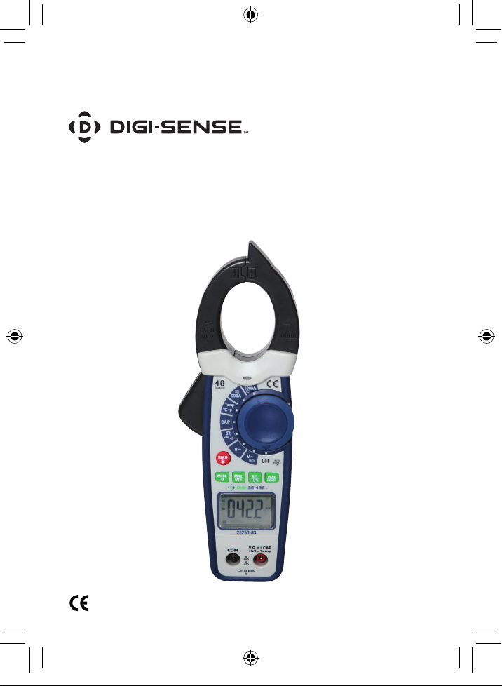
AC/DC True RMS Clamp Meter
with Bluetooth
NIST-Traceable Calibration
®
Mobile App and
Model 20250-63
1065DGMAN_20250-63_Rev1.indd 1 07/02/2019 10:31:06 AM
Page 2

Introduction
The Digi-Sense AC/DC True RMS Clamp Meter with
Bluetooth
to transmit data directly to your Android
®
Connectivity (model 20250-63) allows you
™
or iOS®
device using our free D/S Meter mobile app. Now
you can view data at a safe distance from potentially
hazardous parameters or even use your smart device
as a real-time secondary display for checking measurements, eliminating the need to write down readings
on paper. The results are automatically stored in the
app with a date-and-time stamp and can be saved as
a CSV file and emailed for future reference, manipulation, or analysis to help determine trends and conditions over a long period of time. You can also use the
app to attach photos and notes to the records creating
a clear reference point for your work.
Setup is simple. Download the free D/S Meter app to
your Android or iOS device. Place the clamp meter in
Bluetooth mode and open the app on your smart
device. The clamp meter will be sensed by your device
and be listed as an available source that you can select.
Once selected, the measured data is displayed on your
device and some of the instrument functions can also be
accessed. A full description of its operation is available
for download in the app.
The AC/DC TRMS Clamp Meter measures AC current
to 1000 A AC, voltage (AC and DC), resistance, capacitance, frequency, temperature, duty cycle, and continuity. Special functions include auto ranging, diode test,
and audible continuity check. This instrument is fully
tested and calibrated to NIST-traceable standards for
reliable measurements right out of the box, saving
you time and money.
2
1065DGMAN_20250-63_Rev1.indd 2 07/02/2019 10:31:06 AM
Page 3
Safety
International Safety Symbols
This symbol, adjacent to another symbol or
terminal, indicates the user must refer to the
manual for further information.
This symbol, adjacent to a terminal, indicates
that, under normal use, hazardous voltages may
be present
Double insulation
SAFETY NOTES
• Do not exceed the maximum allowable input range
of any function:
Function Maximum Input
A AC, A DC 1000 A DC/AC
V DC, V AC 750 V DC/AC
Resistance, Capacitance, Frequency,
Diode Test
Temperature 300 V DC/ AC
• Do not apply voltage to meter when resistance
function is selected.
• Set the rotary function switch OFF when the meter
is not in use.
• Remove the battery if meter is to be stored for longer
than 60 days.
300 V DC/AC
1065DGMAN_20250-63_Rev1.indd 3 07/02/2019 10:31:07 AM
3
Page 4

WARNINGS
• Set rotary function switch to the appropriate position
before measuring.
• When measuring volts do not switch to current/
resistance modes.
• Do not measure current on a circuit whose voltage
exceeds 600 V.
• When changing ranges always disconnect the test
leads from the circuit under test.
• Changes or modifications to this unit not expressly
approved by the party responsible for compliance could
void the user's authority to operate the equipment.
Note: This equipment has been tested and found to
comply with the limits for a Class B digital device,
pursuant to Part 15 of the FCC Rules. These limits are
designed to provide reasonable protection against
harmful interference in a residential installation. This
equipment generates, uses and can radiate radio frequency energy and, if not installed and used in accordance with the instructions, may cause harmful
interference to radio communications. However, there
is no guarantee that interference will not occur in a
particular installation. If this equipment does cause
harmful interference to radio or television reception,
which can be determined by turning the equipment off
and on, the user is encouraged to try to correct the
interference by one or more of the following measures:
• Reorient or relocate the receiving antenna.
• Increase the separation between the equipment and
receiver.
4
1065DGMAN_20250-63_Rev1.indd 4 07/02/2019 10:31:07 AM
Page 5

• Connect the equipment into an outlet on a circuit dif-
ferent from that to which the receiver is connected.
• Consult the dealer or an experienced radio/TV
technician for help.
CAUTIONS
• Improper use of this meter can cause damage,
shock, injury or death. Read and understand this
user manual before operating the meter.
• Always remove the test leads before replacing the
battery.
• If the test leads need to be replaced, you must use a
new one which should meet EN 61010-031 standard.
• Inspect the condition of the test leads and the meter
itself for any damage before operating the meter.
Repair or replace any damage before use.
• Use great care when making measurements if the
voltages are greater than 25 VAC rms or 35 VDC.
These voltages are considered a shock hazard.
• Always discharge capacitors and remove power
from the device under test before performing Diode,
Resistance or Continuity tests.
• Voltage checks on electrical outlets can be difficult and
misleading because of the uncertainty of connection to
the recessed electrical contacts. Other means should be
used to ensure that the terminals are not "live".
• If the equipment is used in a manner not specified by
the manufacturer, the protection provided by the
equipment may be impaired.
1065DGMAN_20250-63_Rev1.indd 5 07/02/2019 10:31:07 AM
5
Page 6

Unpacking
Check individual parts against the list of items
below. If anything is missing or damaged, please
contact your instrument supplier immediately.
1. Meter
2. Test leads
3. One type K temperature probe
4. One 9 V battery
5. Carrying case
6. User manual
7. NIST-traceable calibration report with data
Key Features
• Bluetooth interface
• User-friendly mobile app
• Noncontact AC voltage indicator light
• Temperature measurement via type K thermocouple
• 1.2" (30 mm) clamp jaw opening
• Electronic overload protection
• Auto-ranging with auto power-off
• Data Hold function; Max/Min readings
6
1065DGMAN_20250-63_Rev1.indd 6 07/02/2019 10:31:07 AM
Page 7

Meter Description
1. NCV test
2. Current clamp
3. Noncontact AC
voltage indicator
light
4. Clamp trigger
5. Rotary function
switch
6. Data HOLD and
Backlight button
7. PEAK and INRUSH
button
8. REL and Hz%
button
9. MODE select
and Bluetooth
button
10. Max/Min button
11. LCD
12. V Ω
13. COM input jack
14. Battery compartment
(on rear)
•))) CAP Hz% Temp
1065DGMAN_20250-63_Rev1.indd 7 07/02/2019 10:31:07 AM
7
Page 8

Display Layout
HOLD Data Hold
Minus sign Negative reading display
0 to 5999 Measurement display digits
REL REL/ DCA Zero
MAX/MIN Maximum/Minimum
AUTO Autorange mode
DC/AC Direct Current / Alternating Current
mV or V Milli-volts or Volts (Voltage)
Ohms
A Amperes (Current)
F Farad (Capacitance)
Hz/% Hertz (Frequency)/Percent(duty ratio)
°F and °C Fahrenheit and Celsius units (Temperature)
n, m, μ, M, k
•))) Continuity test
8
Auto Power-off
Low battery
Mk
Ω (Resistance)
Unit of measure prefixes: nano, milli,
micro, mega, and kilo
Diode test
Bluetooth 4.0
1065DGMAN_20250-63_Rev1.indd 8 07/02/2019 10:31:07 AM
Page 9

Setup and Operation
NOTE: Read and understand all Warning and Caution statements
in this user manual prior to using this meter. Set the rotary function
switch to the OFF position when the meter is not in use.
AC/DC Current Measurements
WARNING: Ensure that the test leads are disconnected from the meter
before making current clamp measurements.
1. Set the rotary function switch to the 1000 A or 600 A range. If the
approximate range of the measurement is not known, select the
highest range then move to the lower range if necessary.
2. Press the REL button to zero the meter display.
3. Use the MODE button to select AC or DC Current.
4. Press the trigger to open jaw. Fully enclose only one conductor.
For optimum results, center the conductor in the jaw.
5. The clamp meter LCD will display the reading.
AC Voltage Measurement
1. Insert the black test lead into the negative COM terminal and the red
test lead into the positive V Ω
2. Set the rotary function switch to the V~ position.
3. Connect the test leads in parallel to the circuit under test.
4. Read the voltage measurement in the display.
))
•
) CAP Hz% Temp terminal.
1065DGMAN_20250-63_Rev1.indd 9 07/02/2019 10:31:07 AM
9
Page 10

DC Voltage Measurement
1. Insert the black test lead into the negative COM terminal and the red
test lead into the positive V Ω
2. Set the rotary function switch to the V– position.
3. Connect the test leads in parallel to the circuit under test.
4. Read the voltage measurement in the display.
))
•
) CAP Hz% Temp terminal.
Resistance Measurements
1. Insert the black test lead into the negative COM terminal and the red
test lead into the V Ω
2. Set the rotary function switch to the
3. Touch the test probe tips across the circuit or component under test.
4. Read the resistance measurement in the display.
))
•
) CAP Hz% Temp positive terminal.
))
Ω
•
) position.
Capacitance Measurements
WARNING: To avoid electric shock, discharge the capacitor
under test before measuring.
1. Set the rotary function switch to the CAP position.
2. Insert the black test lead banana plug into the negative COM jack
and the red test lead banana plug into the V Ω
Temp positive jack.
3. Touch the test probe tips across the part under test. If “OL” appears
in the display, remove and discharge the component.
4. Read the capacitance value in the display.
5. The display will indicate the proper decimal point and value.
Note: For very large values of capacitance measurement, it can take
several minutes before the final reading stabilizes.
))
•
) CAP Hz%
10
1065DGMAN_20250-63_Rev1.indd 10 07/02/2019 10:31:08 AM
Page 11

Frequency Measurements
1. Insert the black test lead banana plug into the negative COM jack
and the red test lead banana plug into the V Ω
Temp positive jack.
2. Set the rotary function switch to the V~ position.
3. Press Hz% button to select the Frequency (Hz) or Duty cycle (%).
4. Touch the test probe tips across the part under test.
5. Read the value on the display.
6. The display will indicate the proper decimal point and value.
7. In Voltage and Current mode, press Hz% button to select Frequency
(Hz) or Duty cycle (%).
))
•
) CAP Hz%
Temperature Measurements
WARNING: To avoid electric shock, be sure the thermocouple probe
has been removed before changing to another measurement function.
1. Set the rotary function switch to the TEMP position.
2. Insert the Temperature Probe into the negative COM and the
V Ω
3. Touch the temperature probe head to the device under test.
Continue to touch the part under test with the probe until the
reading stabilizes.
4. Read the temperature on the display. The digital reading will
indicate the proper decimal point and value.
5. Use the MODE button to select °F or °C.
))
•
) CAP Hz% Temp positive jacks, observing polarity.
1065DGMAN_20250-63_Rev1.indd 11 07/02/2019 10:31:08 AM
11
Page 12

Continuity Measurements
1. Insert the black test lead into the negative COM terminal and the
red test lead into the V Ω
terminal.
))
•
) CAP Hz% Temp positive
2. Set the rotary function switch the Ω
3. Use the MODE button to select continuity “•
•))) position.
))
)”. The display icons
will change when the MODE button is pressed.
4. Touch the test probe tips across the circuit or component under test.
5. If the resistance is <50 Ω, a tone will sound.
Diode Test
1. Insert the black test lead banana plug into the negative COM jack
and the red test lead banana plug into the V Ω
Hz% Temp positive jack
Ω
2. Turn the rotary function switch to the
•
MODE button to select the diode function if necessary (diode symbol
will appear on the LCD when in Diode test mode).
3. Touch the test probe tips to the diode or semiconductor junction
under test. Note the meter reading.
4. Reverse the test lead polarity by reversing the red and black leads.
Note this reading.
5. The diode or junction can be evaluated as follows:
- If one reading displays a value (typically 0.400 V to 0.900 V) and
the other reading displays OL, the diode is good.
- If both readings display OL, the device is open.
- If both readings are very small or ‘0’, the device is shorted.
))
•
) CAP
))
) position. Use the
12
1065DGMAN_20250-63_Rev1.indd 12 07/02/2019 10:31:08 AM
Page 13

Noncontact AC Voltage Measurements
WARNING: Risk of Electrocution. Before use, always test the
Voltage Detector on a known live circuit to verify proper operation.
1. Touch the probe tip to the hot conductor or insert into the hot side of
the electrical outlet.
2. If AC voltage is present, the detector light will illuminate.
Note: The conductors in electrical cord sets are often twisted. For best
results, rub the probe tip along a length of the cord to assure placing
the tip in close proximity to the live conductor.
Note: The detector is designed with high sensitivity. Static electricity
or other sources of energy may randomly trip the sensor. This is
normal operation.
MODE/Bluetooth Button
Press the MODE/Bluetooth button to select between functions
when a multifunction position is selected. For example, you can
select between measuring voltage, diode, or continuity “V
by turning to that switch position and then toggling between the
functions by pressing the Mode/Bluetooth button. Also functions in
“˚F or ˚C” and “AC or DC” current switch settings.
Press and hold the MODE/Bluetooth button to turn the system on;
the auto power-off function will be cancelled.
Press the MODE/Bluetooth button until the Bluetooth turns on or
off, indicated by the Bluetooth icon on the display.
))
•
)“
1065DGMAN_20250-63_Rev1.indd 13 07/02/2019 10:31:08 AM
13
Page 14

PEAK/INRUSH Button
Note: Only ACV functions can do the PEAK value measurement.
1. PEAK Key is the peak value measurement key that acts with trigger.
2. In ACV functions, press PEAK/INRUSH button to activate the detection
of Maximum and Minimum peak AC Voltage values with a response
time of 1 ms. Both values are constantly updated and are displayed
cyclically every time the same button is pressed again.
3. The display shows the symbol associated with the selected function:
“PMAX” for maximum peak value, “PMIN” for minimum peak value.
Note: For ACA functions, only the INRUSH value measurement is possible.
1. Turn off the meter and then insert conductor into jaw.
2. Press the PEAK/INRUSH button , “----”will appear in the display.
3. Turn on the meter and then read the value on the display.
Data HOLD/Backlight Button
To freeze the LCD reading, press the HOLD button. While data hold is
active, the HOLD icon appears on the LCD. Press the HOLD button again
to return to normal operation. The LCD is equipped with backlighting for
easier viewing, especially in dimly lit areas. Press the backlight button to
turn the backlight on. Press again to turn the backlight off.
Relative Button
1. Press the REL button to zero the display; “REL” will appear in the
display. The displayed reading is now the actual value less the stored
“zero” value.
2. Press the REL button to view the stored value; “REL” will flash in the
display.
3. To exit this mode, press and hold the REL button until “REL” is
no longer visible in the display.
14
1065DGMAN_20250-63_Rev1.indd 14 07/02/2019 10:31:08 AM
Page 15

MAX/MIN Button
1. Press MAX/MIN key to measure the maximum and minimum values.
This mode is activated on each measurement except for continuity
test, diode test capacitance test, frequency test, and duty cycle test.
2. The MAX/MIN mode is disabled by holding the MAX/MIN button
down for several seconds or by moving the rotary function switch.
HZ%
When the rotary function switch is on the Hz%, Voltage, or Current
position, the Hz% button allows you to select the frequency test (Hz)
or the duty cycle test (%).
LCD Backlight Button
The LCD is equipped with backlighting for easier viewing, especially in
dimly lit areas. Press the HOLD/backlight button to turn the backlight
on. Press again to turn the backlight off.
Automatic Power-Off
In order to conserve battery life, the meter will automatically turn off
after approximately 15 minutes of nonuse. To turn the meter on again,
turn the rotary function switch to the OFF position and then to the
desired function position.
1065DGMAN_20250-63_Rev1.indd 15 07/02/2019 10:31:08 AM
15
Page 16

Specifications
Function Range Resolution
AC True RMS
Current
(Auto-ranging)
Over-range protection: maximum input 1000 A
Accuracy specified from 5% to 100% of the measuring range
Frequency response: 50 Hz to 60 Hz True RMS
60.00 A 10 mA +2.5% of rdg + 8 digits
600.0 A 100 mA +2.5% of rdg + 8 digits
1000 A 1 A +2.8% of rdg + 8 digits
Function Range Resolution
DC Current
(Auto-ranging)
Over-range protection: maximum input 1000 A
60.00 A 10 mA +2.5% of rdg + 8 digits
600.0 A 100 mA +2.5% of rdg + 8 digits
1000 A 1 A +2.8% of rdg + 8 digits
Function Range Resolution
(% of reading + digits)
(% of reading + digits)
(% of reading + digits)
600.0 mV 0.1 mV +0.9% of rdg + 5 digits
DC Voltage
(Auto-ranging)
6.000 V 1 mV +1.0% of rdg + 3 digits
60.00 V 10 mV +1.0% of rdg + 3 digits
600.0 V 100 mV +1.0% of rdg + 3 digits
Maximum input: 750 V dc
Function Range Resolution
AC True RMS
Voltage
(Auto-ranging)
AC response: 50 Hz to 1 kHz
Accuracy specified from 5% to 100% of the measuring range
Accuracy PEAK function: ±10% rdg
Maximum input: 750 V ac rms
6.000 V 1 mV +1.2% of rdg + 5 digits
60.00 V 10 mV +1.2% of rdg + 5 digits
600.0 V 100 mV +1.5% of rdg + 5 digits
(% of reading + digits)
Accuracy
Accuracy
Accuracy
Accuracy
16
1065DGMAN_20250-63_Rev1.indd 16 07/02/2019 10:31:08 AM
Page 17

Function Range Resolution
600.0 Ω 0.1 Ω +1% of rdg + 4 digits
6.000 kΩ 1 Ω +1.5% of rdg + 2 digits
Resistance
(Auto-ranging)
60.00 kΩ 10 Ω +1.5% of rdg + 2 digits
600.0 kΩ 100 Ω +1.5% of rdg + 2 digits
6.000 MΩ 1 kΩ +2.0% of rdg + 5 digits
60.00 MΩ 10 kΩ +3% of rdg + 8 digits
Input protection: 300 V dc or 300 V ac rms
Accuracy
(% of reading + digits)
Function Range Resolution
Accuracy
(% of reading + digits)
60.00 nF 10 pF +5% of rdg + 30 digits
600.0 nF 0.1 nF +3% of rdg + 5 digits
Capacitance
(Auto-ranging)
6.000 μF 1 nF +3% of rdg + 5 digits
60.00 μF 10 nF +3% of rdg + 5 digits
600.0 μF 0.1 μF +4% of rdg + 10 digits
6000 μF 10 μF +4.5% of rdg + 10 digits
Input protection: 300 V dc or 300 V ac rms
Accuracy is not stated below 6 nF
Frequency with Test Leads (AC Voltage)
Function Range
Frequency
(Auto-ranging)
Input protection: 750 V AC rms
Sensitivity: >15 V AC rms
10 Hz to 20 kHz ±(1.0% + 5 digits)
Function Range
Frequency 40 Hz to 1 kHz ±(1.0% + 5 digits)
Maximum input: 1000 A AC
Sensitivity: >50 A (600 A range); >500 A (1000 A range)
Accuracy
(% of reading + digits)
Accuracy
(% of reading + digits)
17
1065DGMAN_20250-63_Rev1.indd 17 07/02/2019 10:31:08 AM
Page 18

Function Range Resolution
Accuracy
(% of reading + digits)
Duty Cycle 20.0% to 80.0% 0.1 +1.2% of rdg + 10 digits
Function Range Resolution
Temperature
Sensor: Type K thermocouple
Input protection: 300 V dc or 300 V ac rms
–20 to 760°C 0.1/1°C +3% of rdg + 5°C
–4 to 1400°F 0.1/1°F +3% of rdg + 9°F
Accuracy
(% of reading + digits)
Function Testing condition Reading
Diode
is approx.1 mA, open circuit
Voltage MAX . 3 V
Forward DCA
Continuity
Input protection: 300 V dc or 300 V ac rms
Test current
MAX. 1.5 mA
Forward voltage
drop of Diode
Buzzer makes a
long sound when
resistance is <50 Ω
General Specifications
Clamp jaw opening 1.2" (30 mm) approx.
Bluetooth version 4.0
Display 6000 counts LCD, backlighting
Continuity check Threshold 50 Ω; Test current <0.5 mA
Diode test Test current of 0.3 mA typical;
Low battery indication is displayed
Over-range indication ‘OL’ display
Measurement rate 3 readings per second, nominal
PEAK Captures peaks >1ms
INRUSH 100 MS
Temperature sensor Type K thermocouple
Open circuit voltage <3 VDC typical
18
1065DGMAN_20250-63_Rev1.indd 18 07/02/2019 10:31:08 AM
Page 19

Input Impedance 10 MΩ (VDC and VAC)
AC response True RMS (AAC and VAC)
Operating temperature 41 to 104°F (5 to 40°C)
Storage temperature –4 to 140°F (–20 to 60°C)
Operating humidity Max 80% up to 87°F (31°C) decreasing
linearly to 50% at 104°F (40°C)
Storage humidity <80%
Operating altitude 7000 ft (2000 m) maximum
Battery One (1) 9 V battery
Auto power-off Approximately 15 minutes
Dimensions 913⁄32" x 35⁄32" x 115⁄16" (23.9 x 8 x 4.9 cm)
Weight 10.8 oz (305 g)
Safety Conforms to UL STD. 61010-1, 61010-2-030,
61010-2-033 and 61010-031;
Certified to CSA STD. C22.2, NO. 61010-1,
61010-2-30, 61010-2-033 and 61010-031.
Maintenance, Recalibration, and Repair
WARNING: To avoid electrical shock, disconnect the meter from any
circuit, remove the test leads from the input terminals, and turn OFF
the meter before opening the case. Do not operate the meter with an
open case.
Cleaning and Storage
Periodically wipe the case with a damp cloth and mild detergent;
do not use abrasives or solvents. If the meter is not to be used for
60 days or more, remove the battery and store it separately.
Battery Replacement
1. Remove the Phillips head screw that secures the rear battery door.
2. Open the battery compartment.
3. Replace the 9 V battery.
4. Secure the battery compartment.
1065DGMAN_20250-63_Rev1.indd 19 07/02/2019 10:31:08 AM
19
Page 20

It is recommended that Digi-Sense products are calibrated
annually to ensure proper function and accurate measure-
ments; however, your quality system or regulatory body
may require more frequent calibrations. To schedule your
recalibration, please contact InnoCal, an ISO 17025
calibration laboratory accredited by A2LA.
Phone: 1-866-INNOCAL (1-866-466-6225)
Fax: 1-847-327-2993
E-mail: sales@innocalsolutions.com
Web: InnoCalSolutions.com
For Product and Ordering Information, Contact:
Toll-Free: 1-800-323-4340
Phone: 1-847-549-7600
Fax: 1-847-247-2929
ColeParmer.com/Digi-Sense
1065DGMAN_20250-63_Rev1
1065DGMAN_20250-63_Rev1.indd 20 07/02/2019 10:31:08 AM
Manual Part No. 00101-99
 Loading...