

Page 1
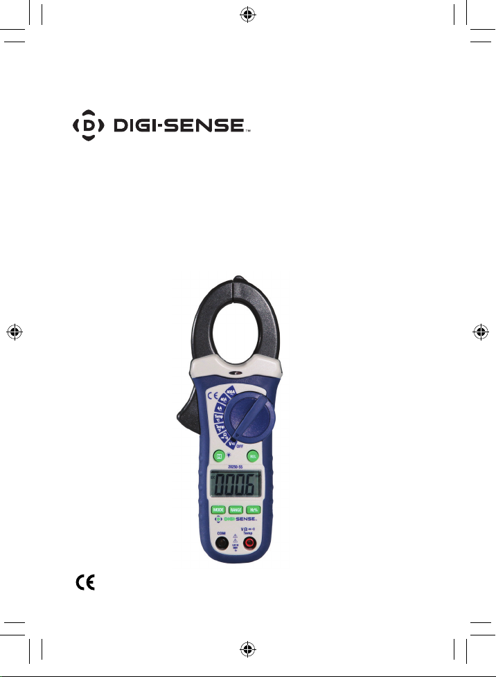
THE STANDARD IN PRECISION MEASUREMENT
User Manual
Compact Autoranging Clamp Meters
with NIST-Traceable Calibration
Models 20250-55 (400 A AC),
20250-56 (400 A AC/DC)
1065DGMAN_20250-55,-56 DS Clamp Meter Man.indd 1 8/7/2017 2:22:29 PM
Page 2
Introduction
The Digi-Sense Compact Autoranging Clamp Meters (400 A
AC Model 20250-55; 400 A AC/DC Model 20250-56) offer all
the basic features needed for measurement. The doublemolded plastic housing and jaw are designed for use in
tight places. A large backlit display provides easy-to-read
measurements. The instruments are fully tested and calibrated to NIST-traceable standards. Careful use of the
meter will provide years of reliable service.
Safety
International Safety Symbols
This symbol, adjacent to another symbol or terminal,
indicates the user must refer to the manual for
further information.
This symbol, adjacent to a terminal, indicates that,
under normal use, hazardous voltages may be
present
Double insulation
1065DGMAN_20250-55,-56 DS Clamp Meter Man.indd 2 8/7/2017 2:22:29 PM
2
Page 3
SAFETY NOTES
• Do not exceed the maximum allowable input range of any
function.
• Do not apply voltage to meter when resistance function is
selected.
• Set the function switch OFF when the meter is not in use.
WARNINGS
• Set rotary function switch to the appropriate position
before measuring.
• When measuring volts, do not switch to current/resistance
modes.
• When changing ranges using the rotary function switch,
always disconnect the test leads from the circuit under
test.
• Do not exceed the maximum rated input limits:
Input Limits
Function
Maximum Input,
Model 20250-55
Maximum Input,
Model 20250-56
A 400 A AC 400 A AC/DC
V 600 V AC/DC 600 V AC/DC
Frequency, Duty
cycle, Resistance,
Diode, Continuity,
250 V AC/DC 250 V AC/DC
Capacitance Test
1065DGMAN_20250-55,-56 DS Clamp Meter Man.indd 3 8/7/2017 2:22:29 PM
Temperature (°C/°F) 250 V AC/DC 250 V AC/DC
3
Page 4

CAUTIONS
• Improper use of this meter can cause damage, shock,
injury or death. Read and understand this user manual
before operating the meter.
• Always remove the test leads before replacing the
battery.
• Inspect the condition of the test leads and the meter
itself for any damage before operating the meter. Repair
or replace any damage before use.
• Use great care when making measurements if the
voltages are greater than 25 VAC rms or 35 VDC. These
voltages are considered a shock hazard.
• Remove the battery if the meter is to be stored for long
periods.
• Always discharge capacitors and remove power from
the device under test before performing Diode,
Resistance, or Continuity tests.
• Voltage checks on electrical outlets can be difcult and
misleading because of the uncertainty of connection to
the recessed electrical contacts. Other means should be
used to ensure that the terminals are not "live".
• If the equipment is used in a manner not specied by the
manufacturer, the protection provided by the equipment
may be impaired.
1065DGMAN_20250-55,-56 DS Clamp Meter Man.indd 4 8/7/2017 2:22:29 PM
4
Page 5

Unpacking
Check individual parts against the list of items below. If
anything is missing or damaged, please contact your
instrument supplier immediately.
1. Meter
2. Test leads
3. Temperature probe
4. Carrying case
5. 9 V battery
6. User manual
7. NIST-traceable calibration report with data
Key Features
• Built-in noncontact AC voltage detector
• Durable double-molded housing
3
• 1
⁄16" (30 mm) jaw opening
• CAT III 1000 V safety rating
• Electronic overload protection
• Autoranging with auto power-off
• Peak Hold function that captures the peak AC current or
voltage reading (model 20250-56 only)
1065DGMAN_20250-55,-56 DS Clamp Meter Man.indd 5 8/7/2017 2:22:29 PM
5
Page 6
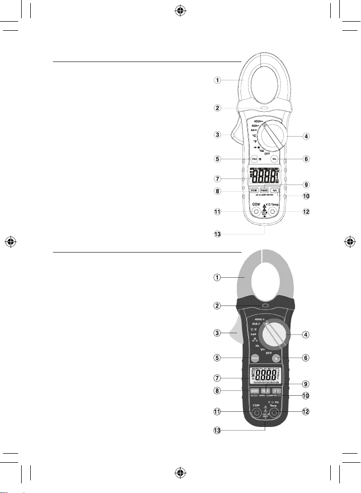
Meter Description (Model 20250-55)
1. Current clamp
2. Noncontact AC voltage
indicator light
3. Clamp trigger
4. Rotary function switch
5. Data HOLD / Backlight button
6. Relative button
7. 4000-count LCD
8. MODE select button
9. Range button
10. Hz% button
11. COM input jack
12. V Ω CAP TEMP Hz jack
13. Battery cover
Meter Description (Model 20250-56)
1. Current clamp
2. Noncontact AC voltage
indicator light
3. Clamp trigger
4. Rotary function switch
5. Data HOLD button
6. Backlight button
7. 4000-count LCD
8. MODE select button
9. PEAK button
10. Relative button
11. COM input jack
12. V Ω CAP TEMP Hz jack
13. Battery cover
6
Ω
1065DGMAN_20250-55,-56 DS Clamp Meter Man.indd 6 8/7/2017 2:22:31 PM
Page 7
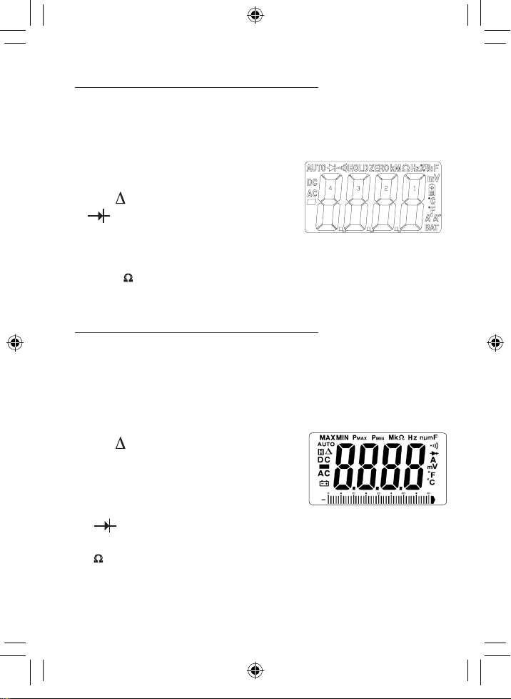
Display Layout (Model 20250-55)
1. AC DC AC (alternating current) and
DC (direct current)
2.
Minus sign
–
3. 8.8.8.8 4000 count (0 to 3999)
measurement reading
4. AUTO Autorange mode
5. REL (
6.
7. •))) Audible continuity
8. HOLD Data HOLD mode
9. °C,°F,µm,V,
A,K,M,
10. Hz % Frequency/duty cycle test mode
) Relative mode
Diode test mode
Ω Units of measure list
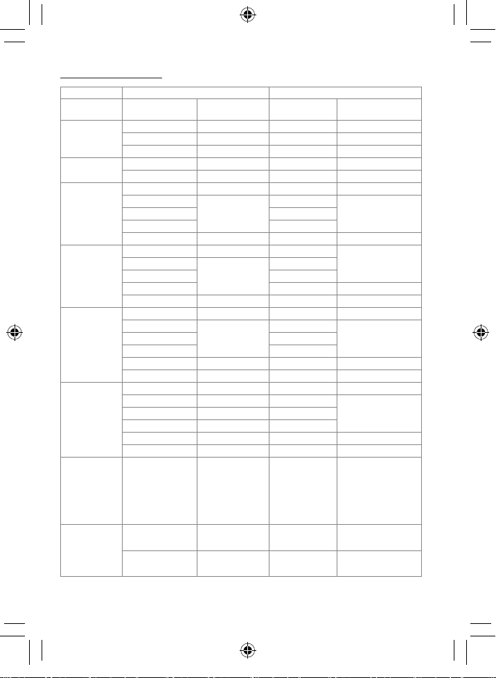
Display Layout (Model 20250-56)
1. AC DC AC (alternating current) and DC
(direct current)
2.
Minus sign
–
3. 8.8.8.8 4000 count (0 to 3999) measurement
reading with analog bar graph
4. HOLD Data HOLD mode
5. REL (
6. AUTO Autorange mode
7. MAX MIN Max/Min Hold mode
8. Pmax Pmin Pmax Pmin Hold mode
9. •))) Audible continuity
10.
11. Hz % Frequency/duty cycle test mode
12.
°C,°F Units of measure list
) Relative mode
Diode test mode
Ω,F,A,V,
1065DGMAN_20250-55,-56 DS Clamp Meter Man.indd 7 8/7/2017 2:22:31 PM
7
Page 8

Setup and Operation
Note: Read and understand all warning and precaution
statements listed in the safety section of this operation
manual prior to using this meter. Set the rotary function
switch to the OFF position when the meter is not in use.
AC and AC/DC Current Measurements
WARNING: Ensure that the test leads are disconnected
from the meter before making current clamp measurements.
1. Set the rotary function switch to the
400A or 40A or 4A range.
2. For model 20250-56
only, select AC or
DC by pressing the
MODE button.
3. If the measuring
range is unknown,
select the higher
Ω
range rst then
move to the lower
range as necessary.
4. Press the trigger to
open jaw. Fully
enclose one conductor to be measured (see diagram).
The LCD will display the reading.
5. In DCA mode, to ensure the reading is correct, press
the REL button to clear the reading on the LCD before
measurement. The LCD will display the reading (model
20250-56 only).
Ω
1065DGMAN_20250-55,-56 DS Clamp Meter Man.indd 8 8/7/2017 2:22:32 PM
8
Page 9

AC/DC Voltage Measurements
1. Insert the black test lead into the negative COM terminal
and the red test lead into the positive V terminal.
2. Set the rotary function switch to the V position.
3. Select AC or DC with the MODE button.
4. Connect the test leads in parallel to the circuit under test.
5. Read the voltage measurement in the display.
Resistance and Continuity Measurements
1. Insert the black test lead into the negative COM terminal
and the red test lead into the positive terminal.
2. Set the rotary function switch to the
Ω •))) position.
3. Touch the test probe tips across the circuit or component
under test. It is best to disconnect one side of the device
under test so the rest of the circuit will not interfere with
the resistance reading.
4. For Resistance tests, read the resistance value in the
display.
1065DGMAN_20250-55,-56 DS Clamp Meter Man.indd 9 8/7/2017 2:22:32 PM
9
Page 10

Diode and Continuity Measurements
Red Black Black Red
Forward test Reverse test
1. Insert the black test lead banana plug into the negative
COM jack and the red test lead banana plug into the
positive diode jack.
2. Set the rotary function switch to the
3. Press the MODE button until
“
Ω •))) position.
“
appears in the display.
4. Touch the test probes to the diode under test. Forward
voltage will indicate 0.4 V to 0.7 V. Reverse voltage will
indicate “OL”.. Shorted devices will indicate near 0 mV and
an open device will indicate “OL” in both polarities.
5. For Continuity tests, if the resistance is <150 Ω (20250-55)
or <50 Ω (20250-56), a tone will sound.
Capacitance Measurements (Model 20250-56 Only)
WARNING: To avoid electric shock, disconnect power to the
unit under test and discharge all capacitors before taking
any capacitance measurements. Remove the batteries and
unplug the line cords.
1. Set the rotary function switch to the
(CAP) position.
2. Insert the black test lead banana plug into the negative
COM jack and the red test lead banana plug into the
positive V jack.
3. Touch the test leads to the capacitor to be tested.
4. Read the capacitance value on the display.
10
1065DGMAN_20250-55,-56 DS Clamp Meter Man.indd 10 8/7/2017 2:22:32 PM
Page 11

Frequency or % Duty Cycle Measurements
1. For model 20250-55, set the rotary function switch to the
V position, then press the Hz% button to select “Hz” or
“% duty”.
2. For model 20250-56, set the rotary function switch to the
Hz position. (Model 20250-56 does not feature % duty
cycle measurement.)
3. Insert the black lead banana plug into the negative COM
jack and the red test lead banana plug into the positive
V jack.
4. Touch the test probe tips to the circuit under test.
5. Read the frequency value on the display.
Temperature Measurements
WARNING: To avoid electric shock, disconnect both test
probes from any source of voltage before making a
temperature measurement.
1. Set the rotary function switch to °C or °F units.
2. For model 20250-56 only, select °C or °F units by
pressing the MODE button.
3. Insert the temperature probe into the negative COM and
V jacks, making sure to observe the correct polarity.
4. Touch the probe head to the part whose temperature you
wish to measure. Keep the probe touching the part under
test until reading stabilizes (about 30 seconds).
5. Read the temperature in the display. The digital reading
will indicate the proper decimal point and value.
WARNING: To avoid electric shock, be sure the
thermocouple has been removed before changing to
another measurement function.
11
1065DGMAN_20250-55,-56 DS Clamp Meter Man.indd 11 8/7/2017 2:22:32 PM
Page 12

Noncontact AC Voltage Measurements
WARNING: Risk of Electrocution. Before use, always test
the voltage detector on a known live circuit to verify proper
operation
1. Touch the probe tip to the hot conductor or insert into the
hot side of the electrical outlet.
2. If AC voltage is present, the indicator light will illuminate.
Note: The conductors in electrical cord sets are often
twisted. For best results, rub the probe tip along a length of
the cord to assure placing the tip in close proximity to the
live conductor.
Note: The detector is designed with high sensitivity. Static
electricity or other sources of energy may randomly trip
the sensor. This is normal operation.
MODE Button
To select DC/ACV,OHM/ Diode/Continuity
(CAP 20250-56 only).
Data HOLD Button
To “freeze” a reading on the screen, press the HOLD (H)
button. While data HOLD is active, the “HOLD” display icon
appears on the LCD. Press the data HOLD button again to
resume normal operation.
1065DGMAN_20250-55,-56 DS Clamp Meter Man.indd 12 8/7/2017 2:22:32 PM
REL Button
For Offset adjustment. (DCA and Capacitance zero on
model 20250-56 only.)
12
Page 13

RANGE Button (Model 20250-55 only)
When the meter is rst turned on, it defaults to autoranging. This automatically selects the best range for the measurements being made and is generally the optimal mode
for most measurements. For measurement situations
requiring that a range be manually selected, perform the
following:
1. Press the RANGE button. The “AUTO” display indicator
will turn off.
2. Press the RANGE button again to step through the
available ranges until you select the range you want.
3. Press and hold the RANGE button for 2 seconds to exit
the manual ranging mode and return to autoranging.
PEAK Hold Button (Model 20250-56 only)
The PEAK Hold function captures the peak AC voltage or
current. The meter can capture negative or positive peaks
as fast as 1 millisecond in duration.
1. Turn the rotary function switch to an A or V position.
2. Use the MODE button to select AC.
3. Allow time for the display to stabilize.
4. Press and hold the PEAK button until “CAL” appears in
the display. This procedure will zero the range selected.
5. Press the PEAK button, “Pmax” will display. The display
will update each time a higher positive peak occurs.
1065DGMAN_20250-55,-56 DS Clamp Meter Man.indd 13 8/7/2017 2:22:32 PM
13
Page 14

6. Press the PEAK button again, “Pmin” will display. The
display will now update and indicate the lowest negative
peak.
7. To return to normal operation, press and hold the PEAK
button until the “Pmin” or “Pmax” indicator switches off.
Note: If the rotary function switch position is changed after
a calibration, the PEAK Hold calibration must be repeated
for the new function selected.
Automatic Power-Off
To conserve battery life, the meter automatically turns off
after 30 minutes of nonuse.
1065DGMAN_20250-55,-56 DS Clamp Meter Man.indd 14 8/7/2017 2:22:32 PM
14
Page 15
Specifications
Function
AC Current
(50/60 Hz)
DC Current
DC Voltage
AC Voltage
(50–400 Hz)
Resistance
Capacitance
Frequency
Temperature,
type K (probe
accuracy not
included)
Range &
Resolution
4.000 AAC ±(2.5% + 12 dgts) — —
40.00 AAC ±(2.5% + 8 dgts) 40.00 AAC ±(2.5% + 8 dgts)
400.0 AAC ±(2.8% + 8 dgts) 400.0 AAC ±(2.8% + 5 dgts)
400.0 mVDC ±(0.8% + 2 dgts) 400.0 mVDC ±(0.8% + 2 dgts)
4.000 VDC
400.0 VDC 400.0 VDC
600.0 VDC ±(2 % + 2 dgts) 600.0 VDC ±(2% + 2 dgts)
40.00 VAC 40.00 VAC
400.0 VAC 400.0 VAC ±(1.5% + 5 dgts)
600.0 VAC ±(2.5% + 8 dgts) 600.0 VAC ±(2% + 5 dgts)
400.0 Ω ±(1.0% + 4 dgts) 400.0 Ω ±(1.0% + 4 dgts)
4.000 KΩ
400.0 KΩ 400.0 KΩ
4.000 MΩ ±(2.5% + 3 dgts) 4.000 MΩ ±(2.5% + 3 dgts)
40.00 MΩ ±(3.5% + 5 dgts) 40.00 MΩ ±(3.5% + 5 dgts)
10 to 10 kHz
Sensitivity:
100 V (<50 Hz);
50 V (50 to 400 Hz;
15 V (401 Hz to
10 kHz)
–20.0 to 760.0°C ±(3% rdg + 5°C) –20.0 to 760.0°C ±(3% rdg + 5°C)
–4.0 to 1400.0°F ±(3% rdg + 9°F) –4.0 to 1400.0°F ±(3% rdg + 9°F)
Model 20250-55 Model 20250-56
— — 40.00 ADC ±(2.5% + 5 dgts)
— — 400.0 ADC ±(2.8% + 5 dgts)
— — 400.0 mVAC
— — 40.00 nF ±(5.0% rdg + 20 dgts)
— — 400.0 nF
— — 40.00 µF
— — 400.0 µF ±(4.0% rdg + 10 dgts)
— — 4 mF ±(5% rdg + 10 dgts)
Accuracy
(% of reading)
±(1.5% + 2 dgts)
±(1.8% + 8 dgts)
±(1.5% + 2 dgts)
±(1.5% rdg
+ 2 dgts)
Range &
Resolution
4.000 VDC
4.000 VAC
4.000 KΩ
10 to 100 kHz
Sensitivity:
100 V (<50 Hz);
50 V (50 to 400
Hz; 15 V (401 Hz
to 100 kHz)
Accuracy
(% of reading)
±(1.5% + 2 dgts)40.00 VDC 40.00 VDC
±(1% + 10 dgts)4.000 VAC
±(1.5% + 2 dgts)40.00 KΩ 40.00 KΩ
±(3% rdg + 5 dgts)— — 4.000 µF
±(1.5% rdg
+ 2 dgts)
15
1065DGMAN_20250-55,-56 DS Clamp Meter Man.indd 15 8/7/2017 2:22:32 PM
Page 16

Specifications (continued)
Clamp size Opening 13⁄16" (30 mm) approximately
Diode test Test current of 0.3 mA typical;
Continuity Threshold <150 Ω (20250-55),
check <50 Ω (20250-56); Test current <0.5 mA
Low-battery “
indication
Overrange “ OL” is displayed
indication
Measurement 2 per second, nominal
rate
Input 10 MΩ (VDC and VAC)
impedance
Display 4000 counts LCD
AC Current 50–60 Hz (AAC) (20250-55),
AC Voltage 50–400 Hz (VAC) (20250-55),
Operating 41 to 104°F (5 to 40°C)
temperature
Storage –4 to 140°F (–20 to 60°C)
temperature
Operating Max 80% up to 87°F (31°C), decreasing
humidity linearly to 50% at 104°F (40°C)
Open circuit voltage 1.5 V DC typical
(20250-55), <3 V DC typical (20250-56).
” is displayed
50–60 Hz (AAC TRMS) (20250-56)
50–60 Hz (VAC TRMS) (20250-56)
1065DGMAN_20250-55,-56 DS Clamp Meter Man.indd 16 8/7/2017 2:22:32 PM
16
Page 17

Storage humidity <80%
Operating 7000 ft (2000 meters) maximum
altitude
Overvoltage Category III 600 V
Battery One 9 V battery
Auto power-off 30 minutes approximately
Weight 6.5 oz (183 g)
Dimensions 7
3
⁄4" x 23⁄4" x 19⁄16" (19.7 x 7 x 4 cm)
Safety For indoor use and in accordance with
Overvoltage Category II, Pollution
Degree 2. Category II includes local
level, appliance, portable equipment,
etc., with transient overvoltages less
than Overvoltage Cat. III
1065DGMAN_20250-55,-56 DS Clamp Meter Man.indd 17 8/7/2017 2:22:32 PM
17
Page 18

Maintenance, Recalibration, and Repair
Cleaning and Storage
• The meter should be cleaned with a damp cloth and
mild detergent when necessary. Do not use solvents
or abrasives.
• Store the meter in an area with moderate temperature
and humidity.
Battery Replacement
1. Remove the one rear Phillips head screw.
2. Open the battery compartment.
3. Replace the old battery with one 9 V battery.
4. Replace the cover and secure the screw.
5. Dispose of the old battery properly.
WARNING: To avoid electric shock, do not operate your
meter until the battery door is in place and fastened
securely.
1065DGMAN_20250-55,-56 DS Clamp Meter Man.indd 18 8/7/2017 2:22:32 PM
18
Page 19

It is recommended that Digi-Sense products are
calibrated annually to ensure proper function and accurate
measurements; however, your quality system or regulatory
body may require more frequent calibrations.
To schedule your recalibration, please contact InnoCal, an
ISO 17025 calibration laboratory accredited by A2LA.
Phone: 1-866-INNOCAL (1-866-466-6225)
Fax: 1-847-327-2993
E-mail: sales@innocalsolutions.com
Web: InnoCalSolutions.com
1065DGMAN_20250-55,-56 DS Clamp Meter Man.indd 19 8/7/2017 2:22:32 PM
19
Page 20

For Product and Ordering Information, Contact:
1065DGMAN_20250-55,-56 DS Clamp Meter Man.indd 20 8/7/2017 2:22:33 PM
Toll-Free: 1-800-323-4340
Phone: 1-847-549-7600
Fax: 1-847-247-2929
ColeParmer.com/Digi-Sense
1065DGMAN_20250-55,-56
Toll-Free: 1-800-358-5525
Phone: 1-847-327-2000
Fax: 1-847-327-2700
Davis.com/Digi-Sense
Manual Part No. 00101-90
 Loading...