

Page 1
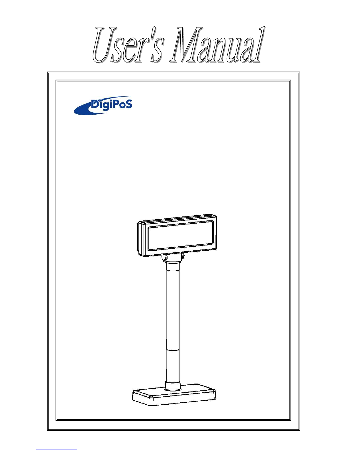
Vacuum Fluorescent
Customer Display
Model: WD-2030 XXXX
Version: 1.2
Page 2

WD-2030 XXXX customer display
1
INDEX
1. FEATURES ......................................................................................................... 3
2. GENERAL SPECIFICATIONS ......................................................................... 4
3. UNPACKING AND CHECKING THE PARTS ................................................ 5
3.1 P
ARTS LIST (WITH BASE
PCB) .......................................................................... 5
3.2 P
ARTS LIST (WITHOUT BASE
PCB) .................................................................... 6
3.3 M
ODEL NUMBER
............................................................................................... 7
4. DISPLAY MODULE INTERFACE ................................................................... 8
4.1 RS232 S
PECIFICATIONS
..................................................................................... 8
4.1.1 RS232 connector to PCB (CN1) .................................................................. 8
4.1.2 RS232 connector to PCB (CN6) .................................................................. 9
4.1.3 RS232 connector to PCB (CN7) ................................................................ 10
4.2 USB
SPECIFICATIONS
...................................................................................... 10
4.2.1 USB connector to PCB (CN2) ................................................................... 10
4.3 P
OWER
USB
SPECIFICATIONS
........................................................................... 11
4.3.1 USB Connector to PCB (CN2+CN9) ........................................................ 11
5. BASE PCB INTERFACE ................................................................................. 12
5.1 RS-232 I
NTERFACE CONNECTOR (ON THE BOTTOM OF THE BASE SECTION
) ........ 12
5.2 P
OWER SUPPLY CONNECTORS
.......................................................................... 12
5.2.1 CN2 / Type: DC jack (5.5/2.1) .................................................................. 12
5.2.2 CN1,CN6 / Type: Miniature jacks quick lock 3 pin ................................... 12
5.3 CN5 / T
YPE:
DB25/F
TOGETHER WITH SIGNALS OF
RS-232C ............................ 12
5.4 RS232C
LINK TO
PC/HOST
CONNECTOR
(CN5) ............................................... 13
5.5 RS232C
LINK TO PRINTER CONNECTOR
(CN3) .................................................. 13
5.6 RS232C
LINK TO DISPLAY PANEL
(CN4) .......................................................... 13
6. USB BASE INTERFACE ................................................................................. 14
6.1 USB I
NTERFACE CONNECTOR (ON THE BUTTOM OF THE BASE SECTION
) ............. 14
6.2 P
OWER SUPPLY CONNECTORS
.......................................................................... 14
6.2.1 CN1,CN6 / Type: Miniature jacks quick lock 3 pin ................................... 14
6.2.2 CN2 / Type: DC jack (5.5/2.1) .................................................................. 14
6.3 USB
INPUT PORT LINK TO
PC/HOST USB
CONNECTOR
(CN5) .......................... 15
6.4 RS232C
LINK TO PRINTER CONNECTOR
(CN3) .................................................. 15
6.5 RS232C
LINK TO DISPLAY PANNEL
(CN4) ........................................................ 15
7. DIP SWITCH SETTING .................................................................................. 16
7.1 C
OMMAND TYPE SELECTION
............................................................................ 16
7.2 B
AUD RATE SELECTION
.................................................................................... 16
7.3 P
ARITY CHECK SELECTION
............................................................................... 16
7.4
INTERNATIONAL CHARACTER SET SELECTION
................................................... 17
7.5 S
ELF-TEST & DEMO FUNCTION SELECTION
........................................................ 17
8. COMMAND ...................................................................................................... 18
Page 3

WD-2030 XXXX customer display
2
8.1 CD5220 S
TANDARD MODE COMMAND LIST
..................................................... 18
8.2 UTC
STANDARD MODE COMMAND LIST
............................................................ 21
8.3 UTC
ENHANCED MODE COMMAND LIST
............................................................ 22
8.4 AEDEX
MODE COMMAND LIST
........................................................................ 23
8.5 PD3000
MODE COMMAND LIST
........................................................................ 23
8.6 ADM788
MODE COMMAND LIST
...................................................................... 24
8.7 DSP-800
MODE COMMAND LIST
....................................................................... 25
8.8 EPSON ESC/
POS COMMAND LIST
..................................................................... 27
9. CHARACTER SET .......................................................................................... 30
9.1 USA,
STANDARD CHARACTER SET
(20H – 7EH) ................................................. 30
9.2 I
NTERNATIONAL CHARACTER SETS
.................................................................. 31
9.3 P
AGE 0
(PC437: USA, S
TANDARD EUROPE)
(80H – FFH) ................................ 32
9.4 P
AGE 1 (KATAKANA)
(80H – FFH) .................................................................. 33
9.5 P
AGE 2
(PC850: M
ULTILINGUAL)
(80H – FFH) ................................................ 34
9.6 P
AGE 3
(PC860: P
ORTUGUESE)
(80H – FFH) ................................................... 35
9.7 P
AGE 4
(PC863: C
ANADIAN-FRENCH)
(80H – FFH) ......................................... 36
9.8 P
AGE 5
(PC865: N
ORDIC)
(80H – FFH) ........................................................... 37
9.9 P
AGE 6 (SLAVONIC)
(80H – FFH) .................................................................... 38
9.10 P
AGE 7 (RUSSIA)
(80H – FFH) ...................................................................... 39
9.11 P
AGE 19
(PC858 E
URO)
(80H – FFH) ............................................................ 40
9.12 P
AGE 12 (GREEK)
(80H – FFH) ..................................................................... 41
9.13 P
AGE 26
(WPC-1257) (80H – FFH) ............................................................... 42
APPENDIX A: DISPLAY WITH RECTANGLE BASE DIMENSION .............. 43
APPENDIX B: DISPLAY WITH ROUND BASE DIMENSION ........................ 43
APPENDIX C: RECTANGLE BASE DIMENSION ........................................... 44
APPENDIX D: ROUND BASE DIMENSION ..................................................... 44
APPENDIX E: TUBE DIMENSION .................................................................... 45
APPENDIX F: PASS THROUGH INSTALLATION GUIDE ............................ 47
Page 4

WD-2030 XXXX customer display
3
1. FEATURES
1. Data can be displayed on 20 columns x 2 lines.
2. Blue-green color and large character are easy to eye.
3. The display panel is adjustable to provide the best view angle.
4. Provide 2 poles for base position installation.
5. The DIP-switches setting emulate commands mode, baud rate and
international characters.
6. CD5220/UTC/EMAX/ADM/EscPOS/DSP-800 emulation command sets.
7. Characters can be defined by user-defined character commands. (For
Esc/POS/CD5220/DSP 800 command).
8. Provides an interface based on USB emulation RS-232C, baud rate
4,800, 9,600, 19,200 and 115,200 bps.
9. The VFD customer display and printer can be connected by
pass-through (ref. Appendix F).
10. Various power connectors and wide range power input (5VDC or
9~45VDC).
Page 5
WD-2030 XXXX customer display
4
2. GENERAL SPECIFICATIONS
NO ITEM Descriptions
1 Display method Vacuum fluorescent display
2 Number of character 20 columns x 2 lines
3 Character font 5 x 7 Dot matrix
4 Display color Blue green
5 Brightness 700 cd/ m2
6 Fonts
96 alphanumeric
13 kinds of international character sets
1 kind of user define character set
7 Character size 9.03 mm x 5. 25 mm
8 Power supply 5VDC or 9~ 45VDC
9 Power consumption 6 W (Max.)
10 MTBF 30,000 hours (power on time)
11 Panel dimensions 224 (W) x 93 (H) x 50(D) mm
12 External dimensions
Long 225(W) x 100(D) 500(H)mm
Middle 225(W) x 100(D) 281(H)mm
Short 225(W) x 100(D) 193(H)mm
13 Viewing angle (Horizontal) 120 degrees
14 Viewing angle (Vertical) 90 degrees
15 Rotation angle (Horizontal) 350 degrees
16 Tilt angle 0 ~ 60 degrees
17 Weight 1.25 Kg
18 Operating temperature
0 ~ 45℃
19 Operating Humidity 10%~90%
20 Storage Temperature
-10 ~ 50℃
21 Storage Humidity 10%~90%
Table 2-1
Page 6
WD-2030 XXXX customer display
5
3. UNPACKING AND CHECKING THE PARTS
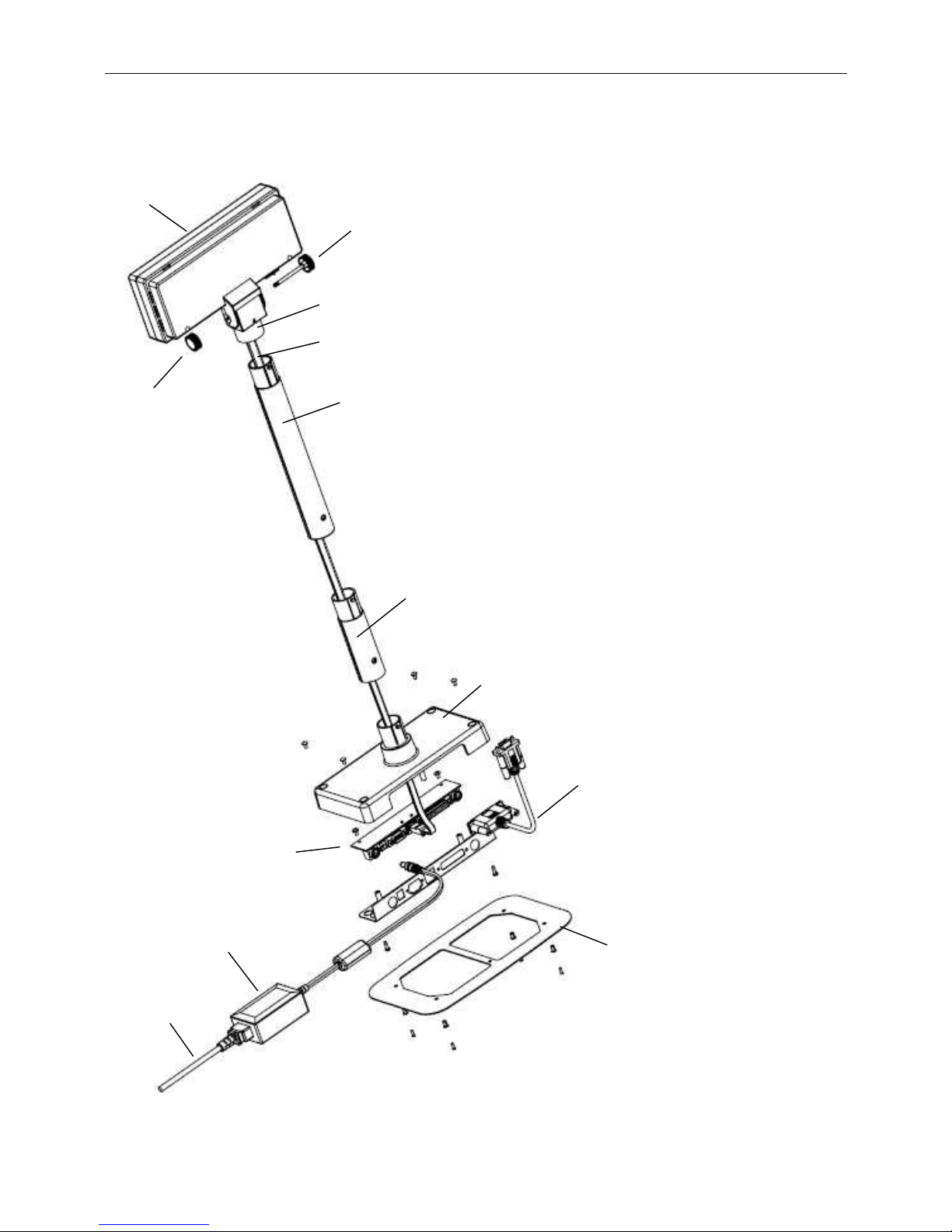
3.1 Parts list (With Base PCB)
(1) D
isplay Module.
(2) Nut.
(3) Knob.
(4) Neck.
(5) Display Cable.
(6) Long Pole
(7) Short Pole
(8) Base Housing.
(9) Base PCB.
(10) Power Adapter
(11) AC Cord
(12) Signal transmission line.
(13) Plate.
(1)
(2)
(3)
(4)
(5)
(6)
(7)
(8)
(12)
(13)
(11)
(10)
(9)
Page 7
WD-2030 XXXX customer display
6
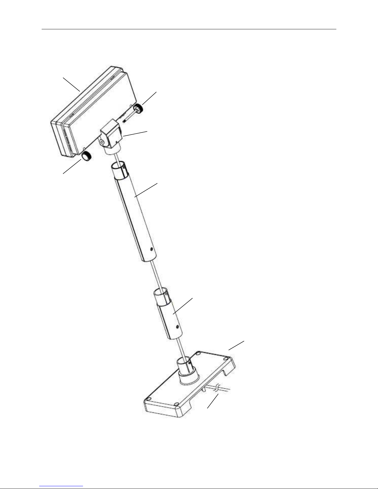
3.2 Parts list (Without Base PCB)
(1) D
isplay Module.
(2) Nut.
(3) Knob.
(4) Neck.
(5) Long Pole
(6) Short Pole
(7) Base Housing.
(8) Signal transmission line.
(1)
(8)
(6)
(5)
(4)
(3)
(2)
(7)
Page 8
WD-2030 XXXX customer display
7
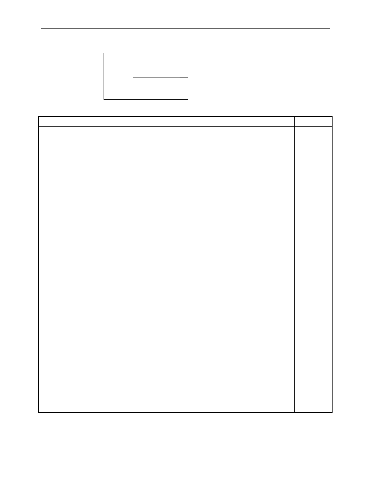
3.3 Model Number
WD-2030 X X X X
1 2 3 4
I
nterface
(Display Module)
Base Type Power Input Color
R:RS-
232 12V
S:RS-232 5V
U:USB
O:Power USB 5V
P:Power USB 12V
Q:Power USB 24V
R:RS-
232 Base
U:USB-B Base
H:HUSB Base
S:Only Rectangular
Base Housing
C:Only Circular
Base Housing
N:No Base
M:Module + Neck
A:
USA Cord + SPS
B:Jap.Cord + SPS
C:Eur. Cord + SPS
D:U.K Cord + SPS
E:Fra. Cord + SPS
F:Asu.Cord + SPS
G:SA. Cord + SPS
Y:No AC Cord + SPS
H:USA Cord + IEC
I:Jap.Cord + IEC
J:Eur. Cord + IEC
K:U.K Cord + IEC
L:Fra. Cord + IEC
M:Asu.Cord + IEC
N:SA. Cord + IEC
Z:No AC Cord + IEC
W:No AC Cord + No Power
1:USA Adaptor
2:Jap. Adaptor
3:Eur. Adaptor
4:U.K Adaptor
5:Fra. Adaptor
6:Asu. Adaptor
7:SA. Adaptor
O:Power USB 5V
P:Power USB 12V
Q:Power USB 24V
R:RS-232 Port(PC)
S:RS-232 DC Jack + No Power
U:USB Port(PC)
V:USB Plug (POWER SUPPY)
B:
Black
W:
White
Table 3-2
1
2
3
4
Page 9
WD-2030 XXXX customer display
8
4. Display Module Interface
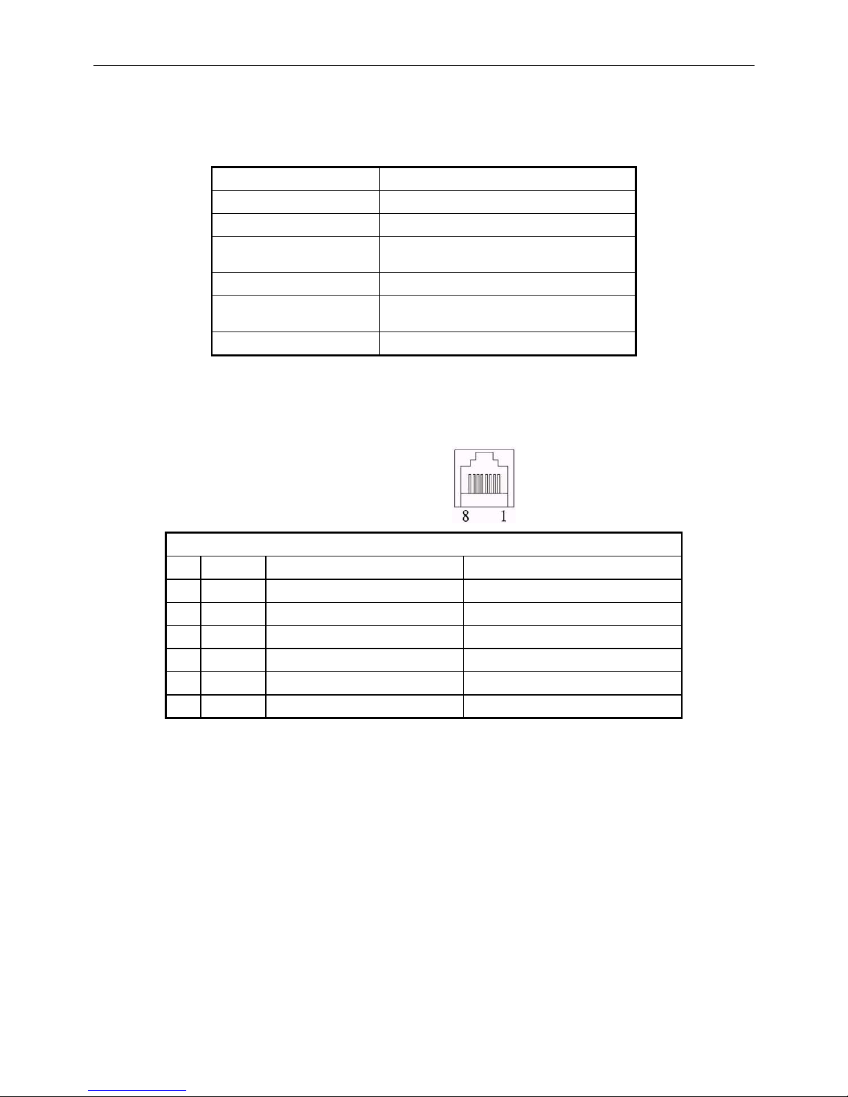
4.1 RS232 Specifications
Data transmission: Serial
Synchronization: Asynchronous
Handshaking: DTR / DSR
Signal level:
MARK =
-
3 to
–
15 V (logic “1”)
SPACE = +3 to +15 V (logic “0”)
Baud rates: 4800,9600,19200 or 115200 bps
Parity and bit length
None parity, 8 data bits or
Even parity, 7 data bits
Stop bits: 1 or more
Table 4-1
4.1.1 RS232 connector to PCB (CN1)
Type: RJ45/8P/8C
Pin assignment
No Signal Direction Function description
1,2 Vin - Power 5VDC or 9~45 VDC
3,4 GND - Signal ground
5 CTS From Printer to Display Printer ready signal
6 RTS From Display to PC/Host Display/Printer ready signal
7 RXD From PC/Host to Display Display/Printing data signal
8 TXD From Display to Printer Printer status data signal
Table 4-2
Page 10
WD-2030 XXXX customer display
9
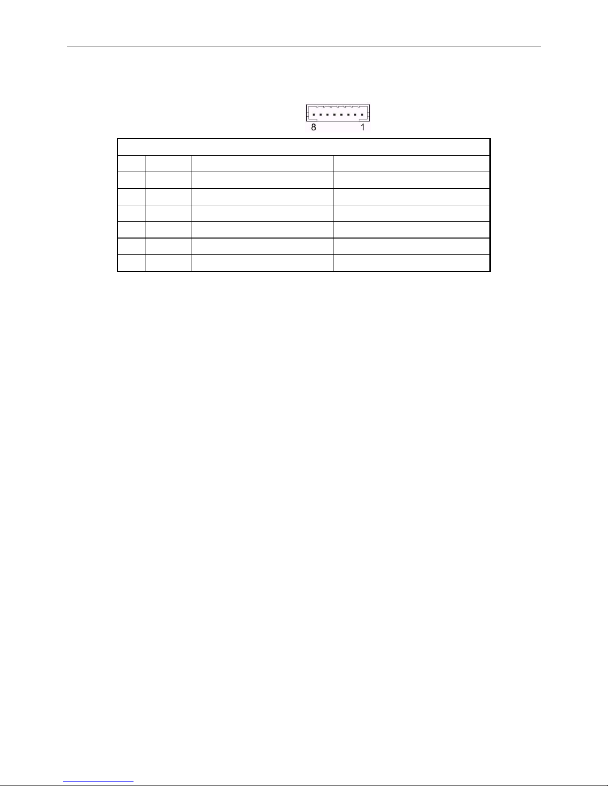
4.1.2 RS232 connector to PCB (CN6)
Type: PH 2.0 mm/8P
Pin assignment
No Signal Direction Function description
1,2
Vin - Power 5VDC or 9~45 VDC
3,4 GND - Signal ground
5 CTS From Printer to Display Printer ready signal
6 RTS From Display to PC/Host Display/Printer ready signal
7 RXD From PC/Host to Display Display/Printing data signal
8 TXD From Display to Printer Printer status data signal
Table 4-3
Page 11
WD-2030 XXXX customer display
10
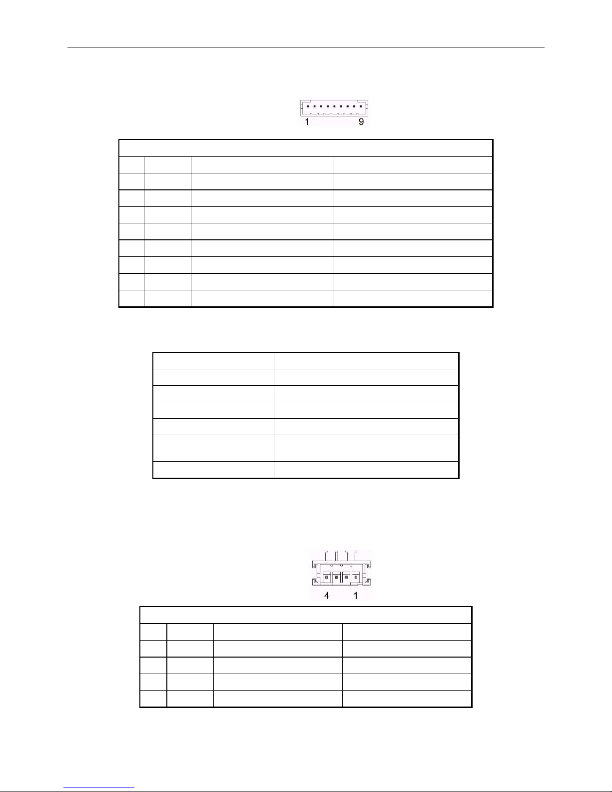
4.1.3 RS232 connector to PCB (CN7)
Type: PH 2.0 mm/9P
Pin assignment
No Signal Direction Function description
1 NC - 2 TXD From Display to Printer Printer status data signal
3 RXD From PC/Host to Display Display/Printing data signal
4 CTS From Printer to Display Printer ready signal
5 GND - Signal ground
6,8 RTS From Display to PC/Host Display/Printer ready signal
7 NC - 9 Vin - Power 5VDC or 9 ~ 45 VDC
Table 4-4
4.2 USB specifications
Data transmission: USB emulation RS232C
Synchronization: Asynchronous
Handshaking: DTR / DSR
Signal level: 0~+3V
Baud rates: 4800,9600,19200 or 115200 bps
Parity and bit length
None parity, 8 data bits or
Even parity, 7 data bits
Stop bits: 1 or more
Table 4-5
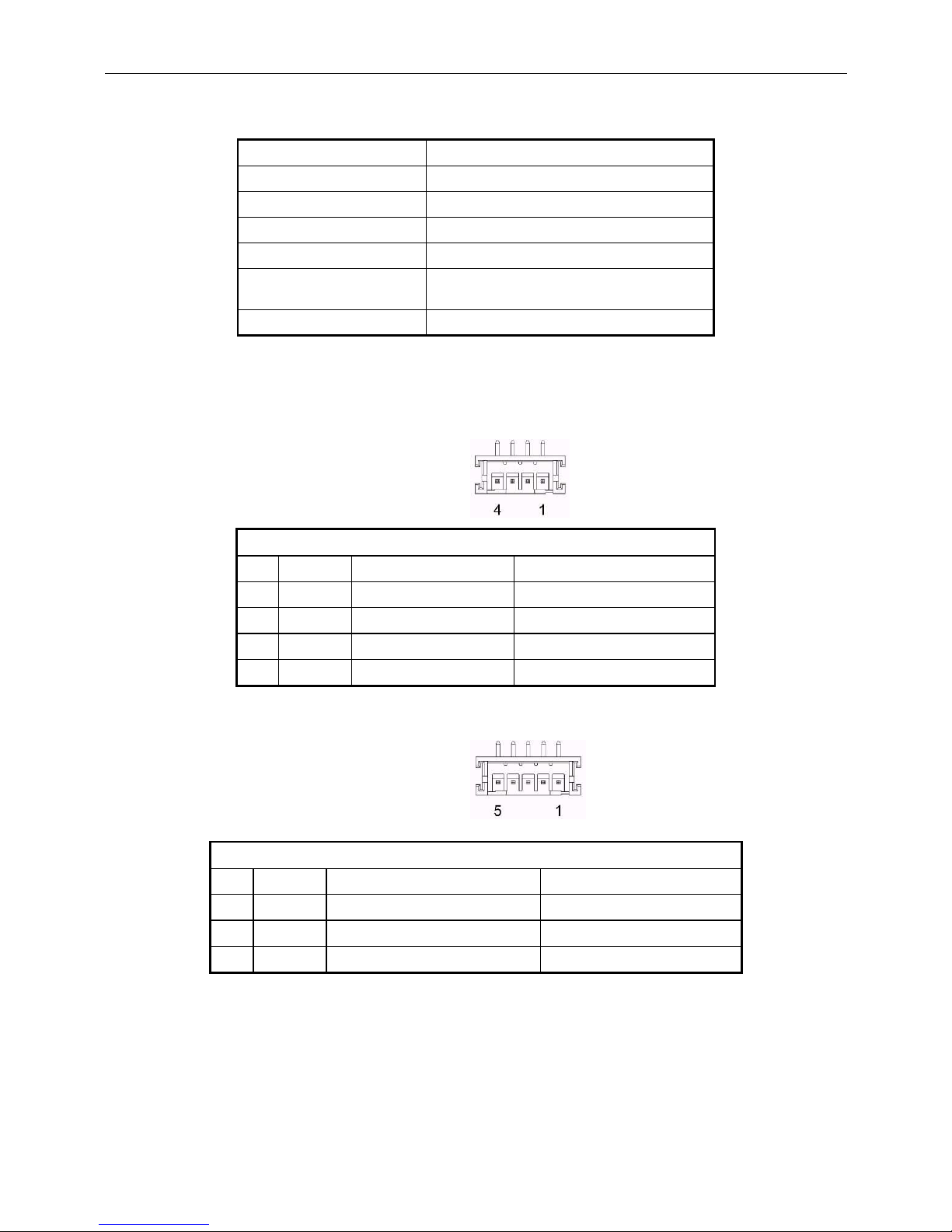
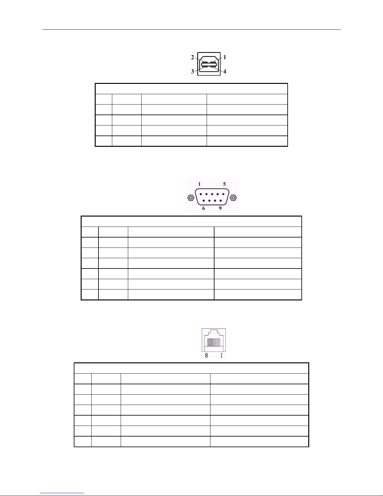
4.2.1 USB connector to PCB (CN2)
Type: WAFER PH 2.0mm 4P
Pin assi
gn
men
t
No Signal
Direction
Function de
scription
1 V+
5V From PC/Host USB power 5 VDC
2 D-
Data signal -
3 D+
Data signal+
4 GND
Signal ground
Table 4-6
Page 12
WD-2030 XXXX customer display
11
4.3 Power USB specifications
Data transmission: USB emulation RS232C
Synchronization: Asynchronous
Handshaking: DTR / DSR
Signal level: 0~+3V
Baud rates: 4800,9600,19200 or 115200 bps
Parity and bit length
None parity, 8 data bits or
Even parity, 7 data bits
Stop bits: 1 or more
Table 4-7
4.3.1 USB Connector to PCB (CN2+CN9)
CN2
Type: WAFER PH 2.0mm 4P
Pin assi
gn
men
t
No Signal
Direction
Function description
1 V+
5V From PC/Host USB power 5 VDC
2 D-
Data signal -
3 D+
Data signal+
4 GND
Signal ground
Table 4-8
CN9
Type: WAFER PH 2.0mm 5P
Pin assi
gn
men
t
No Sign
al Direction
Function description
2,3 V+
5/12/24V From PC/Host VPLUS
1,4 GND
PWR Ground Signal ground
5 FG
Data signal+
Table 4-9
Page 13
WD-2030 XXXX customer display
12
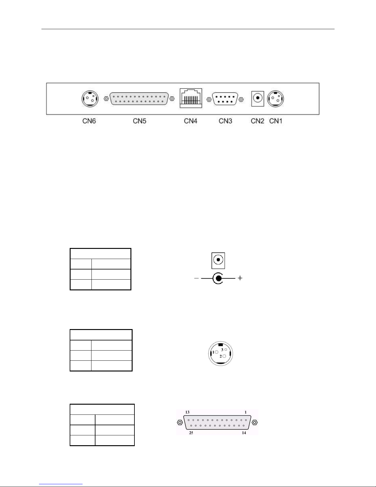
5. Base PCB Interface
5.1 RS-232 Interface connector (On the bottom of the base
section)
CN1,CN6: 24VDC power supply pass-through connects
CN2: Power input connector from adapter
CN3: RS-232C connect to printer
CN4: Connect to display panel
CN5: RS-232C connect to PC/Host
5.2 Power Supply Connectors
The variable power input which are available on base connectors, but only
if one connector can be selected for power input, the description as below:
5.2.1 CN2 / Type: DC jack (5.5/2.1)
Pin assignmen
t
No Signal
+ Vin1
- GND
Table 5-1
5.2.2 CN1,CN6 / Type: Miniature jacks quick lock 3 pin
Table 5-2
5.3 CN5 / Type: DB25/F together with signals of RS-232C
Table 5-3
Pin assignmen
t
No Sig
nal
1 Vin2
2 GND
Pin assignment
No Signal
16,25
Vin3
7 GND
Page 14
WD-2030 XXXX customer display
13
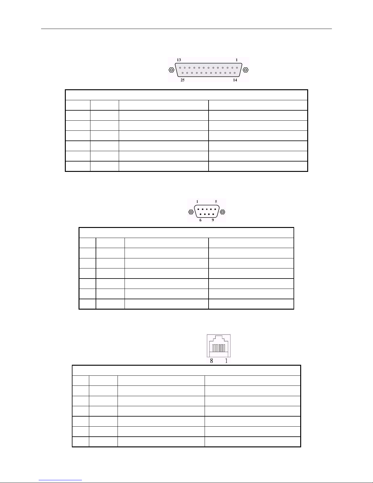
5.4 RS232C link to PC/HOST connector (CN5)
Type: DB25/F
Pin assignment
No Signal
Direction
Function description
2 TXD
From printer to PC/Host
Printer status data
3 RXD
From PC/Host to display
Receive data
4,20
DTR
From display to PC/Host
Display/printer ready signal
6 DSR
From PC/Host to printer
PC/Host ready signal
7 GND
-
Signal g
r
ound
16,25
Vin3
From PC/Host to display
Power input
Table 5-4
5.5 RS232C link to printer connector (CN3)
Type: DB9/M
Pin assignment
No Signal Direction Function description
2 RXD From printer to PC/Host Printer status data
3 TXD From display to printer Printing data
5 GND - Signal ground
4,7 DTR From PC/Host to printer PC/Host ready signal
6 DSR From printer to display Printer ready signal
9 Vin2 From Hosiden to printer Power through to printer
Table 5-5
5.6 RS232C link to display panel (CN4)
Type: RJ45/8P/8C
Pin assignment
No Signal Direction Function description
1,2
Vin - Power 5VDC or 9~45 VDC
3,4 GND - Signal ground
5 DSR From Printer to Display Printer ready signal
6 DTR From Display to PC/Host Display/Printer ready signal
7 RXD From PC/Host to Display Display/Printing data signal
8 TXD From Display to Printer Printer status data signal
Table 5-6
Page 15
WD-2030 XXXX customer display
14
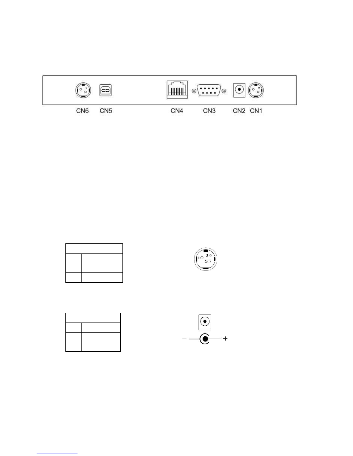
6. USB BASE INTERFACE
6.1 USB Interface connector (On the buttom of the base
section)
CN1,CN6: 24VDC power supply pass-through connects
CN2: Power input connector from adapter
CN3: RS-232C connect to printer
CN4: Connect to display panel
CN5: USB input
6.2 Power Supply Connectors
There are variable power inputs which are available on base connector,
but only one connector can be selected for power input function, the
description as below:
6.2.1 CN1,CN6 / Type: Miniature jacks quick lock 3 pin
Pin assignment
No Signal
1 Vin2
2 GND
Table 6-1
6.2.2 CN2 / Type: DC jack (5.5/2.1)
Pin assignment
No Signal
+ Vin1
- GND
Table 6-2
Page 16
WD-2030 XXXX customer display
15
6.3 USB input port link to PC/HOST USB connector (CN5)
Type: USB
Pin assignment
No Signal
Direction
Function description
1 V+ 5V From PC/Host
USB power 5 V
DC
2 D- Data signal
-
3 D+ Data signal
+
4 GND
-
Signal g
r
ound
Table 6-3
6.4 RS232C link to printer connector (CN3)
Type: DB9/M
Pin assignment
No Signal Direction Function description
2 RXD From printer to PC/Host Printer status data
3 TXD From display to printer Printing data
5 GND - Signal ground
4,7 DTR From PC/Host to printer PC/Host ready signal
6 DSR From printer to display Printer ready signal
9 Vin2 From Hosiden to printer Power through to printer
Table 6-4
6.5 RS232C link to display pannel (CN4)
Type: RJ45/8P/8C
Pin assignment
No Signal Direction Function description
1,2
Vin - Power 5VDC or 9~45 VDC
3,4 GND - Signal ground
5 DSR From Printer to Display Printer ready signal
6 DTR From Display to PC/Host Display/Printer ready signal
7 RXD From PC/Host to Display Display/Printing data signal
8 TXD From Display to Printer Printer status data signal
Table 6-5
Page 17
WD-2030 XXXX customer display
16
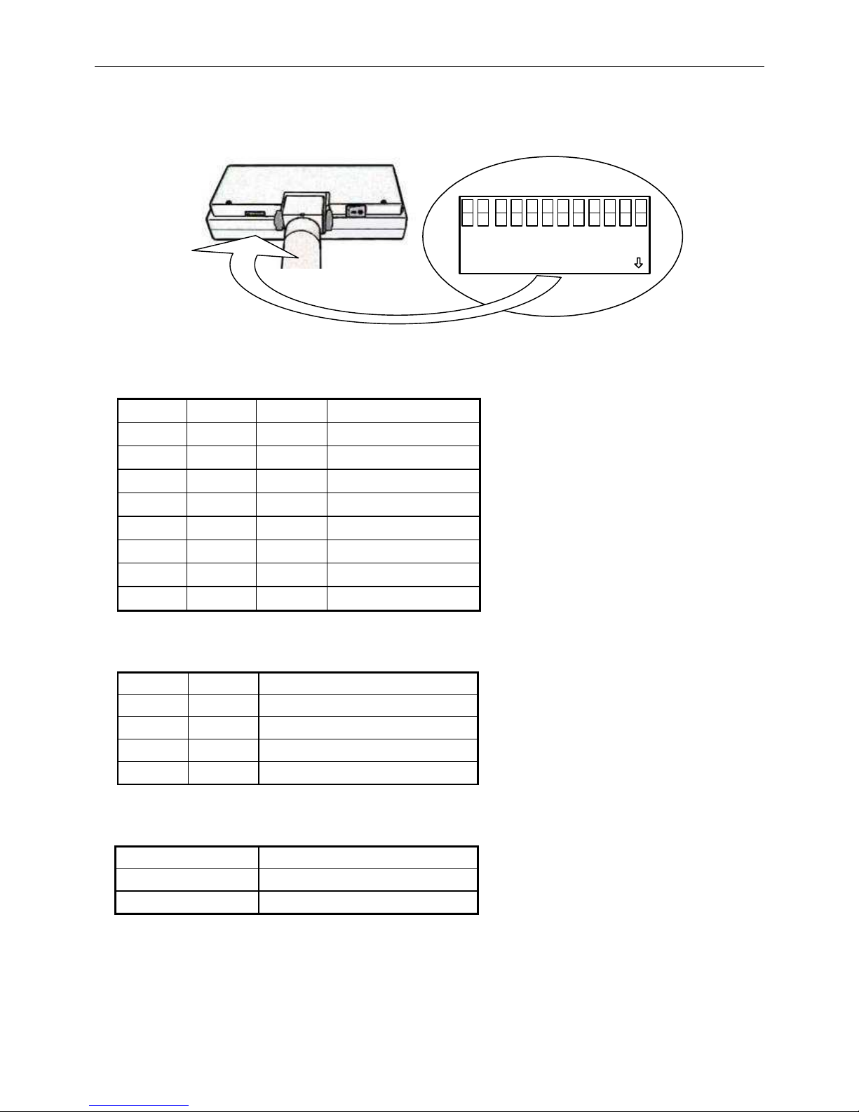
7. DIP SWITCH SETTING
7.1 Command type selection
SW1 SW2 SW3 Command type
ON ON ON DSP800
OFF ON ON ESC/pos
ON OFF ON PD3000
OFF OFF ON ADM 788
ON ON OFF EMAX(Aedex)
OFF ON OFF UTC/P
ON OFF OFF UTC/S
OFF OFF OFF CD5220
Table 7-1
7.2 Baud rate selection
SW8 SW9 Baud rate (bps)
ON ON 4800
OFF ON 9600
ON OFF 19200
OFF OFF 115200
Table 7-2
7.3 Parity check selection
SW10 Parity & data bits
ON None-parity , 8 data bits
OFF Even-parity , 7 data bits
Table 7-3
ON
1 2 3 4 5 6 7 8 9
10 11 12
DIP
Page 18
WD-2030 XXXX customer display
17
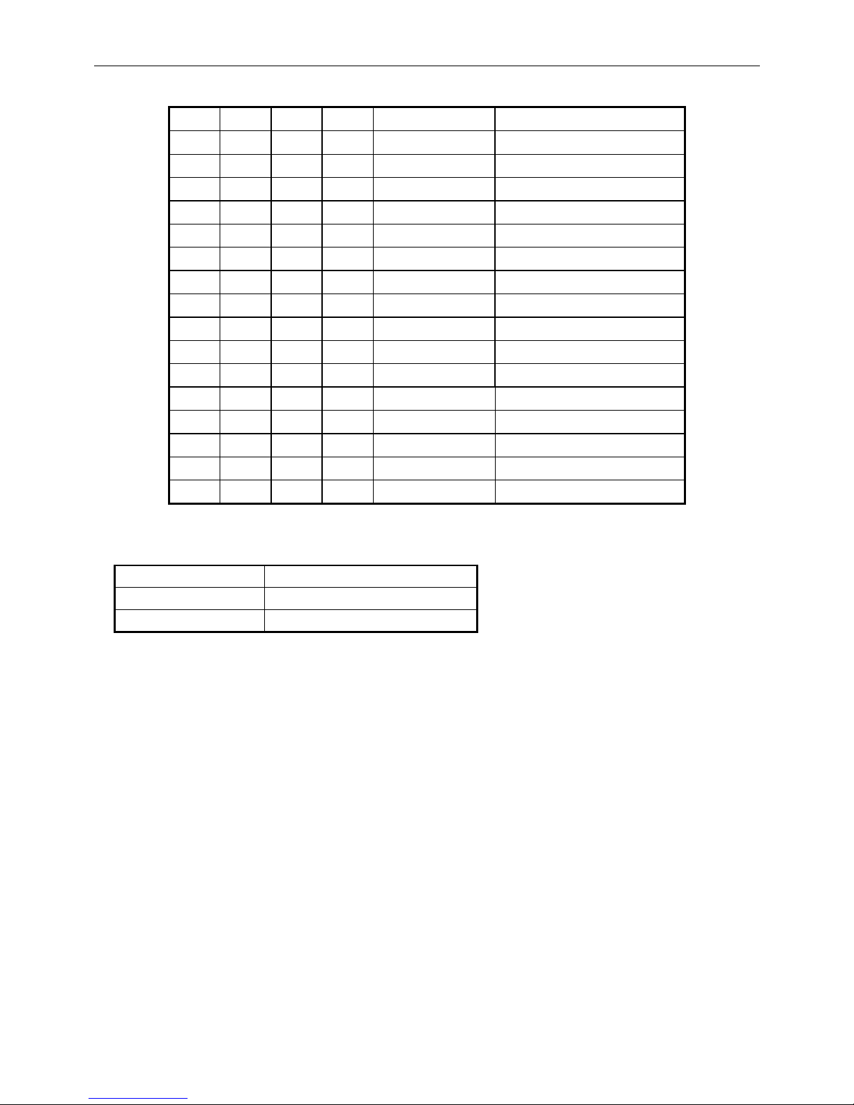
7.4 International character set selection
SW4 SW5 SW6 SW7 Character set Code table ( 80H-FFH)
ON ON ON ON U.S.A. PC-437(USA&Europe)
OFF ON ON ON France PC-858(Euro)
ON OFF ON ON Germany PC-858(Euro)
OFF OFF ON ON U.K. PC-858(Euro)
ON ON OFF ON Denmark I PC-858(Euro)
OFF ON OFF ON Sweden PC-858(Euro)
ON OFF OFF ON Italy PC-858(Euro)
OFF OFF OFF ON Spain PC-858(Euro)
ON ON ON OFF Japan Katakana
OFF ON ON OFF Norway PC-858(Euro)
ON OFF ON OFF Denmark II PC-858(Euro)
OFF OFF ON OFF U.S.A Slavonic
ON ON OFF OFF U.S.A Russia
OFF ON OFF OFF U.S.A PC860 (Portuguese)
ON OFF OFF OFF U.K. Greek
OFF OFF OFF OFF U.S.A WPC1257
Table 7-4
7.5 Self-test & demo function selection
SW11 Function
ON Enable
OFF Disable
Table 7-5
* SW12 reserve
Page 19
WD-2030 XXXX customer display
18
8. COMMAND
8.1 CD5220 Standard Mode Command List
Command Code (hex) Function description
ESC DC1 1B 11 Overwrite mode
ESC DC2 1B 12 Vertical scroll mode
ESC DC3 1B 13 Horizontal scroll mode
ESC QA ....CR
1B 51 41 data x m 0D
Set the string
display mode,writed string to
upper line
m ≦ 20
ESC QB ....CR 1B 51 42 data x m 0D
Set the string display mode, writed string to
lower line
m ≦ 20
ESC QD ....CR 1B 51 44 data x m 0D
Upper line message scroll continuously
m ≦ 40
ESC [ D 1B 5B 44 Move cursor left
BS 08 Move cursor left
ESC [ C 1B 5B 43 Move cursor right
HT 09 Move cursor right
ESC [ A 1B 5B 41 Move cursor up
ESC [ B 1B 5B 42 Move cursor down
LF 0A Move cursor down
ESC [ H 1B 5B 48 Move cursor to home position
HOM 0B Move cursor to home position
ESC [ L 1B 5B 4C Move cursor to left-most position
CR 0D Move cursor to left-most position
ESC [ R 1B 5B 52 Move cursor to right-most position
ESC [ K 1B 5B 4B Move cursor to bottom position
ESC l x y 1B 6C x y
Move cursor to specified position
1 ≦x≦ 20 ,row position
1 ≦y≦ 2 ,column position
Page 20
WD-2030 XXXX customer display
19
Command Code (hex) Function description
ESC @ 1B 40 Initialize display
CLR 0C Clear display screen , and clear string mode
CAN 18 Clear cursor line, and clear string mode
ESC * n
1B 2A n
Brightness adjustment
1≦n≦4
ESC & s n m
[a (P1..pa)]x
(m-n+1)
1B 26 1 n m [a(p1..pa)]
x (m-n+1)
Define download characters.
32 ≦ n ≦ m 255
1 ≦a ≦ 5
p1..p5 =row1..row5
ESC ? n 1B 3F n
Deletes download characters.
32 ≦ n ≦ m 255
ESC % n 1B 25 n
Select/cancel download character set.
n = 0 , Cancel
n = 1 , Select
ESC _ n 1B 5F n
Set cursor on/off
n = 1 , cursor on
n = 2 , cursor off
ESC f n 1B 66 n Select international fonts set, refer *2
ESC c n 1B 63 n Select code, refer *3
ESC = n 1B 3D n
Select peripheral device, display or printer
n bit 0 = 1 select printer
n bit 1 = 1 select display
Table 8-1
Page 21
WD-2030 XXXX customer display
20
*
2: The parameter of international fonts set control by command “ESC f n”
Parameter “n” International Font Set
“A” U.S.A.
“G” Germany
“I” Italy
“J” Japan
“U” U.K.
“F” France
“S” Spain
“N” Norway
“W” Sweden
“D” Denmark I
“E” Denmark II
“L” Slavonic
“R” Russia
Table 8-2
*3: The parameter of the code table control by command “ESC c n”
Parameter “n”
International font set
“A” Compliance with ASCII code
“J” Compliance with JIS code
“L” Compliance with SLAVONIC code
“R” Compliance with RUSSIA code
Table 8-3
Page 22
WD-2030 XXXX customer display
21
8.2 UTC standard mode command list
Command Code (hex) Function description
EOT n 04 n
Display Dimming
n = 20h, 40h, 60h, FFh
BS 08 Back space
HT 09 Horizontal tab
LF 0A Line feed
CR 0D Carriage return
DLE 0F Display position
DC1 11 Over write display mode
DC2 12 Vertical scroll mode
DC3 13 Cursor on
DC4 14 Cursor off
CAN 18 Clear to end of line
EM 19 Clear to end of display
FS 1C Flashing text start
GS 1D Flashing text end
US 1F Reset display
RS 1E Home and clear display
ESC d 1B 64 Change to UTC enhanced mode
Table 8-4
Page 23
WD-2030 XXXX customer display
22
8.3 UTC enhanced mode command list
Command Code (hex) Function description
SI 0F Flashing text start
SO 0E Flashing text stop
ESC u A ..CR 1B 75 41 data x m 0D
Upper line display
0 ≦ m ≦ 20
ESC u B ..CR 1B 75 42 data x m 0D
Bottom line display
0 ≦ m ≦ 20
ESC u D ..CR 1B 75 44 data x m 0D
Upper line message scroll continuously
0 ≦ m ≦40
ESC u E ..CR 1B 75 45 “hh:mm” 0D
Display time
’00’ ≦ hh ≦ ‘23’
’00’ ≦ mm ≦ ‘59’
ESC u F ..CR 1B 75 46 data x m 0D Upper line message scroll once pass
ESC u H ..CR 1B 75 48 n m 0D
Change attention code
32 ≦ n ≦ 255
32 ≦ m ≦ 255
ESC u I ..CR 1B 75 49 data x m 0D
Two line display
0 ≦ m ≦ 40
ESC RS CR 1B 0F 0D Change to UTC standard mode
Table 8-5
Page 24
WD-2030 XXXX customer display
23
8.4 AEDEX mode command list
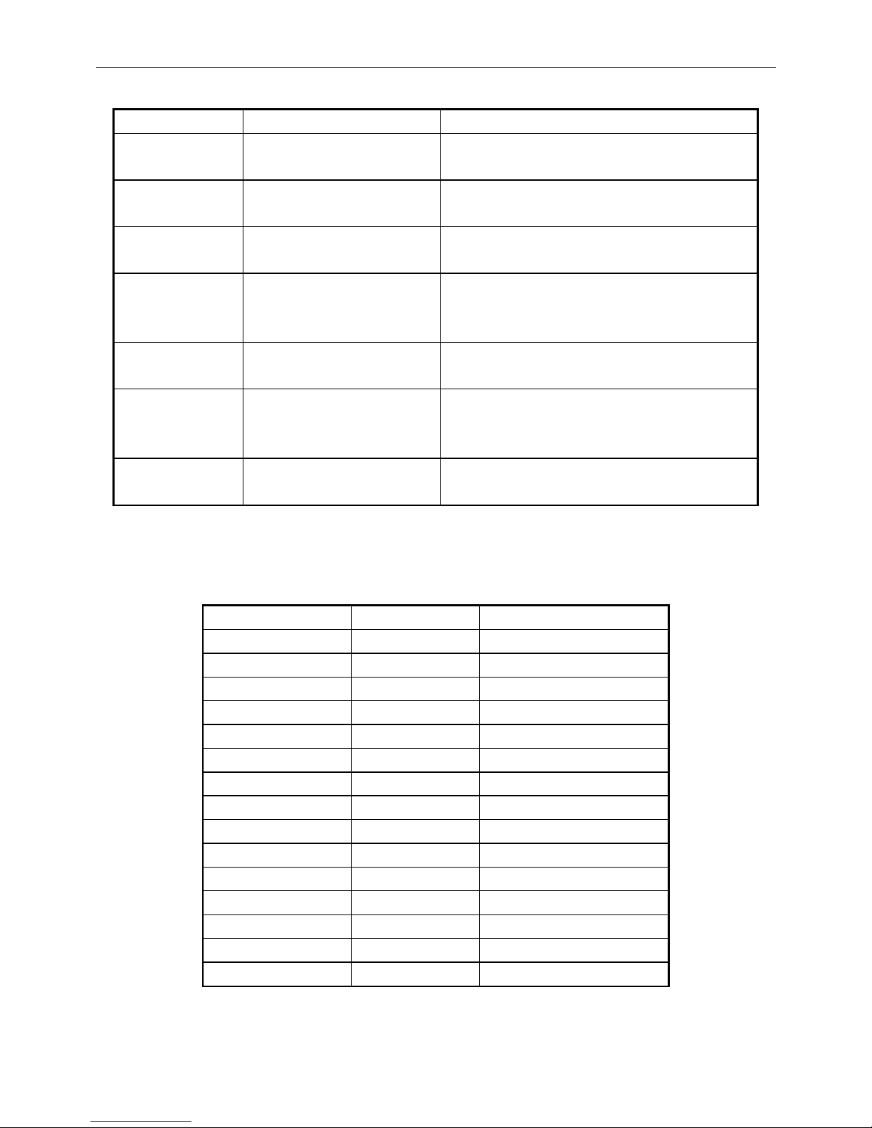
Command Code (hex) Function description
! # 1 ....CR 21 23 31 data x m 0D
Upper line display
0 ≦ m ≦ 40
! # 2 ....CR 21 23 32 data x m 0D
Bottom line display
0 ≦ m ≦ 40
! # 4 ....CR 21 23 34 data x m 0D
Upper line message scroll continuously
0 ≦ m ≦ 40
! # 5 ....CR 21 23 35 “hh:mm” 0D
Display time
‘00’ ≦ hh ≦ ‘23’
’00’ ≦ mm ≦ ‘59’
! # 6 ....CR 21 23 36 data x m 0D
Upper line message scroll one pass
0 ≦ m ≦ 40
! # 8 ....CR 21 23 38 n m 0D
Change attention code
32 ≦n ≦255
32 ≦ m ≦ 255
! # 9 ....CR 21 23 39 data x m 0D
Two line display
0 ≦ m ≦ 40
Table 8-6
8.5 PD3000 mode command list
Command Code (hex) Function description
DC2 12 Vertical Scroll Mode
DC1 11 Normal Display Mode
EOT 04 Brightness Control
BS 08 Back Space
HT 09 Horizontal Tab
LF 0A Line Feed
CR 0D Carriage Return
DLE 10 Digit Select
DC3 13 Cursor On
DC4 14 Cursor Off
US 1F Reset
ETX 03 Down Load Font
ENQ d1~d45 CR 05 d1~d45 0D Message Scroll
SOH 01 Data to Peripheral
! # STX 21 23 02 Data to Display
Table 8-7
Page 25
WD-2030 XXXX customer display
24
8.6 ADM788 mode command list
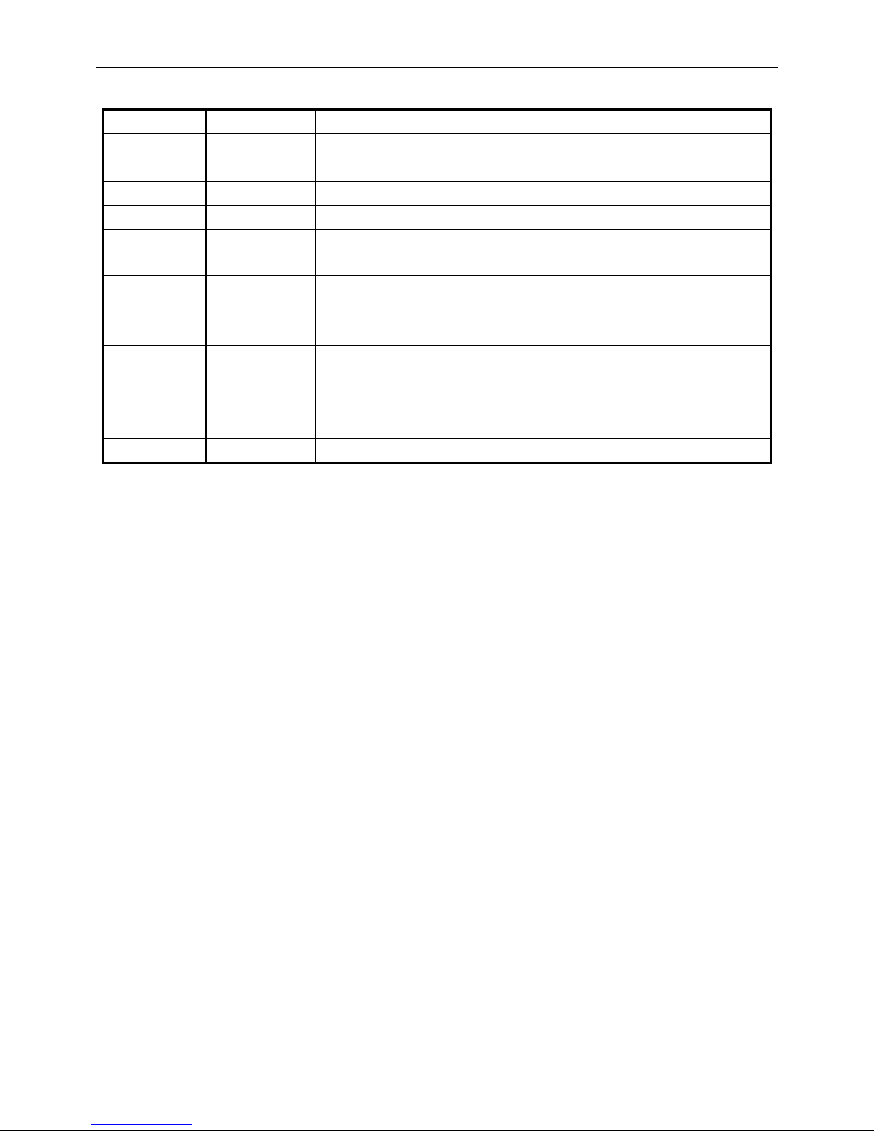
Command Code (hex) Function description
CLR 0C Clear display
CR 0D Carriage return
SLE1 0E Clear up line and move cursor to upper line left most end
SLE2 0F Clear low line and move cursor to lower line left most end
DC0 n 10 n
Set period to upper line last n position
31H ≦ n ≦ 44H
DC1 n 11 n
Set line blanking ,
n = 31H up line
n = 32H low line
DC2 n 12 n
Clear line blanking ,
n = 31H up line
n = 32H low line
SF1 1E Clear field 1 and move cursor to field 1 fast position
SF2 1F Clear field 2 and move cursor to field 2 fast position
Table 8-8
Page 26
WD-2030 XXXX customer display
25
8.7 DSP-800 mode command list
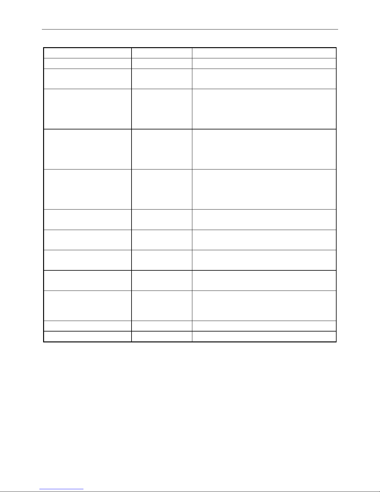
Command Code (hex) Function descriptions
EOT SOH I n ETB 04 01 49 n 17 Select international character set.
EOT SOH P n ETB 04 01 50 n 17
Move cursor to specified position.
31H ≦ n ≦ 58H
EOT SOH C n m ETB 04 01 43 n m 17
Clear display range from n position to
m position and move cursor to n
position.
31H ≦ n ≦ m ≦ 58H
EOT SOH S n ETB 04 01 53 n 17
Save the current displaying data to n
layer for demo display.
31H ≦n ≦ 33H
Refer*1
EOT SOH D n m ETB 04 01 44 n m 17
Display the saved data
31H ≦ n ≦ 37H
31H ≦ m ≦ 37H
Refer*2
EOT SOH A n ETB 04 01 41 n 17
Brightness adjustment.
31H ≦ n ≦ 34H
EOT SOH F n ETB 04 01 46 n 17
Blink display screen.
0 ≦ n ≦ 255
EOT SOH & n [px5] ETB
04 01 26 n
p1...p5 17
Define download characters
20H < n ≦ FFH
EOT SOH ? n ETB 04 01 3F n 17
Delete download characters.
20H < n ≦ FFH
EOT SOH = n ETB 04 01 3D n 17
Select peripheral device.
n = 31H,select printer
n = 32H,select display
EOT SOH % ETB 04 01 25 17 Initialize display
EOT SOH @ ETB 04 01 40 17 Execute self-test
Table 8-9
Page 27
WD-2030 XXXX customer display
26
*REMARK
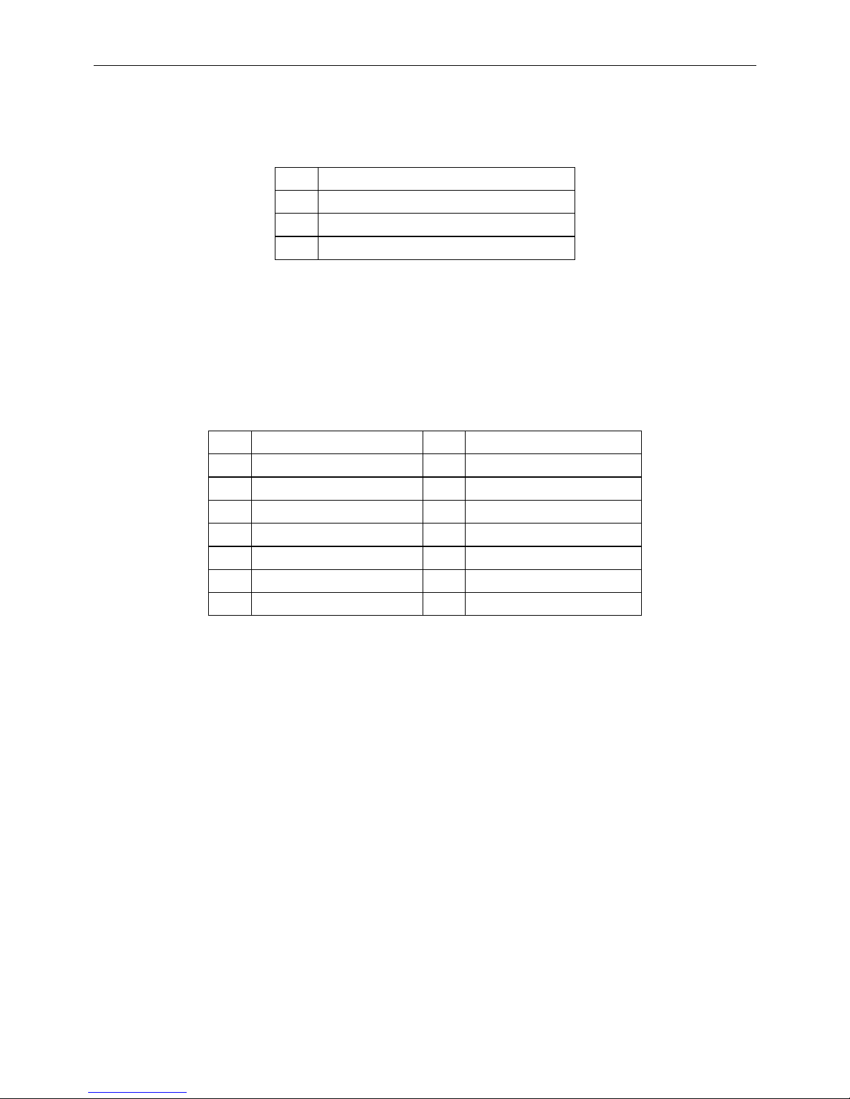
*1 Using commands “EOT SOH S n ETB”, the value (Hex) of parameter
n Layer
31h Save data in layer 1
32h Save data in layer 2
33h Save data in layer 3
Table 8-10
*2 Using commands “EOT SOH D n m ETB”, the value (Hex) of parameter. WinPOS
extended “select mode” from 33h to 37h
n Select layer m Select mode
31h Demo layer 1 31h Demo mode 1
32h Demo layer 2 32h Demo mode 2
33h Demo layer 3 33h Demo mode 3
34h Demo layer 1 + 2 34h Demo mode 1 + 2
35h Demo layer 1 + 3 35h Demo mode 1 + 3
36h Demo layer 2 + 3 36h Demo mode 2 + 3
37h Demo layer 1 + 2 + 3 37h Demo mode 1 + 2 + 3
Table 8-11
Page 28
WD-2030 XXXX customer display
27
8.8 EPSON Esc/pos command list
Command Code (hex) Function description
HT 09 Move cursor right.
BS 08 Move cursor left.
US LF 1F 0A Move cursor up.
LF 0A Move cursor down.
US CR 1F 0D Move cursor to right-most position.
CR 0D Move cursor to left-most position.
HOM 0B Move cursor to home position.
US B 1F 42 Move cursor to bottom position.
US $ x y 1F 24 x y
Move cursor to specified position.
1 ≦ x ≦ 20
1 ≦ y ≦ 2
CLR 0C Clear display screen.
CAN 18 Clear cursor line
US X n 1F 58 n
Brightness adjustment.
1 ≦ n ≦ 4
US E n 1F 45 n
Blink display screen.
0 ≦ n ≦ 255
ESC @ 1B 40 Initialize display.
ESC t n 1B 74 n
Select character code table.
0 ≦ n ≦ 7, 19, 12, 26
Refer*2
ESC R n 1B 52 n
Select international character set.
0 ≦ n ≦ 10
Refer*1
US r n 1F 72 n
Select/cancel reverse character.
0 ≦ n ≦ 1
US MD1 1F 01 Specify overwrite mode.
US MD2 1F 02 Specify vertical scroll mode.
US MD3 1F 03 Specify horizontal scroll mode.
ESC & s n m
[a(p1..pa)]x
m-n
1B 26 1 n m
[a(p1..pa)]x
m-n
Define download characters.
32 ≦ n ≦ 255
1≦ a ≦ 5
p1..p5 =row1..row5
Page 29
WD-2030 XXXX customer display
28
Command Code (hex) Function description
ESC ? 1B 3F n
Delete downloads characters.
32 ≦ n ≦ 255
ESC % 1B 25 n
Select/cancel download character set.
n = 0 , Cancel
n = 1 , Select
ESC = n
1B 3D n
Select peripheral device.
n bit 0 = 1 select printer
n bit 1 = 1 select display
US : 1F 3A Set starting/ending position of macro definition.
US ^ n m 1F 5E n m
Execute and quit macro.
0 ≦n≦255 , 0 ≦m≦255
US @ 1F 40 Execute self-test.
US T h m 1F 54 h m
Display time
0 ≦h≦23 , 0≦m≦59
US U 1F 55 Display time continuously
US C n 1F 43 n
Select / cancel cursor display
n = 1 , cursor on
n = 0 , cursor off
Table 8-12
Page 30

WD-2030 XXXX customer display
29
*REMARK
*1 Select international character set
n International font
0 U.S.A.
1 France
2 Germany
3 U.K.
4 Denmark I
5 Sweden
6 Italy
7 Spain
8 Japan
9 Norway
10
Denmark II
Table 8-13
*2 Select character code table
n Code table
0
Page 0, (PC437,USA standard Euro.)
1
Page 1,(Katakana for Japan)
2
Page 2,(PC850,Multilingual)
3
Page 3,(PC860, Portuguese)
4
Page 4,(PC863,Canadian-French)
5
Page 5,(PC865,Nordic)
6
Page 6,(Slavonic)
7
Page 7,(Russia)
19
Page 19,(PC858, Euro)
12
Page 12,(Greek)
26
Page 26,(WPC1257.)
Table 8-14
Page 31
WD-2030 XXXX customer display
30
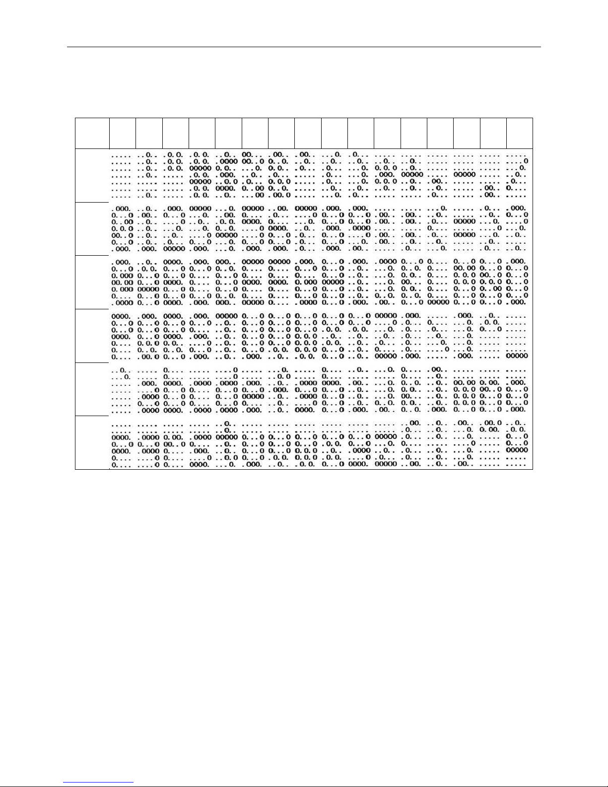
9. CHARACTER SET
9.1 USA,standard character set (20h – 7Eh)
Table 9-1
00 01 02 03 04 05 06 07 08 09 0A 0B 0C 0D 0E 0F
20H
30H
40H
50H
60H
70H
Page 32
WD-2030 XXXX customer display
31
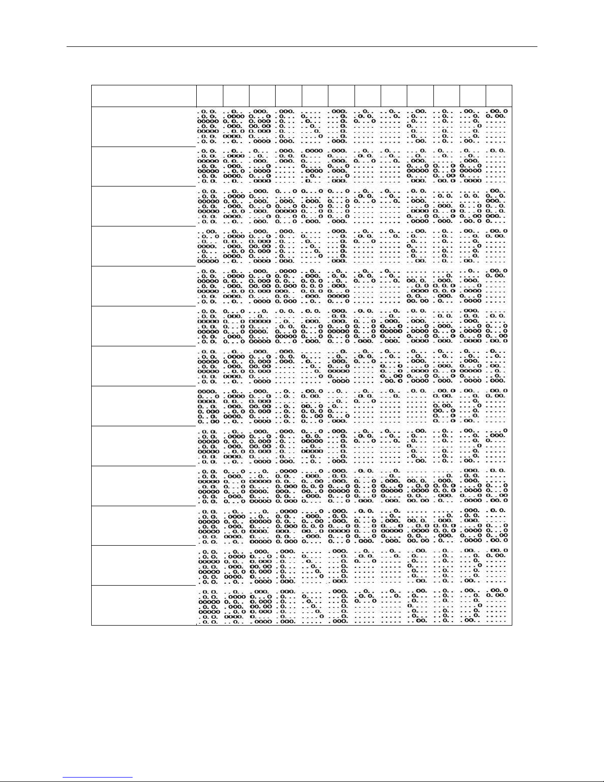
9.2 International Character Sets
Table 9-2
Country\Hex 23 24 40 5B 5C 5D 5E 60 7B 7C 7D 7E
U.S.A
France
Germany
U.K
Denmark I
Sweden
Italy
Spain
Japan
Norway
Denmark II
Slavonic
Russia
Page 33
WD-2030 XXXX customer display
32
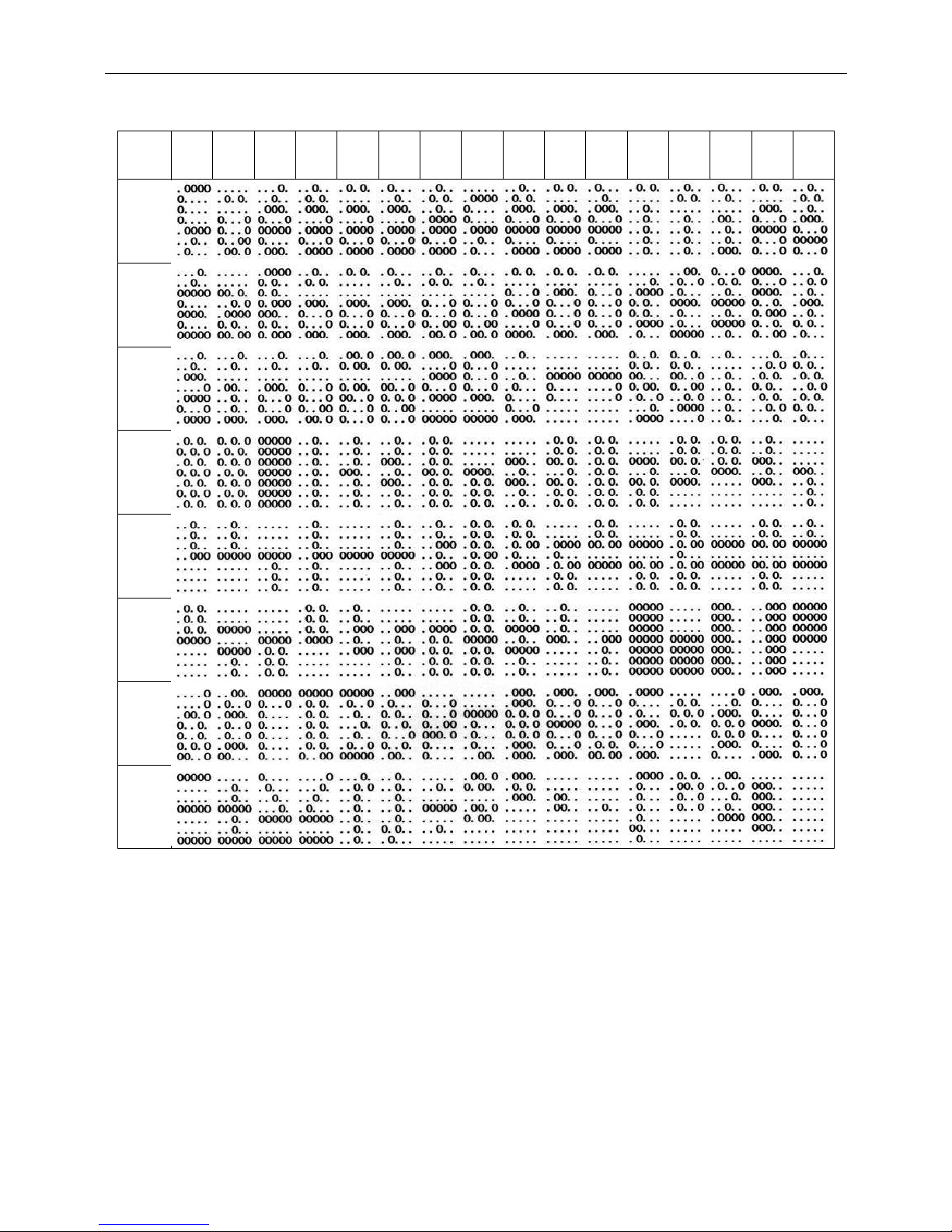
9.3 Page 0 (PC437: USA, Standard Europe) (80H – FFH)
Table 9-3
00 01 02 03 04 05 06 07 08 09 0A 0B 0C 0D 0E 0F
80H
90H
A0H
B0H
C0H
D0H
E0H
F0H
Page 34
WD-2030 XXXX customer display
33
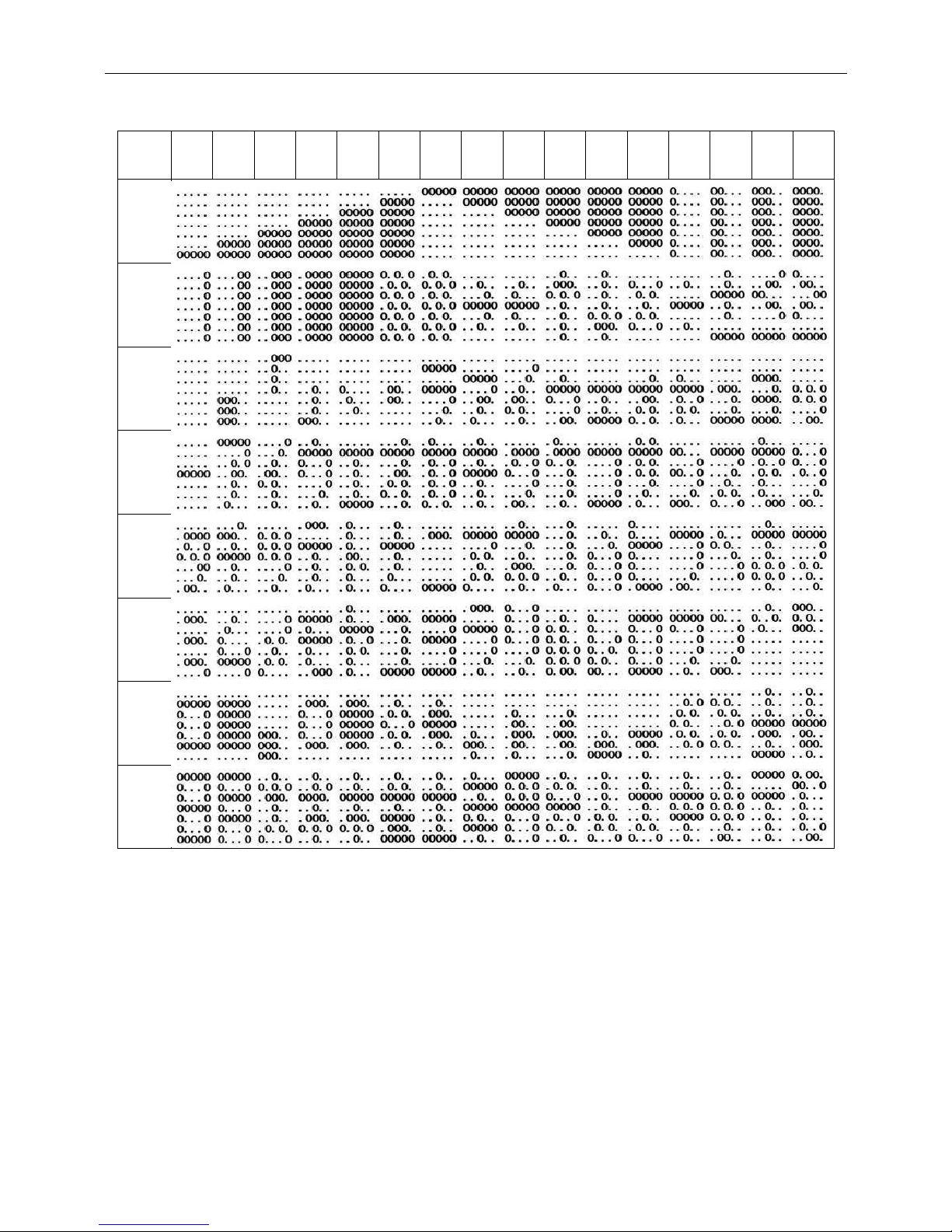
9.4 Page 1 (Katakana) (80H – FFH)
Table 9-4
00 01 02 03 04 05 06 07 08 09 0A 0B 0C 0D 0E 0F
80H
90H
A0H
B0H
C0H
D0H
E0H
F0H
Page 35
WD-2030 XXXX customer display
34
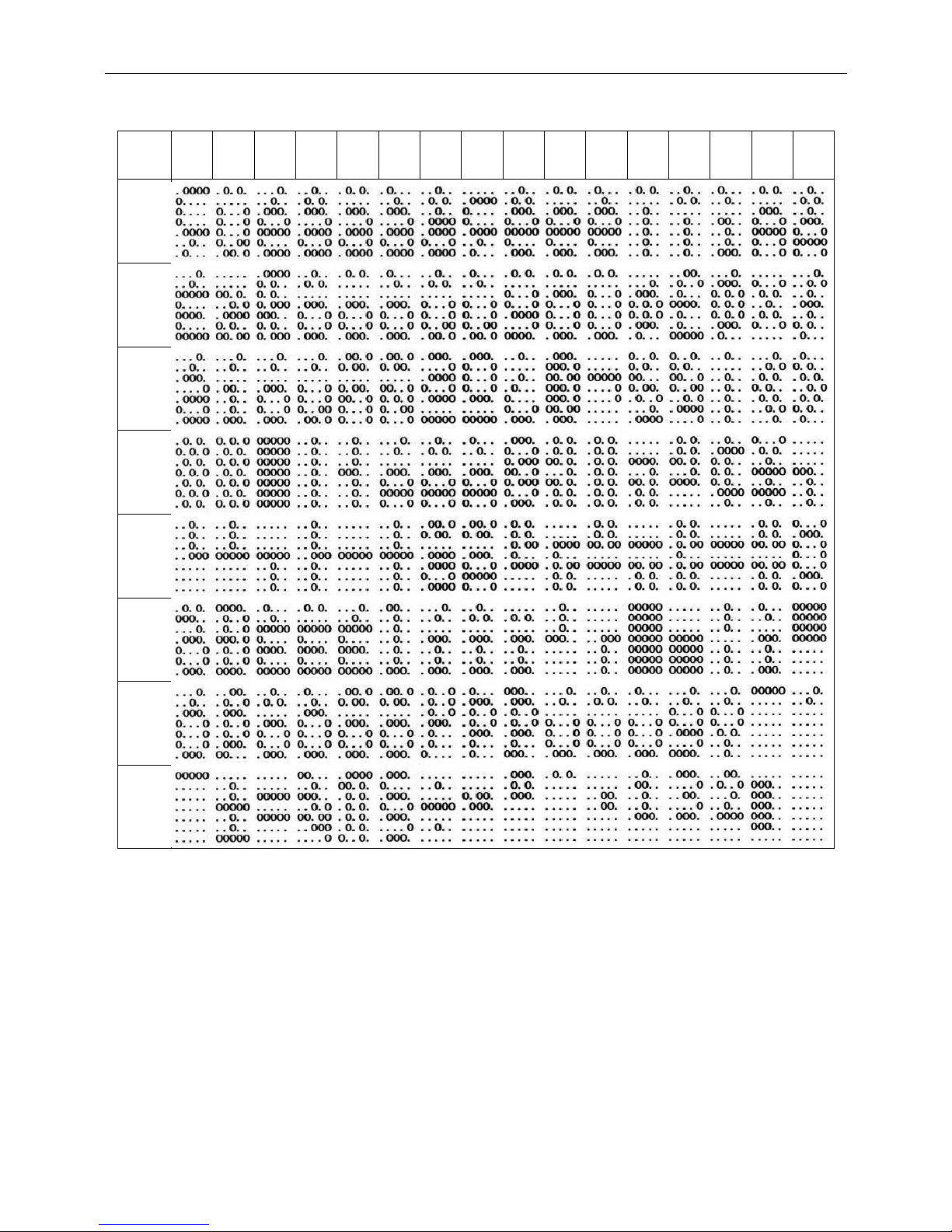
9.5 Page 2 (PC850: Multilingual) (80H – FFH)
Table 9-5
00 01 02 03 04 05 06 07 08 09 0A 0B 0C 0D 0E 0F
80H
90H
A0H
B0H
C0H
D0H
E0H
F0H
Page 36
WD-2030 XXXX customer display
35
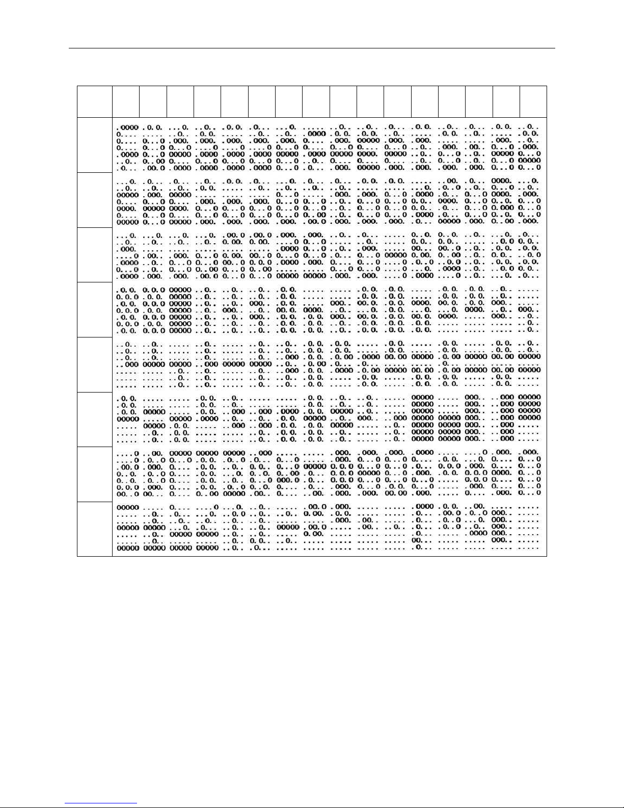
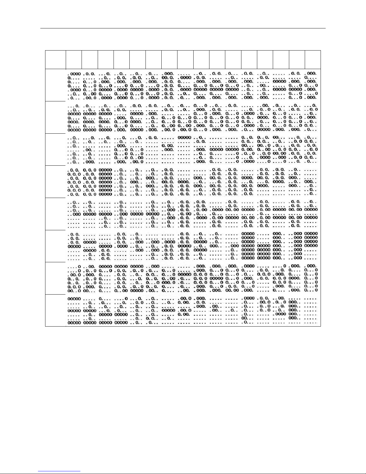
9.6 Page 3 (PC860: Portuguese) (80H – FFH)
Table 9-6
00 01 02 03 04 05 06 07 08 09 0A 0B 0C 0D 0E 0F
80H
90H
A0H
B0H
C0H
D0H
E0H
F0H
Page 37
WD-2030 XXXX customer display
36
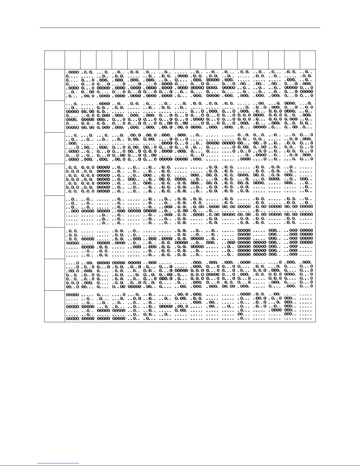
9.7 Page 4 (PC863: Canadian-French) (80H – FFH)
Table 9-7
00 01 02 03 04 05 06 07 08 09 0A 0B 0C 0D 0E 0F
80H
90H
A0H
B0H
C0H
D0H
E0H
F0H
Page 38
WD-2030 XXXX customer display
37
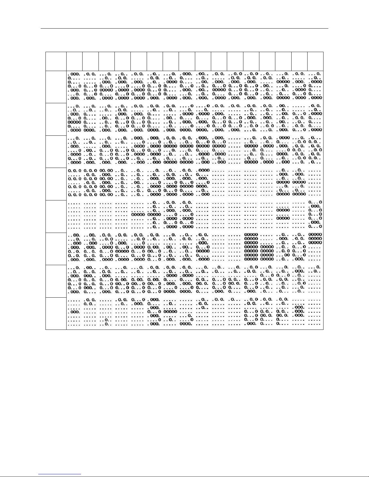
9.8 Page 5 (PC865: Nordic) (80H – FFH)
Table 9-8
00 01 02 03 04 05 06 07 08 09 0A 0B 0C 0D 0E 0F
80H
90H
A0H
B0H
C0H
D0H
E0H
F0H
Page 39
WD-2030 XXXX customer display
38
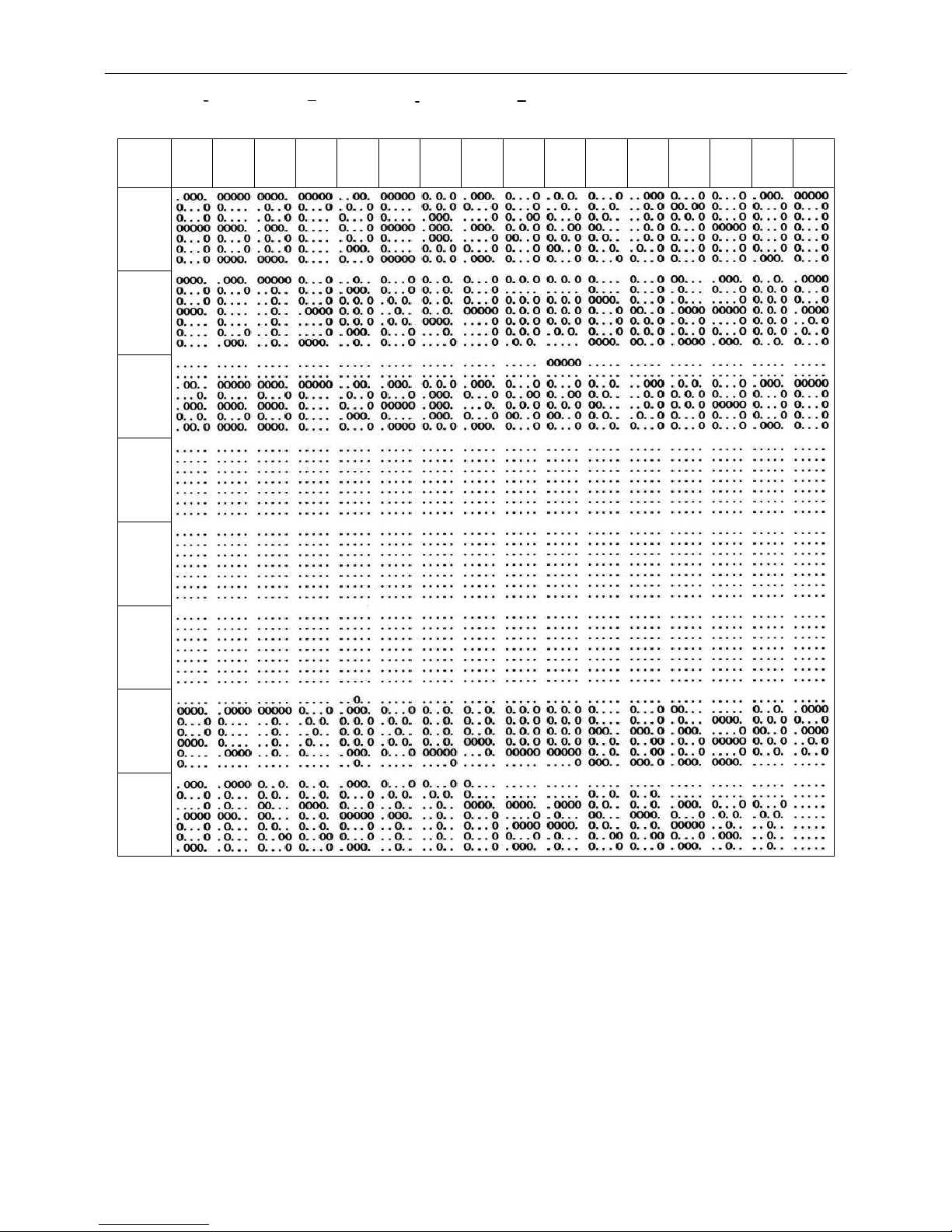
9.9 Page 6 (Slavonic) (80H – FFH)
Table 9-9
00 01 02 03 04 05 06 07 08 09 0A 0B 0C 0D 0E 0F
80H
90H
A0H
B0H
C0H
D0H
E0H
F0H
Page 40
WD-2030 XXXX customer display
39
9.10 Page 7 (Russia) (80H – FFH)
Table 9-10
00 01 02 03 04 05 06 07 08 09 0A 0B 0C 0D 0E 0F
80H
90H
A0H
B0H
C0H
D0H
E0H
F0H
Page 41
WD-2030 XXXX customer display
40
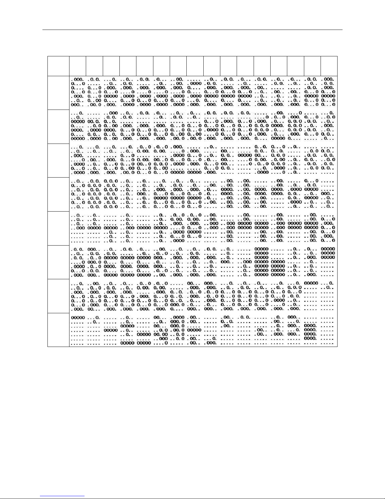
9.11 Page 19 (PC858 Euro) (80H – FFH)
Table 9-11
00 01 02 03 04 05 06 07 08 09 0A 0B 0C 0D 0E 0F
80H
90H
A0H
B0H
C0H
D0H
E0H
F0H
Page 42
WD-2030 XXXX customer display
41
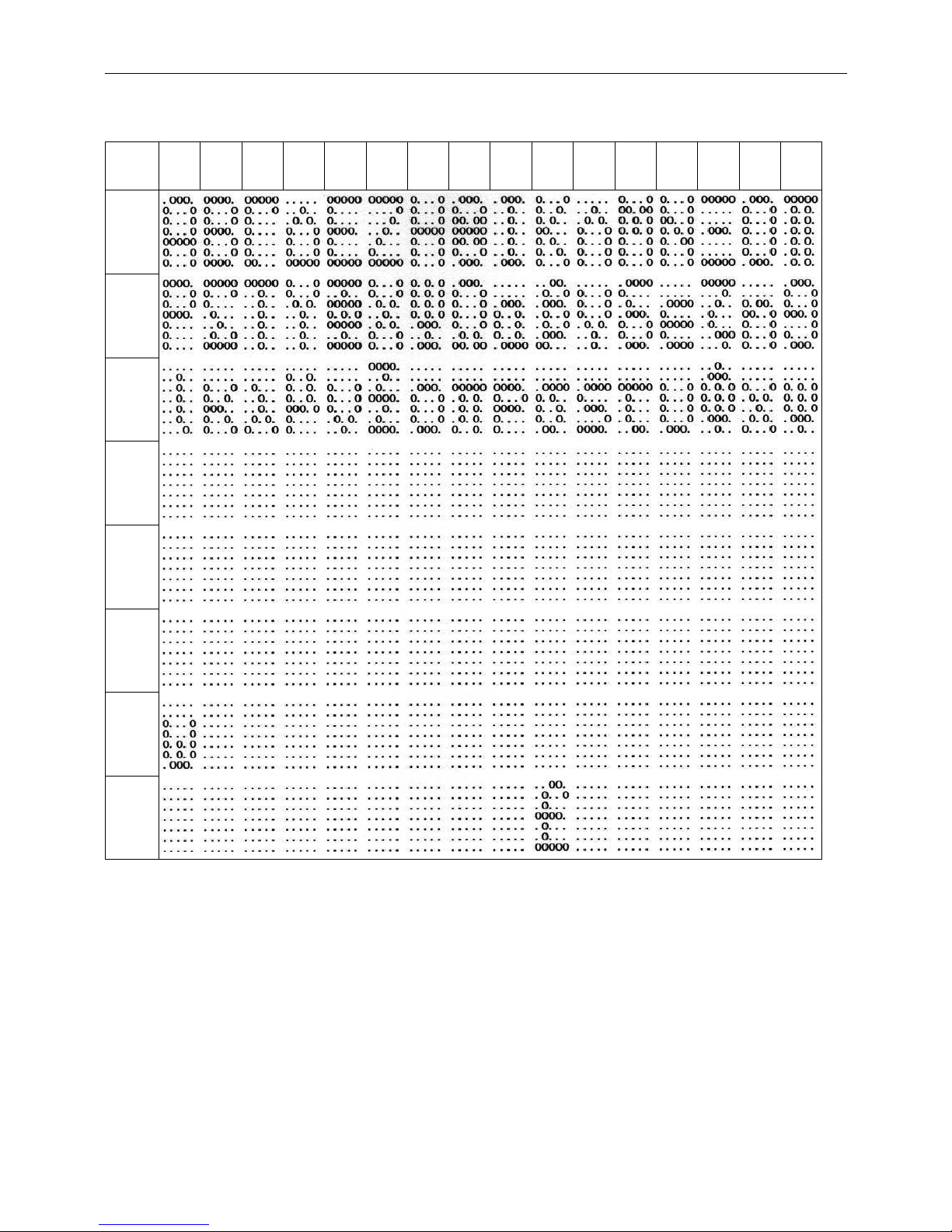
9.12 Page 12 (Greek) (80H – FFH)
Table 9-12
00 01 02 03 04 05 06 07 08 09 0A 0B 0C 0D 0E 0F
80H
90H
A0H
B0H
C0H
D0H
E0H
F0H
Page 43
WD-2030 XXXX customer display
42
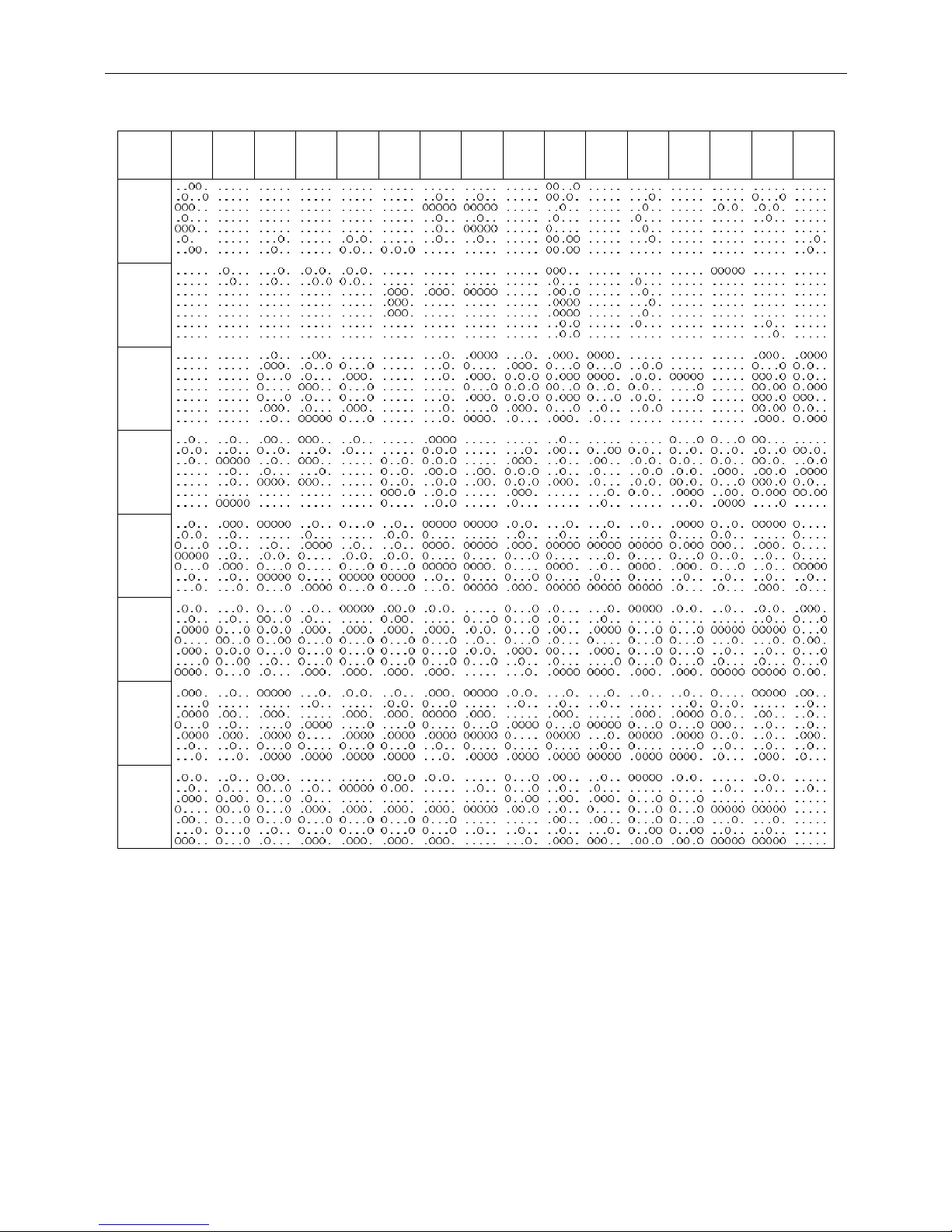
9.13 Page 26 (WPC-1257) (80H – FFH)
Table 9-13
00 01 02 03 04 05 06 07 08 09 0A 0B 0C 0D 0E 0F
80H
90H
A0H
B0H
C0H
D0H
E0H
F0H
Page 44
WD-2030 XXXX customer display
43
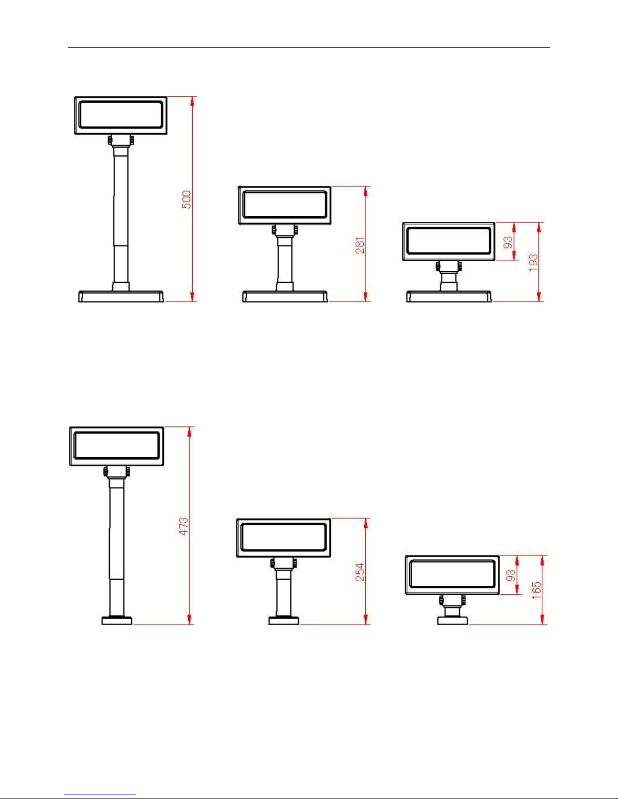
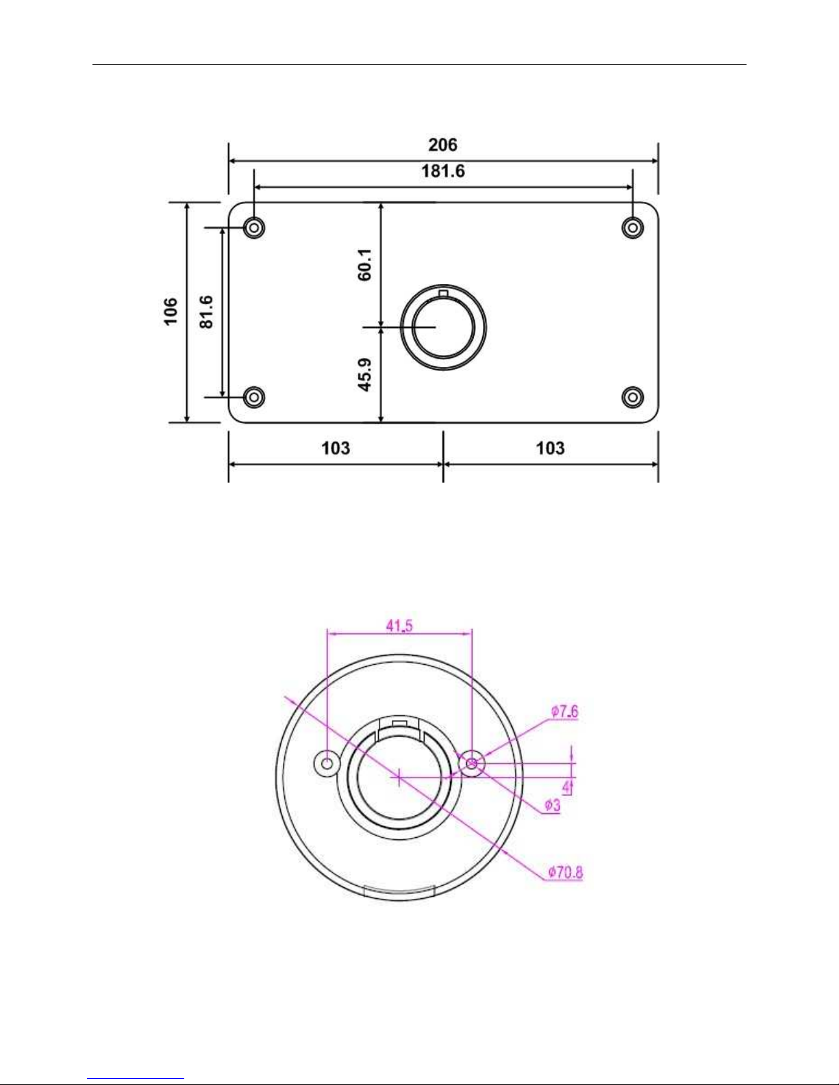
APPENDIX A: Display with Rectangle Base Dimension
APPENDIX B: Display with Round Base Dimension
Unit : mm
Unit : mm
Page 45
WD-2030 XXXX customer display
44
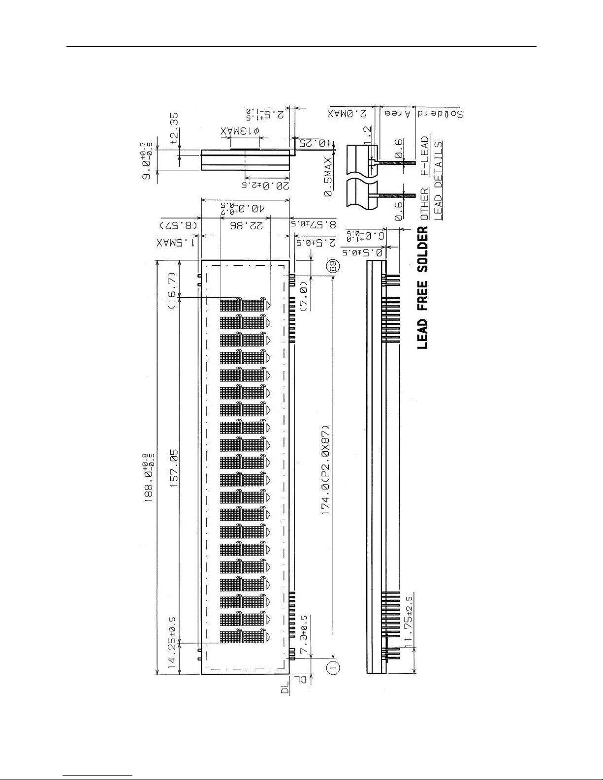
APPENDIX C: Rectangle Base Dimension
APPENDIX D: Round Base Dimension
Unit : mm
Unit : mm
Page 46
WD-2030 XXXX customer display
45
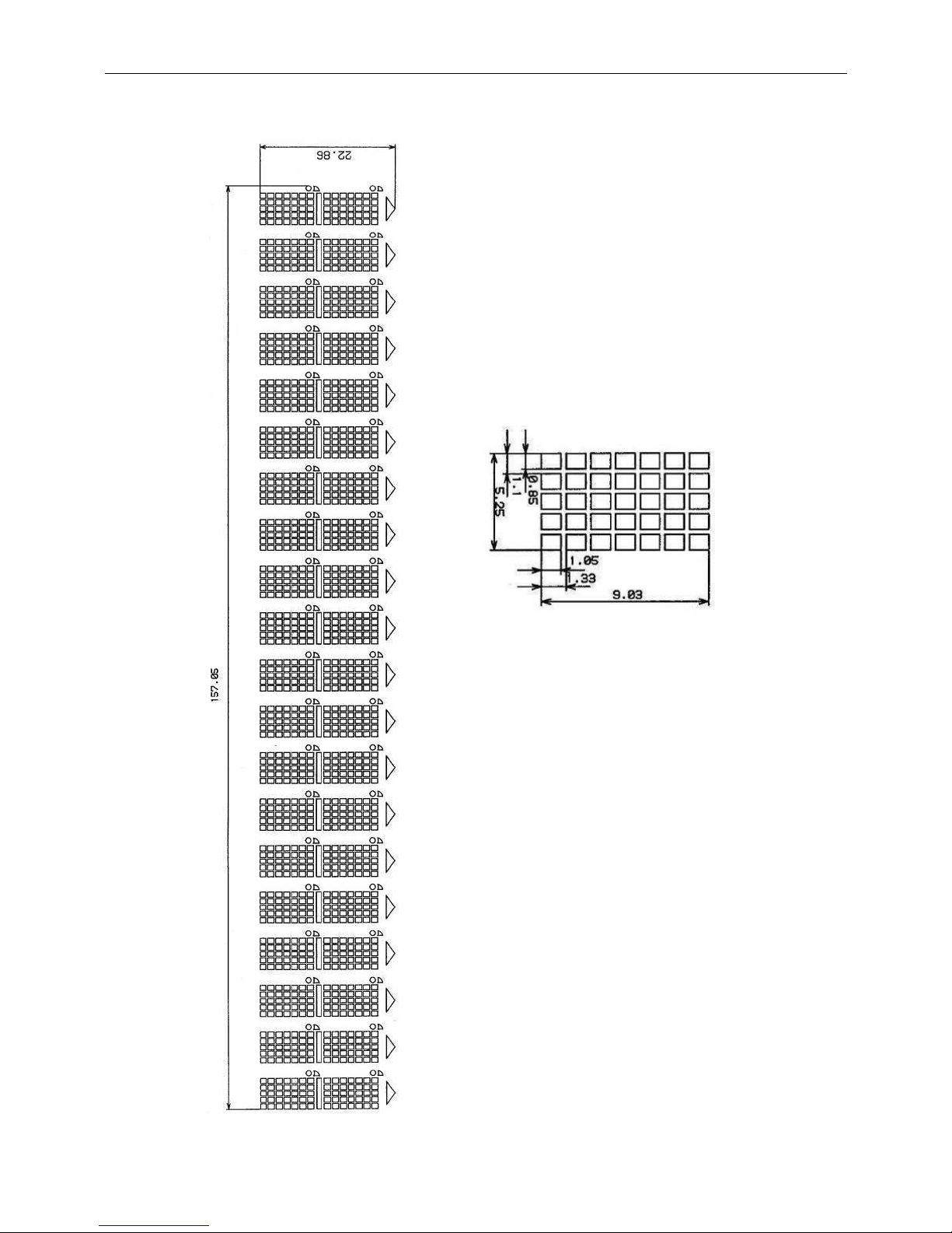
APPENDIX E: Tube Dimension
Unit : mm
Page 47
WD-2030 XXXX customer display
46
Unit : mm
Page 48

WD-2030 XXXX customer display
47
APPENDIX F: Pass Through installation Guide
*
Only for CD5220/UTC/EMAX/EscPOS/DSP-800 emulation
command sets.
*
If printer is EPSON TM serial printer then the pass through cable and
display cable are same.
PC/Host
Display
Printer
 Loading...