

Page 1
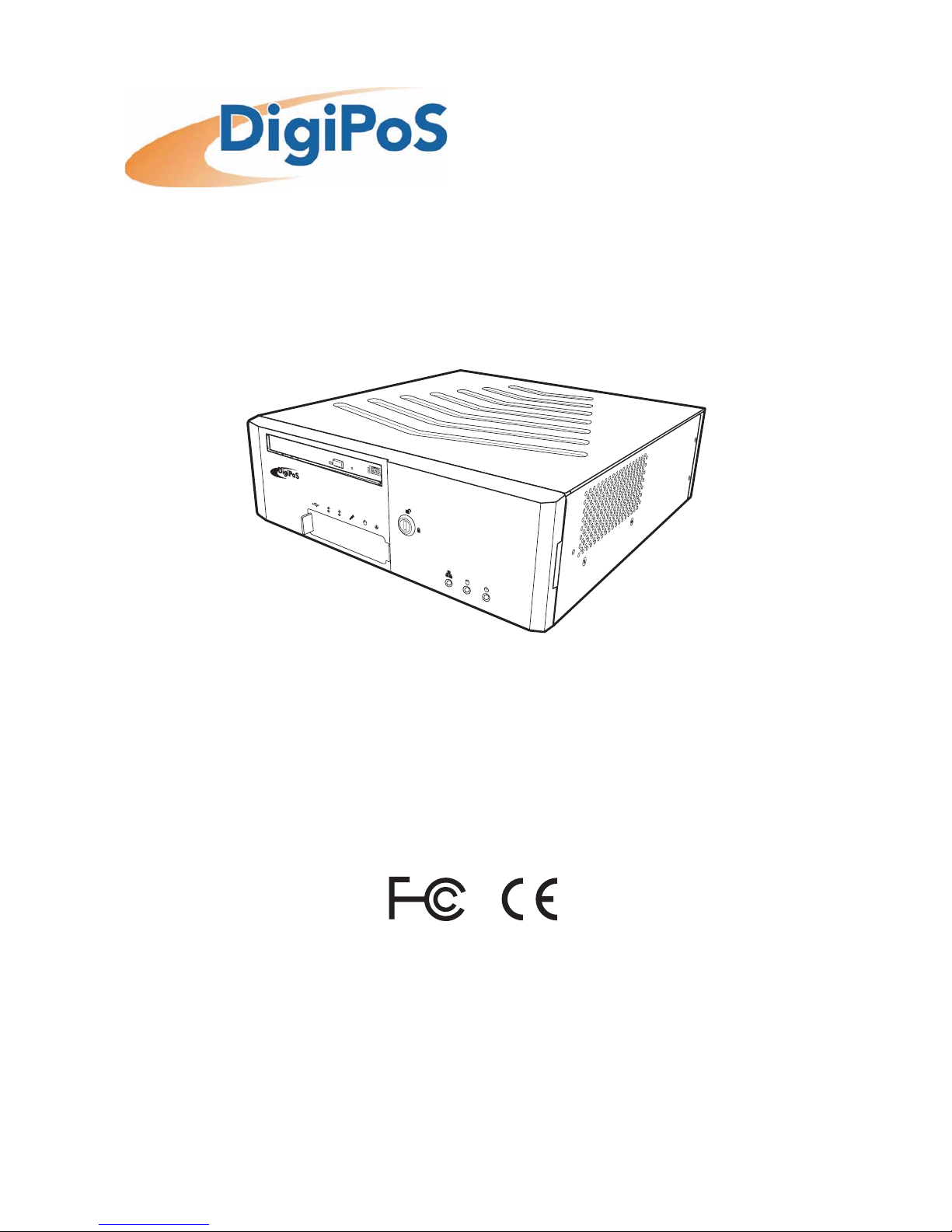
Retail Active 8000
Designed for Retail PoS
Big impact. Small space.
User Guide
RETAIL ACTIVE
Release Version 1.0
August, 2008
Page 2

DigiPoS Retail Active 8000
1
Table of Contents
Preface ...........................................................................................i
FCC Radio Frequency Interference Statement ................................ i
Copyright Statement .............................................................. i
Notice................................................................................ i
Safety Instructions................................................................. ii
Overview ........................................................................................1
Package List ........................................................................ 1
Front Side Components ........................................................... 2
With Cover Fitted............................................................................................ 2
With Cover Removed...................................................................................... 2
Rear Side Components ............................................................ 3
Making Connections ...........................................................................4
Connecting the Power............................................................. 4
Connecting a Monitor ............................................................. 4
Using the VGA port ........................................................................................ 5
Using the DVI-D port...................................................................................... 5
Connecting USB Powered Devices............................................... 5
Using the 12V Powered USB port .................................................................. 6
Using the 24V Powered USB port .................................................................. 6
Connecting USB Devices .......................................................... 7
Connecting a Magnetic Swipe Reader........................................... 8
Connecting Speakers .............................................................. 8
Connecting a Microphone......................................................... 9
Using the DigiPoS Retail Active 8000 .................................................... 10
Powering on the DigiPoS Retail Active ....................................... 10
Power LED......................................................................... 10
HDD Status LED................................................................... 10
LAN Status LED................................................................... 10
Reset Button...................................................................... 10
Flash Card Bay.................................................................... 11
Serial COM Ports ................................................................. 11
Cash Drawer Port ................................................................ 11
Typical POS Device Voltage Requirements................................... 11
Jumper Settings.................................................................. 12
Removing the Front Cover...................................................... 13
Removing the Top Cover........................................................ 13
Installing the Flash Card........................................................ 14
Removing the Hard Disc Drive ................................................. 14
Specifications ................................................................................ 16
Page 3

Preface
i
Preface
FCC Radio Frequency Interference Statement
This equipment has been tested and found to comply with the limits for a class A digital
device. These limits are designed to provide reasonable protection against harmful
interference when the equipment is operated in a commercial environment. This
equipment generates, uses and can radiate radio frequency energy and, if not installed
and used in accordance with the instruction manual, may cause harmful interference to
radio communications. Operation of this equipment in a residential area is likely to cause
harmful interference, in which case the user will be required to correct the interference
at this own expense.
Copyright Statement
© Copyright 2008 DigiPoS Systems. All rights reserved.
No part of this manual, including the products and software described in it, may be
reproduced, transmitted, transcribed, stored in a retrieval system, or translated into any
language in any form or by any means, except documentation kept by the purchaser for
backup purposes, without the express written permission of DigiPoS Systems.
DigiPoS Systems provides this manual “AS IS” without warranty of any kind, either express
or implied, including but not limited to the implied warranties or conditions of
merchantability or fitness for a particular purpose. In no event shall DigiPoS Systems, its
directors, officers, employees or agents be liable for any indirect, special, incidental, or
consequential damages (including damages for loss of profits, loss of business, loss of use
or data, interruption of business and the like), even if DigiPoS Systems has been advised
of the possibility of such damages arising from any defect or error in this manual or
product.
All brand names and registered trademarks mentioned in this manual are the property of
their respective owners and their use here is for reference purposes only.
Notice
The changes or modifications not expressly approved by the party responsible for
compliance could void the user’s authority to operate the equipment.
Specifications and information contained in this manual are provided for informational
use only, and are subject to change or update at any time without notice, and should not
be construed as a commitment by DigiPoS Systems. DigiPoS Systems assumes no
responsibility or liability for any errors or inaccuracies that may appear in this manual,
including the products and software described in it.
Updates to this manual and additional information may be found on the Internet at
http://www.digipos-solutions.com/
For any drivers associated with this DigiPoS, please contact your supplier/distributor or
you can find the latest versions available to download on the Internet at
http://www.digipos-solutions.com/
Page 4

DigiPoS Retail Active 8000
ii
Safety Instructions
• Always read the safety instructions carefully.
• Keep this Manual for future reference.
• Keep this equipment away from humidity and dust.
• Lay the equipment on a reliable flat surface before setting it up.
• The openings on the enclosure are for air convection, hence protecting the equipment
from overheating. DO NOT COVER THESE OPENINGS. For a more detailed explanation
about ventilation requirements, please check the appropriate section within this
document.
• Make sure the voltage of the power source (mains) conforms within the permitted
range before connecting the equipment to the power inlet. If you have any doubts,
please contact a licensed electrician to advise you accordingly.
• Place the power cord in such a way that people cannot step on it. Do not place
anything over the power cord.
• ALWAYS shut down the operating system and disconnect the unit from any power
sources before removing any connections (Keyboard, Mouse, etc..) or opening up the
unit to fit additional cards and or devices.
• ALWAYS shut down the operating system and disconnect the unit from any power
sources before removing any covers or attempting to remove internal components.
• All cautions and warnings on the equipment should be noted and adhered to.
• Never pour any liquid into any openings. This could cause damage or electrical shock.
• If any of the following situations arise, have the equipment checked by qualified
service personnel:
- The power cord or plug is damaged
- Liquid has penetrated into the DigiPoS Retail Active 8000 or the external power
supply
- The equipment has been exposed to moisture
- The DigiPoS Retail Active 8000 is not working properly or you can not get it to work
according to the User Manual
- The DigiPoS Retail Active 8000 has been dropped and damaged
- The DigiPoS Retail Active 8000 has obvious signs of breakage or physical damage
• Do not leave this DigiPoS Retail Active 8000 in a non air-conditioned environment with
a storage temperature above 60ºc (140ºf) as it may damage the equipment.
• For reasons of safety, gloves should be worn when assembling the DigiP oS R etail Active
8000 after any work has been carried out.
Page 5
Overview
1
Overview
Congratulations on your purchase of the DigiPoS Retail Active 8000. You are now the
owner of a state-of-the-art POS system. The DigiPoS Retail Active offers unparalleled
features, speed and performance combined with exceptional reliability. It is unrivalled by
other conventional Intel based PCs within the EPoS industry.
Package List
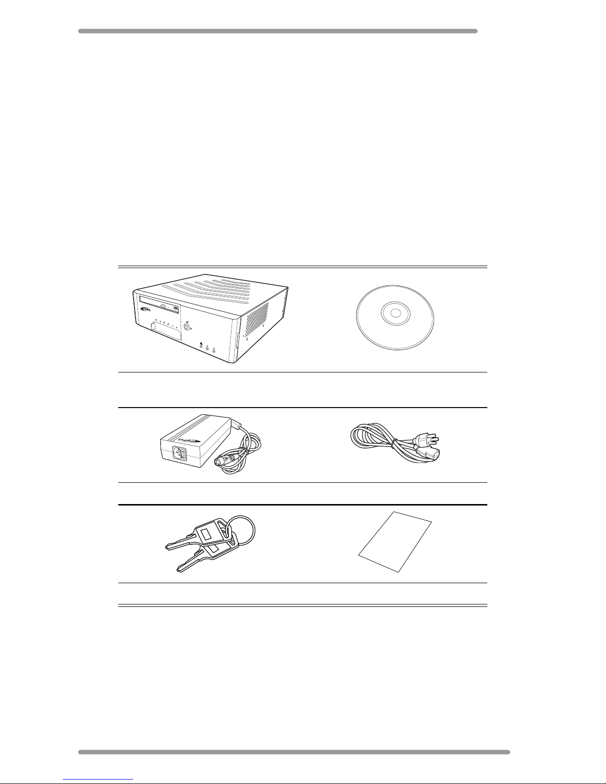
When you receive the DigiPoS Retail Active, ensure all the following items are present in
the package. If any of these items are missing or damaged, please contact your supplier
immediately.
* Note: Power adapter and AC power cord may vary according to the model and region.
DigiPoS Retail Active 8000
CD-ROM
(User Guide included)
Power Adapter * AC Power Cord *
Keys Quick Installation Guide
RETAIL ACTIVE
Quick
Installation Guide
Page 6
DigiPoS Retail Active 8000
2
Front Side Components
With Cover Fitted
With Cover Removed
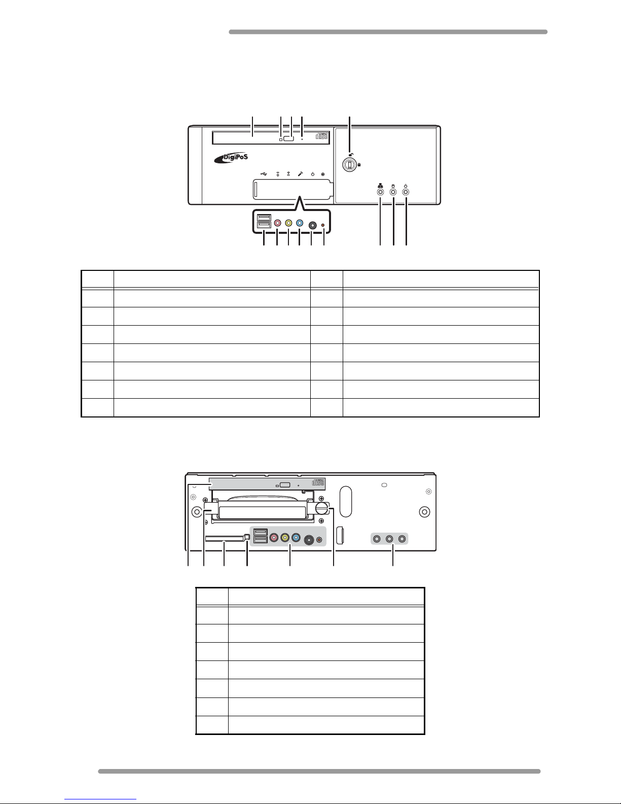
No. Name No. Name
1 CD-ROM drive 8 Line-out port
2 CD-ROM LED 9 Microphone port
3 CD-ROM drawer open button 10 Power button
4 CD-ROM drawer manual open catch 11 Reset button
5 Keylock 12 LAN status LED
6 Two USB ports 13 HDD status LED
7 Line-in port 14 Power L ED
No. Name
1 CD-ROM
2 HDD tray
3 Flash card bay
4 Flash card eject button
5 See previous diagram
6 HDD tray screw
7 See previous diagram
RETAIL ACTIVE
6 7 8 9 10 11 12 13 14
2 3 4 51
3 4 5 71 2 6
Page 7
Overview
3
Rear Side Components
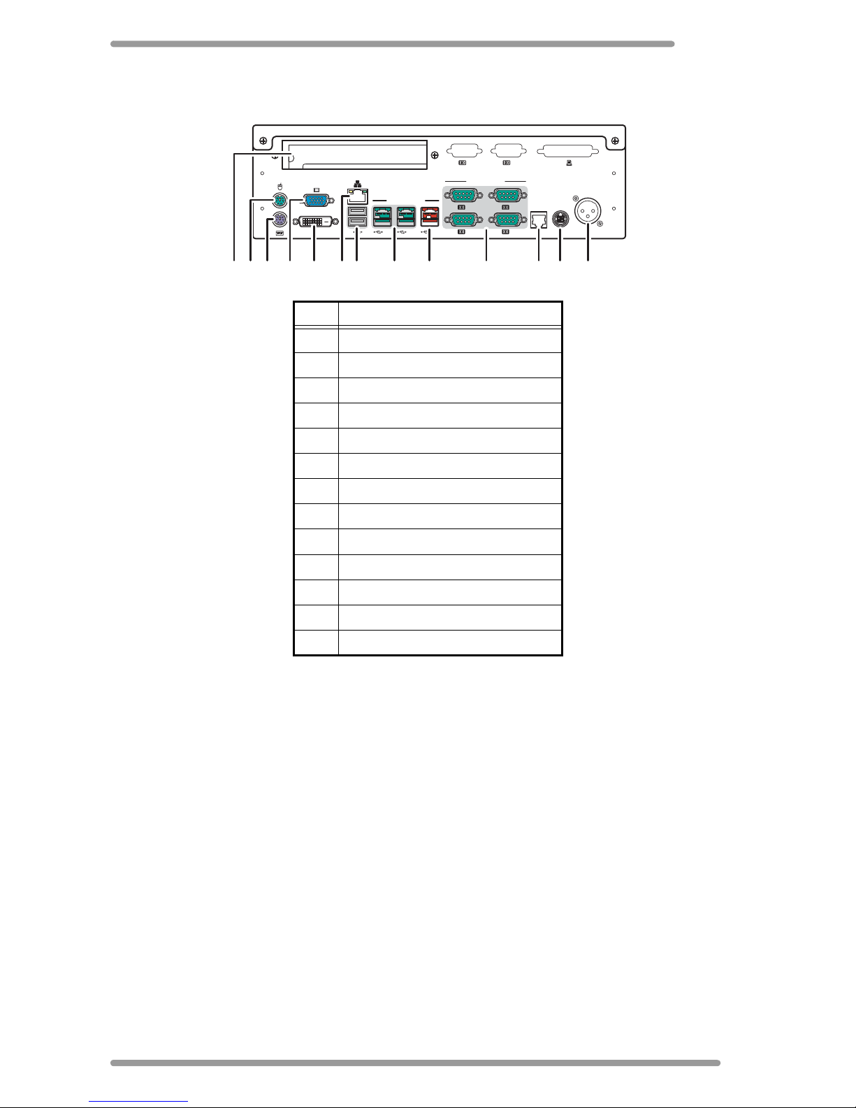
No. Name
1 PCI-1 slot
2 Mouse port
3 Keyboard port
4 VGA port
5 DVI port
6 RJ45 LAN port
7 Two USB ports
8 Two 12V Powered USB ports
9 24V Powered USB port
10 Four COM ports
11 Cash drawer port
12 24V DC output
13 External power input
3 1
4 2
6 5
12V12V 24V
CASH DRAWER
POWERED RS232
PCI
DVI
EXTERNAL
POWERED INPUT
24VDC
OUTPUT
POWERED USB
5 7 8 9 121110 131 2 3 4 6
Page 8
DigiPoS Retail Active 8000
4
Making Connections
By using the ports on the rear side of your DigiPoS Retail Active 8000, you can connect it
to various devices. Refer to the procedures described in this section to make connections
to these ports.
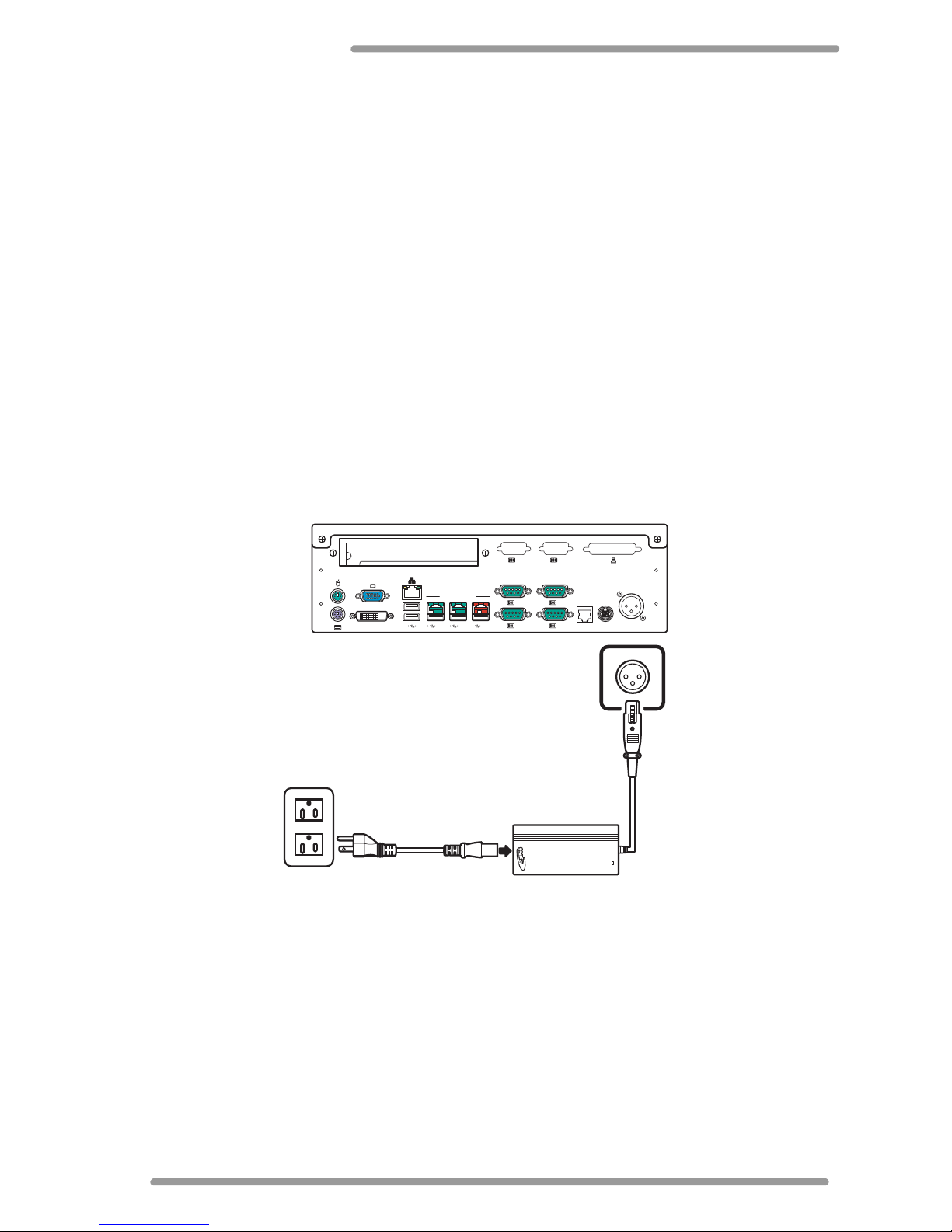
Connecting the Power
Before powering on the DigiPoS Retail Active 8000, you need to follow the steps below to
connect the power cord and the power adapter.
1.Connect the end of the power adapter to the rear side of the DigiPoS Retail Active
8000.
Note: To avoid danger, always ensure that the power cord is NOT connected to
the mains supply before connecting the power adapter to the DigiPoS Retail
Active 8000.
2.Connect the power cord to the power adapter as shown.
3.Connect the end of the power cord to an available wall outlet.
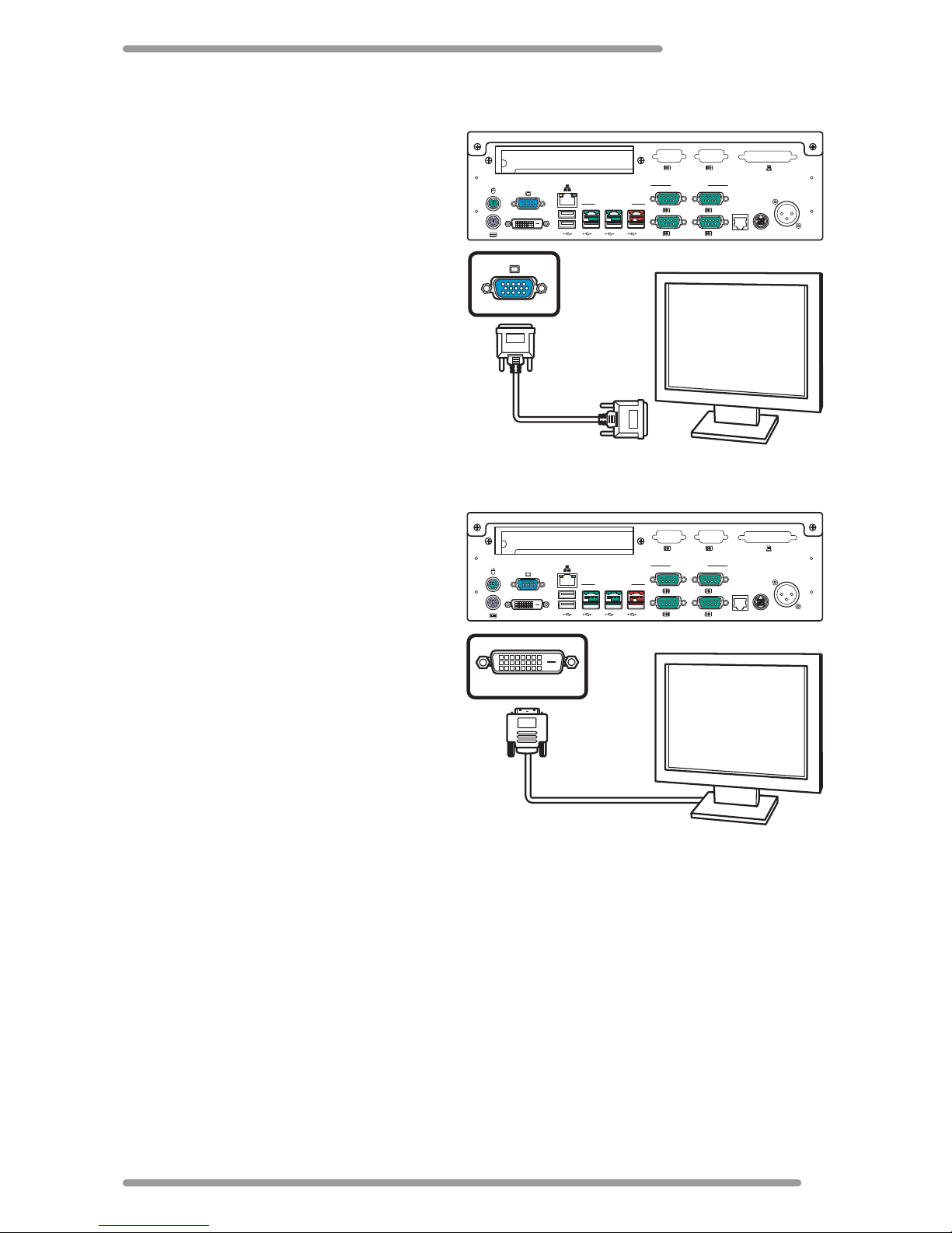
Connecting a Monitor
You can connect the DigiPoS Retail Active 8000 to a monitor using either one of the
following ports:
• VGA port
•DVI-D port
• 12V Powered USB port (see “Using the 12V Powered USB port” on page 6)
Note: You can only connect one monitor to the DigiPos Retail Active 8000 at a time.
3 1
4 2
6 5
12V12V 24V
CASH DRAWER
POWERED RS232
PCI
DVI
EXTERNAL
POWERED INPUT
24VDC
OUTPUT
POWERED USB
Page 9
Making Connections
5
Using the VGA port
You can connect the DigiPoS R etail Active
8000 to a monitor with a VGA (D-SUB 15
pin) cable. Connect one end of a VGA
cable to the VGA port on the rear side of
the DigiPoS Retail Active 8000. Connect
the other end to the VGA port on the
monitor.
Using the DVI-D port
Y ou can connect the DigiP oS Retail Active
8000 to a monitor with a DVI-D cable.
Connect one end of a DVI-D cable to the
DVI-D port on the rear side of the DigiPoS
Retail Active 8000. Connect the other
end to the DVI-D port on the monitor.
Connecting USB Powered Devices
The DigiPoS Retail Active 8000 provides a wide range of output voltages from its Powered
USB ports: 12V and 24V. These ports allow the connected devices to be powered directly
from your DigiPoS Retail Active 8000. You can also use these ports for standard USB data
transmission.
Note: To find out the required voltage of the USB peripheral device to be connected,
please refer to the device’s manual or contact your peripheral device dealer.
3 1
4 2
6 5
12V12V 24V
CASH DRAWER
POWERED RS232
PCI
DVI
EXTERNAL
POWERED INPUT
24VDC
OUTPUT
POWERED USB
3 1
4 2
6 5
12V12V 24V
CASH DRAWER
POWERED RS232
PCI
DVI
EXTERNAL
POWERED INPUT
24VDC
OUTPUT
POWERED USB
DVI
Page 10
DigiPoS Retail Active 8000
6
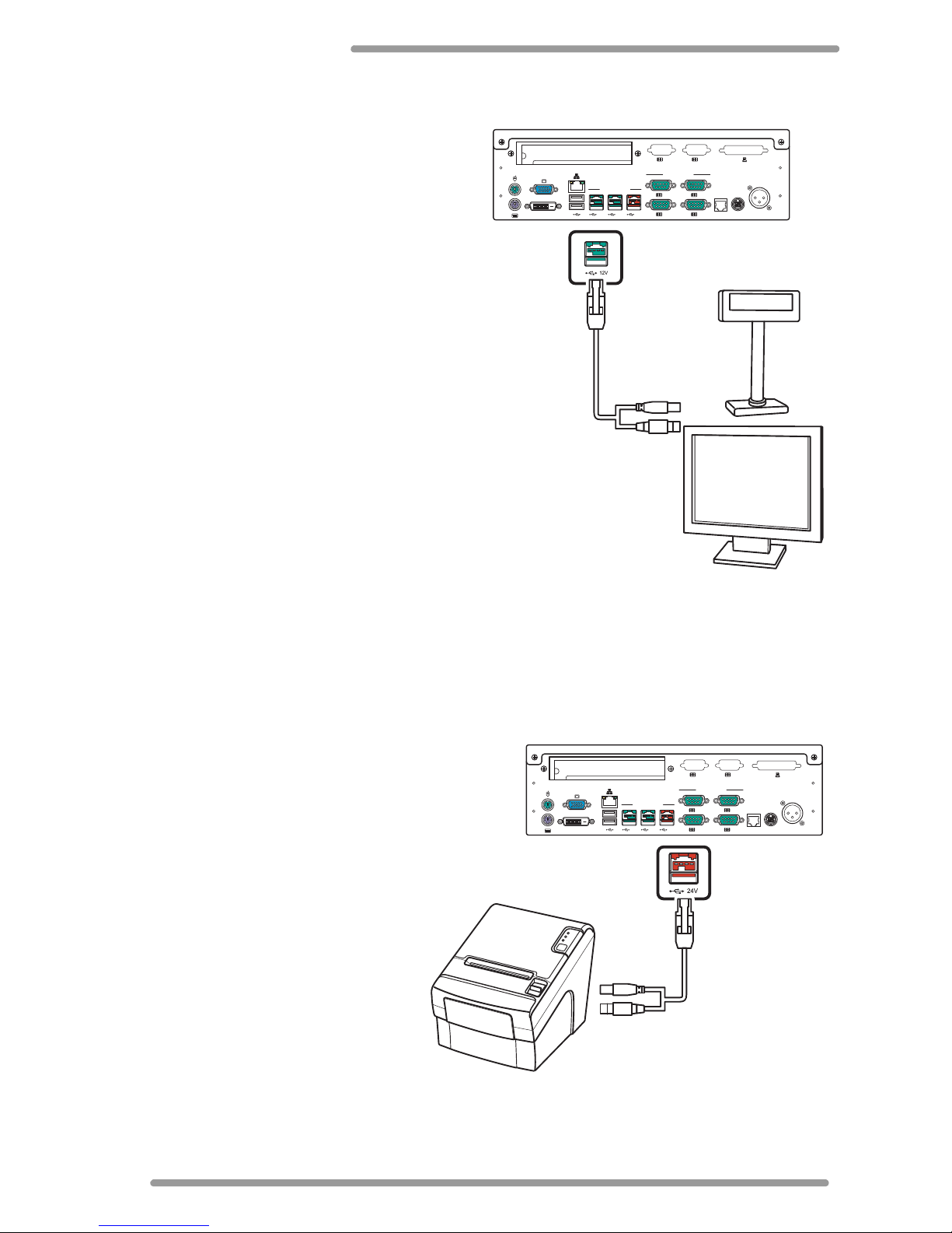
Using the 12V Powered USB port
The 12V Powered USB port (green
connector) is located on the rear side of
your DigiPoS Retail Active 8000. By using
the 12V PoweredUSB port, you can connect
equipment, such as VFDs (Vacuum
Fluorescent Display) and customer displays,
powered by a 12V current.
Connect one end of the 12V USB powered
cable to the 12V PoweredUSB port (green
connector) on the DigiPoS Retail Active
8000. Connect the two connectors at the
other end to a 12V device.
Note: A 12V USB powered cable is required
for this connection. If you need to purchase
one, please contact your vendor.
Using the 24V Powered USB port
The 24V PoweredUSB port (red connector) is located on the rear side of your DigiPoS
Retail Active 8000. By using the 24V PoweredUSB port, you can connect printers powered
by a 24V current.
Connect one end of the supplied 24V
USB powered cable to the 24V
PoweredUSB port (red) on the
DigiPoS Retail Active 8000. Connect
the two connectors at the other end
to a supported printer.
3 1
4 2
6 5
12V12V 24V
CASH DRAWER
POWERED RS232
PCI
DVI
EXTERNAL
POWERED INPUT
24VDC
OUTPUT
POWERED USB
3 1
4 2
6 5
12V12V 24V
CASH DRAWER
POWERED RS232
PCI
DVI
EXTERNAL
POWERED INPUT
24VDC
OUTPUT
POWERED USB
Page 11
Making Connections
7
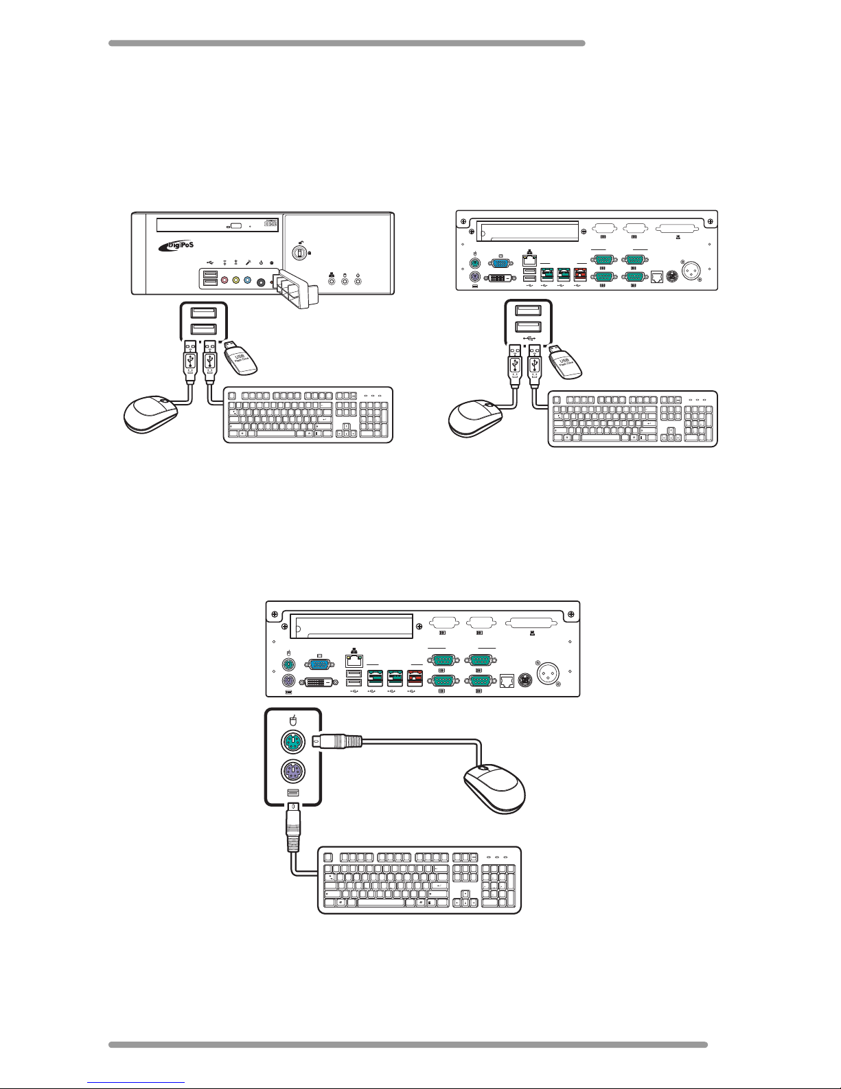
Connecting USB Devices
There are two USB ports on both the front and the rear side of the DigiPoS Retail Active
8000 available for USB peripheral devices. You can connect USB devices, such as a USB
keyboard, a USB mouse, and data storage devices (i.e. USB flash drives).
Connecting a PS/2 Keyboard and Mouse
You can connect a PS/2 keyboard and mouse using the PS/2 keyboard and mouse ports on
the rear side of the DigiPoS Retail Active 8000.
RETAIL ACTIVE
MOLEXMOLEX
Esc F1F2F3F4 F5F6F7F8 F9F10F11F12
Print
Screen
Insert
Backspace
Enter
Enter
AltCtrl
Caps Lock
Tab
Alt Ctrl
Page
Up
Page
Down
+
=
_
-
)(
*
*
& ^%$#@1
~
`
_
/
+
Delete
Scroll
Lock
Num
Lock
Home
Home
798
!
1
End
0
23
4
5
6
7
8
9
Q P
{
[
{
[
\
/
WERTY UIO
A
:
;
"
'
SDFGHJKL
ZXCVBNM
<
,
.
>
?
Ins0Del
.
4
PgUp
3
PgDn
End
65
2
ShiftShift
Pause
Break
Num
Lock
Caps
Lock
Scroll
Lock
3 1
4 2
6 5
12V12V 24V
CASH DRAWER
POWERED RS232
PCI
DVI
EXTERNAL
POWERED INPUT
24VDC
OUTPUT
POWERED USB
MOLEXMOLEX
Esc F1F2F3F4 F5F6F7F8 F9F10F11F12
Print
Screen
Insert
Backspace
Enter
Enter
AltCtrl
Caps Lock
Tab
Alt Ctrl
Page
Up
Page
Down
+
=
_
-
)(
*
*
& ^%$#@1
~
`
_
/
+
Delete
Scroll
Lock
Num
Lock
Home
Home
798
!
1
End
0
23
4
5
6
7
8
9
Q P
{
[
{
[
\
/
WERTY UIO
A
:
;
"
'
SDFGHJKL
ZXCVBNM
<
,
.
>
?
Ins0Del
.
4
PgUp
3
PgDn
End
65
2
ShiftShift
Pause
Break
Num
Lock
Caps
Lock
Scroll
Lock
Front side port Rear side port
3 1
4 2
6 5
12V12V 24V
CASH DRAWER
POWERED RS232
PCI
DVI
EXTERNAL
POWERED INPUT
24VDC
OUTPUT
POWERED USB
Esc F1 F2 F3 F4 F5 F6 F7 F8 F9 F10 F11 F12
Print
Screen
Insert
Backspace
Enter
Enter
AltCtrl
Caps Lock
Tab
Alt Ctrl
Page
Up
Page
Down
+
=
_
-
)(
*
*
& ^%$#@1
~
`
_
/
+
Delete
Scroll
Lock
Num
Lock
Home
Home
798
!
1
End
0
23
4
5
6
7
8
9
Q P
{
[
{
[
\
/
WERT YUI O
A
:
;
"
'
SDFGHJKL
ZXCVBNM
<
,
.
>
?
Ins0Del
.
4
PgUp
3
PgDn
End
65
2
ShiftShift
Pause
Break
Num
Lock
Caps
Lock
Scroll
Lock
Page 12
DigiPoS Retail Active 8000
8
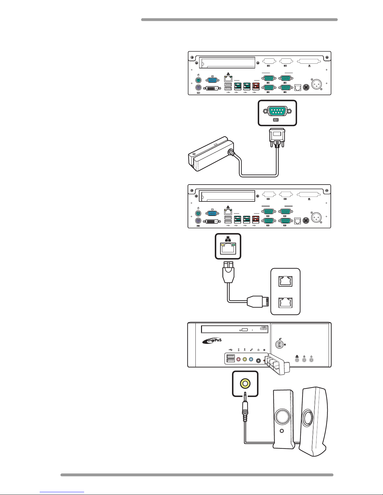
Connecting a Magnetic Swipe Reader
You can connect an MSR (Magnetic Swipe
Reader) using the COM port on the rear
side of the DigiPoS Retail Active 8000.
Connect the MSR to one of the COM ports
as shown.
Connecting to a Network
You can set up an ethernet network
connection via the provided RJ45 LAN
port.
Plug one end of the LAN cable into the
RJ45 LAN port on the rear side of the
DigiPoS Retail Active 8000 and the other
end into an available wall outlet or hub
as shown.
Connecting Speakers
The line-out port on the front side of the
DigiPoS Retail Active 8000 allows you to
connect external speakers or
headphones.
Connect the speakers or headphones to
the line-out port as shown.
3 1
4 2
6 5
12V12V 24V
CASH DRAWER
POWERED RS232
PCI
DVI
EXTERNAL
POWERED INPUT
24VDC
OUTPUT
POWERED USB
1
3 1
4 2
6 5
12V12V 24V
CASH DRAWER
POWERED RS232
PCI
DVI
EXTERNAL
POWERED INPUT
24VDC
OUTPUT
POWERED USB
RETAIL ACTIVE
Page 13
Making Connections
9
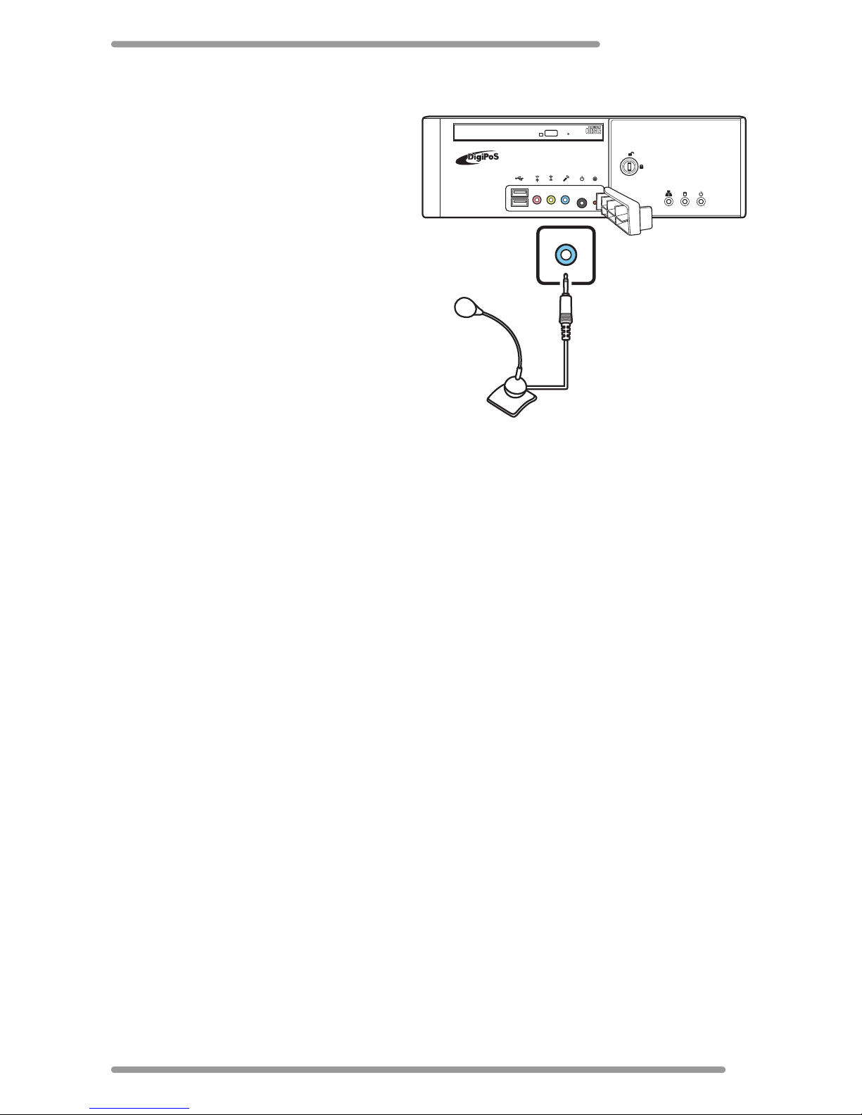
Connecting a Microphone
The microphone port on the front side of
the DigiPoS R etail Active 8000 allows you
to connect an external microphone.
Connect the microphone plug into the
microphone port as shown.
RETAIL ACTIVE
Page 14
DigiPoS Retail Active 8000
10
Using the DigiPoS Retail Active 8000
Powering on the DigiPoS Retail Active
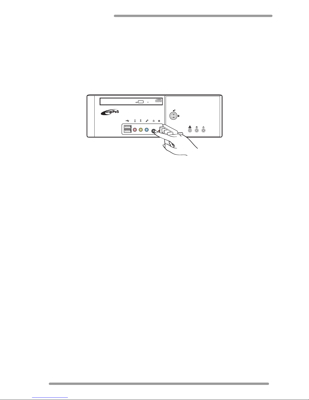
To start using your DigiPoS Retail Active, you must set up the power connections, and
examine to ensure that each piece of equipment is securely connected to its port. Then
press the power button to power on the system as shown. For detailed information on
each connection, see “Making Connections” on page 4.
Power LED
The power LED indicates the power status of the your DigiPoS Retail Active. The LED
lights green when your DigiPoS R etail Active is turned on. It lights orange when on standby
mode. See “Front Side Components” on page 2 for the location of the power LED.
HDD Status LED
Your DigiPoS Retail Active has a green HDD status LED on the front panel (“Front Side
Components” on page 2 for the location), which indicates the current HDD state. The
LED blinks when the HDD is active.
LAN Status LED
Your DigiPoS Retail Active has a LAN status LED on the front panel (“Front Side
Components” on page 2 for the location), which indicates the current network state.
The LED lights green when the link is established. It blinks orange when data transmission
is in progress.
Reset Button
If you encounter any problems or your DigiPoS Retail Active malfunctions, simply press
the reset button to restart the system. See “Front Side Components” on page 2 for the
location of the reset button.
Flash Card Bay
Your DigiPoS R etail Acti ve supports compact flash cards for extra storage. See “Front Side
Components” on page 2 for the location of the flash card bay. See “Installing the Flash
Card” on page 14.
RETAIL ACTIVE
Page 15
Using the DigiPoS Retail Active 8000
11
Serial COM Ports
The DigiPoS Retail Active provides four serial COM ports with adjustable voltage output.
The voltage can be 0V, 5V, 12V, or 24V output. With these serial ports, you can connect
peripheral devices to the DigiPoS Retail Active for both power and data connectivity.
Cash Drawer Port
The DigiPoS R etail Active provides a cash drawer port with adjustable voltage output. The
voltage can either be 12V or 24V output.
Typical POS Device Voltage Requirements
The DigiPoS Retail Active provides two different voltage of PoweredUSB ports located on
the rear side. With these enhanced USB ports, you can connect peripheral devices
directly to the DigiPoS Retail Active via a single USB cable for both power and data
connectivity.
• 24volt PoweredUSB port (Red)
• 12volt PoweredUSB port (Green)
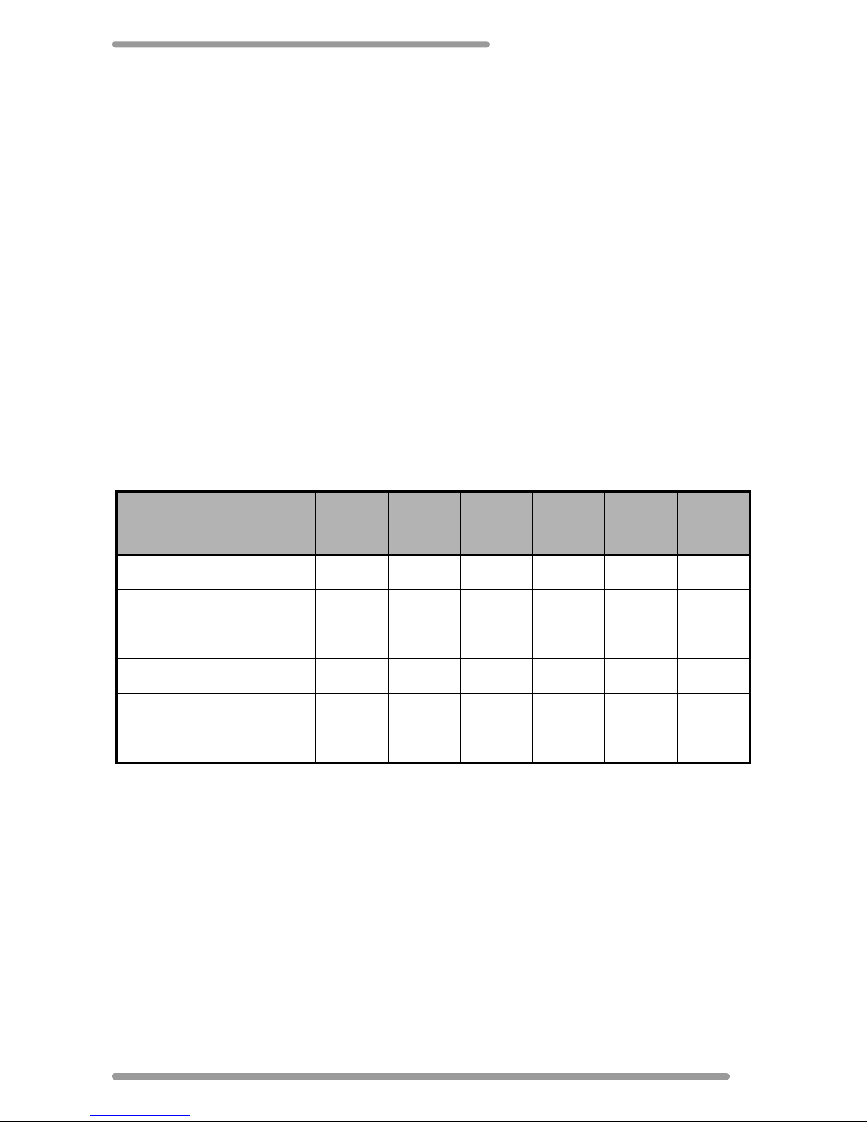
The following table gives some examples of the supported devices by voltage.
Device Examples
0V
(Standard
RS232)
5V 9V 12V 24V 45V
DigiPoS PoS Printer ----Y-
Epson PoS Printer ----Y-
DigiPoS Customer Display -YYYYY
Epson Customer Display ----Y-
MSR Swipe Reader -Y----
DigiPoS LCD Monitor ---Y--
Page 16
DigiPoS Retail Active 8000
12
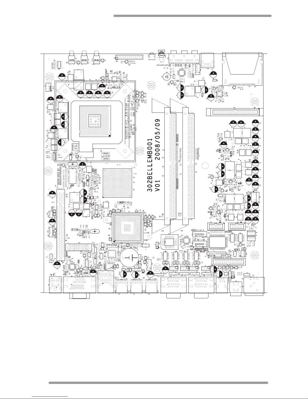
Jumper Settings
Please refer to the illustration below for the jumper settings.
Page 17
Using the DigiPoS Retail Active 8000
13
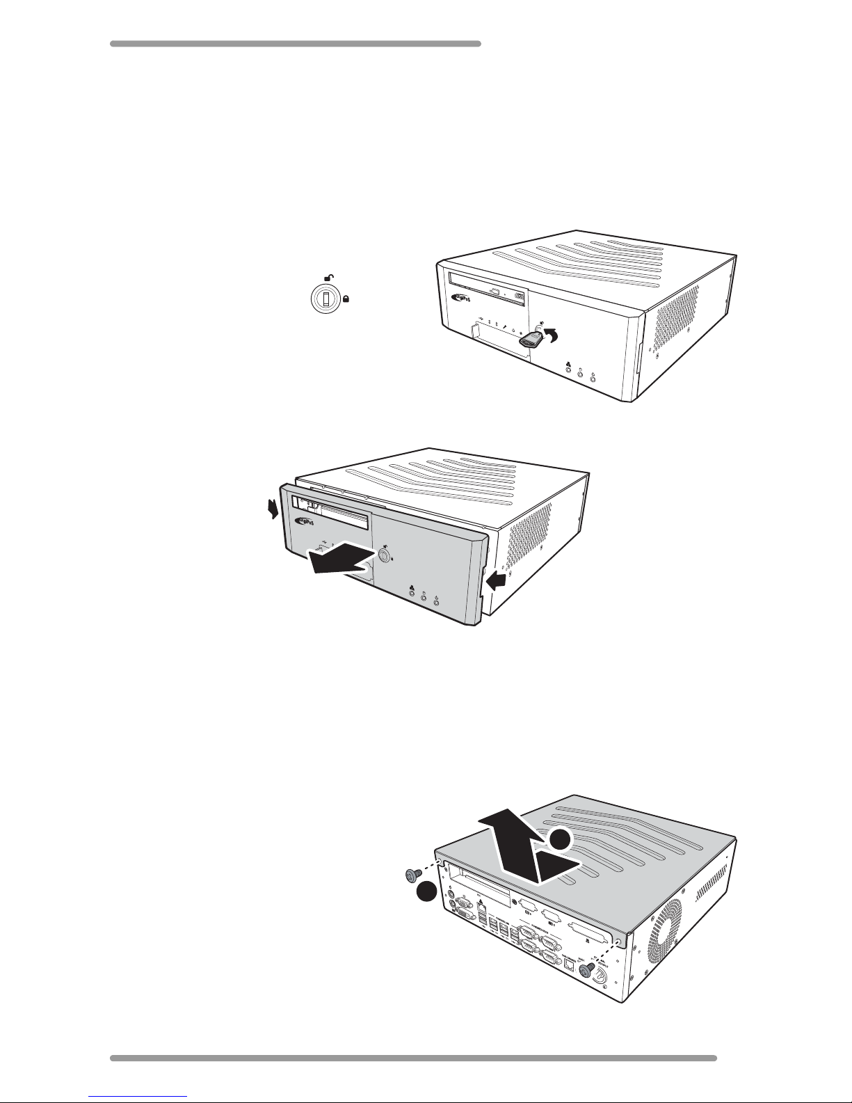
Removing the Front Cover
You are sometimes required to remove the front cover of your DigiPoS Retail Active to
access the flash card bay and for hard disc maintenance. Follow the procedures below to
properly remove the front cover:
1 Close all open applications and turn off the Retail Active.
2 Insert the keys provided with the
package to unlock the keylock.
3 Turn the key to its unlock
position.
4 Grab both sides of the front panel to pull the cover as shown.
Removing the Top Cover
You are sometimes required to remove the top cover of your DigiPoS Retail Active to set
the COM port and cash drawer port voltages. Follow the procedures below to properly
remove the top cover:
* Warning: Be sure to turn the power off the Retail Active before proceeding.
1 Close all open applications and turn
off the Retail Active.
2 Disconnect all power and connecting
cables.
3 Unscrew the two screws on the rear
side of the Retail Active (A).
4 Slide the top cover towards its rear
side to unlock the catch (B).
5 Lift the top cover.
RETAIL ACTIVE
RETAIL ACTIVE
A
B
Page 18
DigiPoS Retail Active 8000
14
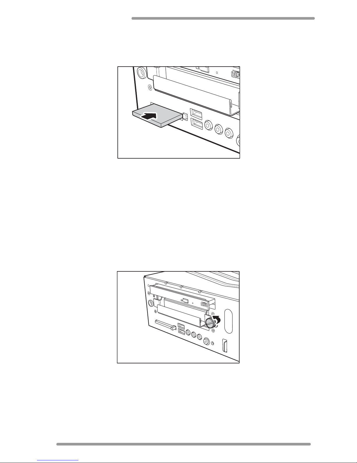
Installing the Flash Card
1 Remove the front cover. See “Removing the Front Cover” on page 13.
2 Insert the flash card to the direction of the arrow.
3 Fully push the flash card until the eject button comes out.
To remove the flash card, simply push the eject button.
Removing the Hard Disc Drive
The DigiPoS Retail Active comes with a removable hard disk drive tray. Follow the steps
below to remove the hard disc drive:
* Warning: Be sure to turn the power off the Retail Active before proceeding.
1 Remove the front cover. See “Removing the Front Cover” on page 13.
2 Unscrew the HDD tray screw.
Page 19
Using the DigiPoS Retail Active 8000
15
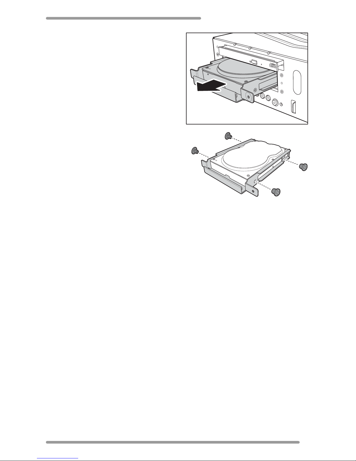
3 Grip the HDD tray and pull it out as
shown.
4 Remove the four screws securing the hard
disc drive from the HDD tray.
5 Slide the hard disc drive out the tray.
Page 20
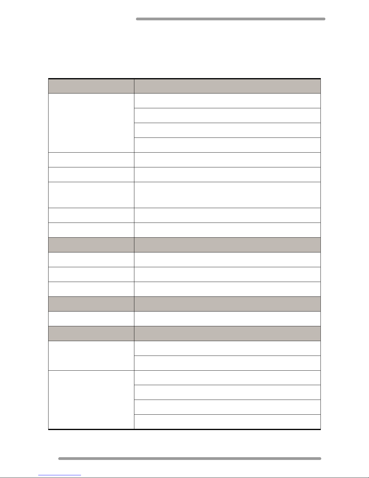
DigiPoS Retail Active 8000
16
Specifications
Mainboard
CPU
LGA 775 Max. TDP=65W
Intel® Celeron® 440 2.0 Ghz 512KB L2 TDP=35W
Intel® Celeron® D processor 352 3.2Ghz 512KB L2
Intel® Core™2 Duo processor E4300, 1.8Ghz 2 MB L2
System Chipset
945GC
FSB
800/533 MHz
System Memory
2 x 240-pin DDR2 667MHz DIMM sockets
Max. up to 2GB memory
Graphic Memory
UMA
Form Factor
Proprietary
Storage
HDD 1 x 3.5” SATA docking (2 x 2.5” SATA optional)
ODD
1 x slim type (optional)
Flash Memory
1 x Compact Flash Type I/II socket
Exansion
PCI
1 (via riser)
Input / Output Ports
Front I/O
2 x USB 2.0
1 x Line-in, 1 x Line-out, 1 x Mic-in
Onboard I/O
1 x USB 2.0
2 x COM
2 x SATA
1 x LED pin header (10-pin)
Page 21
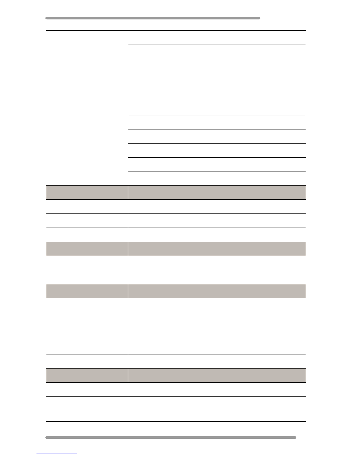
Specifications
17
Rear I/O
2 x 12V powered USB (Max 1.6A)
1 x 24V powered USB (Max 2.3A)
2 x PS/2
2 x USB 2.0
1 x LAN (Giga Lan)
1 x VGA
1 x DVI
4 x Powered COM (Pin 9 select by jumper 0V/5V/12V/24V)
1 x Cash drawer (12V/24V)
1 x DC Input (Neutrik)
1 x 24V DC Output (Hoshiden)
Indicator
Power 1 (Green for on, Orange for stand by)
HDD 1 (Green for on, blinking for active)
LAN 1 (Green for link, blinking orange for transmitting)
Control Key
Power
1 x Button
Reset
1 x Button
Environment
Operating Temperature
0 - 40ºC (32 - 104ºF)
Storage Temperature
0 - 60ºC (32 - 140ºF)
Operating Humidity
20% - 80% Relative Humidity, noncondensing
Storage Humidity
20% - 80% Relative Humidity, noncondensing
Compliant Standards
FCC/CE Class A, LVD, UL, TUV, C-Tick, CCC
Power
Power Adapter
200W, 24V / 8.3A (Fanless)
Power Consumption
CPU core = 90W, 12V = Max. 3.0A, 24V = Max. 2.5A,
Total max. = 60W
Page 22
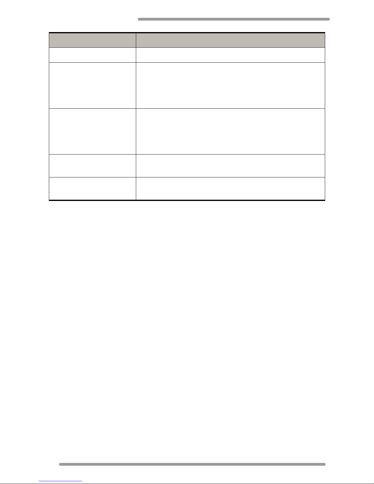
DigiPoS Retail Active 8000
18
Dimension (W x D x H) 293 mm x 307 mm x 90 mm (with front bezel)
Noise Level TDP = 35W, CPU 90% load 24dBA
Operating vibration
Axes: 3 axes / Vertical / Transverse / Longitudinal
Swept Sine, 10-57Hz 0.006in. p-p, 57-500Hz, 0.5g peak, 3
swept per axis
Minimum of 1 minute per Octave, 30 min/axis
Non-operation vibration
Axes: 3 axes / Vertical / Transverse / Longitudinal
Swept Sine, 10-57Hz 0.012in. p-p, 57-500Hz, 1.0g peak, 3
swept per axis
Minimum of 1 minute per Octave, 30 min/axis
Operating Shock
10G: 11ms: 3 shocks per axis: Vertical / Transverse /
Longitudinal
Non-Operating Shock
20G: 11ms: 3 shocks per axis: Vertical / Transverse /
Longitudinal
 Loading...