

Page 1
INTRODUCTION
Annunciator Module V1.1
(DGP2-ANC1B)
Instructions
DGP2ANC1-EI02
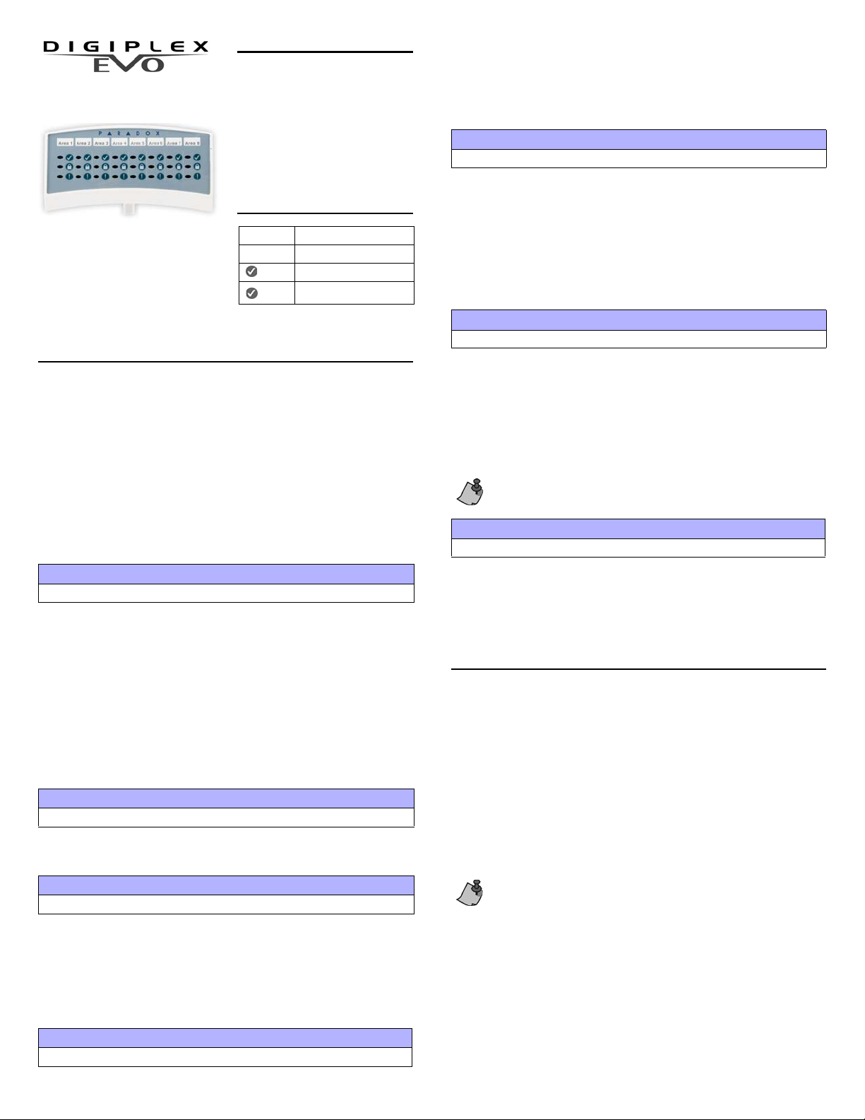
The Annunciator Module (DGP2ANC1B) is a status display device
that is connected to the control
panel’s four-wire combus as a standalone module or mounted on a
keypad. Set the DGP2-ANC1 to
display the status of up to eight
partitions, zones 1 to 48 or zones 49
to 96.
LED FEEDBACK
Slow flash* Zone Alarm
Fast flash Zone Tamper
Flash System not ready
ON System ready
*LED flashes until the partition in alarm
is disarmed
PROGRAMMING METHOD
To program the DGP2-ANC1B, you must enter the Module Programming Mode
using any keypad in the system. To do so:
1. Press and hold the
2. Enter the [INSTALLER CODE].
3. Enter section [4003].
4. Enter the Annunciator’s 8-digit [SERIAL NUMBER] *.
5. Enter the 3-digit section you wish to program.
Program the DGP2-ANC1B using the WinLoad Software or the control panel’s
Module Broadcast feature. Refer t o the Digiplex EVO Programming Guide for
more details.
*Note: The serial number is located on the module’s PC Board.
[0] key.
Section [001] - Option [1] to [8]
Partition Assignment
Use this option to assign access to parti tions. The DGP2-ANC1B will only
display the status of event s tha t occ ur in p a rti tions that ha ve be en assi gned . For
example, if zone 5 in partition 1 has be en breached, but partition 1 is not
assigned to the DGP2-ANC1B, zone 5 will not be displayed. Keys [1] to [8]
represent partitions 1 through 8 respectively*. To assign access to a partition,
enable the option that corresp onds to the desired partition. Partitions 1 to 8 are
enabled by default.
[1] ON = Partition 1 [5] ON = Partition 5
[2] ON = Partition 2 [6] ON = Partition 6
[3] ON = Partition 3 [7] ON = Partition 7
[4] ON = Partition 4 [8] ON = Partition 8
Section [002] - Option [1]
Beeper Mute Mode
Enable option
option to enable the use of options
[1] in section [002] to mute options [2] to [5]. Disable the mute
[2] to [5]. This option is disabled by default.
these troubles occur:
TLM1
Fail to Communicate 1
Fail to Communicate 2
*Note: Option
[1] in section [002] must be disabled.
Fail to Communicate 3
Fail to Communicate 4
Fail to Communicate PC
Section [002] - Option [4]
Beep on Network/Module Trouble
Enable option
these troubles occur:
Module Tamper
Module ROM Check Error
Module Fail to Communicate
Printer Trouble
Module AC Failure
Module Battery Failure
*Note: Option
[4] in section [002] to set the Annunciator to emit a beep* when
Module Supply Output
Missing Keypad
General Failure
Network Overload
Network Com. Error
Missing Module
[1] in section [002] must be disabled.
Section [002] - Option [5]
Zone Trouble
Enable option [5] in section [002] to set the Annunciator to emit a beep* when
these troubles occur:
Zone T amper
Low Battery on Wireless Device
Zone(s) affected by: communication, f ire loop, or CleanMe™ trouble
*Note: Option [1] in section [002] must be disabled.
The trouble beep will stop when the problem is resolved, or if you
press the [TRBL] key from any keypad on the network. This applies to
Section [002], options [2] to [5].
Section [003]
Status Display Mode
Enter a value between 000 and 005 in section [003] to set which status the
Annunciator will display.
000 = Partition Status (default)003 = Future Use
001 = Future Use 004 = Zones 01 to 48
002 = Future Use 005 = Zones 49 to 96
SPECIFICATIONS
Input Voltage: Typically 11-16Vdc
Compatibility: EVO48, EVO192
Current Consumption: Min:15mA Typ:50mA Max:100mA
DGP48, DGP848
DGP-NE96, EVO96
WinLoad V2.10 or higher
BEFORE INSTALLING THE DGP2-ANC1B
Choose a position where you will mount the Annunciator either as a stand-alone
module unit (see “Mounting as a Stand-alone Modu le”), or mounted on a ke yp ad
(see “Mounting to a Keypad”). Once the module is connected and programmed,
you can use one of three display label s to reflect the DGP2-ANC1B’s status
display. Should the system require more than one display, you can “stack” up to
three DGP2-ANC1Bs.
Section [002] - Option [2]
Beep on System Trouble
Enable option [2] in section [002] to set the Annunciator to emit an intermittent
trouble beep* every three second s. Troubles may be:
AC Failure
Battery Trouble
Aux. Current Limit
Bell Current limit
*Note: Option
[1] in section [002] must be disabled.
Bell Absent
ROM Check Error
RAM Check Error
Clock loss
Section [002] - Option [3]
Beep on Communicator Trouble
Enable option [3] in section [002] to set the Annunciator to emit a beep* when
Do not remove the DGP2-ANC1B’s guide clip (Figure 1) unless it is
mounted as a stand-alone module. This clip sets the distance between
the DGP2-ANC1B and the keypad or other Annunciators (if they are
“stacked”). If the clip is removed the DGP2-ANC1’s covers cannot be
placed properly.
Mounting to a Keypad
1. Connect one end of the wires to the Annunciator’s network terminals. Do not
close the back and front covers unt il you have decided how you will set the
module.
2. From the keypad’s back plate, cut out section labelled “E” as show n in
Figure 2 on page 2.
3. Loosen keypad’s network terminal screws without disconnecting the wires.
4. From the Annunciator’s backplate, cut out section labelled “A” as shown in
Figure 1 on page 2.
Page 2

5. Fit the Annunciator’s wires through section “A” and then loop them through
A
B
A
75mm
75mm
B
paradox.com
Printed in Canada 07/2007 DGP2ANC1-EI02
the cut-out section of the keypad’s back plate labelled “E” (Figure 2).
6. Connect the Annunciator’s wires to the keypad’s corresponding +, –, GRN
and YEL network terminals.
7. Tighten terminal screws.
8. Join the keypad’s body plates together.
9. Insert the Annunciator ’s back plat e on top of th e keypad, us ing the guide c lip
to set the position.
10. Adjust any loose wiring between the Annunciator and the keypad.
11. Insert screws into slots labelled “C” (Figure 2) to set the back cover.
12. Insert screws into slots labelled “D” (Figure 2) and tighten all screws.
13. Join the Annunciator’s body plates together.
14. Program the Annunciator usin g any keypad on the network.
15. Affix appropriate label to matc h the display mode (see “Section [003]” on
page 1).
Mounting as a Stand-alone Module
1. Connect one end of the wires to the Annunciator’s network terminals. Do not
close the back and front covers unt il you have decided how you will set the
module.
2. Loop the cable through the space of the Annunciator’s back cover. Place
and hold the Annunciator’s back plate to wall. Remove the guide clip if
desired.
3. Insert screws into slots labelled “C” (Figure 2) to set the b ack cover.
4. Insert screws into slots labelled “D” (Figure 2) and tight en all screws.
5. Join the body plates together.
6. Connect the Annunciator’s wir es to the control panel ‘s corresponding +, –,
GRN, and YEL network terminals.
7. Program the Annunciator using any keypad on the network.
8. Affix appropriate label to match the display mode (see “Section [00 3]” on
page 1).
Module Stacking
1. Install Module 1 (see Figure 3) as you would for either a stand-alone or
mounted installation as described in the previous section.
2. Separate Module 1’s body plates. Leave back plate mounted to wall.
3. Cut out space “B” from Module 1’s back plate.
4. Separate Module 2’s body plates, and connect one end of the wires to its
network terminals.
5. Loosen Module 1’s network terminal screws without disconnecti ng wires.
6. Loop Module 2’s wires through the open gap at the top of Module 1’s back
plate (space B in Figure 1).
7. Connect Module 2’s wires to Module 1’s network terminals (Figure 3).
8. Tighten terminal screws.
9. Join Module 1’s body plates together.
10. Insert Module 2’s back plate on top of Module 1, using the guide clip to set
the position.
11. Adjust any loose wiring between Module 1 and 2.
12. Insert screws into slots labelled “C” (Figure 2) to set the back cover.
13. Insert screws into slots labelled “D” (Figure 2) and tighten all screws.
14. Join Module 2’s body plates together.
15. Program Module 2 using any keypad on the network.
16. Affix appropriate label to matc h the display mode (see “Section [003]” on
page 1).
17. Repeat steps 1 to 15 where Module 1 and 2 will be Module 2 and 3 (see
Figure 3).
Figure 1 : Cut-out Spaces
Remove space “B” from any Annunciator that will have additional
modules stacked on top of it as shown in Figure 3. Uppermost
Annunciators such as Module 3 or stand-alone modules do not require
the removal of space “B”.
Figure 2 : Mounting
Figure 3 : Stacking
Warranty
For complete warranty information on this product plea se ref er to th e L imi te d Warranty St a te ment
found on the website www.paradox.com/terms. Your use of the Pa r ado x p ro du ct si gn i fies yo ur acce ptance of all warranty terms and conditions.
Digiplex, Digiplex EVO, and Winload are trademarks or registered trademarks of Paradox Security
Systems Ltd. and its affi li a tes i n Can ada, the United States and other countries. All right s r ese r ved.
Specifications may change without prior notice. One or more of the following patents may apply:
7046142, 6215399, 611 12 56 , 6104319, 5920259, 5886632, 5721542, 5287111, 5119069, 5077549.
Canadian and international patents may also apply.
© 2002-2007 Paradox Security Systems Ltd.
Use a knife to cut away two squares approx. 75mm from the
Annunciator’s back plate. Cut a squa re i n f ront of the guid e cl ip ( sp ac e A) a nd a t
the top of the rim (space B). Dotted lines indicate cutting lines.
 Loading...