

Page 1
One-zone Hardwire Module V2.0
(DGP2-ZX1)
Instructions
DGP2ZX1-EI02
The One-zone Hardwire Module (DGP2-ZX1) is an interface
between the Digiplex (DGP-48) or DigiplexNE (DGP-NE96) control
panels and any hardwired detection devices. The DGP2-ZX1
connects to the Digiplex/DigiplexNE control panels’ communication
network providing you with one additional hardwired input.
WinLoad Security Management Software (refer to the WinLoad
Software Help File for more information).
Section [001] - Option [1]
Tamper Recognition
The DGP2-ZX1 comes equipped with an on-board tamper switch.
When option [1] is enabled in section [001] and the tamper switch
is triggered, a Module Tamper report will be sent to the control
panel via the communication network.
INPUT SPEED TIMINGS
The input speed defines how quickly the input terminal on the
DGP2-ZX1 responds to an open zone. The control panel will only
respond if the zone remains open for the duration of the Input
Speed. All other zone definitions and options don’t come into effect
until the control panel has responded. This feature prevents any
momentary glitches from causing an alarm or unnecessary
reporting.
Input Speed = Base Time x Time Value.
INSTALLATION
The DGP2-ZX1 modules are connected to the control panel’s
communication network in a star and/or daisy chain configuration.
The communication network consists of four wires that provide
power and two-way communication between the control panel and
all modules connected to it. Connect the four terminals labeled red,
black, green, and yellow of each DGP2-ZX1 to the corresponding
terminals on the control panel as shown in Figure 1 on the back of
this instruction. Please refer to the appropriate control panel’s
Installation & Reference Manual for maximum allowable installation
distance from the control panel.
ZONE CONNECTIONS
Each DGP2-ZX1 has one hardwired input terminal that will allow
you to connect up to two (with ATZ enabled) non-bus detection
devices to the Digiplex/DigiplexNE system. Each device connected
to the DGP2-ZX1’s input terminal must be assigned to a zone in
the control panel and the zone’s parameters must be defined. For
more information, please refer to the appropriate control panel
Installation & Reference Manual. The DGP2-ZX1 will communicate
the status of the zones to the control panel through the
communication network. Connect the devices to the DGP2-ZX1 as
shown in Figure 1 on the back of this sheet.
The DGP2-ZX1 follows the ATZ and EOL definitions set
in the Digiplex/DigiplexNE control panels.
PROGRAMMING METHOD
From any keypad connected to the communication network:
STEP 1: Press and hold the [0] key
STEP 2: Enter the [INSTALLER CODE]
STEP 3: Enter section [953] (DGP-48) / [4003] (DGP-NE96)
STEP 4: Enter the DGP2-ZX1’s 8-digit [SERIAL NUMBER]
STEP 5: Enter the 3-digit [SECTION] you want to program
STEP 6: Enter the required data
Section [002]
Base Time
This section determines the unit of time to be multiplied by the
Time Value.
000 = 15 milliseconds
001 = 1 second
002 = 1 minute
Section [003]
Time Value
Enter a 3-digit decimal value between 001 and 255. This decimal
value will be multiplied by the Base Time to determine the input
speed. For example, if section [002] = 001 and section [003] = 030,
the Input Speed will be 30 seconds.
SPECIFICATIONS
On-board tamper switch: Yes
Voltage: 9-16 VDC
Current consumption: 28mA maximum
Number of inputs: 1
Number of zones: 1 (2 with ATZ enabled) standard zone
Input speed: 15ms - 255 minutes
Power-up indication: Green LED illuminated
Proper operation: Red LED flashes
Locate indication: Green LED flashes
Communication Fault
Indication: Green and red LEDs flash alternately
Locate deactivation: Press tamper switch
Humidity: 95% maximum
Please note that the serial number is located on the DGP2-ZX1’s
PC board. We recommend that you use the DGP2-ZX1’s
programming sheet found in the Digiplex/DigiplexNE Modules’
Programming Guide to keep track of what was programmed and
how. This module can also be programmed using the control
panel’s Module Broadcast Feature (refer to the appropriate control
panel Installation & Reference Manual) as well as through the
Page 2
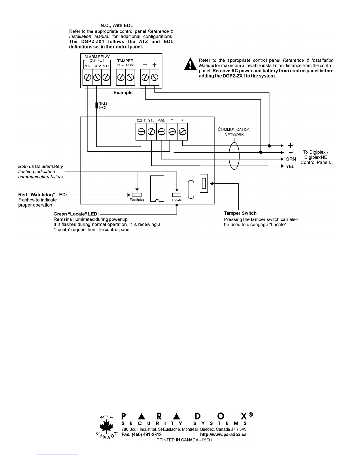
Figure 1: Connecting the DGP2-ZX1
 Loading...