

Digiop G2 Series EDNS4000, Series EDNS5000, Series EDNS6000, Series EDNS7000 Installation, Programming, & User Manual

Digital Video Recorder
Series EDNS4000
Series EDNS5000
Series EDNS6000
Series EDNS7000
4-8-16 camera system
Installation,
Programming,
& User Manual

DigiOpG2 Digital Video Recorder for 4-8-16 cameras Page 2
3040-00057

DigiOpG2 Digital Video Recorder for 4-8-16 cameras Page 3
3040-00057
Warning
Electric Safety
To reduce risk of fire or electrical shock do not expose this product to rain or moisture.
Caution
Lithium Battery
Danger of explosion if battery is incorrectly replaced.
Replace only with the same or equivalent type recommended by the manufacturer.
Dispose of used batteries according to the manufacturer’s instructions.

DigiOpG2 Digital Video Recorder for 4-8-16 cameras Page 4
3040-00057
Table of Contents
1. INTRODUCTION........................................................................................................................................................................... 7
1.1. Specifications of EDNS-4000 Series......................................................................................................................................................................... 7
1.2. Specifications of EDNS5000/EDNS6000 Series......................................................................................................................................................... 8
1.3. Specifications of EDNS7000 Series.......................................................................................................................................................................... 9
2. EDNS4000 SYSTEM STRUCTURE AND INSTALLATION ............................................................................................................ 10
2.1. Getting Started ....................................................................................................................................................................................................10
2.2. System Configuration........................................................................................................................................................................................... 11
2.3. Installation EDNS4000 .......................................................................................................................................................................................... 14
3. EDNS5000/EDNS6000 SYSTEM STRUCTURE AND INSTALLATION .........................................................................................16
4. IDENTIFICATION OF CONTROLS AND CONNECTORS.............................................................................................................. 17
Front Panel EDNS5000/EDNS6000................................................................................................................................................................................ 17
5. CONNECTING THE EDNS5/6000 DIGITAL VIDEO RECORDER.................................................................................................. 21
6. EDNS7000 SYSTEM STRUCTURE AND INSTALLATION ............................................................................................................ 23
7. CABINET AND CONNECTOR LAYOUT.......................................................................................................................................23
8. CONNECTING THE EDNS7000 DIGITAL VIDEO RECORDER. .................................................................................................... 25
9. OPERATIONS OF THE DVR........................................................................................................................................................26
9.1. System Operations................................................................................................................................................................................................26
9.2. Screen Layout.......................................................................................................................................................................................................27
9.3. Detail Functions.................................................................................................................................................................................................... 28
10. SETTING CUSTOMIZED FUNCTIONS......................................................................................................................................... 32
10.1. Camera Setting............................................................................................................................................................................................ 32
10.2. Network ...................................................................................................................................................................................................... 34
10.3. Sensor......................................................................................................................................................................................................... 37
10.4. Camera Control........................................................................................................................................................................................... 39
10.5. Video Input Signal Adjustment..................................................................................................................................................................... 43
10.6. Select Recording.......................................................................................................................................................................................... 44
10.7. Frame Rate Adjustment................................................................................................................................................................................ 47
10.8. Recording Schedule .....................................................................................................................................................................................48
10.9. Extra Setting................................................................................................................................................................................................ 51
11. VIEWER...................................................................................................................................................................................... 54
11.1. Basic Operations.......................................................................................................................................................................................... 54
11.2. Explanations about the Screen...................................................................................................................................................................... 55
11.3. Detail Functions........................................................................................................................................................................................... 56
11.4. Other Configurations................................................................................................................................................................................... 61
11.5. Smart Search ...............................................................................................................................................................................................63
11.6. APP ............................................................................................................................................................................................................. 67
12. APPENDIX.................................................................................................................................................................................. 71
12.1. Pin Assignment of Alarm Port.......................................................................................................................................................................71
12.2. TCP/IP Port Setting Method using the firewall. .............................................................................................................................................. 72
13. INDEX ........................................................................................................................................................................................73

DigiOpG2 Digital Video Recorder for 4-8-16 cameras Page 5
3040-00057
Cautions
Must follow these details to prevent material damage beforehand.
Signs of Caution and Warning
Warning: This sign indicates that the user could die or wounded seriously if not used or installed
properly.
Caution: This sign indicates that the user could be wounded or could expect property damage if not
used or installed properly.
Important Safeguards
Warning
1. Use the power cord, which is supplied or recommended by the supplier.
It may be cause of fire.
2. Do not dismantle or assemble the product.
It may cause malfunction or fire.
3. Do not touch the product with wet hands.
It may become a reason for malfunction or fire.
4. Matters must be ensured to a professional to install the product.
It may become a reason for malfunction, electric shock or fire.
5. Inquire from the place of purchase if the need for installation in distinct place arises.
Delinquent installation may be the reason for malfunction, electric shock or fire.
6. Ground applies to video products equipped with a 3-wire grounding type plug having a third (grounding) pin.
This plug only fits into a grounding-type power outlet.
If grounding is not done, it may cause break down or electric shock.
7. Ground connection must not touch gas pipe, water pipe or telephone line.
If grounding is not done properly, it may cause electric shock.
8. Prevent metallic foreign substance from going inside the product.
It may become a reason for malfunction or electric shock.
9. Do not spray insecticide or flammable spray while driving.
It may be cause for fire.
10. Prevent water from entering inside electrical parts.
Clean with a dry tower or it may become a reason for malfunction or electric shock.
Caution
1. Use the power cord, which is supplied or recommended by the supplier.
The internal fan rotates in high speed and it may become a reason for accident.
2. Do not drop; give strong vibration or shock to the product.
It may become a reason for malfunction.
3. The air inhaler of the front panel and air outlet of the back panel must not be blocked while installing.
The internal temperature of the product would be more than what is allowed and it may become a reason for malfunction or
would generate heat.
4. Do not touch the product or the power cord when there is thunder.
It may become a reason for electric shock.
5. Do not install the product near or on top of heating system.
The internal temperature of the product would be more than what is allowed and it may become a reason for malfunction or
would generate heat.
6. Do not install the product on inclined or unstable location and where vibration could be committed.
It may become a reason for malfunction.

DigiOpG2 Digital Video Recorder for 4-8-16 cameras Page 6
3040-00057
Cautions about the Power
Warning
1. Must use the outlet of the grounding to connect the power cord.
It may become a reason for fire.
2. Do not connect on the middle of power cord or use extension cord.
It may generate heat or cause fire.
3. Do not touch the power cord with wet hands.
It may become a reason for electric shock
4. Prevent wetting the power cord by humidity.
It may generate heat or cause fire. The power cord is not waterproof.
5. Hold the body of the plug while pulling off the power plug.
Do not pull the power line as part of the power line would be cut off and it may generate heat or cause fire.
6. Check the power plug regularly.
By humidity and moderation in smoking, it may cause fire.
7. Pull of the power cord from the outlet when the product is not used for a long time.
It may become a reason for short-circuit or electric shock.
Caution
1. Do not turn of the power by pulling the power plug out.
To turn off the power, click the power button from the front panel.
When the system stop abnormally the power button might not work, then click the power button for at least 4 seconds to turn
OFF the power.
2. Do not cut off the power artificially, give shock or vibration while the hard disk is activating.
It may become a reason for hard disk failure or loss of data.
DigiOpG2 Digital Video Recorder for 4-8-16 cameras Page 7
3040-00057
1. INTRODUCTION
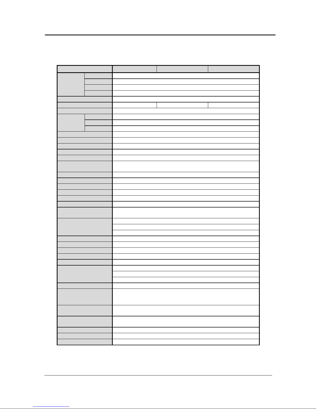
1.1. Specifications of EDNS-4000 Series
4 CH 8 CH 16 CH
CPU
Manufacturer’s Standard
RAM
128MB
VGA
Max 32MB (DVMT)
Hardware
HDD
Manufacturer’s Standard (Max 2ea, Internal CD-RW + HDD 1ea)
OS
Windows XP Embedded
Video Input
4ch 8ch 16ch
Display Speed
Same with Recording Speed
320x240
100 (NTSC 120)fps for ~4ch. / 80~100(NTSC 100-120)fps for 5ch~
640x240
50 (NTSC 60)fps for ~4ch. / 40~50 (NTSC 50-60)fps for 5ch~
Recording Speed
in PAL format.
640x480
30 (NTSC 40)fps for ~4ch. / 20 ~30 (NTSC 30-40)fps for 5ch~
Monitor Output
PC Monitor & Spot Monitor
Recording Resolution
320x240, 640x240, 640x480
Compression Method
Enhanced MPEG (S/W Compression), Limited VBR Control
Byte Size per Image
1~3Kbyte @320x240
Recording Modes
Continuous, Motion Detection, and Sensor Activated
Recording Schedule
Recording Schedule per Camera, per Hour for Weekday/Weekend/Holiday
Frame Rate Adjustment per Hour
Motion Detection
Recording Motion Detection by Setting Motion Detection Area and Motion Detection Alarm
Alarm I/O & Camera Connection
M : N Mapping
Voice Input
1ch (Microphone or line level)
Alarm Input / Output
4 Dry Contact Input / 2(4) Relay Output
PTZ Control
Pan/Tilt/Zoom/Focus/Iris and Preset Control, RS-232C Port (RS-485 Adapter Option)
LAN
10/100BASE-TX Ethernet
Transmission Speed and No. of
Connections
Same as Recording Speed for each Channel
Max 16ch Connection (16 Video Transmission at the same time)
Multi-to-Multi Connection, Multi-Channel Transmission
Live Viewing, Remote Playback and Remote File Copy at the same time (Triplex Transmission)
Remote Transmission
Multi-Site Automatic Event Notification
Remote Control
Remote Pan/Tilt/Zoom/Focus/Iris and Preset Control
Remote Management
Remote Configuration and S/W Upgrade, Remote Time Sync, Periodic Remote Diagnosis
Centralized Backup
Full-Automated Centralized Backup by NetBackup r on the network (Option)
SCSI
None
CD-RW / DVD-RAM
Internal Type, IDE Interface (Option)
Auto-Rebooting and Hard Disk Auto-Recovery
External UPS Interface for Auto-Shutdown
System Recovery after Power
Failure
Automatic Event Notification by LAN
System Operation
External Mouse (Keyboard Unnecessary)
Advanced Functions
Smart Search (8 CH/16 CH), Advanced Post-Processing (8 CH/16 CH)
E-mail Notification, Image Size Setting per Camera
Video Loss Alarm, Recording Failure Alarm, Event Log Viewer
Storage Temperature and
Humidity
-20~60@ / 20~95%RH
Operating Temperature and
Humidity
5~40@ / 20~80%RH
Power
AC100~120V 2A / AC200~240V 1A (Switchable), 50/60Hz
Dimension and Weight
324(W) x 95(H) x 399(D) mm, 9.6kg
Remote S/W (Option)
NetAgent S/W (24ch), RemoteAgent S/W (16ch), WebAgent S/W (4ch, Web Browser-based)
DigiOpG2 Digital Video Recorder for 4-8-16 cameras Page 8
3040-00057
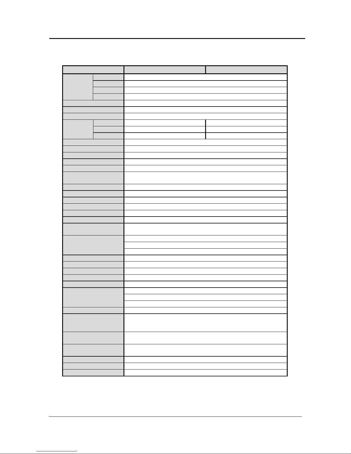
1.2. Specifications of EDNS5000/EDNS6000 Series
EDNS5000 EDNS6000
CPU
Manufacturer’s Standard
RAM
128MB
VGA
Max 32MB (DVMT)
Hardware
HDD
Manufacturer’s Standard (Max 4ea, Internal CD-RW + HDD 3ea)
OS
Windows 2000 Embedded
Video Input
16ch
Display Speed
400 fps
320x240
100 (NTSC 120)fps 200 (NTSC 240)fps
640x240
50 (NTSC 60)fps 100 (NTSC 120)fps
Recording Speed
640x480
25 (NTSC 30)fps 50 (NTSC 60)fps
Monitor Output
PC Monitor & Spot Monitor
Recording Resolution
320x240, 640x240, 640x480
Compression Method
Enhanced MPEG (S/W Compression), Limited VBR Control
Byte Size per Image
1~3Kbyte @320x240
Recording Modes
Continuous, Motion Detection, and Sensor Activated
Recording Schedule
Recording Schedule per Camera, per Hour for Weekday/Weekend/Holiday
Frame Rate Adjustment per Hour
Motion Detection
Recording Motion Detection by Setting Motion Detection Area and Motion Detection Alarm
Alarm I/O & Camera Connection
M : N Mapping
Voice Input
1ch (Microphone or line level), optional 4 ch audio card
Alarm Input / Output
16 Dry Contact Input / 8 Relay Output
PTZ Control
Pan/Tilt/Zoom/Focus/Iris and Preset Control, RS-232C Port (RS-485 Adapter Option)
LAN
10/100BASE-TX Ethernet
Transmission Speed and No. of
Connections
Same as Recording Speed for each Channel
Max 32ch Connection (32 Video Transmission at the same time)
Multi-to-Multi Connection, Multi-Channel Transmission
Live Viewing, Remote Playback and Remote File Copy at the same time (Triplex Transmission)
Remote Transmission
Multi-Site Automatic Event Notification
Remote Control
Remote Pan/Tilt/Zoom/Focus/Iris and Preset Control
Remote Management
Remote Configuration and S/W Upgrade, Remote Time Sync, Periodic Remote Diagnosis
Centralized Backup
Full-Automated Centralized Backup by NetBackup on the network (Option)
SCSI
None (optional)
CD-RW / DVD-RAM
Internal Type, IDE Interface (Option)
Auto-Rebooting and Hard Disk Auto-Recovery
External UPS Interface for Auto-Shutdown
System Recovery after Power
Failure
Automatic Event Notification by LAN
System Operation
External Mouse (Keyboard Unnecessary)
Advanced Functions
Smart Search, Advanced Post-Processing
E-mail Notification, Image Size Setting per Camera
Video Loss Alarm, Recording Failure Alarm, Event Log Viewer
Storage Temperature and
Humidity
Temperature range from -20°C to +60°C/ 20~95%RH
Operating Temperature and
Humidity
Temperature range from 0°C to +40°C/ 20~80%RH
Power
230V AC/50Hz/200W
Dimension and Weight
Industrial 19’’ x 4Hu rack mount type. 483mm (w) x 178mm (H) x 450mm (D), 18Kg
Remote S/W (Option)
NetAgent S/W (24ch), RemoteAgent S/W (16ch), WebAgent S/W (4ch, Web Browser-based)

DigiOpG2 Digital Video Recorder for 4-8-16 cameras Page 9
3040-00057
1.3. Specifications of EDNS7000 Series
Features EDNS7000 series
Basic Models EDNS7000-8 EDNS7000-16
CPU
Manufacturer’s Standard
RAM
256MB
VGA
Max 32MB (DVMT)
HDD
Manufacturer’s Standard (Max 4ea, Internal CD-RW + HDD 3ea)
OS
Windows 2000 Embedded
Compression algorithm Enhanced MPEG II, Hardware compression
Data file format DSF format
Recording period 12~24 GB/day (depend on image complexity)
Hard disk size From 250GB. Contact your Ernitec dealer for more information.
# of camera inputs 8 channels 16 channels
Individual camera resolution 640x480 (interlaced)
Compression modes: Variable bit rate: (VBR)
Constant bit rate (CBR)
Yes
Yes
Recording frame rate at resolution 640 x 480, fps @ 200(PAL)/240(NTSC) 400(PAL)/480(NTSC)
Frame rate for monitoring 400 fps (PAL) / 480 fps (NTSC)
Full motion monitoring by overlay Yes (up to 16 screen mode)
Analogue Monitor output Yes (up to 16 screen mode)
# of sensor inputs 816
# of alarm outputs 8
Sound Recording (line input) 4/8 channel (option) no
Multi-screen playback Yes (up to 16 screen mode)
Event log & search Fully supported
Pan/tilt/zoom & pre-set control Ye s, Pan/Tilt/Zoom/Focus/Iris and Preset Control, RS-232C Port (RS-485 Adapter Option)
Access control by password Yes
Individual file encryption Ye s
Still image to floppy disk Yes (JPEG, BMP format)
Still image printer output Yes
File backup Internal DVD-RAM (EIDE) or CD-RW(EIDE) (optional)
Network for remote surveillance Standard for TCP/IP based network. As option modem
Connection Multi-to-multi, multichannel
# of maximum connections 100
Remote Transmission
Multi-to-Multi Connection, Multi-Channel Transmission
Live Viewing, Remote Playback and Remote File Copy at the same time (Triplex Transmission)
Multi-Site Automatic Event Notification
Remote control Pan/tilt/zoom, preset, aux devices, alarm, screen display, event view
Auto-rebooting after power failure Yes
SCSI
(optional)
CD-RW / DVD-RAM
Internal Type, IDE Interface (Option)
Remote S/W (Option)
NetAgent S/W (24ch), RemoteAgent S/W (16ch)
Approvals EN61000-3-2, EN61000-3-3, EN60950, EN55022, EN50130-4
Operation conditions
Temperature range from 0°C to +40°C/20~80%RH
Storage Temperature and
Humidity
Temperature range from -20°C to +60°C/ 20~95%RH
Dimensions/Weight: 19" x 4Hu, 483 (w) x 178 (H) x 450 (D) mm, 18 Kg.
Power requirements 115 - 230V AC/50Hz/300W
Case Industrial 19’’ x 4Hu rack mount type. 483mm (w) x 178mm (H) x 450mm (D)
DigiOpG2 Digital Video Recorder for 4-8-16 cameras Page 10
3040-00057
2. EDNS4000 SYSTEM STRUCTURE AND INSTALLATION
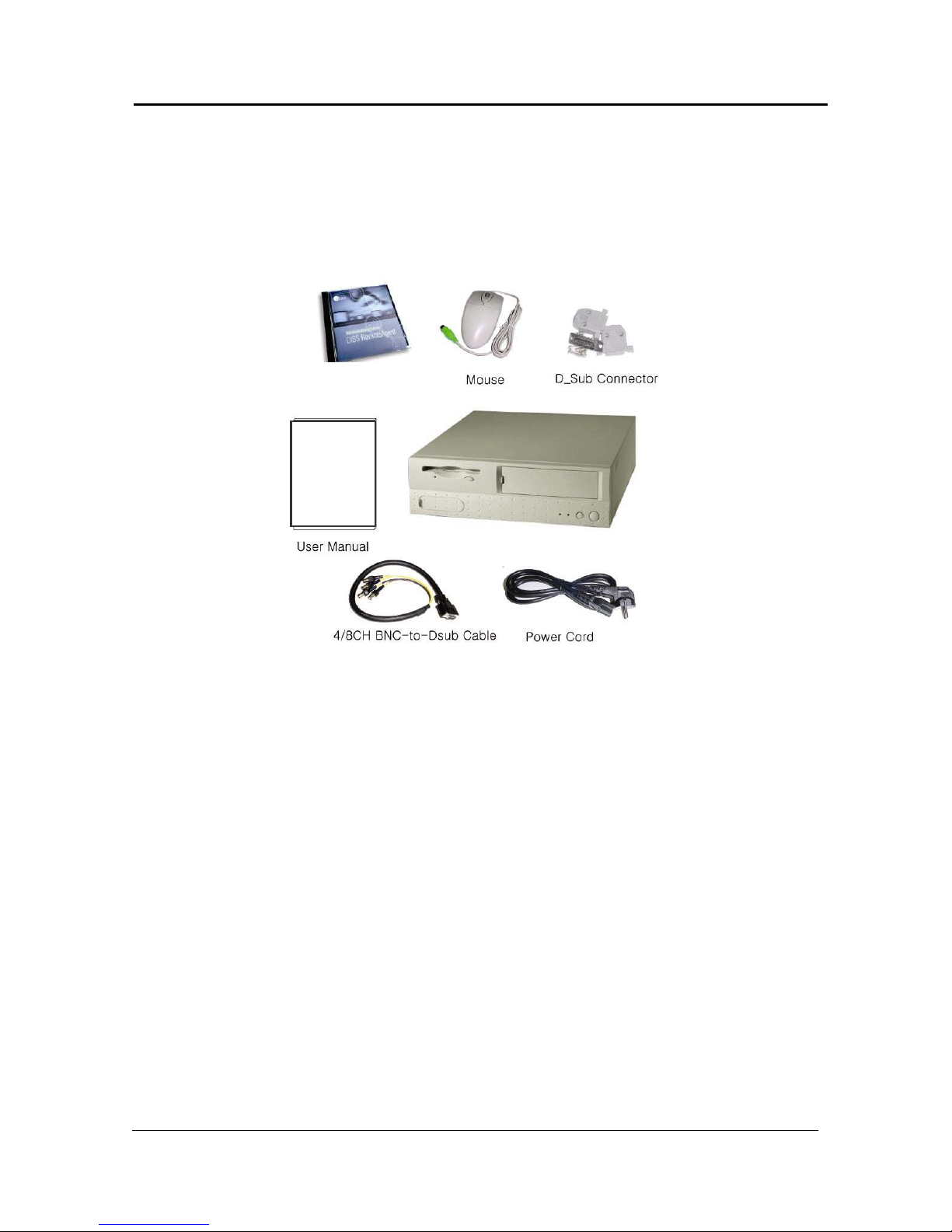
2.1. Getting Started
The following accessories are supplied with the EDNS-4000 series DVR. If any of these items is missing or damaged, notify your dealer
immediately. Keep the packing utilities for moving or storage purposes afterwards.
WebAgent S/W
EDNS 4000 4CH/8CH/16CH DVR
DigiOpG2 Digital Video Recorder for 4-8-16 cameras Page 11
3040-00057
2.2. System Configuration
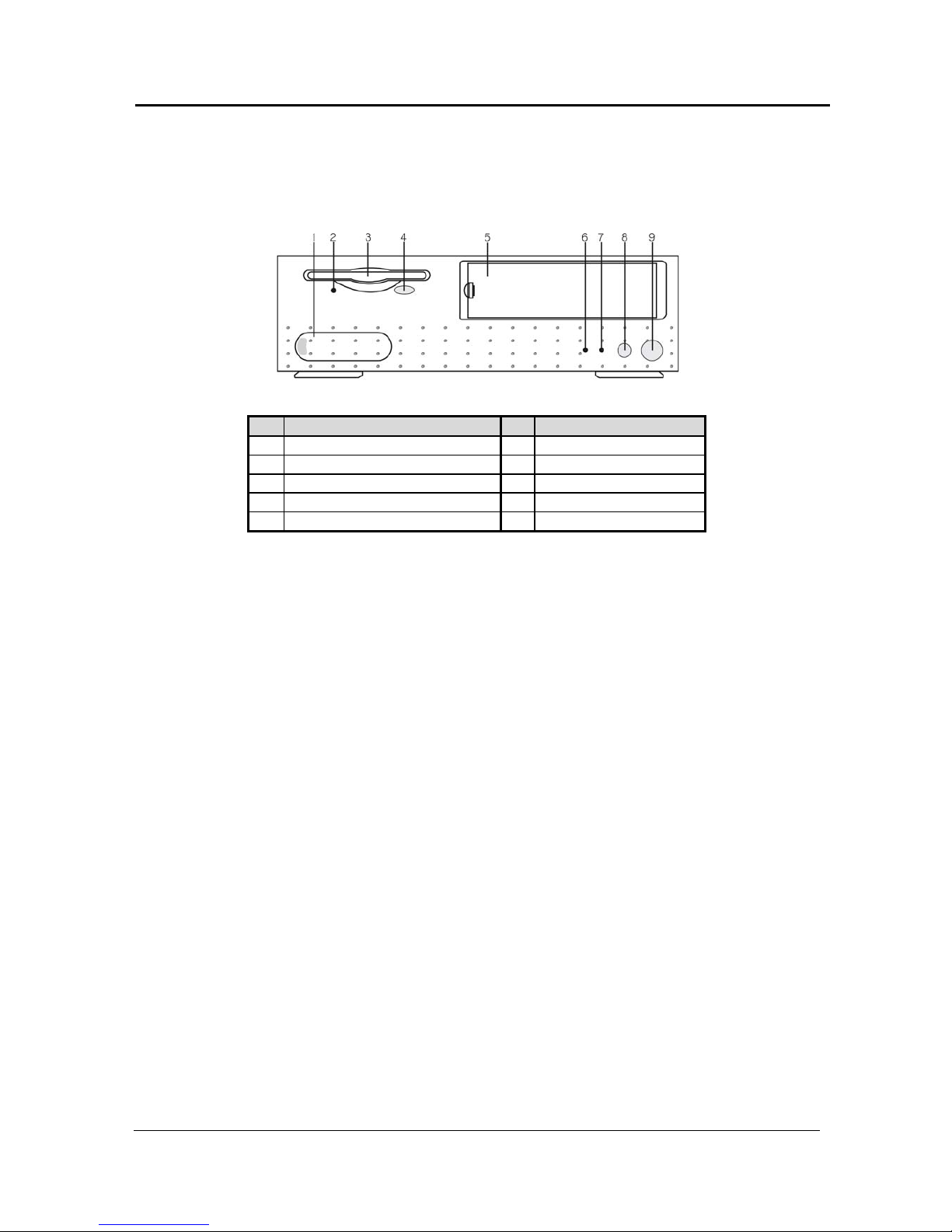
Front Panel EDNS4000
4 CH/8 CH/16 CH
No. Name No. Name
1 Sound/USB Port 6 HDD LED
2 FDD LED 7 Power LED
3 FDD 8 Reset Button
4 FDD Button 9 Power Button
5 CD-RW/DVD-RAM/Removable HDD
Sound/USB Port
Used for connection of speaker, Microphone, or USB to the DVR. Each
built in port is placed when open by pushing aside the handle. Each
port in the back panel is placed with the same composition.
FDD LED
Allows user to know whether the FDD is operating or not.
FDD
Used when saving recorded image to FDD or upgrading the S/W.
FDD Button
Press this button when taking the floppy disk out.
CD-RW/DVD-RAM/Removable
HDD
It is possible to mount CD-RW, DVD-RAM as back-up or removable
HDD as data storage. (Option)
HDD LED
Allow user to know whether reading or writing data to HDD.
Power LED
Allow user to know whether the power is on/off.
Reset Button
EDNS-4000 has a built-in safety feature. When the system is shut down
abnormally, the reset button must be pressed for at least more than 1
second to start normally again to prevent unexpected electric shock.
Then, HDD auto-recovery system operates, restoring back to the
previous state when rebooting.
DigiOpG2 Digital Video Recorder for 4-8-16 cameras Page 12
3040-00057
Power Button
EDNS-4000 is designed to automatically start the operation (AutoRebooting) just after power is supplied. To shut down manually while
operating, the power button must be pressed for at least 1 second. The
monitor displays ‘System Shutdown’ message and shuts down
afterwards. In case of abnormal operation of EDNS-4000, shut down
the power by pressing the button for at least more than 4 seconds.
Then, HDD auto-recovery system operates, restoring back to the
previous state when rebooting
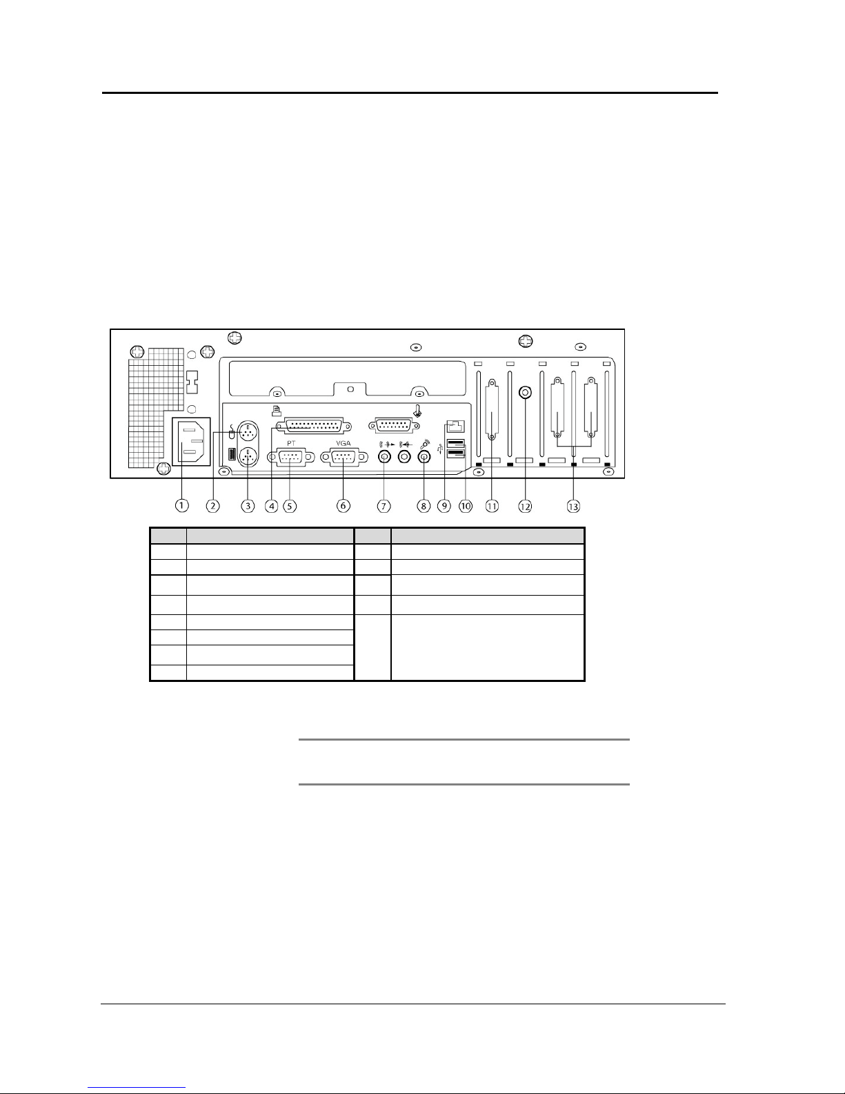
Back Panel
EDNS-4000 - 4 CH/8 CH/16 CH (The picture below is EDNS-4000-16CH.)
No. Name No. Name
1 Power Connection Circuit 9 LAN Port
2 Mouse Port 10 USB Port
3 Keyboard Port 11 Alarm input/output Port
4 Printer Port 12 Spot Monitor Output / RCA Jack
5 PTZ Controller Port / RS-232C
6 PC Monitor Output
7 Speaker Output / Line Out
8 Microphone Input
13
Image Input / D-Sub
EDNS-4000 4 CH: 4ch 1ea
EDNS-4000 8 CH: 8ch 1ea
EDNS-4000 16 CH: 8ch 2ea
Power Connection Circuit
Connect the power cord enclosed.
Note
Before connecting the power, convert the power switch,
AC110V ~ 120V ->115, AC220V~240V->230V, depending on
the power voltage on the power socket.
Mouse Port
Connect the mouse enclosed.
Keyboard Port
Keyboard can be connected (Option).
LAN Port
In case of remote monitoring, connect the LAN cable in the RJ-45 jack
connector.
Network has to be LAN (Local Area Network), Internet, or exclusive line
of TCP/IP basis 10/100BASE-TX Ethernet.

DigiOpG2 Digital Video Recorder for 4-8-16 cameras Page 13
3040-00057
USB Port
Connect exterior CD-RW driver of USB interface. Only approved USB
CD-RW models by manufacturer can be used.
Printer Port
Connect the printer when printing the searched image.
PTZ Controller Port / RS-232C
When PTZ controller is connected as 1:1, it will be connected directly to
RS-232C. Normally use RS422 or RS-485, when several PTZ controllers
are connected at once. To do this, an adapter (option) is required to
transfer RS-422/485 signal to RS-232C signal.
PC Monitor Output
Connect PC monitor to view the image output.
Speaker Output / Line Out
The output signal is line level. To expand the output signal, there is a
need for amp in the middle.
Microphone Input
Input voice is synchronized in image of the channel 1. When the voice
signal is line level, connect to Line in jack at the left of the Microphone
Input jack.
Alarm input/output Port
Image Input / D-Sub
Connect the cables from the alarm devices to the Alarm I/O terminal.
Connect cables from the terminal with relay outputs to the external
equipment.
Connect the plug of BNC cable to recording camera. In case of 4 CH,
connect 1~4 channel cameras to the BNC Jack of 4ch BNC-to-D-Sub. In
case of 8 CH, connect 1~8 cameras to the BNC Jack of 8ch BNC-to- DSub. In case of 16 CH, connect 1~16 cameras using 2 cables of 8ch BNCto-Dub.
Spot Monitor Output/ RCA
Jack
Connect a CCTV monitor to the RCA Jack. The CCTV monitor can display
the same image(s) as seen on the PC Monitor, but without the user
menus. The screen mode of the spot monitor always follows the screen
mode on the PC monitor.

DigiOpG2 Digital Video Recorder for 4-8-16 cameras Page 14
3040-00057
2.3. Installation EDNS4000
This section describes how to hook up DigiOpG2 to peripheral devices. Be sure to turn off the power of DigiOpG2
before making any connections. (The connections might vary according to the components of product model and the
chosen specifications of the user. The below diagram is for 16 CH.)
No. Name No. Name
1 Power Cord 9 LAN Port
2 Mouse Port 10 USB Port
3 Keyboard Port 11 Alarm input/output Port
4 Printer Port 12 Spot Monitor Output / RCA Jack
5 PTZ Controller Port / RS-232C
6 PC Monitor Output
7 Speaker Output / Line Out
8 Microphone Input
13
Image Input / D-Sub
EDNS-4000 4 CH: 4ch 1ea
EDNS-4000 8 CH: 8ch 1ea
EDNS-4000 16 CH: 8ch 2ea
Line Out

DigiOpG2 Digital Video Recorder for 4-8-16 cameras Page 15
3040-00057
Power Cord
Connect the power cord enclosed.
Note
Before connecting the power, convert the power switch on the
power socket depending on the power, AC110V ~ 120V >115, AC220V~240V->230V.
Camera
Monitor
Microphone and Speaker
DigiOpG2 is compatible with PAL or NTSC camera. To get high quality
image, check the power of the whole system and the safety of the
ground construction. Also, adjust the lightening and focus or iris of the
camera properly.
Note
The camera image cannot be recorded properly when the PTZ
control signal is mixed with camera signal. In this case, connect
after separating the control signal.
EDNS-4000 supports both PC and spot monitor. Connect the analog TV
monitor to spot monitor output, and the camera images of the selected
channels will be displayed in sequence. Spot monitor output is always
displayed as full screen, and is independently controlled. For more
detailed information, refer to “Setting Customized Functions-> Select
Recording.”
1-Channel voice recording is possible in EDNS-4000, and the recorded
voice is synchronized in the channel 1. Connect the Microphone signal
for voice recording in the Microphone input jack. When voice signal is
line level, then connect to Line-in jack placed in the left of the
Microphone input jack. Also, connect with the speaker to listen to the
replay of recorded voice. Output signal is line level. Therefore, to amplify
the output signal, amp for speaker is necessary. Refer to “Viewer>Other Settings” for volume control.
Sensor and Alarm
Alarm I/O Terminal, which is an option, is needed to use the sensor input
and alarm output. Connect the terminal’s cable to the alarm
input/output port. Then connect each sensor and alarm wiring to the
corresponding terminal port. Sensor and alarm devices can be
connected at maximum 4 for both.
Note
Sensor and alarm are activated by relay switch. It can be
connected to either N/O (Normal Open) or N/C (Normal Close)
type and the user has to set the sensor according to each of
them. To recognize the sensor input the contact has to be
closed for at least 0.5 seconds. Please make sure that the
current of the external relay does not exceed the specifications
of the relay.
Network
Connect to network (Internet, LAN) for remote monitoring using Agent
series remote software. The IP address must be fixed and the dynamic IP
address allocated by DHCP cannot be used. Contact your dealer or
network supervisor if you need any assistance.
Printer
High quality color printer and appropriate paper type are required to
print at highest quality. Refer to “Viewer->Other Setting” for
information on the corresponding printer drive install.

DigiOpG2 Digital Video Recorder for 4-8-16 cameras Page 16
3040-00057
3. EDNS5000/EDNS6000 SYSTEM STRUCTURE AND INSTALLATION
The DigiOpG2 EDNS5000/6000 DVR series is designed for easy installation and use. The following pages show how
to install the DVR and provide some basic user instructions to use the DVR as quickly as possible.
Unpacking.
Your DigiOpG2 system and its accessories come securely package. When you unpack your system, please be
sure to check all of the following items that should be included.
• DigiOpG2 Main Unit
• CD with DigiOpG2 WebAgent software.
• Power cable
• Installation manual
• Quality guaranteed Certificate
• 4 x Rubber Foot
• Mouse
• Key
Carefully inspect each component to make sure nothing is missing or damaged.
If any of these items is missing or damaged, notify your dealer immediately.
DigiOpG2 Digital Video Recorder for 4-8-16 cameras Page 17
3040-00057
4. Identification of Controls and Connectors
4.1. Front Panel EDNS5000/EDNS6000
1. Use the Keypad to input numbers.
The Keypad with numerical keys is used to access the operation keys, activate the user interface on the
Monitor, entering password and selection of camera channel. The keypad can also be used for other functions,
depending on the situation.
If the front Door is closed, please unlock by use of the key.
If the power is OFF please input password. The system will now start and be operational in a few seconds.
If the DigiOpG2 system is recording, the numerical keys can be used to select camera channels (Channels over
no. 10 use + input the desired channel numbers)
If DigiOpG2 system is recording while in PTZ mode, the numerical keys can be used to call preset positions for
the selected camera.
2. Camera LED
The camera symbols will be lit if the actual cameras are connected to the system.
3. Floppy disk drive
For storing video images in JPEG/BMP/MPEG format.
4. CD-RW
For storing or retrieving data information from Read/Write CD media. The CD-RW is optional. DVD could also
be installed (optional).
5. Power LED.
Indicates that there is power applied to the unit.
6. Remote Transmission Indicator
Indicates an external user have gained access to the DigiOpG2G2 from a remote destination using the
WebAgent, Remote Agent or NetAgent software.
7. Sensor Indicator
Indicate that an alarm have been activated by one of the sensors connected to the system.
12 3 4
56789101112 1314151617 18 19 20

DigiOpG2 Digital Video Recorder for 4-8-16 cameras Page 18
3040-00057
8. Recording condition Indicator
Indicates that the system is recording.
9. Reset Button (Caution!)
The DigiOpG2 DVR has a built-in safety feature. When the system is shut down abnormally, the Reset Button
must be pushed in with a sharp pen for at least a second to start the system properly (This prevents the hard
disk and other sensitive electric parts from getting unexpected electric shock).
10. Power button
Press the power button to turn the power off.
11. Pan/Tilt Buttons
These four buttons are used to move a Dome or PTZ camera. Before using, select the desired PTZ camera in full
screen mode. PTZ functions do not work in split screen mode.
12. Preset Button.
This buttons is used to call a pre-programmed position for a PTZ camera. Press the Preset key and then the
preset number (See numerical keypad described in point 1). Before using, select the desired PTZ camera in full
screen mode. PTZ functions do not work in split screen mode.
13. Zoom Buttons.
These two buttons are used to control the zoom lens of any connected PTZ cameras. Press the +/- key to zoom
wide or Narrow. Before using, select the desired PTZ camera in full screen mode. PTZ functions do not work in
split screen mode.
14. Focus Buttons.
These two buttons are used to control the zoom lens of any connected PTZ cameras. Press the +/- key to focus
near or far. Before using, select the desired PTZ camera in full screen mode. PTZ functions do not work in split
screen mode.
15. Button to convert to full screen.
Covert or disband to the Full Screen Mode.
16. Select Screen Split Mode
Select the present recording screen from 1,4,9,10,13,16 Screen Mode. Press the button once whenever you
want to change the Screen Mode according to the order above.
17. See Next
Press this button to see the next channel group’s image on the present screen.
18. Speaker (not used).
19.Front Door
Insert the key and unlock the front door. Now there is access to the user keys. Use the number keys to input
the password in order to activate the system and display the main operation menu on the Monitor. To protect
the System from unauthorized persons, lock the front door after use.
Method to input or change password.
The default Password is “1 2 3 4”.
Ex) P → 1 → 2 → 3 → 4 (You will hear 2 beeps)
To change Door Password:
P → P → P (Password Change Mode)
→ 1 → 2 → 3 → 4 (Input present Password)
→ 7 → 7 → 7 → 7 (Input new Password)
→ 7 → 7 → 7 → 7 (Check Password Input).

DigiOpG2 Digital Video Recorder for 4-8-16 cameras Page 19
3040-00057
Caution: The Password doesn’t change if there is no input for more than 2 seconds. The Password will change
back to 1,2,3,4, if there is power shut down. So please check the Password after changing it.
In case you forget the Door Password, do as follows and you could find out the present Door Password.
First, turn off the power to the System and then pull out the mains cable.
Connect the power cable to the system while pressing “P” on the Number Panel.
Stop pressing “P” on the Number Panel when you hear the Beep sound twice after 5 seconds.
DigiOpG2 program starts and a box appears, asking for DigiOpG2 manager’s password. (The System Shutdown
if it is cancelled)
A box appears showing the adjusted Door Password after checking the manager’s password. (The System
Shutdown if the manager’s password is not correct for more than 3 times).
Check the actual Door Password and then close the Box.
20. Handle.
The unit is equipped with handles on the front and rear. These handles may be used for easy installation and
transportation.
DigiOpG2 Digital Video Recorder for 4-8-16 cameras Page 20
3040-00057
Rear Panel
01. BNC connectors for camera signals.
02. Alarm sensor inputs.
03. Alarm outputs for control of siren, light etc.
04. PC Monitor output.
05. CCTV monitor output.
06. Mains Power socket.
07. Pan/Tilt Port (RS232). For RS485 output use Ernitec EDNSPTZ converter
08. Printer Port.
09. Ethernet connector. For direct connection to LAN/WAN Network.
10. Not used.
11. SCSI Port (Optional.) Back-up system connection RAID storage.
1 2 3 4 5
6 7 8 9 10 11
DigiOpG2 Digital Video Recorder for 4-8-16 cameras Page 21
3040-00057
5. Connecting the EDNS5/6000 Digital Video Recorder.
This section describes how to connect the DigiOpG2 DVR to peripheral devices. Be sure to turn off the power
before making any connections.
Camera
Be sure to match the type of cameras to the corresponding system. To get the better image, use 75 ohms
coaxial cable and make connections firmly.
Note: Use the DigiOpG2 controller to operate the Camera’s location, zoom or focus point with the
operation of other parts like the siren, alarm and etc. Refer to the detail explanations later in this manual.
Monitor
Basically, the DigiOpG2 DVR provide dual display mode. The camera images can be seen in on a normal
CCTV monitor or on a PC monitor. The PC monitor must have a resolution of 800x600 and frequency of
60Hz or more.
Sensor input and control output.
The connector for alarm sensors placed on the rear panel of the DigiOpG2G2 allows connection of up to
16 external sensors and have 8 control outputs (relays). The sensor input accept either N/O or N/C relay
contact. Any sensor input can trigger one of the 8 alarm outputs. These outputs are used to control
external equipment, such as Light, Siren, etc.
Printer
To print out the images searched by the DigiOpG2 Viewer, you need to install the corresponding printer
drive before using the printer. Refer to the section “adding printer” later in the operation manual.
Network
Connect the DigiOpG2 DVR to the network (LAN, WAN etc.) and transmit images to the DigiOpG2
NetAgent software Series. Please contact your dealer or network supervisor if you need any assistance.

DigiOpG2 Digital Video Recorder for 4-8-16 cameras Page 22
3040-00057
Turning “ON” the DigiOpG2 DVR
Make sure all connections of your system were firmly made.
Turn on the power of all connected appliances.
Plug the power cable of the DigiOpG2 DVR into the wall outlet.
Press the password on the number panel.
The DVR starts.
The Monitor shows the main menu.
Login to operate.
Turning “off” the DigiOpG2 DVR
First, open the door on the front panel by using the key.
Press the power button to turn off the power and then close and lock the door.
DigiOpG2 Digital Video Recorder for 4-8-16 cameras Page 23
3040-00057
6. EDNS7000 SYSTEM STRUCTURE AND INSTALLATION
The DigiOpG2, model EDNS7000 Digital Video Recorder is designed for easy installation and use. The following
chapter describes how to connect the DVR and provide some basic user instructions to use the DVR as quickly as
possible.
Unpacking.
When you unpack your DigiOPG2 system, please be sure to check if all the following items are included.
• DigiOpG2 Main Unit
• CD with DigiOpG2 Remote Agent software.
• Power cable
• Installation manual
• 4 x Rubber Foot
• Mouse
• Key
• 19” rack mount x 2
• cables for video input 1-8 and 9-16 (only 16 ch vers)
Carefully inspect each component to make sure nothing is missing or damaged. If so, notify your
dealer immediately.
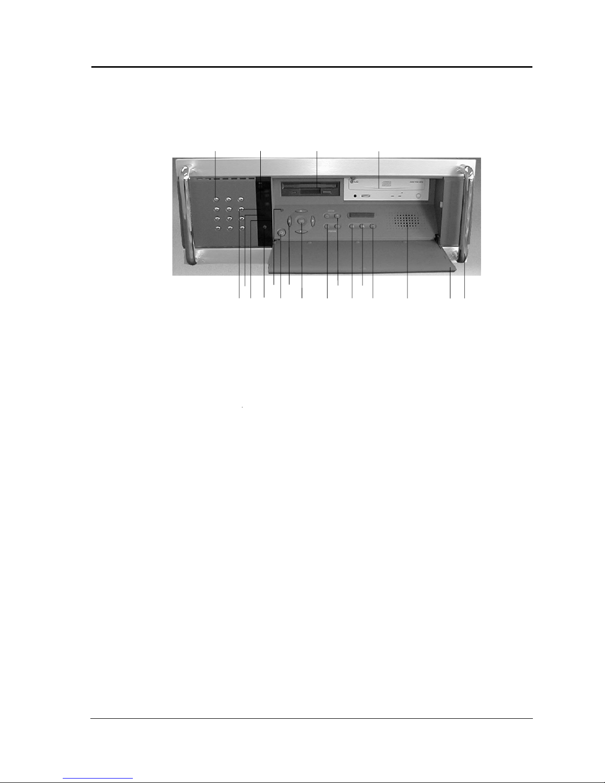
7. Cabinet and connector layout.
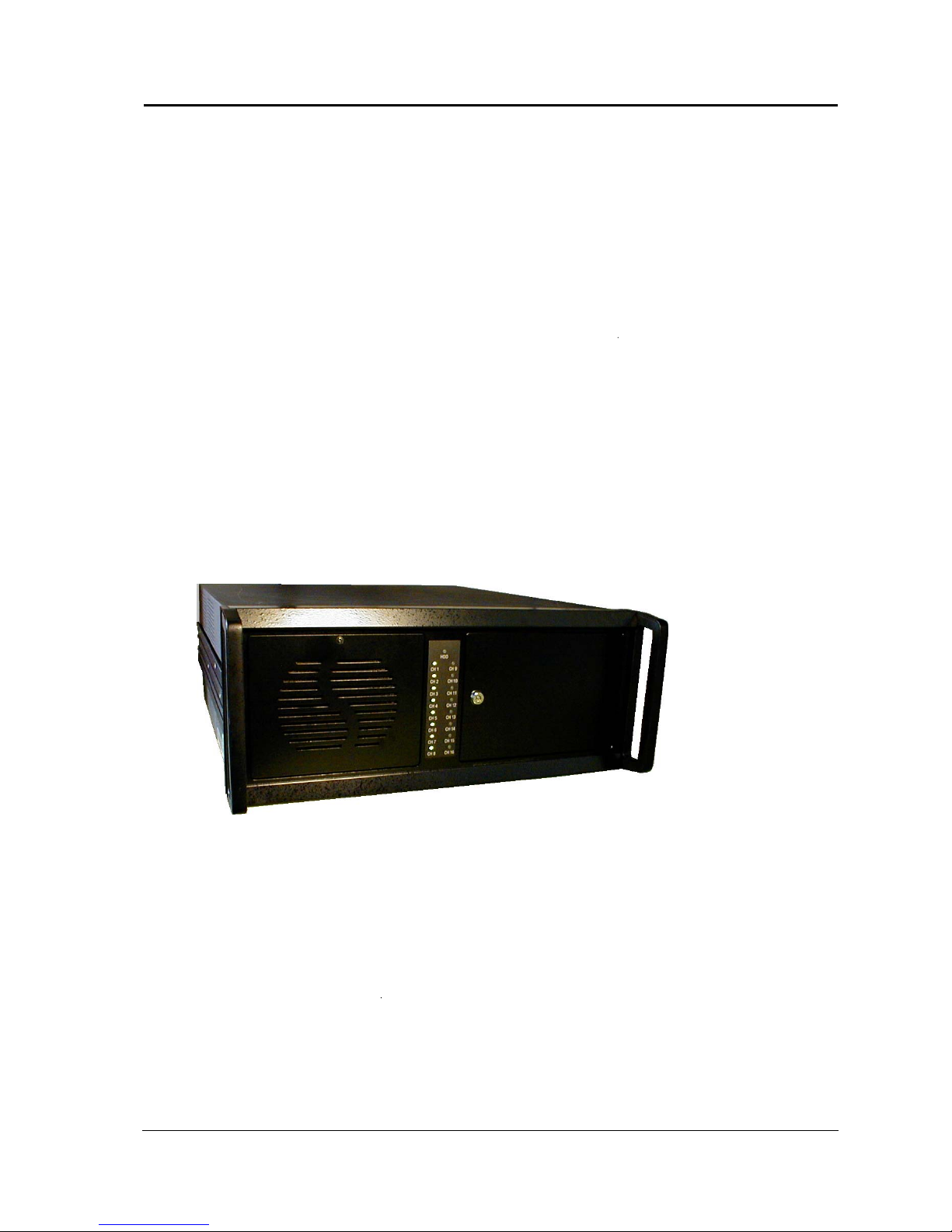
Front Panel of EDNS7000 DVR
1. Front Door
If the front Door is closed, please use the key to unlock. Behind the door you will find the CD-RW or DVD drive
(optional) for back-up of video data. Data can be in the format DSF/JPEG/BMP/MPEG. You will also find the
power On/Off button and 2 x USB ports
2. Indicator LED
The camera symbols will be lit if the actual cameras are connected to the system. The LED marked with HDD
indicates when video data is written to the Hard-disc.
3. Handle. The unit is equipped with handles on the front and rear. These handles may be used for easy
installation and transportation.
DigiOpG2 Digital Video Recorder for 4-8-16 cameras Page 24
3040-00057
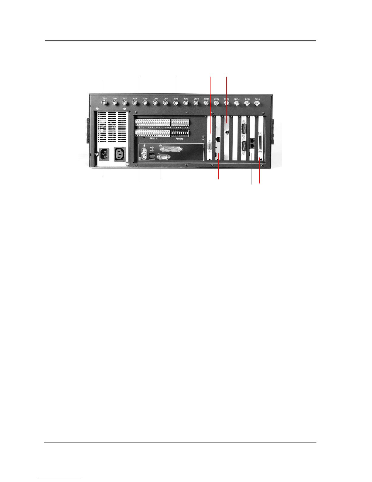
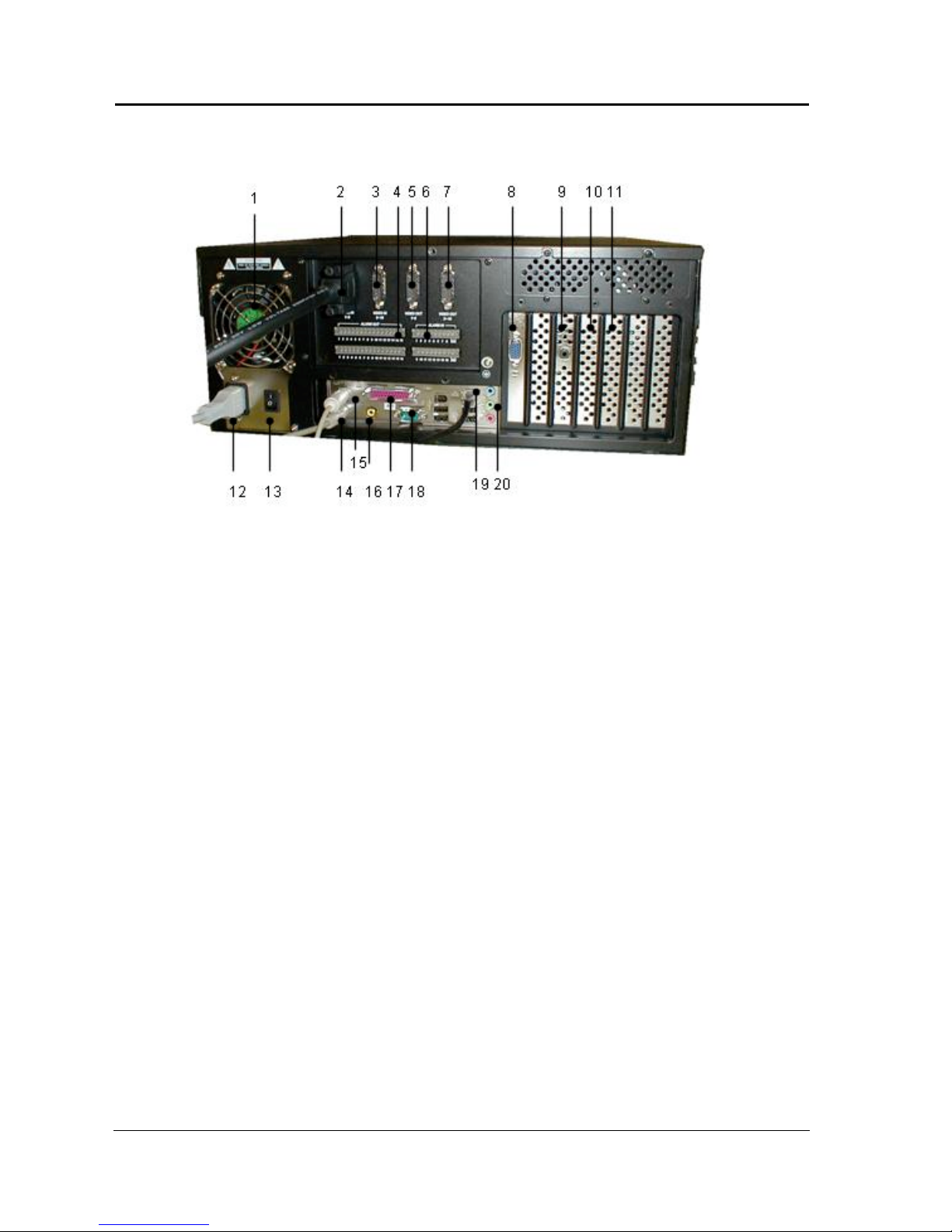
Rear view
01. Ventilator
02. Camera inputs 1-8
03. Camera inputs 9-16
04. Control outputs 1-16
05. Loop outputs 1-8
06. Alarm inputs 1-16
07. Loop outputs 9-16
08. VGA Monitor output
09. CCTV monitor output
10. Optional slot for SCSI (RAID storage) or Sound card
11. Optional slot for SCSI (RAID storage) or Sound card
12. Mains connection
13. Mains On/Off
14. Mouse connector
15. Keyboard connector (not supplied)
16.
17. Printer port
18. Pan/Tilt Port (RS232). For RS485 output use Ernitec EDNSPTZ converter
19. Ethernet connector. For direct connection to LAN/WAN Network.
20. Loudspeaker

DigiOpG2 Digital Video Recorder for 4-8-16 cameras Page 25
3040-00057
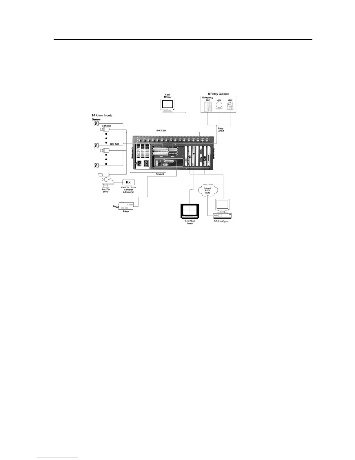
8. Connecting the EDNS7000 Digital Video Recorder.
This section describes how to connect the DigiOpG2 DVR to peripheral devices. Be sure to turn off the power
before making any connections.
Camera
Be sure to match the type of cameras to the corresponding system. To get the better image, use 75 ohms
coaxial cable and make connections firmly.
Note: Use the DigiOpG2 controller to operate the Camera’s location, zoom or focus point with the operation
of other parts like the siren, alarm and etc. Refer to the detail explanations later in this manual.
Monitor
Basically, the DigiOpG2 DVR provide dual display mode. The camera images can be seen in on a normal CCTV
monitor or on a PC monitor. The PC monitor must have a resolution of 800x600 and frequency of 60Hz or
more.
Sensor input and control output.
The connector for alarm sensors placed on the rear panel of the DigiOpG2G2 allows connection of up to 16
external sensors and have 8 control outputs (relays). The sensor input accept either N/O or N/C relay contact.
Any sensor input can trigger one of the 8 alarm outputs. These outputs are used to control external
equipment, such as Light, Siren, etc.
Printer
To print out the images searched by the DigiOpG2 Viewer, you need to install the corresponding printer drive
before using the printer. Refer to the section “adding printer” later in the operation manual.
Network
Connect the DigiOpG2 DVR to the network (LAN, WAN etc.) and transmit images to the DigiOpG2 NetAgent
software Series. Please contact your dealer or network supervisor if you need any assistance.
Turning “ON” the DigiOpG2 DVR
Make sure all connections of your system were firmly made.
Turn on the power of all connected appliances.
Plug the power cable of the DigiOpG2 DVR into the wall outlet.
The DVR starts.
The Monitor shows the main menu.
Login to operate.
Turning “off” the DigiOpG2 DVR
First, open the door on the front panel by using the key.
Press the power button
DigiOpG2 Digital Video Recorder for 4-8-16 cameras Page 26
3040-00057
9. OPERATIONS OF THE DVR.
9.1. System Operations
Power Connection
Check the connection of the peripheral device of the system and
connect the power. When the power cord of the DigiOpG2G2 is
connected, system program will start.
To end the system, complete the booting and press the power button of
the front panel. When the user presses the power button for too long,
the power of the product will be completely blocked and it will start
Auto-Recovery while booting.
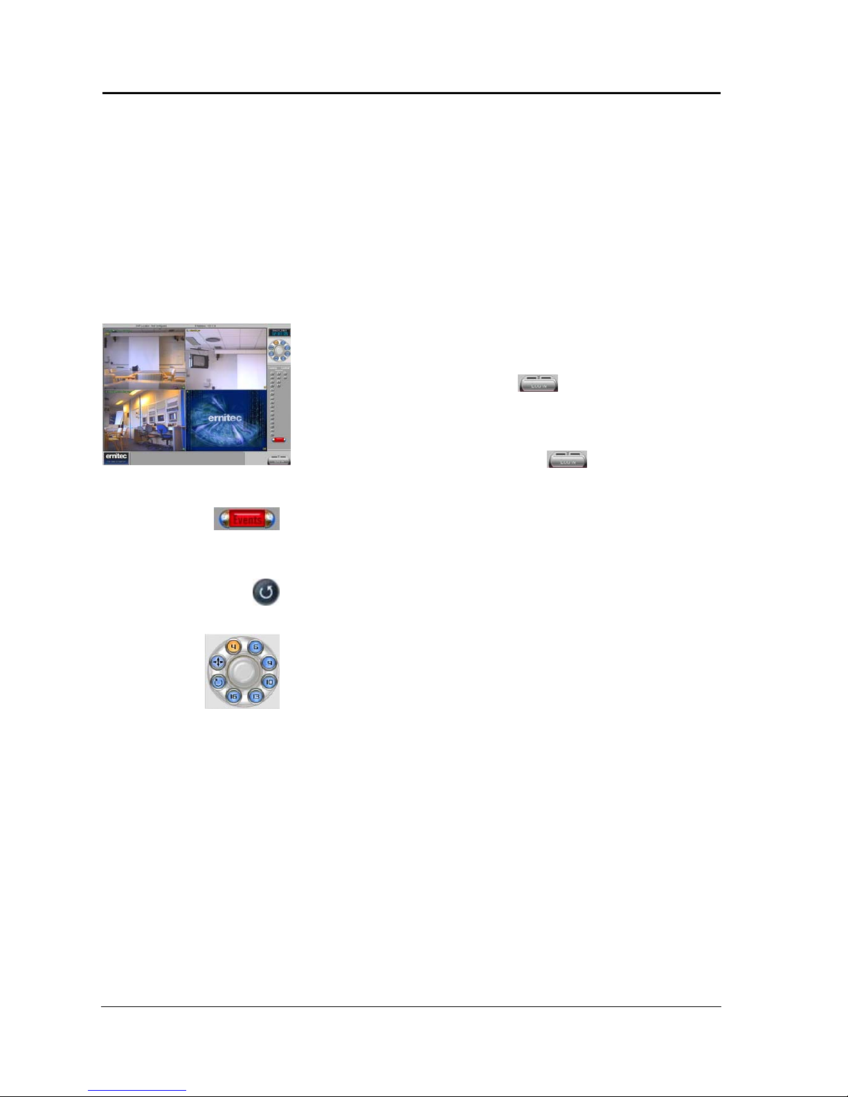
Start Program
The main program will start right away when the power of the
DigiOpG2G2 comes in.
To use the buttons in the main screen, log in as the administrator user.
Input administrator ID and password by clicking [
] button
located at the right bottom of the main screen.
Administrator’s ID is set as “admin” when logging in for the first time,
and the password is not set. Refer to “Setting Customized Functions” for
more detailed information.
Menu buttons cannot be used after logging out when [
] button
is pressed.
Connect System Peripheral Device
When remote transmission and sensor is functioning well, each button
shown in the picture will activate. (Refer to "Screen Layout” for more
detailed information)
Display Division Rotation
By pressing this button, the screen automatically alternates on selected
screen-split. When selected in 1-channel, then depending on the time
setting, automatically alternates by 1-channel, and when selected in 8channels, according to the time setting, the screen alternates by 8channels.
Split Screen Mode
The current recording screen can be seen in several screens (4, 6, 9, 10,
13, 16 screens) or by only one screen. Whenever the user presses each
button, the screen will change to 1, 4, 6, 9, 10, 13, 16 screen.
DigiOpG2 Digital Video Recorder for 4-8-16 cameras Page 27
3040-00057
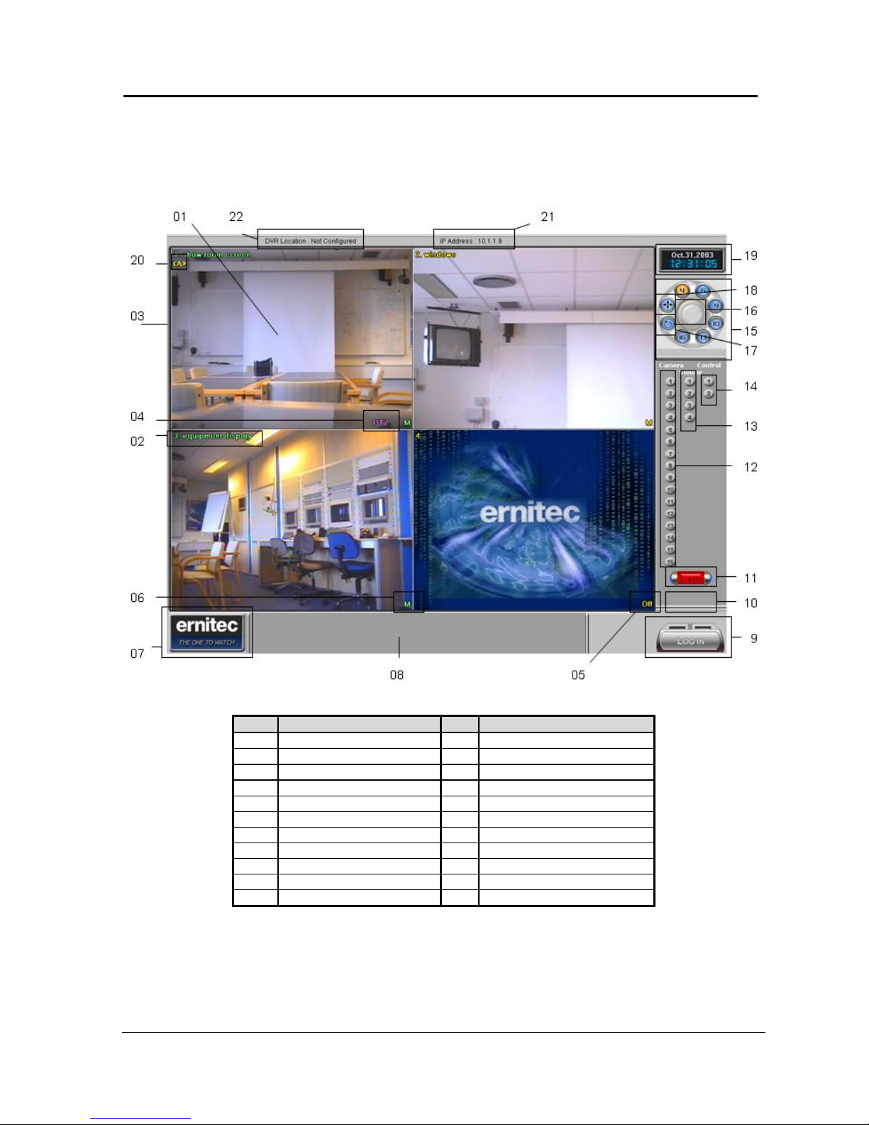
9.2. Screen Layout
The screen layout of DigiOpG2G2 is user-friendly to allow even novice users to easily learn and use the system. The
following is the layout of the DigiOpG2G2 main screen.
No. Name No. Name
1 Current recording screen 12 Camera no. & recording indicator
2 Camera location no. & text. 13 Sensor / alarm inputs
3 Current recording screen 14 Controls/Auxiliaries
4 PTZ camera indicator 15 Display mode / Split-screen mode
5 Recording status indicator 16 Current channel layout
6 Recording status indicator 17 Rotation
7 Ernitec help logo 18 Full screen toggle
8 Scrolled text 19 Time & Date
9 Tools menu 20 Audio recording indicator
10 Remote status indicator 21 IP address
11 Sensor indicator 22 DVR location
DigiOpG2 Digital Video Recorder for 4-8-16 cameras Page 28
3040-00057
9.3. Detail Functions
The following are the functions for each button. User login is required to use these buttons.
Current Recording Screen
Displays the image of connected camera or recorded images. In case the
camera is not connected, the vacant screen displays the logo of the
product.
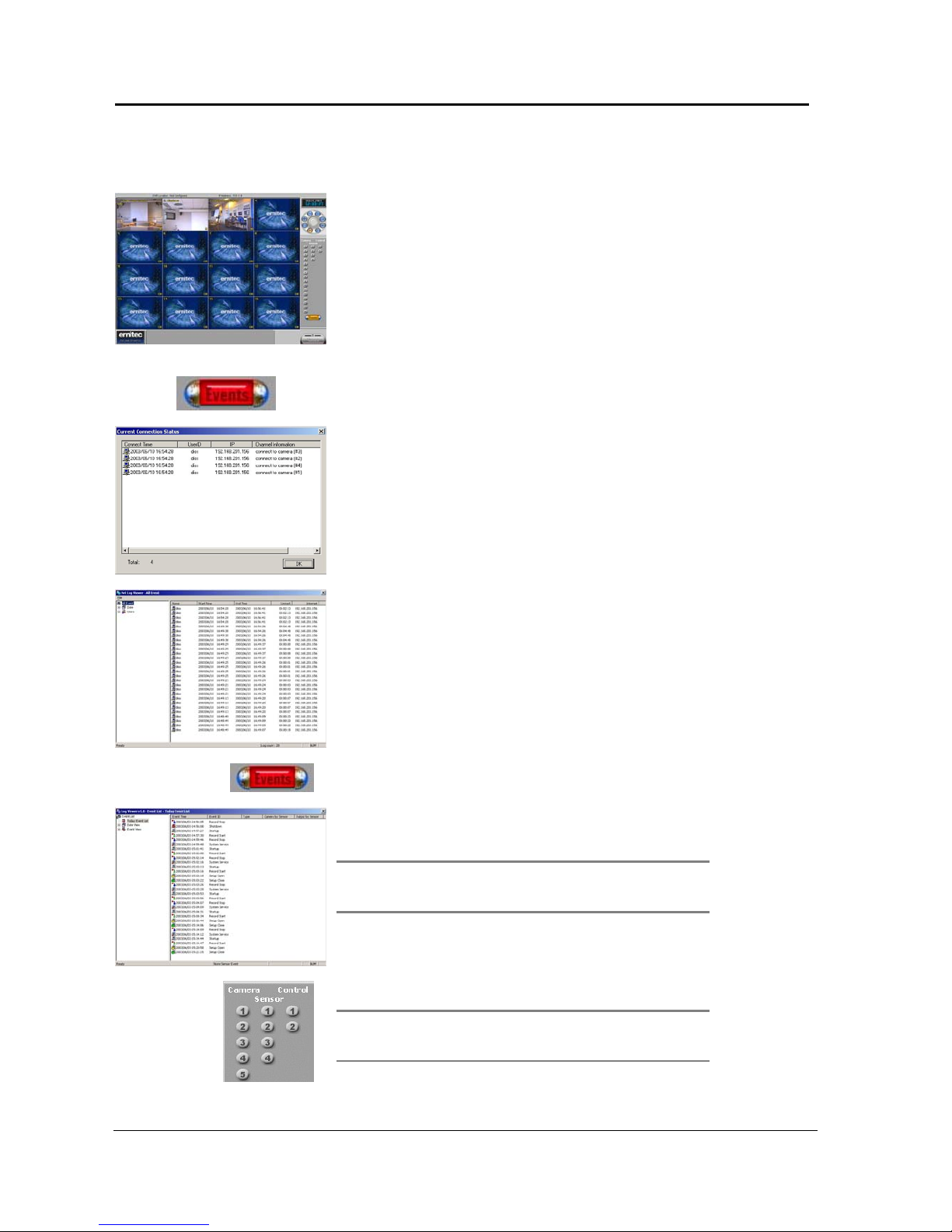
Transmission Status Indicator
Transmission status indicator flashes while connecting with remote
surveillance Agent Series to indicate that it is presently transmitting.
Shows information of the connected user when the corresponding
button is clicked while the Agent Series is connected.
When the system is not connected, double click the indicator to view
full connection history, the Net Log Viewer. It shows 200 most recent
histories.
Sensor Indicator
The indicator flashes when the alarm sensor is indicated. All sensor
inputs are only active when “Setting Customized Functions->Sensor>Enable Sensor and Control” category is selected.
Note
Double click the sensor indicator with the left side of the
mouse to start the Log Viewer. The log viewer shows the list of
occurred events by date and type of the event.
Camera Number and Recording Indicator
These icons numbered 1-16 are the camera number indicators that flash
when there is motion present with the associated camera.
Note
When all channels are in “Watch Mode,” then they are not
recorded. However, be cautious since the on-screen-recording
indicator might be activated.
DigiOpG2 Digital Video Recorder for 4-8-16 cameras Page 29
3040-00057
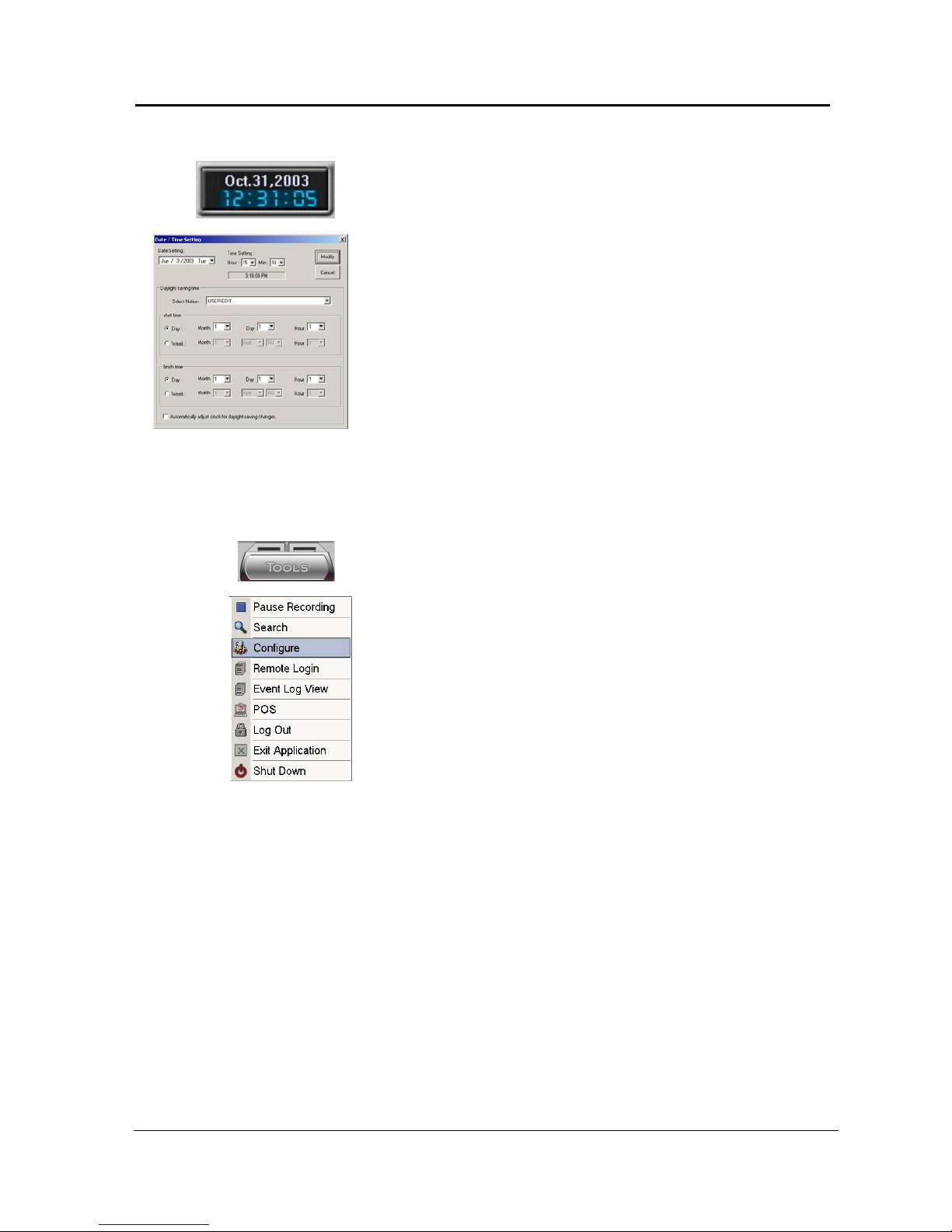
Date
Date is displayed in “month, date, year” format. Click this part with the
mouse to change the date/time.
To change the date and time, click on the figures that show date or time
on the DigiOpG2G2 main screen and then enter proper password.
Administrator can change the setting, make any changes then click
[Modify] button.
Time
Time is displayed in “hour, minute, second” format.
Click this part with the mouse to change the date/time.
Select the desired date and time. Then, click [Modify] button.
DigiOpG2G2 stops recording automatically when date/time setting has
been changed. Click [Start Recording] button to start recording the
images.
Daylight Saving Time
To not use the daylight saving, do not check “Automatically adjust clock
for daylight saving changes.”
To set up the daylight saving, choose “Select Nation-> USER EDIT.”
Then, set up the time and date. When the user selects the country in
“Select Nation,” time and date will change automatically depending on
the country.
TOOLS.
Click on the “TOOLS” key to enter the User and configuration menus.
Pause Recording
Stop recording of all the live images. Click [Pause Recording] button and
a warning message will appear. When the recording does not start for
more than 5 minutes, the recording will start again automatically.
Start Recording
The DVR always starts to record automatically. If the recording has been
stopped during setup, please click on the “Start recording” key in the
Tools menu.
Search function
To start the viewer program click on the SEARCH key. It is now possible
to search the recorded images.
(Refer to “Viewer” section for more detailed information
Configure
Click the “Configure” key to enter the function setup. A selection
screen will appear for setting recording, image quality, desired recording
time, motion sensitivity etc.
DigiOpG2 Digital Video Recorder for 4-8-16 cameras Page 30
3040-00057
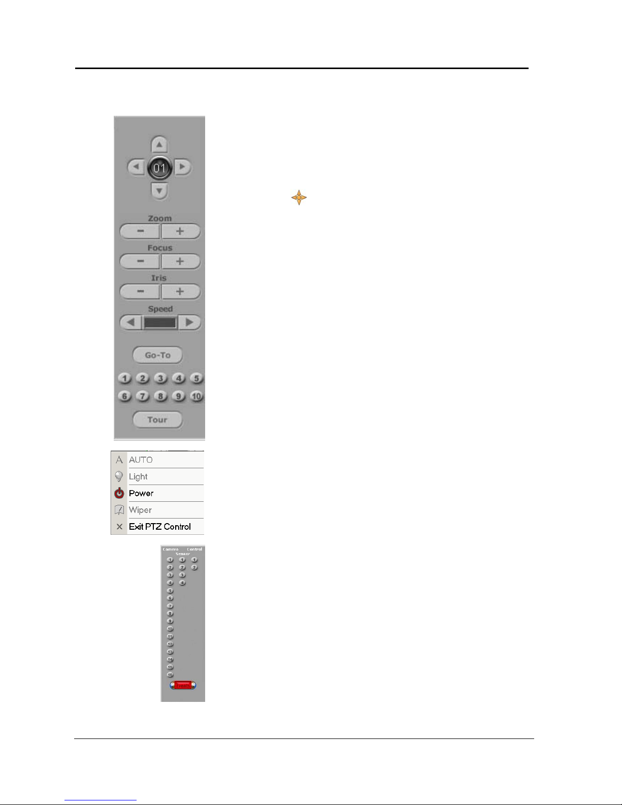
Camera Control Button
If a camera has PTZ functions, this will be shown in the lower left corner
of the camera picture. The controller enables users to control Pan/Tilt,
zoom in/out, and screen adjustment functions through the camera. The
control panel for camera control is on top right of the screen.
The “Virtual Joystick (
)” appears with control panel as the picture
on the left when the right button of the mouse is clicked. Move the
mouse according to the direction of the pointer, which appears on a
chosen image screen. Then the image of screen will move without
clicking the button of the control panel.
The following are the explanations for each button of the controller.
Pan/Tilt
Camera with installed P/T controller will move in each direction while
the button is pressed down (The Pan controls the right & left direction of
the camera and the Tilt moves the camera up & down).
Zoom (In/Out) Button
The size of the image will be enlarged or reduced while the button is
pressed down.
Focus In/Out
Objects on the screen will be focused while the button is pressed down.
Iris Open/Close
Adjust the brightness of the image by opening or closing the iris. More
the iris is opened, image becomes brighter, more closed, image
becomes darker.
Speed
Control the movement speed of the camera.
Preset 1-10
Instantly moves the camera to the corresponding preset location
whenever a button is pressed. (Refer to “Camera Control” for more
detailed information)
Tour
Click this icon to cycle through your predetermined presets. (if
supported in the camera).
PTZ Tools
Click on the Tools menu icon to get the PTZ tools.
Auto – Auto Pan Feature (must be supported by PTZ camera).
Light – Activates a light on a PTZ Camera (must be supported by PTZ
camera).
Power – Turns Power On/Off of the PTZ Camera (must be supported by
PTZ camera).
Wiper – Activates a wiper installed on the PTZ Camera. (must be
supported by PTZ camera).
Channel
Like TV channels, switches fast and conveniently between several
channels to view images from each camera. When you click Number 2
button, images from camera 2 can be seen.
 Loading...