

HD16 Series 16 channel Encoder Quick Setup Guide
This guide provides instructions to initially setup DIGIOP’s HD16
Encoder. This supports:
• Self-adaptive HD-TVI / HD-CVI / AHD / CVBS signal input
• H.265+/H.265/H.264+/H.264 encoding
• Simultaneous HDMI / VGA / CVBS monitor output
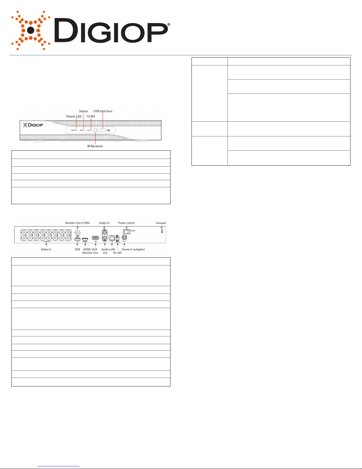
Encoder Front Panel
Item: Usage:
Power LED Indicator turns green when Encoder is powered up.
TX / RX Indicator blinks green when network connection
is functioning properly.
IT Receiver Sensor for the remote control.
USB Interface This port can be used for a USB mouse for USB
flash memory devices.
Encoder Back Panel
Item: Description:
VIDEO IN BNC connectors for camera video channels in.
Number of channels is dependent on the model
of Encoder.
Monitor Out (CVBS) BNC connector for CVBS video monitor.
AUDIO IN RCA connector for audio in cable.
On/ OFF switch Switching for powering encoder on and o.
USB Use this port for a USB mouse or USB memory
device such as a flash drive or DVD burner. A USB port is
also located on the front panel.
HDMI Connector HDMI monitor cable.
VGA Connector VGA monitor cable.
AUDIO OUT RCA connector for audio out cable.
LAN RJ-45 connector for Ethernet drop cable.
RS-485 terminations Connector for RS-485 devices. Connect the D+ and the
D- terminals to T+ and T- of PTZ receiver respectively.
12 Vdc Plug for 12 Vdc power adapter.
GND terminal Ground terminal post.
Mouse Control
A standard 3-button (le/right/scroll-wheel) USB mouse can also be
used with this encoder. To use a USB mouse:
1. Plug the USB mouse into either the front panel or back
panel USB connector.
2. The mouse will be automatically detected. If the mouse is
not detected, the mouse may not be compatible. Please refer
to the recommended device list from DIGIOP.
Action: Eect:
Left click Single click: Live view
Menu: Select and enter.
Double click: Live view. Switch between
single-screen and multi-screen.
Tamper-proof, privacy mask and motion detection:
See target area.
Digital zoom-in: Drag and elect target area.
Live view: Drag channel / time bar
Right click Live view: Show menu.
Menu: Exit current menu to upper level menu.
Scroll Wheel Scroll up: Live view: Next screen.
Menu: Previous screen.
Scroll down: Live view: Next screen.
Menu: Next item.
Installing the System
Step 1. Getting Started: Unpacking the Equipment
What’s in the box
Your system includes:
• DIGIOP HD16 Series encoder
• USB mouse
• HDMI cable
• Power adapter for Encoder
• Ethernet cable
Remove the equipment from its packaging and place it on a flat, clean
surface. Inspect each item. If any visible damage is present, contact
your supplier for a replacement. Verify that your order is complete.
What you need
Although each security system installation is dierent, most require the
following items not included with your system components:
• Cameras and cables compatible with the encoder. The Video
Input ports on the back panel support most analog CCTV
camera brands and HD-TVI, AHD and 960H analog
cameras (up to 2MP cameras.)
• Tools to install the cameras and route power, video and
audio cables
• Fasteners to attach the cameras to the mounting surfaces,
caulking.
• VGA or HDMI compatible computer monitor to connect to
the Encoder (An HDMI cable is provided.)
• Uninterruptible power supply (UPS) is recommended. This
device is used to ensure system stability during voltage
surges, sags, and outages. If a UPS is not available, a power
strip with strong surge protection is highly recommended.
Step 2. Install the Encoder
For the following steps, refer to the back panel photo above for the
location of the connectors.
1. Place the Encoder in a location that is secure, well ventilated and
clean. The Encoder should be positioned such that the back panel
connectors are accessible and the ventilation holes on the sides are
not blocked.
2. Connect the ground terminal on the back of the Encoder to an
earth ground. Refer to local codes for proper grounding.
Step 3. Install a monitor, mouse, power
For the following steps, refer to the back panel photo for the location of
connectors.
1. Install and setup your monitor in accordance with the instructions
provided with the monitor. Do not power it on at this time.
2. Cable the HDMI or VGA connector to your monitor’s VGA or HDMI
input. The HDMI interface provides the best performance.
3. Plug the mouse into the USB connector on the front or back of the
Encoder.
4. Plug a drop cable from your local area network (LAN) into the RJ45
LAN connector on the back of the Encoder.
5. Connect the power cord to the power connector on the back panel
of the encoder, and then into a UPS (recommended) or surge protector.
Step 4. Install cameras
Install your security cameras. Always follow the installation instructions
provided with the camera.
Step 5. Connecting it together – initial system setup
1. Plug the coaxial cables from the cameras into the BNC camera
input connectors on the back of the Encoder.
2. Power on your cameras.
3. Power on the Encoder using the power on / o switch on the back
panel.
4. Power on the monitor.
Note: Some monitors have multiple inputs including VGA, HDMI,
BNC, etc. If you are using this kind of monitor, congure your monitor to
display the input connected to your Encoder (HDMI or VGA).
Step 6. Using the Wizard for basic conguration setup
Power on the Encoder. Normally, a DIGIOP logo splash screen appears
within two minutes.
The default password is Digiop123
Important notes for using Wizard:
When conguring the encoder, consider the following:
• Password: When logging into the Encoder for the rst time, create a
“Strong” administrator user password. Follow the on-screen instructions
and save this password, and the GUID le created by the rmware in a
secure location.
• Date and Time: Set the time zone, date and time correctly.
• Network Settings: By default, the recorder acquires its network
settings using DHCP (dynamic host conguration protocol). Depending
on the network, these settings may change. To easily change the DHCP
acquired network settings to xed network settings, un-check the Enable
DHCP option in the network setup menu, and then click Apply.
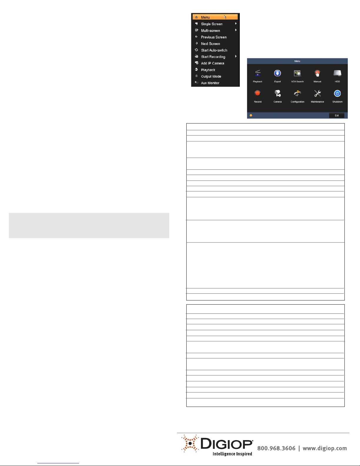
Step 7. Access the Menu System
Aer the initial setup of your Encoder using the Wizard, the Menus
interface enables you to rene your conguration settings and expand
the functionality of the system. To use most menus, the user must log
into the rmware system, either locally or remotely, with administrative
privileges. To open the Menu system from the Live View screen, right
click anywhere in the screen, then click Menu.
If ID Authentication is not disabled (see the
Menu | Conguration | General settings), a
login window will open. In the Login
window, select a User Name with administrative privileges, enter its password, then
Click OK. A window of Menu icons will open.
Specications
Model Encoder-HD16
Video compression H.265+/H.265/H.264 OVC/H.264
Video input 16-ch
BNC interface (1.0 Vp-p, 75Ω), supporting coaxitron
connection
Supported HD-TVI input 2 MP (channels 1, 2, 3, 4 only), 1080p30,
720p60, 720p30
AHD input 1080p30, 720p30
HD-CVI input 1080p30, 720p30
Audio compression G.711u
Audio input 1-ch, RCA (2.0 Vp-p, 1KΩ)
CVBS output 1 channel, (1.0 Vp-p, 75Ω), resolution 704x480
HDMI / VGA output VGA: 1-ch, 1920 x 1080/60 Hz, 1280 x 1024/60 Hz,
1280 x 720/60 H, 1024 x 768/60 Hz.
HDMI: 1-ch, 4k (3840 x 2160)/30 Hz, 2k (2560 x 1440)/60 Hz,
1920 x 1080/60 Hz, 1280 x 1024/60 Hz, 1024 x 76860 Hz
Encoding resolution When 1080 Lite mode not enabled: 2MP /1080p/720p /
VGA /WD1 /4CIF/ CIF;
When 1080p Lite mode enabled: 2MP/ 1080p lite/720p lite,
VGA/WD1, 4CIF/ CIF
Frame rate Mainstream when 1080p Lite mode not enabled: for 2MP
stream access: 2MP / 1080/720p / VGA/ WD1 / 4CIF / CIF;
For 1080p stream access: 1080p/720p @15 fps;
VGA / WD1 / 4CIF / CIF @ 30 fps
For 720p stream access: 720p / VGA / WD1 / 4CIF / CIF
@ 30 fps
When 1080p Lite mode enabled: 2MP @ 15 fps, 1080p lite/
720p lite VGA / WD1 / 4CIF / CIF @ 30 fps
Video bit rate 32 Kbps to 6 Mbps
Audio output 1-ch, RCA (linear, 1KΩ)
Model Encoder-HD16
Audio bit rate 64 Kbps
Dual Stream Support
Stream type Video, Video & Audio
Synchronous playback 16- channel
Remote connections 128
Network protocols TCIP/IP, PPPoE, DHCP, DNS, DDNS, NTP, SADP, UPnP, HTTPS,
ONVIF
Network interface 1 x RJ45 10M/100M/1000M self-adaptive Ethernet interface
USB interface Front panel: 1 x USB 2.0
Rear panel: 1 x USB 3.0
Serial interface RS-485 (half-duplex)
Power supply 12 Vdc
Consumption ≤ 25 W
Working temperature +14° F ~ + 131° F (-10° C to +55° C)
Working humidity 10% to 90%
Dimensions (w x d x h) 15 x 12.6 x 1.9 inch (380 x 320 x 48 cm)
Contact DIGIOP for sales and support needs:
 Loading...