


DIGIOP® V8.7 NVR and Hybrid DVR
Systems Setup Guide
Products: AH Series, DH Series, DM Series, EH Series, PH Series Hybrid DVRs
AI Series, DI Series, EI Series NVRs
PLEASE READ THIS MANUAL BEFORE USING YOUR SYSTEM, and always follow the
instructions for safety and proper use. Save this manual for future reference.
DO_V8.7_NVR-hDVR_SI
9/20/13

ii
www.digiop.com
Revision History
Date Reason for Change
5/12/12 Initial release.
11/5/12 Supports DIGIOP ELEMENTS™ V8.5 systems.
1/18/13 Includes R210 chassis hardware troubleshooting guidelines.
5/14/13 Supports DIGIOP ELEMENTS™ V8.6 systems.
5/22/13 Includes DIGIOP ELEMENTS™ systems pre-congured with the SV4000 Storage Vault. Includes GoMobile usage.
9/16/13 Includes DIGIOP DH, DI, DM serie s hardware chas sis
CAUTION
Operate this system only in environments where the temperature and humidity are within the recommended range.
Operation in temperatures or at humidity levels outside the recommended range may cause electric shock and shorten the
life of the product. Refer to the specications for each system component for more information.
LEGAL NOTICE
DIGIOP® products are designed to meet safety and performance standards with the use of specic DIGIOP®
authorized accessories. DIGIOP® disclaims liability associated with the use of non-DIGIOP® authorized accessories.
The recording, transmission, or broadcast of any person’s voice without their consent or a court order is strictly
prohibited by law.
DIGIOP® makes no representations concerning the legality of certain product applications such as the making,
transmission, or recording of video and/or audio signals of others without their knowledge and/or consent. We
encourage you to check and comply with all applicable local, state, and federal laws and regulations before
engaging in any form of surveillance or any transmission of radio frequencies.
Microsoft, Windows, and Internet Explorer are either registered trademarks or trademarks of Microsoft Corporation
in the United States and/or other countries. Dell, OptiPlex and PowerEdge are either registered trademarks or
unregistered trade marks of Dell Inc in the United States and other countries.
Other trademarks and trade names may be used in this document to refer to either the entities claiming the marks
and names or their products. DIGIOP, Inc. disclaims any proprietary interest in trademarks and trade names other
than its own.
No part of this document may be reproduced or distributed in any form or by any means without the express written
permission of DIGIOP, Inc.
© 2013 DIGIOP, Inc. All Rights Reserved.
9340 Priority Way West Drive, Indianapolis, IN 46240
For Sales and Support, please contact your distributor.

iii
NVR and hDVR Systems Setup Guide
Table of Contents
SECTION 1 Systems Overview ................................................................... 1
SECTION 2 Getting Started: Unpacking Your System ...............................................3
2.1 Unpacking the equipment .............................................................3
2.2 System installation tips ...............................................................3
SECTION 3 System Setup ....................................................................... 6
3.1 Check LAN for default IP address compatibility ...........................................7
3.2 Determine the network settings for each IP device ........................................8
3.3 Install and connect the IP camera/encoder to the LAN .....................................9
3.4 Repeat for all IP cameras ..............................................................9
3.5 Install the NVR or hDVR hardware ......................................................9
3.5.1 Install and setup the monitor ......................................................9
3.6 Install analog cameras (hDVR systems only) ..............................................9
3.7 Connect analog cameras, I/O sensors and alarms to hDVR .................................10
3.7.1 Make I/O connections ...........................................................19
3.7.2 For new DIGIOP® servers pre-congured with the SV4000 Storage Vault ................19
3.8 Congure NVR/hDVR clock and network settings ........................................19
3.9 Add cameras to the NVR/hDVR ........................................................20
3.9.1 Login to DIGIOP® Control .........................................................21
3.9.2 DIGIOP VIDEO SERVER - Edit Settings ...............................................22
3.9.3 hDVRs only - congure hDVR capture board ........................................23
3.9.4 hDVRs only - Add analog cameras ................................................25
3.9.5 Add a “Discovered” IP cameras to the NVR/hDVR .....................................27
3.9.6 Add an IP camera not “Discovered” ................................................30
3.10 Edit camera settings .................................................................33
3.11 Recorder Events .....................................................................34
3.11.1 Trigger recording on sensor input (hDVRs only) ......................................34
3.12 Congure system notications ........................................................35
3.13 DIGIOP DATA SERVER - Edit Settings ....................................................36
3.13.1 Add data devices ...............................................................37
3.14 Viewing video from your cameras with DIGIOP® Connect ..................................38
3.14.1 Install DIGIOP® Connect .........................................................38
3.14.2 Login to DIGIOP ELEMENTS™ through DIGIOP® Connect ...............................39
3.14.3 Logout of DIGIOP® Connect ......................................................41
3.15 Using the GoMobile smartphone app ..................................................42
APPENDIX A FAQ ..............................................................................44
APPENDIX B Server Hardware Troubleshooting ....................................................45

iv
www.digiop.com
B.1 Dell Optiplex® XE hardware common error indications ....................................45
B.2 Dell Optiplex 790, Optiplex 990 hardware common error indications ........................48
B.3 Dell Optiplex 7010/9010 common error indications ......................................54
B.4 Dell PowerEdge® R210 chassis troubleshooting ..........................................59
APPENDIX C System Troubleshooting ............................................................70
C.1 Unit does not power up ..............................................................70
C.2 Troubleshooting Questions/Suggestions ................................................70
C.3 Auto Reboot occurs when the Server is running ..........................................70
C.4 Auto Reboot occurs before the Server launches ..........................................71
C.5 Unit powers on then shuts o .........................................................71
APPENDIX D Troubleshooting DIGIOP® and BLACK Brand (The Black Line) IP Cameras ....................72
D.1 IP Camera reset .....................................................................72
D.2 Set camera to factory default network settings ..........................................72
D.2.1 Checking your rmware .........................................................73
D.3 Support ...........................................................................73
APPENDIX E Conguring the DIGIOP® and Black Brand (The Black Line) IP Camera Address ...............74
E.1 Install IPAdmin Tool .................................................................74
E.2 Congure the camera network settings .................................................74
E.3 Conguring the camera network settings ...............................................75
E.4 Connect to the camera with IE ........................................................76
APPENDIX F TCP/IP Port Settings and the Firewall .................................................78
APPENDIX G Power over Ethernet ................................................................79
G.1 PoE compatibility ...................................................................79
G.2 Power classication .................................................................79
APPENDIX H Device Log ........................................................................80

1
NVR and hDVR Systems Setup Guide
SECTION 1: SYSTEM OVERVIEW
SECTION 1
Systems Overview
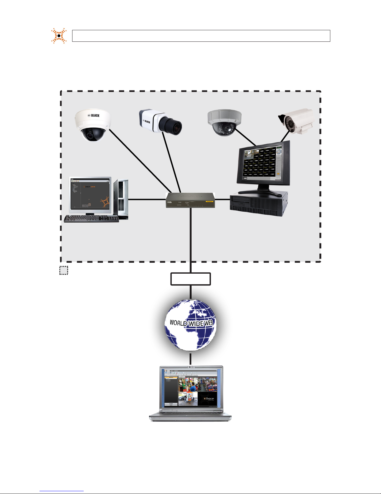
DIGIOP®Network Video Recorder (NVR) and Hybrid Digital Video Recorder (hDVR) servers with the DIGIOP ELEMENTS™ video and
data management software feature state-of-the-art management for advanced analog and IP cameras with real-time data capture.
DIGIOP ELEMENTS™ is a seamless suite of video and data intelligence products includes that combine raw video with information
from back-oce systems with video analytics. It includes four components:
• DIGIOP® Connect - DIGIOP® Connect is a remote client that displays both video and data from multiple sources together
in a unied easy-to-use dashboard. The software can be used to view live and recorded video, locally or across a LAN or the
Internet.
• DIGIOP® Control - DIGIOP® Control is a web-based administration portal that enables you to congure your systems and
manage permissions from anywhere you have Internet access. It allows you to manage your video, data, and user information
across your single- or multi-site system. Controls include: add and congure cameras, set user rights, establish global and local
level permissions for systems, cameras, and data streams. DIGIOP® Control also allows you to create groups and auto tours by
customizing your dashboard to improve real time store visibility and performance.
• DIGIOP® Core - An extensible video recording platform that provides real-time recording of analog and IP cameras. DIGIOP®
Core manages, records, and stores digital video and images, and controls camera PTZ. It also includes several surveillance
management features including system security and activity logging. Core software can be congured to display live video as
it’s recorded, or to run in the background and archive video data for display using DIGIOP® Connect.
• DIGIOP® Data - A data management software that integrates external data with video recorded by DIGIOP® Core. This
information can be displayed and retrieved with DIGIOP® Connect. DIGIOP® Data integrates video with retail Point-of-Sale
(POS), to school Time & Attendance, to healthcare Electronic Access Control (EAC), etc. to expand the potential of your system.
There is no direct user interface to congure or control DIGIOP® Data.
In NVRs and hDVRs, analog cameras are added to the system and assigned to video channels by the video connector they
are attached to. IP cameras are added to the system through the DIGIOP® Control interface, a web-based conguration and
management feature of the system.
All DIGIOP® IP cameras and encoders include an IPAdmin Tool, a Microsoft Windows-based application for conguring network
settings and rmware updates. Depending on your NVR or hDVR, IPAdmin Tool may be pre-installed.
Local and Hosted-Enterprise Management
The DIGIOP ELEMENTS™ server can be managed either locally or by DIGIOP®. With a locally managed NVR or hDVR server, the
conguration settings are retained on the server. In a hosted enterprise environment, DIGIOP® manages the servers and saves the
server conguration settings at DIGIOP®. For hosted enterprise management, the NVR and hDVR servers must be accessible through
2
www.digiop.com
SECTION 1: SYSTEM OVERVIEW
the Internet. The selection of using either local or hosted enterprise management is made through the Enterprise Conguration
Application in the Windows Start menu.
IP Cameras
DIGIOP® Connect
DIGIOP® Control (remote access)
Router
Modem
Analog Cameras
DIGIOP® Core Video & Data Servers
DIGIOP® Control
NVR (IP and Data Devices) or
hDVR (IP, Analog and Data Devices)
= Local System
IPAdmin Tool
DIGIOP® Connect
DIGIOP® Control (remote access)

3
NVR and hDVR Systems Setup Guide
SECTION 2: GETTING STARTED: UNPACKING YOUR SYSTEM
SECTION 2
Getting Started: Unpacking Your System
For most installations, DIGIOP® NVR and hDVR systems come with everything needed to install and operate your system.
2.1 Unpacking the equipment
Remove the equipment from its packaging and place it on a at, clean surface. Inspect each item. If any visible damage is present,
contact your supplier for a replacement. Verify that your order is complete. Within your order you should nd:
• The number of cameras you ordered. Each IP camera includes a power supply, a software CD, and a Quick Installation Guide.
Depending on your camera model, other items may be included.
• NVR or hDVR server including:
— Mouse (standard USB)
— Keyboard
— Video input cable(s)
— Power cord
— PTZ control cable (on some systems)
— PTZ RS-232 cable (on some systems)
— Recovery DVD
— Application disk
— Hardware Quick Start Guide, Software Quick Start Guides
— Surge protection and anti-virus warning document
• Accessories you ordered
Refer to the user manual for the product for a list of specic items included with the product. The user manual may be provided on
the CD included with the product.
NOTE
Large systems may be shipped in several cartons.
2.2 System installation tips
Camera placement
Use the information included in the packaging of your camera to mount and connect the unit to power and video cable(s). Plan your
camera installation carefully. Identify the locations where cameras will provide the best coverage, considering:
• Field of view – Cameras must be positioned so they can eectively view the entire area that must be monitored.
• Lighting – Is there enough light in the eld for the camera to “see” clearly? Is there intense light from the sun or shiny objects
that reect onto the camera lens? These conditions may aect the video quality and camera performance.
4
www.digiop.com
• Ease of installation – Must be able to install the camera at the location, considering mounting hardware requirements,
temperature, dust, moisture, etc.
DIGIOP® recommends that you bench test all cameras and cables before installing them.
Weatherproof cameras
Weatherproof cameras can be mounted in any open area, such as on a telephone pole or on the side of a building. However, for best
results, we recommend you mount your cameras in a sheltered area, such as under the eave or roof of a building. Point the camera
in the direction you wish to observe. When routing cable near the camera, allow enough slack to form a “U” shaped drop to help
direct moisture, that accumulates on the cable, away from the camera.
NOTE
Cable connections are not weatherproof.
Cable runs
LAN/power cables can be run almost anywhere, and are frequently routed above drop/acoustic ceilings because of the ease of
installation. For added security, we recommend you run your cables in areas with limited access to prevent tampering. Avoid
running the cable near high voltage appliances such as uorescent lighting. Electrical noise and magnetic elds produced by these
devices may aect video signal quality.
NVR/hDVR placement
Your monitoring and recording equipment is central to the accurate capture of video evidence and constant surveillance. DIGIOP®
strongly suggests that it be installed in a secure location with access limited to authorized personnel. Additionally, NVRs and
hDVRs generate heat and should be placed in a well ventilated area. Excessive heat will reduce the life span and reliability of the
equipment.
The monitor does NOT need to be on for recording to occur. NVRs and hDVRs will output and record video regardless of the
operational status of the monitor as congured.
Uninterruptible power supplies
It is strongly suggested that power to the system be routed through an uninterruptible power supply (UPS). These devices will keep
your security system running through most power outages, in addition to providing excellent voltage surge and drop protection.
The UPS should support your video recorder and all cameras to ensure operation during power outages.
WARNING
!
Be sure to following all CAUTIONS and WARNINGS found with the system. Failure to do so may result in injury or
damage to the equipment.
SECTION 2: GETTING STARTED: UNPACKING YOUR SYSTEM

5
NVR and hDVR Systems Setup Guide
SECTION 2: GETTING STARTED: UNPACKING YOUR SYSTEM
Notes:
• IP devices – systems are compatible with many IP devices such as DIGIOP® and Observint Technologies BLACK and The
BLACK Line cameras and encoders, and many AXIS® , Sony®, Arecont®, Canon®, IQEye®, ACTi® , LG®, 3S and other manufacturer’s
cameras and encoders.
• NTSC or PAL – systems are compatible with NTSC or PAL, respectively, analog cameras.
• Ground loops and power uctuations – To ensure high-quality image capture and to prevent issues, check the system
for ground loops and power uctuations across the whole system.
• Low-light adjustments – Adjust the lighting, focus, or iris of the camera properly to avoid unnecessary motion detection in
low-light conditions.
• PTZ – systems do not support PTZ data signals or power on the video coax cables. Run separate cables to accommodate
system needs.
• Audio – All units come with at least one channel of audio; some come with multiple channels.
• Voice recording – Plug the microphone for voice recording into the microphone input jack. When the audio signal is line
level, then connect to the line-in jack. Connect the speaker to replay the recorded audio. The output signal is line level and
requires an amplier to boost the output signal for a speaker.
• Sensor inputs – These are activated by dry contact devices (the contact of a relay that does not make or break a current;
usually some other relay or device starts or stops the current) and are not “balanced.” Inputs connect to either N/O (normally
open) or N/C (normally closed) sensor contacts. Each input is congured in the software, depending on the input type. To
conrm correct operation, close the sensor device for at least 0.5 seconds.
• Sensor outputs – These can be activated automatically with DIGIOP® Control, or manually with DIGIOP® Connect.
• Relays – When using the Relay outputs, ensure that the voltage/current capacity of the relays is not exceeded.
• Network Connections – The Network settings are used to congure your system for DIGIOP® Control, DIGIOP® Connect,
and DIGIOP ELEMENTS™ accounts.
• IP devices – When using IP devices, to ensure that adequate bandwidth is available for system operations and video
transmission, set up a separate or segregated network. See the IP device manufacturer’s recommendations for bandwidth
requirements.
• Printers – If you are using a printer, make sure to use a good quality, color printer and appropriate paper to achieve optimal
results.
6
www.digiop.com
SECTION 3: SYSTEM SETUP
SECTION 3
System Setup
Your DIGIOP® NVR/hDVR system includes the computer with the DIGIOPELEMENTS™ software and the analog and IP cameras and
encoders that you added to it. The NVR or hDVR and IP cameras and encoders are usually congured with xed (static) IP addresses
on the same subnet. Analog cameras are connected directly to the computer through integrated video and audio capture hardware,
or can be connected across the LAN through an IP encoder.
Each camera and encoder model has specic installation and usage instructions. Review these instructions carefully when planning
the setup of your system. Since many systems include the high-performance DIGIOP® cameras, extra consideration is included
herein to aid their installation and setup.
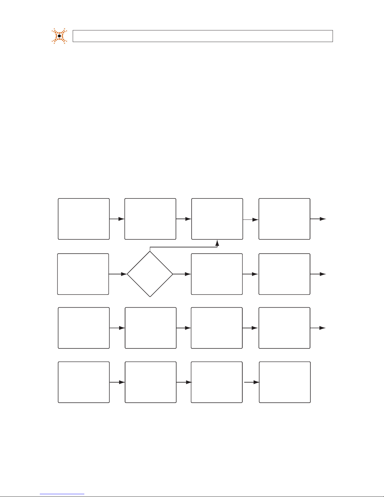
The general procedure for installing and setting up your system is shown in the following ow chart.
Check network for
compatibility with
default IP addresses.
Section 3.1
Determine the
network settings for
all IP devices.
Section 3.2
Install IP camera or
encoder:
- Connect audio, etc.
- Connect network cable
- Connect power
Section 3.3
Congure camera/
encoder network
settings.
Section 3.3
Setup the camera
conguration:
- Video settings
- Setup motion
detection.
- Etc.
Section 3.3
Install another
IP camera?
Section 3.4
Yes
No
Install NVR/hDVR
hardware.
- Install and setup
a monitor
Sections 3.5
Install analog cameras
in their surveillance
locations:
- Route power, video
audio cables to
hDVR
Sections 3.6
Connect analog
cameras to the hDVR:
- Connect video and
audio cables
- Connect sensors and
alarms
Section 3.7
Congure the NVR/hDVR
clock and network
settings
Sections 3.8
Congure DIGIOP VIDEO
SERVER
Sections 3.9
Add (analog/IP) cameras
to the NVR/hDVR
- Name camera channel
- Add IP cameras not
discovered
- Edit camera settings
Sections 3.9
Congure DIGIOP DATA
SERVER
- Add data devices
Sections 3.13
Edit Camera Settings,
Setup record triggering.
Sections 3.10, 3.11
Install DIGIOP™ Connect
software.
- Link to an NVR/hDVR.
- Add video or data
servers
- Logout of Connect
Sections 3.14
Congure system
Notications
Sections 3.12
General Installation and Setup Flowchart
7
NVR and hDVR Systems Setup Guide
SECTION 3: SYSTEM SETUP
3.1 Check LAN for default IP address compatibility
All IP devices (computers, cameras, encoders, etc.) are initially setup with factory default network settings. Some devices are
preset with xed (static) IP address, while others acquire their network settings through a DHCP server. For instance, all DIGIOP® IP
cameras and encoders are factory congured to acquire an IP address from a DHCP server, if one is present, or default to the factory
preset IP address 192.168.0.100. To avoid addressing conicts on networks without DHCP, perform the following steps to check the
network before connecting your camera to ensure that network conicts won’t occur. On networks with DHCP, skip to section 3.2.
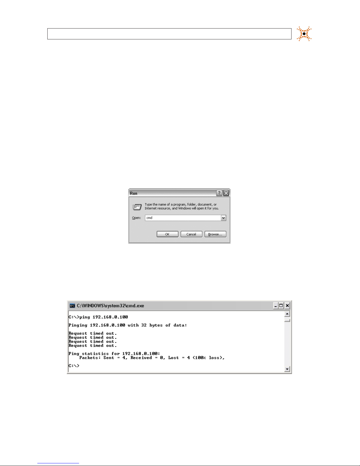
1. At a Microsoft Windows computer attached to the LAN subnet where the camera will be connected (surveillance network),
open a Command Prompt window.
a. Click the Windows Start button. If using Windows XP, select Run.
b. In the “Search..” eld (Windows Vista or Windows 7), or Open eld (Windows XP), enter “cmd”, then click OK.
2. At the command prompt, use the ping command to see if the default IP address of your IP device is in use. If the default
static IP address is 192.168.0.100, enter:
ping 192.16 8.0.100
The “Request timed out” response indicates that the IP address is not currently in use and the camera can probably be
connected without causing conicts.
8
www.digiop.com
SECTION 3: SYSTEM SETUP
A “Reply from ..” message received from a ping indicates that an active device with that IP address exists on the network,
and new devices with that address shouldn’t be attached to that network without rst changing the network settings of the
device. Use the manufacturer’s recommended procedure for changing the address before attaching it to the LAN.
NOTE
For DIGIOP® cameras and encoders
To change the IP address before connecting it to the surveillance LAN:
- Determine the new IP address for the device using the procedure outlined in section 3.2 below.
- Setup the device temporarily on a LAN where 192.168.0.100 is not in use and power it on.
- Install the IPAdmin Tool on a computer on the LAN where the device is temporarily located (see Section 3.3)
- Use the IPAdmin Tool to setup the new IP address, subnet mask, and gateway for the device (see Section 3.5 below)
- Power o the device and disconnect it from the LAN where it was temporarily setup. It will retain the new network settings you
congured it with.
3. Use the ping command to verify that the static IP addresses of other devices in your surveillance system won’t conict with
devices already installed on the network.
3.2 Determine the network settings for each IP device
Consult with your LAN network administrator to obtain a list of network settings for each IP device, including the NVR or hDVR
and all cameras and encoders, you will attach to your LAN. You must use a static IP address for your surveillance system to ensure
connectability with the NVR or hDVR. The IP Device Summary table in Appendix E may be useful for logging your network settings.
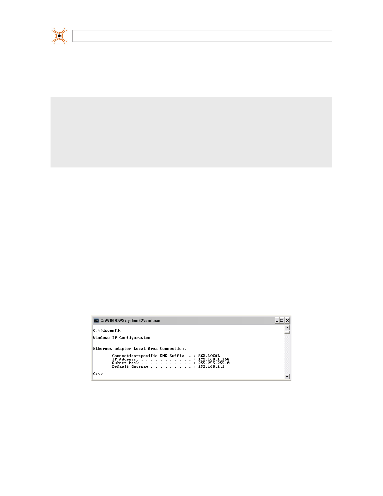
To determine (or verify) which IP addresses are available on your surveillance network, use the ping command as described in
section 3.1 to test each address. Also, determine the subnet mask, gateway, and the DNS address (if used). The subnet mask and
gateway may be the same as the computer you use to access the network, and can be found with the ipcong command in the
command prompt window.
Example: Typical use of ipcong in Windows XP
When an adequate number of unassigned IP addresses is determined, continue with the next section.

9
NVR and hDVR Systems Setup Guide
SECTION 3: SYSTEM SETUP
3.3 Install and connect the IP camera/encoder to the LAN
1. Use the Device Log (see Appendix G) to record the description, MAC address, network settings (IP address, subnet mask,
gateway, and DNS server address), and the location to assign to each camera.
2. Bench test the camera or install it in the surveillance location in accordance with the manufactures suggested procedure.
NOTE
If your camera will be powered with a PoE switch, use this switch in the power/LAN connection to verify the functionality of the
switch. Refer to “APPENDIX G
Power over Ethernet” on page 79 for more information about PoE powering and your camera.
3. Connect your IP camera to the LAN. Use the manufacturer’s suggested procedure to congure its network settings. For
DIGIOP® cameras and encoders, see Appendix D.
4. Adjust the camera video settings, setup the motion detection conguration, time and time zone, etc. if necessary.
5. Verify connectability to the device using network based software as suggested by the manufacturer. For DIGIOP® cameras
and encoders, see Appendix D.
3.4 Repeat for all IP cameras
Repeat step 3.3 for each camera or encoder you install. Setup one camera at a time to prevent network conicts between cameras
that have the same initial IP address.
3.5 Install the NVR or hDVR hardware
Install your NVR or hDVR hardware. Refer to the Quick Start Guide included with the equipment. Do not power on the NVR/hDVR at
this time.
3.5.1 Install and setup the monitor
Install and setup your monitor in accordance with the instructions provided with it. Connect the monitor to your NVR or hDVR at this
time, but do not power it on.
3.6 Install analog cameras (hDVR systems only)
Refer to section “2.2 System installation tips” on page 3 for useful information about installing cameras. If you are installing an hDVR
system with analog cameras, do the following:
10
www.digiop.com
SECTION 3: SYSTEM SETUP
1. Install and setup all analog cameras in their surveillance locations in accordance with the manufacture’s suggested
procedures.
2. Route the video/audio/power extension cable from each camera to the location where the hDVR is installed.
NOTE
Typically, the power connectors on video extension cables are dierent at each end. When routing these cables, ensure that the
connectors match the devices they attach to.
3.7 Connect analog cameras, I/O sensors and alarms to
hDVR
Analog cameras are assigned to camera channels in the DIGIOPCore software by attaching them to the video connector associated
with the channel. Similarly, audio sources are associated with camera channels by attaching them to the audio connector associated
with the camera channel.
NOTE
If you purchased a DIGIOP® server pre-congured with an SV4000 Storage Vault, an expansion card slot will include an STR-CTRL
controller card. The expansion card arrangement will be dierent from that shown below for your server.
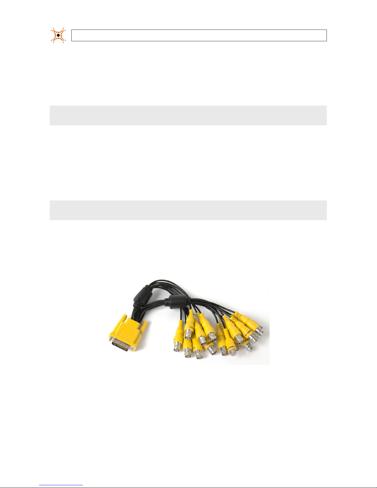
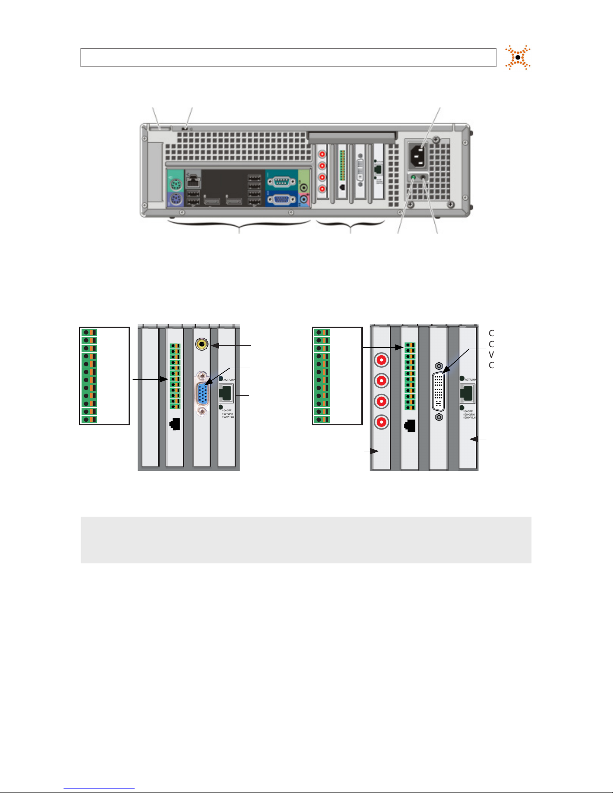
3. Connect the video adapter cable(s) provided with your system to the video capture card in the expansion slot of the
computer. The video capture card in some computers accommodate a single 16-channel adapter with BNC and a DVI-style
connector, another type provides an 8-channel adapter with BNC and a VGA style connector. Notice that all BNC connectors
are labeled for the channel number assigned to the connector. (See the images below for your system.)
Typical 16-channel video adapter cable (with DVI style connector)
11
NVR and hDVR Systems Setup Guide
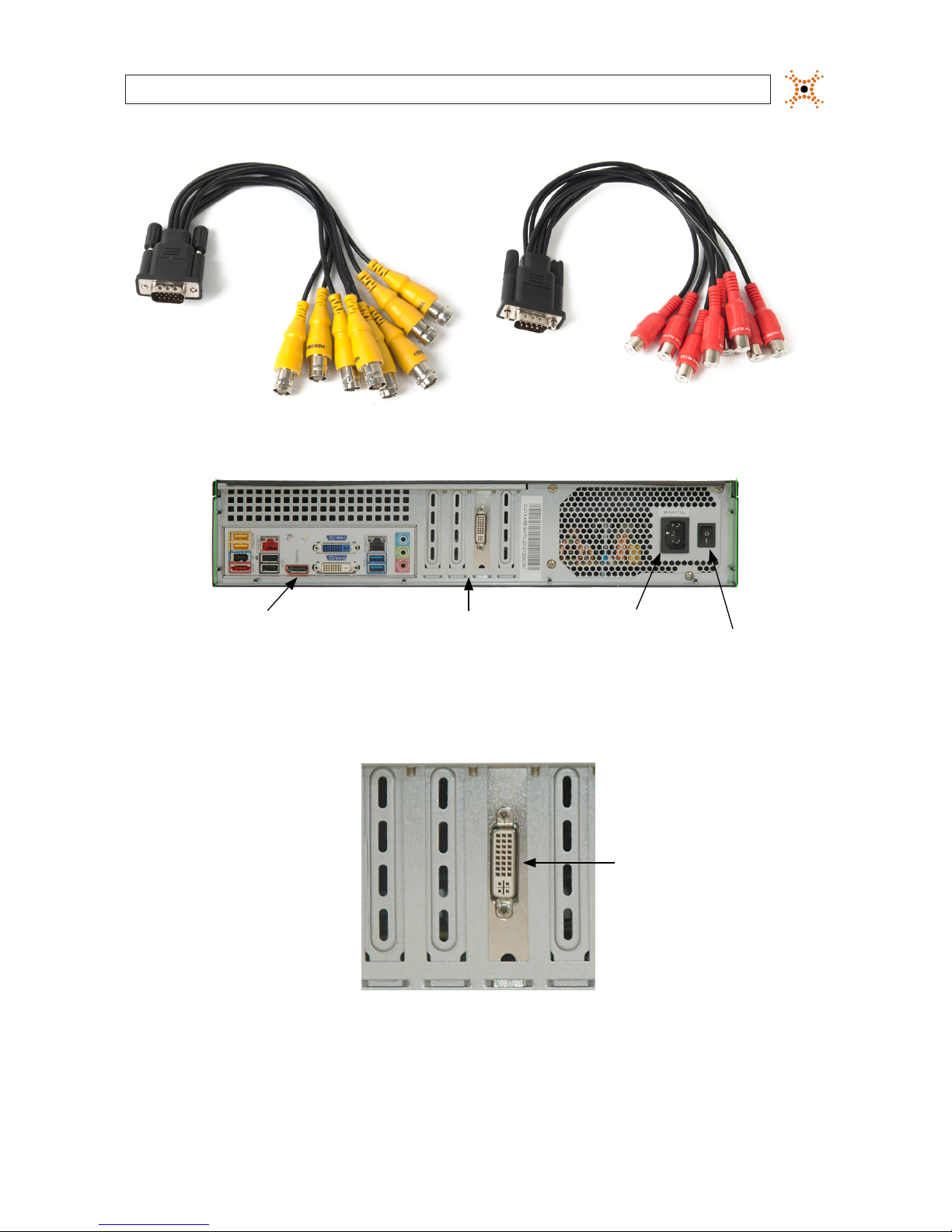
Typical 8-channel video cable adapter Typical 8-channel audio cable adapter
Power On / O switch
Back panel
Power cable connector
Expansion cards
FlexVR™ 2U backpanel (DM series systems)
The FlexVR 2U chassis DI series systems has no expansion cards.
Video In
DVI connector
for video adapter
dongle
DM16 series expansion cards
SECTION 3: SYSTEM SETUP
12
www.digiop.com
SECTION 3: SYSTEM SETUP
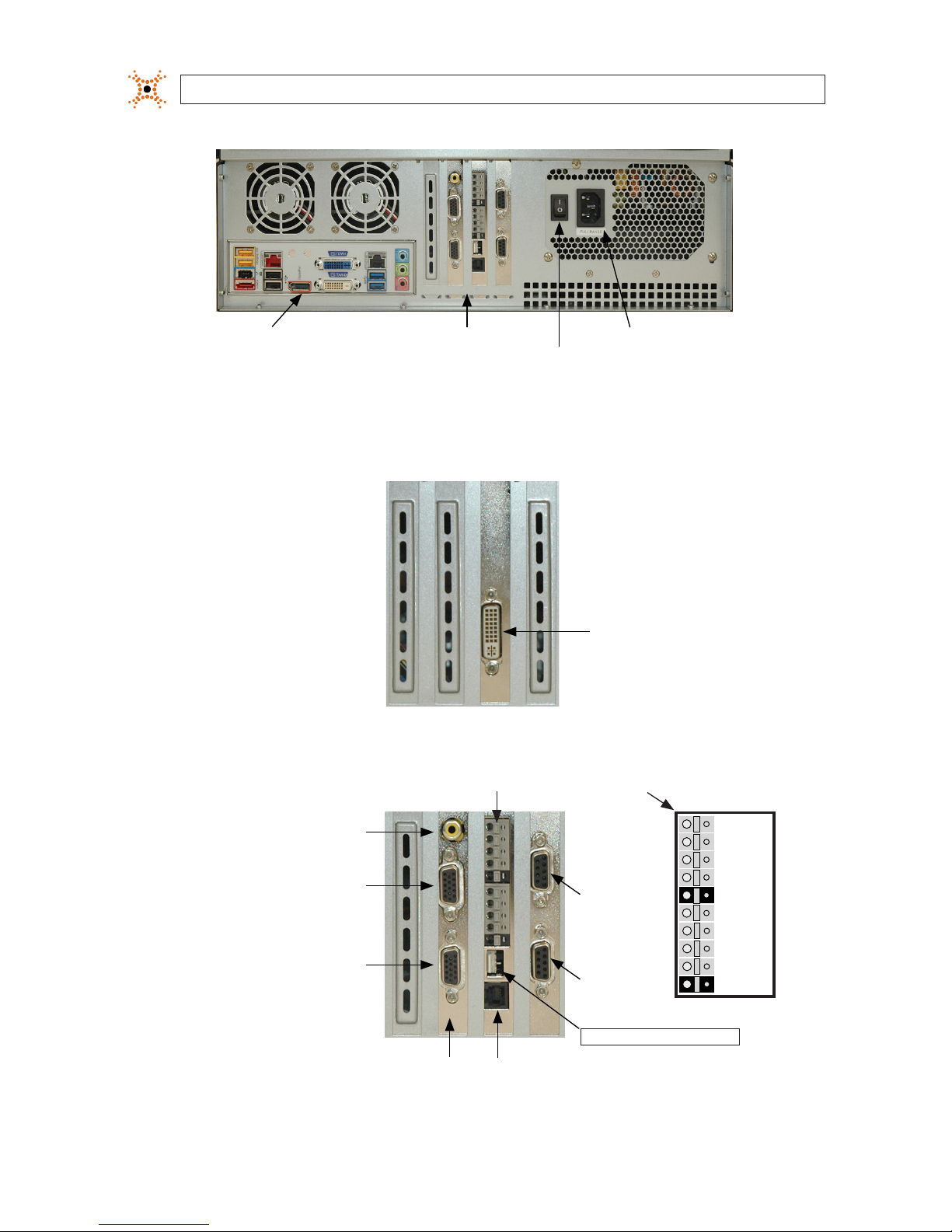
Power On / O switch
Back panel Power cable connectorExpansion cards
FlexVR™ 3U backpanel (DH, DM sseries systems
The FlexVR 3U chassis DI series systems have no expansion cards.
Video capture card:
Ch 1 - 16 in,
Spot out 1, 2
DM16 series expansion cards
Video capture card
Ch 1 - 8 in
Ch 9 - 16 in
Audio
Ch 9 - 16 in
Audio
Ch 1 - 8 in
RS485: TX+, TX–, RX+, RX–
Spot out
(Ch 1 - 16)
Sensors and Control Terminals
Control 1
Sensor 1
Sensor 2
Sensor 3
Sensor 4
Control 2
Control 3
Ground
Ground
Control 4
DH16 series expansion cards
13
NVR and hDVR Systems Setup Guide
SECTION 3: SYSTEM SETUP
Video capture cards
Ch 17 - 24 in
Ch 25 - 32 in
Ch 1 - 8 in
Ch 9 - 16 in
Audio
Ch 9 - 16 in
Audio
Ch 1 - 8 in
Spot out
(Ch 1 - 16)
Spot out
(Ch 25 - 32)
Sensors and Control Terminals
Control 1
Sensor 1
Sensor 2
Sensor 3
Sensor 4
Control 2
Control 3
Ground
Ground
Control 4
RS485: TX+, TX–, RX+, RX–
DH32 series expansion cards
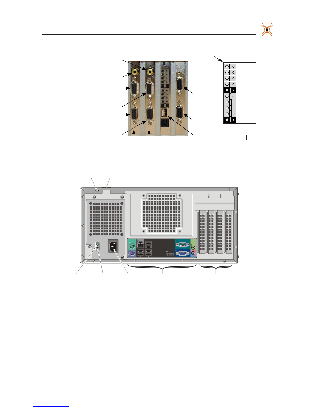
Power Supply
Diagnostic
Light
Power Supply
Diagnostic
Button
Security Cable Slot
Back Panel
Connectors
Expansion
Card Slots
Padlock Ring
Power
Connector
OptiPlex 990 backpanel (AI50, AH, PH series systems)
14
www.digiop.com
SECTION 3: SYSTEM SETUP
Sensors and Control Terminals
Network
card
Video In
CH17 - CH32
Audio In CH9 - CH16
Video In
CH1 - CH16
Audio In CH1 - CH8
TX+
TX–
RX+
RX–
RS485
Terminals:
Control 1
Sensor 1
Sensor 2
Sensor 3
Sensor 4
Control 2
Control 3
Ground
Ground
Control 4
OptiPlex 990 expansion slots (AH series systems)
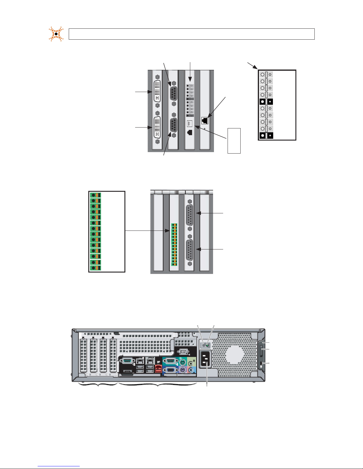
Video In
CH9 - CH16
Audio In
CH3 - CH4
(PH only)
Video In
CH1 - CH8
Audio In
CH1 - CH2
(PH only)
Sensor 1
Ground
Sensor 2
Ground
Sensor 3
Ground
Ground
Sensor 4
Relay 2
Ground
RS485 TRX +
RS485 TRX −
Ground
Relay 1
Optiplex 990 expansion slots (PH series systems)
The OptiPlex 990 chassis AI series system hardware has no expansion cards.
Power Status LEDPower Self-Test Button
Cover
Release
Latch
Security
Cable
Slot
Power Cable ConnectorBack Panel ConnectorsExpansion Slots
OptiPlex XE backpanel (EH30, EI30 series systems)
15
NVR and hDVR Systems Setup Guide
SECTION 3: SYSTEM SETUP
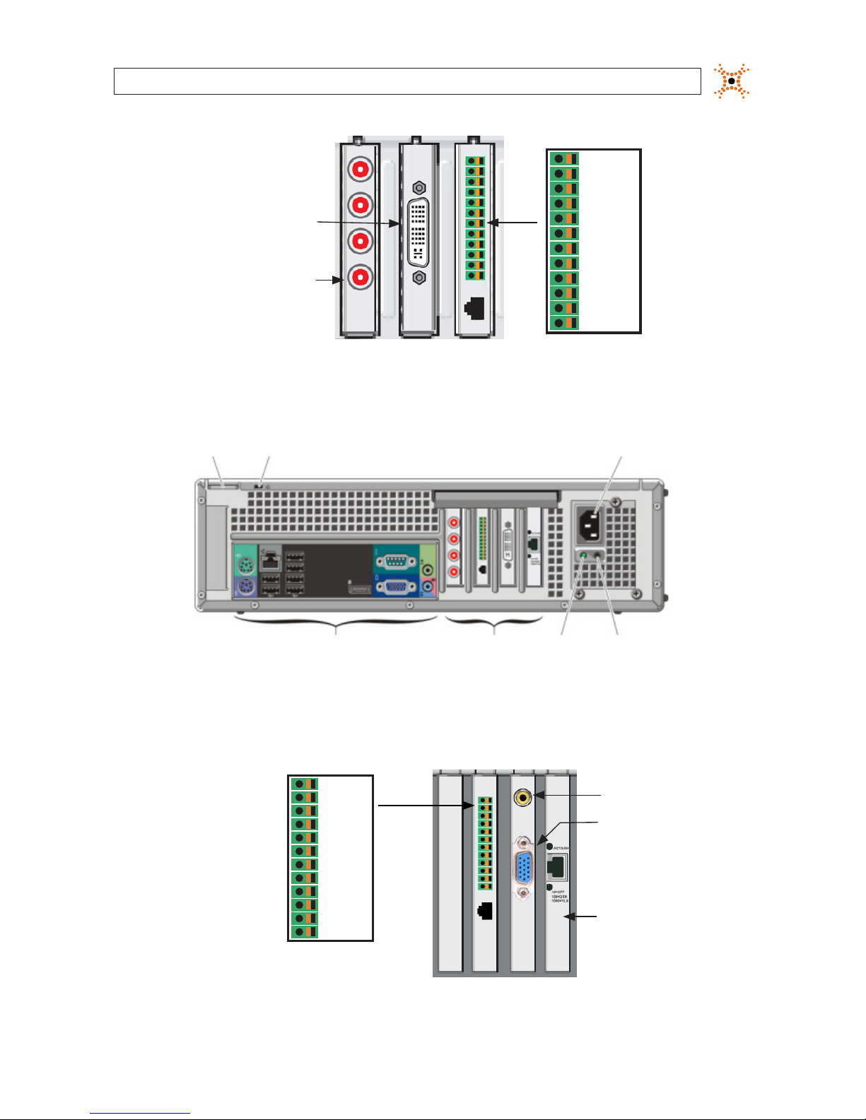
Audio Input
CH1 - CH4
(bottom to top)
(EH30 only)
Video In
DVI Connector
(EH only)
Output 1
Output 2
Ground
Input 1
Input 2
Ground
TRX +
TRX −
RX +
RX −
Input 3
Input 4
OptiPlex XE expansion slots (EH series systems)
The OptiPlex XE chassis EI series system has no expansion cards.
Diagnostic
LED
Power Supply
Diagnostic Button
Security Cable Slot
Padlock ring Power Cable Connector
Back Panel Connectors Expansion Slots
Optiplex 790 chassis backpanel (EH21 series systems)
The OptiPlex 790 chassis EI21 series system has no expansion cards.
Output 1
Output 2
Ground
Input 1
Input 2
Ground
TRX +
TRX −
RX +
RX −
Input 3
Input 4
Video In Connector
Network Interface
Card
Spot Out Connector
Optiplex 790 EH2104 expansion slots
16
www.digiop.com
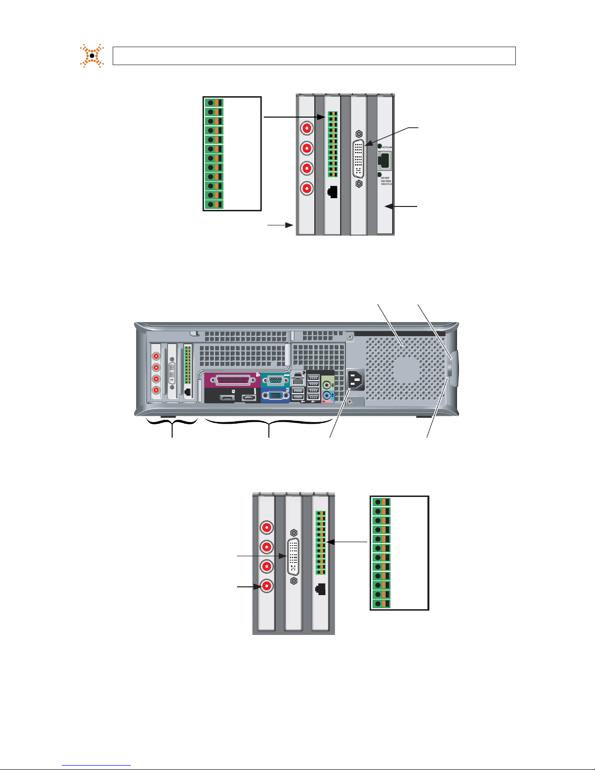
Output 1
Output 2
Ground
Input 1
Input 2
Ground
TRX +
TRX −
RX +
RX −
Input 3
Input 4
Video In
Connector
Audio Inputs
CH1 - CH4
(bottom to top)
Network
Interface
Card
Optiplex 790 EH2108, EH2116 expansion slots
Security Cable Slot
Padlock ring Cover Release Latch
Power Cable ConnectorBack Panel ConnectorsExpansion Slots
Optiplex 780 Chassis backpanel (EH20 series systems)
Output 1
Output 2
Ground
Input 1
Input 2
Ground
TRX +
TRX −
RX +
RX −
Input 3
Input 4
Video In
Connector
Audio Inputs
CH1 - CH4
(bottom to top)
Optiplex 780 EH2008, EH2016 expansion slots
SECTION 3: SYSTEM SETUP
17
NVR and hDVR Systems Setup Guide
SECTION 3: SYSTEM SETUP
Padlock ring Security Cable Slot Power Cable Connector
Back Panel Connectors Expansion Slots Diagnostic
Button
Diagnostic
Light
Optiplex 7010 chassis backpanel (EH22, EI22 series systems)
Capture
Card
Video In
Connector
Audio Inputs
CH1 - CH4
(bottom to
top)
Network
Interface
Card
Output 1
Output 2
Ground
Input 1
Input 2
Ground
TRX +
TRX −
RX +
RX −
Input 3
Input 4
Video In
Connector
Network
Interface
Card
Spot Out
Connector
Output 1
Output 2
Ground
Input 1
Input 2
Ground
TRX +
TRX −
RX +
RX −
Input 3
Input 4
EH2204 (left) and EH2208/EH2216 (right) expansion slots
NOTE
If your computer hardware includes a 4-channel audio PC card and you are installing a camera with audio, connect the camera
video input to channel 1, 2, 3, or 4.
Connectors on the 4-channel audio PC card are for channels 1 – 4, bottom to top.

18
www.digiop.com
SECTION 3: SYSTEM SETUP
Padlock ringSecurity Cable Slot
Power Cable
Connector
Back Panel Connectors Expansion SlotsDiagnostic
Button
Diagnostic
Light
Optiplex 9010 chassis backpanel (AH, AI series systems)
Sensors and Control Terminals
Network card
Video In
CH17 - CH32
Audio In CH9 - CH16
Video In
CH1 - CH16
Audio In CH1 - CH8
RS485
Terminals:
Control 1
Sensor 1
Sensor 2
Sensor 3
Sensor 4
Control 2
Control 3
Ground
Ground
Control 4
TX+
TX–
RX+
RX–
AH systems expansion slots
4. Connect the audio adapter cable(s) to the audio capture card of the monitoring console computer. The audio capture card
may have 4 inputs (numbered 1 – 4, bottom to top), or an audio adapter cable similar to the video adapter cable, but
includes RCA female connectors instead of a BNC connectors.
5. Connect the analog camera video cables to the video adapter cable. Note that the each connector is numbered for the
assigned camera channel in the DIGIOP® Digital Surveillance Monitoring System software.
6. If a camera has an associated audio channel, connect the camera audio input to the audio channel (on the audio adapter
cable or 4-channel PC card) marked with the same channel number the camera video cable is connected to. For instance, if

19
NVR and hDVR Systems Setup Guide
SECTION 3: SYSTEM SETUP
the camera video input is attached to the CH 4 connector on the video adapter cable, connect the associated audio input to
the CH 4 connector of the audio adapter cable.
3.7.1 Make I/O connections
Make connection to sensors (input), relays (output) and an RS485 trunk as needed (see connector diagrams above). When selecting
the wire size and color for these connections, follow local codes.
Sensor inputs can be congured in the DIGIOP®Control software to trigger recording of one or more cameras. Sensors and relays
can be normally open (NO) or normally closed (NC) type devices.
NOTE
Normally open (NO) sensors are “active” when the contacts are closed. Normally closed (NC) sensors are “active” when the sensor
contacts are open.
RS485 terminals (TX+/–, RX+/–) provide a 4-wire RS485 interface.
3.7.2 For new DIGIOP® servers pre-congured with the SV4000 Storage
Vault
If you purchased your with the SV4000 Storage Vault and it was pre-congured by DIGIOP, use the instructions provided with the
SV4000 to setup the hardware, connect SAS interface cable to the DIGIOP server STR-CTRL controller card, and power it on. No
additional software conguration of the server is required. Wait at least 30 seconds before powering on the DIGIOP server in the
steps below.
If you purchased an SV4000 that is not pre-congured with your DIGIOP server, follow the setup instructions in provided with the
SV4000, including installing the STR-CTRL controller, loading drivers in the DIGIOP server, and editing the DiSSFactory.ini le
appropriately.
3.8 Congure NVR/hDVR clock and network settings
Your NVR/hDVR server, buy default, is congured to acquire network settings from a DHCP server. Since DHCP congured devices
have changeable network settings, it is suggested that you congure your server with static settings to simplify connecting to it
from other computers. Only IPv4 is supported. If you prefer to retain the default DHCP setup, skip this procedure.
Within the initial system conguration, changing the NVR/hDVR network settings are performed using Windows 7 procedures (see
below).

20
www.digiop.com
SECTION 3: SYSTEM SETUP
WARNING
!
Before powering on your server, make sure the power sources are grounded. This helps prevent personal injury or
damage to the equipment.
1. Before connectin g the power, ensure that the power source cong uration switch on the ba ck of the computer (computer p ower
supply) is set correctly.
2. Make sure all cables are securel y attached.
1. Power on your NVR or hDVR and allow it to progress to the windows desktop display.
NVR/hDVR server desktop display
2. Click the clock and date entry in the lower-right corner (system tray) of the desktop. Click Change Date and time
settings.., then use the accepted Windows 7 system procedure to congure your server with the local time and time zone.
3. Use the accepted Windows 7 system procedure to congure the network settings of you NVR.
4. Skip to the next subsection of this manual.
3.9 Add cameras to the NVR/hDVR
IP cameras are added to the NVR/hDVR and congured through the DIGIOP® Control interface. The DIGIOP® Control interface can be
opened through a web browser either in the NVR or hDVR, across the local LAN were the NVR or hDVR is installed, or from a PC on
the Internet. To use advanced conguration features such as adding additional licenses, see the DIGIOP® Control V8.7 User Manual.
21
NVR and hDVR Systems Setup Guide
SECTION 3: SYSTEM SETUP
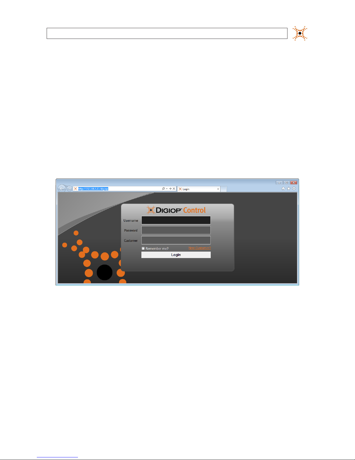
3.9.1 Login to DIGIOP® Control
1. To open DIGIOP® Control:
a. From the server desktop: Start the Microsoft® Internet Explorer® (IE) browser. The URL defaults to:
http://localhost/Digiop. You can also use the address http://127.0.0.1/digiop
b. From a computer on the LAN with the NVR/hDVR: DIGIOP® Control can be accessed from any computer with
Microsoft Internet Explorer across the LAN on the subnet where the DVR is networked. Open the browser and use the
URL: <IP Address>/digiop/digiop where IP Address can be the xed IP address of the DVR or the DNS address. In the
examples shown here, the IP address is 192.168.5.11, and is on the same subnet as the computer that is accessing it
from. The URL to use is: http://192.168.5.11/digiop
c. For DIGIOP® hosted servers: Open Microsoft Internet Explorer. Use the URL: elements.digiop.com
2. In the Welcome window, enter your assigned Username, Password, and Customer name. The default administrative
username/password for NVRs and hDVRs is admin/admin. For local login, the customer name should be digiop.
3. Click Login. After a successful login, the NVR/hDVR Home page will appear.
22
www.digiop.com
SECTION 3: SYSTEM SETUP
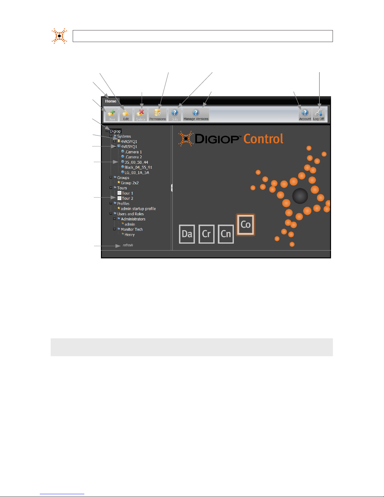
Manage Versions
(update software)
Account (change
User information)
NOTE: In this example, 4VR5YQ1 is the system hostname
Home Button
(return to here)
Object Tree
(Items
Congured
in System)
Data
Server
Customer
Name
Video
Server
Analog and
IP Cameras
Added to
the Video
Server
New Button
(to add objects
to the tree)
Refresh Button
(to update
object tree)
Edit Button (to change
object options)
Delete Button
(delete objects)
Info Button (displays software
version, status, license capabilities)
Secure/Permissions Button
(to set an object permission)
Log O
(exit)
3.9.2 DIGIOP VIDEO SERVER - Edit Settings
To open DIGIOP VIDEO SERVER the settings window, click the Video Sever icon in the object tree to highlight it, then click the Edit
button in the application header. The screen below shows the edit menu for a hDVR which includes additional setup links for the
video capture board and PTZ camera proles.
NOTE
Do not delete the Video Server or Data Server in the Object Tree.

23
NVR and hDVR Systems Setup Guide
SECTION 3: SYSTEM SETUP
In the DIGIOP VIDEO SERVER menu, you can rename the server, select a dierent Time Zone, and setup a User-dened Address. The
User-dened Address is useful for unique network situations only. Normally additional congurations, or a change in the network
conguration, is not needed.
The Discover IP Cameras option causes the server to search the network for all supported IP cameras. Check the box if you want
to use this feature.
The Auto Congure IP Cameras option causes the server to add all compatible IP cameras it nds on the network to the system.
If the network contains more cameras than you have licenses for, or some IP cameras on the network are used by other DVRs, using
this feature may cause conguration issues.
After changing any of these parameters, click Save. Click Cancel to close the window without saving.
If you are conguring a hDVR, the menu also includes a link to the video capture card, a PTZ camera prole screen, and a Spot
Monitor Tour box.
3.9.3 hDVRs only - congure hDVR capture board
Click the link Congure the <type> capture board link to open the menu for the board.

24
www.digiop.com
SECTION 3: SYSTEM SETUP
The menu for the S960 Capture Board is shown below. Menus for other capture boards types are similar, but may appear dierent.
To change the settings on this board:
1. Open the Video Standard drop-down menu, and select either NTSC or PAL.
2. Open the CODEC drop-down menu, then select either MPEG4 or H.264.
NOTE
H.264 compression demands a large amount of processor use. It is not recommended on systems with more than 8 cameras.
3. Click Save to retain your settings, or Cancel to close the window.
CREATE NEW ANALOG PTZ PROFILE
If your DIGIOP® system will include PTZ cameras, use the following steps to congure the PTZ interface.
Click the link Create new analog PTZ prole link to open the menu for the camera.

25
NVR and hDVR Systems Setup Guide
SECTION 3: SYSTEM SETUP
In the menu above, open the Protocol drop-down menu to select the camera protocol, then open the Serial Port drop-down list
to select the COM port to use with the protocol. Click Save to retain your settings, or Cancel to close the window.
3.9.4 hDVRs only - Add analog cameras
DIGIOP® Control adds analog cameras to the video server when they are connected to the adapter cable of the video capture card.
Each cameras is assigned to the video channel is physically connected to. Analog cameras appear in DIGIOP® Control as
“.Camera 1” for the camera connected to analog channel 1, “.Camera 2” for the camera connected to channel 2, etc.
1. Find the Systems entry in the list in the left frame of the home page,then click the icon to open the Systems list.
2. Find the Video Server entry, then click the icon to open the camera list. In the window below, .Camera 1 and
.Camera 2 were added automatically.
Analog cameras automatically added Video ServerEdit button
I
3. In the list under the Video server, click the name of the analog camera you want to congure.

26
www.digiop.com
SECTION 3: SYSTEM SETUP
4. Click the Edit button The Camera conguration window will open. In this menu you can:
a. Change the name of the camera by editing the eld.
b. Change the recording mode. Open the drop-down menu and select either Motion & Event, Continuous & Event,
or Event only.
NOTE
An event, such as a sensor input becoming active, can be used to trigger video recording. To congure your camera for event
recording, see “3.11 Recorder Events” on page 34.
c. Change the Pre-record and Post-record times using the drop-down menus (select 0 ~ 15 seconds).
d. Select the preferred Resolution and Frame Rate from the drop-down lists.
e. Check Use Audio and Use PTZ if these options apply.
f. Drag the marker on the Video Quality slider bar to set the video quality you need.
g. Click Congure Motion Settings to setup the motion detection zone(s), then scroll down to the bottom of the
frame.
— The grid overlay identies the area of the video that is sensed for motion. Initially, the entire video image is
selected for motion sensing.
— The Sensitivity setting is represents how sensitive the motion detection area is to detect motion. A large
sensitivity number will detect small objects, whereas a small number will not. The default value is 60.
— Drawing Mode”Draw” enables you to select individual cells in the grid for motion sensing by holding down the
left mouse button and dragging the cursor across the cells you want to select. Similarly, to de-select cells, click
“Erase”, then hold down the left mouse button and drag the cursor across the cells that are not important.

27
NVR and hDVR Systems Setup Guide
SECTION 3: SYSTEM SETUP
— Click Clear All, Select All, or Invert to act on the entire video image.
— Click Refresh to refresh the video image.
5. Click Save to retain your settings.
6. Repeat this procedure for all analog cameras added to the system.
3.9.5 Add a “Discovered” IP cameras to the NVR/hDVR
If the Discover IP Cameras option was selected when the Video server was congured (see “3.9.2 DIGIOP VIDEO SERVER - Edit
Settings” on page 17), the list of discovered cameras appears in the window below. the DIGIOP® server will automatically
discover the DIGIOP® compatible IP cameras it can connect to. To add these IP cameras to the NVR/hDVR:
1. Find the Systems entry in the list in the left frame of the home page,then click the icon to open the Systems list.
2. Find the Video Server entry, then click the New button. When the DIGIOP® Video Server was setup (see “3.9.2 DIGIOP VIDEO
SERVER - Edit Settings” on page 17), if you chose to Discover IP cameras, they are listed in this window (see below).
Video ServerNew button
3. In the Add a Camera frame, nd the IP address of the camera you want to add, then click the associated select action link.
In this example, the select button for the model N8072 camera was clicked.

28
www.digiop.com
SECTION 3: SYSTEM SETUP
4. Edit the elds shown in the menu as needed.
5. Click Congure Motion Settings to setup the motion detection areas(s), then scroll down to the bottom of the frame.

29
NVR and hDVR Systems Setup Guide
SECTION 3: SYSTEM SETUP
NOTE
In the Congure Motion Settings frame:
• 3S, LG, and BLACK brand IP camera show motion detection areas in blue (see above)
• Axis cameras motion detection areas in red
• Some camera models support both Sensitivity and Threshold adjustments. Only the supported settings are displayed.
• Dierent camera models support a minimum and maximum number of regions. The menu indicates the number of regions
congured and the minimum/maximum allowed for the camera
• The following buttons are available:
— Select None: deselect all motion detection areas
— Remove Selected: remove the selected motion detection area. The selected area is bordered in white.
— Refresh Image: fetch a new image from the camera
— Cover All: remove all congured motion detection areas and create a new area of the selected type (include
(default) or exclude, if selectable) to cover the entire image
— Initially the entire video frame is selected for motion detection. To improve processor eciency, select only the portions
of the image that need to be sensed for motion:
» Click Remove Selected to clear all motion detection areas.
» Using a mouse, drag a rectangle over the area you want to sense for motion. The selected area is masked by a
semi-opaque box with a light-colored border.
» For the area selected, adjust the Sensitivity (slider) of the area you selected. A large sensitivity number will
detect small objects, whereas a small number will not. The default value is 60.
» Adjust the Threshold (slider) of the area you selected. Threshold sets the amount of the detection area that has
to change before motion is sensed.
6. Click Save to retain your settings. Notice that the camera you added now appears in the object tree in the left frame.
7. Repeat this procedure to add additional cameras to DIGIOP® Control.
8. In the left frame of the home window, open the Systems list, then open the click the icon in front of the video server.
Entries for the cameras you added will appear in the list.

30
www.digiop.com
SECTION 3: SYSTEM SETUP
3.9.6 Add an IP camera not “Discovered”
If you chose to not Discover IP Cameras when you congured the Video Server, or if the camera you want to add was not
“Discovered”, you can manually add IP cameras to DIGIOP® Control. The cameras you add must be compatible with DIGIOP
ELEMENTS™.
1. Click the new action link in the Add a Camera pane.
New Camera
Action Link
IP Cameras
Added
to These
Channels
2. In the Camera settings list, select the brand from the drop-down list, then enter the remaining settings as needed.

31
NVR and hDVR Systems Setup Guide
SECTION 3: SYSTEM SETUP
3. Edit the les in the menu as needed to identify the camera.
4. Click Save to update the video server with the new IP camera.
5. In the device tree, click the entry for the camera you added, then click the Edit button.

32
www.digiop.com
SECTION 3: SYSTEM SETUP
Edit Button IP Camera Added
6. In the camera menu below, note that additional elds appeared. Edit those elds as needed.

33
NVR and hDVR Systems Setup Guide
SECTION 3: SYSTEM SETUP
7. Click Congure Motion Settings to setup the motion detection areas(s), then scroll down to the bottom of the frame.
See “3.9.5 Add a “Discovered” IP cameras to the NVR/hDVR” on page 27 for more information on conguring IP camera
motion settings.
8. Click Save to update the IP camera settings.
9. Repeat this of additional IP cameras “not discovered.
3.10 Edit camera settings
Camera settings, such as the Name, Brand, resolution, frame rate, record mode, etc. are edited within DIGIOP® Control. Note that
changing network settings here for an IP camera must also be performed within the camera setup.
1. In the list of cameras added to the video server, click the entry for the camera whose settings you want to edit, then click the
Edit button at the top of the Home page.

34
www.digiop.com
SECTION 3: SYSTEM SETUP
The window above shows the settings for a 3S brand IP camera. The conguration settings for analog type cameras and
dierent IP camera brands may be dierent depending on the features of the camera type and brand.
2. In the settings list at the right, change the items as needed. Refer to “3.9 Add cameras to the NVR/hDVR” on page 17 for more
information.
3. Click Save to update the video server.
3.11 Recorder Events
Recorder events appear as Digital Inputs in the DIGIOP® Control object tree. These events are created automatically when a
hardware sensor input contacts close (activate). There are three kinds of hardware sensors:
• Sensor inputs on a server chassis (expansion) board (see the hardware quick start guide for your server)
• Digital inputs to IP cameras
• Phidgets digital input hardware
3.11.1 Trigger recording on sensor input (hDVRs only)
Digital Inputs to the server sensor board are useful for triggering camera(s) to record. Because DIGIOP® Control is preset with the
rule to Record Video On Digital Input, associating a camera with a digital input (data device sensing the input) can trigger
DIGIOP® Control to record the camera channel. The digital inputs to the sensor board must be activated at least once before they
appear in the DIGIOP® Control Recorder Events list (see below). To congure a camera to record on sensor input, do the following:
NOTE
Normally open (NO) sensors are “active” when the contacts are closed. Normally closed (NC) sensors are “active” when the
sensor contacts are open. The rule Record Video On Digital Input can be congured to execute an action when any on of the
following conditions occur: Always, Any Data Received, Digital Input Inactive, Digital Input Active, Digital Input Changed State.
Refer to the DIGIOP® Control V8.7 User Manual for more information.
1. Open the DIGIOP® Control Video server object tree to list the cameras congured in the system.

35
NVR and hDVR Systems Setup Guide
SECTION 3: SYSTEM SETUP
Camera dragged in from tree
2. Open the Data server object tree, then open the Recorder Events list.
3. Click (select) the Digital Input with the number of the sensor input that will trigger recording.
4. Click the Edit button to open a Data Driver menu for the Digital Input.
5. Drag the camera you want to record from the object tree to the Associated Resources box in the Data Driver menu of the
Digital Input.
6. Click Save.
NOTE
Other data drivers, such as Phidgets server inputs, can be congured in DIGIOP® Control to trigger video recording and other
actions. Refer to the DIGIOP Control V8.7 User Manual for more information.
3.12 Congure system notications
Systems hosted by DIGIOP® include the Notications feature, which reports certain video server events to the user through DIGIOP®
Connect. Notications are congured through DIGIOP® Control and apply to all servers under the Customer name. To congure
Notications:
1. Click the Customer Name object in the left pane to select it. The Customer name is at the top of the object list.

36
www.digiop.com
SECTION 3: SYSTEM SETUP
2. Click the Edit button at the top of the window to open the Notications conguration menu.
The current DIGIOP ELEMENTS™ release supports the following Notications Event types:
— Not Recording: The server stopped recording to the database. This event is reported when it occurs, and once per
hour during a sustained outage.
— System Oine: (DIGIOP® hosted systems only) The system does not respond to a ping command. This event is
reported when it occurs, and once per day during a sustained outage.
— Video Loss: No video signal was received by the DVR. This event is reported when it occurs, and once per hour during
a sustained outage.
3. In the menu that opens in the right pane, select or deselect the system events you want to report through DIGIOP® Control
Notications.
4. Click Save.
3.13 DIGIOP DATA SERVER - Edit Settings
To open DIGIOP DATA SERVER the settings window, click the Data Sever icon in the object tree to highlight it, then click the Edit
button in the application header.

37
NVR and hDVR Systems Setup Guide
SECTION 3: SYSTEM SETUP
In the DIGIOP DATA SERVER menu, you can rename the server, select a dierent Time Zone, and setup a User-dened Address. The
User-dened Address is useful for unique network situations only. Normally additional congurations, or a change in the network
conguration, is not needed. After changing any of these parameters, click Save. Click Cancel to close the window without saving.
NOTE
DO NOT DELETE the IP addresses determined by DIGIOP ELEMENTS™ listed on the DIGIOP Data Server screen. On the screen shown
above, these address are 192.168.75.11:24752 and 12.125.219.54:24752; they are likely to be dierent on your system.
Administrative actions allows allow for a download to, upload from, or execute (remote execute) commands on the system.
This feature is useful for system maintenance. To use this feature, click the + Create New Action bar, then enter the required
parameters in the window.
3.13.1 Add data devices
Add data devices to the system through DIGIOP Control. Refer to the DIGIOP Control V8.7 User Manual for more information.

38
www.digiop.com
SECTION 3: SYSTEM SETUP
3.14 Viewing video from your cameras with DIGIOP® Connect
To view video from your cameras, install and congure DIGIOP® Connect.
3.14.1 Install DIGIOP® Connect
DIGIOP® Connect is provided on the Application disk included with your NVR or hDVR system software.
During the installation process, the DIGIOP® Connect installer will load Microsoft .NET Framework 4.0, if not previously installed.
1. Insert the Application disk into a DVD drive on your computer and allow it to open automatically. If the disk does not open
automatically, open the disk in Windows Explorer, then execute the le runApplicationCD.exe.
2. Click the Install Software bar.
3. In the Install Software screen, click the DIGIOP® Connect option on the left.

39
NVR and hDVR Systems Setup Guide
SECTION 3: SYSTEM SETUP
4. Click the Install DIGIOP® Connect button and follow the screen prompts to install it on your computer.
DIGIOP® Connect can be installed in one of two modes: normal (default) mode, and Kiosk mode.
— Default mode: In this mode, DIGIOP® Connect can be opened and closed similar to most Windows applications.
— Kiosk mode: In this mode, the application starts automatically after a Windows user logs in and runs in full-screen
mode. DIGIOP® Control users who login to Connect without the System Congure permission (see the DIGIOP®
Control V8.7 User Manual for more information) can logout of Connect, but cannot close the application or access the
Windows desktop. Users with System Congure permission can close the application and access the Windows
desktop when they logout. To use Kiosk mode, it must be selected during the installation of DIGIOP® Connect.
Check box for
Kiosk mode
5. After you the software is installed, the DIGIOP® Connect icon (see below) will appear on the desktop and an entry will be
added to the Windows Start Menu.
3.14.2 Login to DIGIOP ELEMENTS™ through DIGIOP® Connect
1. Start DIGIOP® Connect by double clicking the DIGIOP® desktop icon or using the Windows Start menu. When the login screen
opens, the Windows desktop is not accessible.

40
www.digiop.com
SECTION 3: SYSTEM SETUP
2. In the Site eld, open the drop-down menu and select (local), then overwrite it with the IP address (network address) of
the DIGIOP ELEMENTS™ server you want to connect to. In the Login window above, the system is hosted “(local)”ly.
3. Enter a username and password assigned to you by the system administrator.
NOTE
Several login Site options are available, depending on the conguration of the system you are connecting to. Refer to the DIGIOP®
Connect User Manual for more information.
4. On the Language line of the Welcome window, click the down arrow to open a dropdown list, and then click the language
you prefer to use.
5. In the Customer eld, enter either digiop or, for systems hosted by DIGIOP®, the customer name assigned to the system by
DIGIOP. In this example, the system is not hosted locally (not by DIGIOP®).
6. Click Login to start DIGIOP® Connect. If you are notied that a newer version of DIGIOP® Connect is available, follow the
on-screen instructions to install it, then restart DIGIOP® Connect.
Connect Login with System Notications present
In the window above, the system was congured to send notications, and the user role assigned to the username was
congured to receive them. Notications appear automatically after login.
7. If the Notications tab is active, close the tab by clicking the red r .

41
NVR and hDVR Systems Setup Guide
SECTION 3: SYSTEM SETUP
8. Open the video server tree in the left frame.
9. Drag a camera listed under the video server to a cell in the Live tab. Drag other cameras to other cells as needed to ensure
that you can see video from your cameras with Connect.
3.14.3 Logout of DIGIOP® Connect
DIGIOP® Connect includes three ways to logout:
• Logout and return to the DIGIOP® Connect login screen (default or Kiosk mode installation): Click the DIGIOP® logo in the upper
left corner of the DIGIOP® Connect application window, then select Logout.
• Logout and close DIGIOP® Connect (default installation): Click the window close icon ( )in the upper right corner of the
DIGIOP® Connect application window.
• Logout and close DIGIOP® Connect (Kiosk mode installation): For users with users with System Congure permission, click
the window close icon ( )in the upper-right corner of the DIGIOP® Connect application window. For users without
System Congure permission, the window close icon does not appear; they can only logout as described above and return
to the login screen.

42
www.digiop.com
SECTION 3: SYSTEM SETUP
DIGIOP® icon
Logout to return
to the Connect
Login screen
Logout to
close Connect
3.15 Using the GoMobile smartphone app
GoMobile is a free smartphone application for viewing live video from any camera on your DIGIOP ELEMENTS™ hDVR or NVR. It:
• Supports video from locally managed or hosted systems on elements.digiop.com
• Includes optimized viewing delivery on mobile devices, video auto-scales and frame rate auto-adjusts
• Adheres to permissions for users and roles set in DIGIOP® Control associated with live video
To get the DIGIOP® GoMobile app for your iPhone or iPad, go to the Apple ‘AppStore’ and search for ‘DIGIOP’. GoMobile requires
IOS- 5.x platform and DIGIOP server - 8.0.1.283 or newer.
You can download the GoMobile for Android from your Android app store.
To test the app on a DIGIOP® demo system, do the following:
1. Open DIGIOP® GoMobile app.
2. When prompted, enter the following credentials:
— User Name = Agent
— Password = 1234
— Site = elements.digiop.com
— Customer Name = Demo
3. Click on Login.
4. Click on Systems.
5. Select one of the DIGIOP® systems listed (EI Series or EH Series). Then, view any of the live cameras to see what’s
happening at the DIGIOP® oce.

43
NVR and hDVR Systems Setup Guide
SECTION 3: SYSTEM SETUP
To use GoMobile with your DIGIOP® system:
1. Congure the router servicing the network where your system is installed so the system is accessible from the Internet. For
port usage information, refer to “APPENDIX F
TCP/IP Port Settings and the Firewall” on page 78.
2. Follow the example above for accessing the DIGIOP® demo system, using the credentials you normally use to connect to your
system from the Internet with DIGIOP® Connect.

44
www.digiop.com
APPENDIX A: FAQ
APPENDIX A
FAQ
Q I cannot see video from my camera at the DVR (NVR or hDVR). What can I do to restore the
video?
A Resolution of Loss of Video problems can be specic to the camera model, the location where it is installed, and the
conguration. However, many common problems can be isolated by doing the following:
— For IP cameras, test the network connectivity to the device using your (manufacturer specic) IP camera network utility
or with a ping command. Do all the cameras on your network respond?
If YES, the LAN and power to the camera is probably OK.
If NO, check the LAN cable, Ethernet signal, and power at the camera. If faulty, correct the problem and recheck the
video streaming.
— Reset the camera.
— Check the camera lens for blockages, dirt, etc. and clean if needed.
— For cameras that have an analog video output (BNC adapter), connect a portable monitor to the camera to verify that it
is producing a good video signal. If the video signal is NOT good, the camera may need to be replaced.
Q Everything is hooked up and working, but the video that is recorded is jerky and not
smooth. Is there something wrong with my system?
A Smoothness of recorded video is dependent upon several factors including compression level, capture size, and the
maximum frame rate of your recorder. Most NVR/hDVRs record at frame rates of 30, 90, or 120 frames per second (fps).
The frame rate of your NVR/hDVR is divided between each channel being recorded. For example, a 90 fps DVR recording
4 channels will record 22 fps per channel, which will appear very smooth. A 120 fps NVR/hDVR recording 9 channels will
record 13 fps, which will appear less smooth and uid, particularly when compared to a TV broadcast at 29.97 fps. If there
are irregular gaps in the video, or a momentary loss of video, there could be problems in the system. Call DIGIOP® Support at
1.877.972.2522 for assistance.
Q Why can’t I get a good picture from one of my cameras? The camera’s power light is blinking
or ickering.
A This is usually a symptom of low voltage at the camera. You may have a cable run that is too long, a defective cable, or an
insucient power supply. Try using a better quality cable, or plug the power adapter directly into the camera to bypass the
cable all together.
Q I installed the cables to my analog video equipment, but the power plug won’t t into the
camera or the power adapter:
A Chances are you’ve run the cable backwards. Only one end of the camera cables supplied by your supplier will t the camera,
while only the other end will t the power adapter. The cable will need to be pulled, and run the other direction.

45
NVR and hDVR Systems Setup Guide
APPENDIX B: SERVER HARDWARE TROUBLESHOOTING
APPENDIX B
Server Hardware Troubleshooting
If you have problems with your system, check the following information. For additional questions, please contact DIGIOP® Support
at 1. 877.972 . 252 2 .
B.1 Dell Optiplex® XE hardware common error indications
POWER BUTTON LIGHT CODES
The diagnostic lights give much more information about the system state, but legacy power light states are also supported in your
computer. The power light states are shown in following table.
Power Light State Description
O Power is o, light is blank.
Blinking Amber
Initial state of light at power up. Indicates sys tem has power, but the POWER _GOOD signal is not yet ac tive. If the Hard Drive light
is o, it is probable that the power supply ne eds to be replace d. If the Hard Drive light on, it is probable that an onboard regulator o r
VRM has f ailed. Look at the diagnostic lights for further information.
Solid Amber
Second state of the light at power up. Indic ates the POWER _GOOD signal i s active and it is probable that t he power supply is ne.
Look at the diagnostic lights for further information.
Blinking Green System is in a low power state, either S1 or S3. Look at the diagnostic lights to deter mine which state the system is in.
Solid Green
System is in S0 state, the normal p ower state of a functioning machine. The BIOS will tur n the light to this s tate to indicate it has
star ted fetching op-codes.
BEEP CODES
If the monitor cannot display error messages during the POST, the computer may emit a series of beeps that identies the problem
or that can help you identify a faulty component or assembly. The following table lists the beep codes that may be generated during
the POST. Most beep codes indicate a fatal error that prevents the computer from completing the boot routine until the indicated
condition is corrected.
Code Cause
Code Cause
1-1-2 Microprocessor register failure
1-1-3 NVRAM read/write failure
1-1-4 ROM BIOS che cksum failure
1-2 -1 Programmable interval timer failure

46
www.digiop.com
APPENDIX B: SERVER HARDWARE TROUBLESHOOTING
Code Cause
1-2-2 DMA initialization failure
1-2-3 DMA page register read/write failure
1-3 Video Memor y Test f ailure
1-3-1 through 2-4 -4 Memory not being properly identied or used
3-1 -1 Slave DMA register f ailure
3-1 -2 Master DMA register failure
3-1 -3 Master interrupt mask register failure
3-1 -4 Slave interrupt mask register failure
3-2-2 Interrupt vector loading failure
3-2- 4 Keyboard Controller Test failure
3-3-1 NVRAM power loss
3-3-2 Invalid NVRAM conguration
3-3-4 Video Memor y Test f ailure
3- 4-1 Screen initialization failure
3- 4-2 Screen retrace failure
3-4 -3 Search f or video ROM failure
4-2-1 No timer tick
4-2 -2 Shutdown failure
4-2 -3 Gate A20 f ailure
4-2 -4 Unexpected interrupt in protected mode
4-3-1 Memory failure above address 0FFFFh
4-3-3 Timer-chip counter 2 failure
4-3-4 Time-of-day clock stopped
4-4-1 Serial or parallel port test failure
4-4-2 Failure to decompre ss code to shadowed memory
4-4-3 Math-coprocessor test failure
4-4-4 Cache test failure
DIAGNOSTIC LIGHTS
To help troubleshoot a problem, your computer has four lights labeled 1, 2, 3, and 4 on the bank panel. When the computer starts
normally, the lights ash before turning o. If the computer malfunctions, the sequence of the lights help to identify the problem.

47
NVR and hDVR Systems Setup Guide
APPENDIX B: SERVER HARDWARE TROUBLESHOOTING
NOTE
After the computer completes POST, all four lights turn o before booting to the operating system.
Light Pattern Problem Description Troubleshooting Steps
The computer is in a normal o condition or a possible pre- BIOS failure has
occurred. Th e diagnostic lights are
not lit af ter the computer succe ssfully
boots to the operating system.
Plug the computer into a working electrical outlet
If the problem persis ts, contact Dell.
A possible processor failure has
occurred.
Reseat the processor (see Process or information for your computer).
If the problem persis ts, contact Dell.
Memor y modules are detec ted, but a
memor y failure has occurre d.
If two or more memory m odules are installed, remove t he modules, then reins tall
one module and re start the co mputer. If the computer starts normally, continue
to install additional memor y modules (one at a time) until you have identied a
fault y module or reinstalled all modules withou t error.
If available, ins tall working memory of the same type into your compu ter.
If the problem persis ts, contact Dell.
A possible graphics card failure has
occurred.
Reseat any installed graphics cards.
If available, install a working graphics card into your computer.
If the problem persis ts, contact Dell.
A possible oppy drive o r hard drive
failure has occurred.
Reseat all power and data cables.
A possible USB failure has occurred. Reinstall all USB devices an d check all cable connectio ns.
No memory modules are detec ted.
If two or more memory m odules are installed, remove t he modules, then reins tall
one module and re start the co mputer. If the computer starts normally, continue
to install additional memor y modules (one at a time) until you have identied a
fault y module or reinstalled all modules withou t error.
If available, ins tall working memory of the same type into your compu ter.
If the problem persis ts, contact Dell
Memor y modules are detec ted, but
a memory conguration or compatibilit y error has occurred.
Ensure that no special requirements for memor y module/connector placement
exis t.
Ensure t hat the memor y you are using is suppor ted by your compu ter (see the
Speci cations se ction for your compu ter). If the problem p ersists, contac t Dell.
A possible expansion card failure has
occurred.
Deter mine if a conict exis ts by removing an expansion card (not a graphics card)
and res tarting th e computer.
If the problem persis ts, reinstall the card you removed, then remove a dier ent
card and r estart th e computer.
Repeat t his process for each expansion card installed. If t he computer st arts
normally, troubleshoot the las t card removed f rom the computer for re source
conicts.
If the problem persis ts, contact Dell.

48
www.digiop.com
APPENDIX B: SERVER HARDWARE TROUBLESHOOTING
Light Pattern Problem Description Troubleshooting Steps
Anothe r failure has occurred.
Ensure t hat all hard drive and optical drive cables are properly connec ted to the
system board.
If there is an erro r message on the scre en identifying a problem wi th a device
(such as the oppy drive or hard drive), check the device to make sur e it is
functioning properly.
If the op erating sys tem is attempt ing to boot from a device (such as th e oppy
drive or optical drive), check sy stem setup to ensure the boot sequence is corr ect
for the d evices installed on your computer.
If the problem persis ts, contact Dell
B.2 Dell Optiplex 790, Optiplex 990 hardware common error
indications
BEEP CODES
The system can emit a series of beeps during start-up if the display cannot show errors or problems. These series of beeps, called
beep codes, identify various problems. The delay between each beep is 300 ms, the delay between each set of beeps is 3 sec, and
the beep sound lasts 300 ms. After each beep and each set of beeps, the BIOS should detect if the user presses the power button. If
so, BIOS will jump out from looping and execute the normal shutdown process and power system.
Code Cause
1-1-2 Microprocessor register failure
1-1-3 NVRAM
1-1-4 ROM BIOS checksum f ailure
1-2 -1 Programmable interval timer
1-2-2 DMA initialization failure
1-2-3 DMA page register read/write failure
1-3-1 through 2-4 -4 DIMMs not being properly identied or used
3-1 -1 Slave DMA regis ter failure
3-1 -2 Master DMA register failure
3-1 -3 Master interrupt mask register failure
3-1 -4 Slave interrupt mask register failure
3-2-2 Interrupt vector loading failure
3-2- 4 Keyboard Controller Test failure
3-3-1 NVRAM power loss
3-3-2 NVRAM conguration
3-3-4 Video Memor y Test f ailure

49
NVR and hDVR Systems Setup Guide
APPENDIX B: SERVER HARDWARE TROUBLESHOOTING
Code Cause
3- 4-1 Screen initialization failure
3- 4-2 Screen retrace failure
3-4 -3 Search for video R OM failure
4–2–1 No time tick
4–2 –2 Shutdown failure
4–2 –3 Gate A20 f ailure
4–2 –4 Unexpected interrupt in protected mode
4–3–1 Memory failure above address 0FFFFh
4–3–3 Timer-chip counter 2 failure
4–3– 4 Time-of-day clock stopped
4–4–1 Serial or parallel port test failure
4–4–2 Failure to decompre ss code to shadowed memory
4–4–3 Math cop rocessor test failure
4–4–4 Cache test failure
DIAGNOSTIC LEDS
The diagnostic LEDs only serve as an indicator of the progress through the POST process. These LEDs do not indicate the problem
that caused the POST routine to stop.
The diagnostic LEDs are located on the front of the chassis next to the power button. These diagnostic LEDs are only active and
visible during the POST process. The diagnostic lights will blink when the power button is amber or o, and will not blink when it is
blue. This has no other signicance. Once the operating system starts to load, they turn o and are no longer visible.
The system includes pre-POST and POST LEDs in an attempt to help pinpointing a possible problem with the system easier and
more accurate.
Diagnostic LEDs Power Button LED Problem Description Troubleshooting Steps
The computer is
either turne d o or is not
receiving power.
Re-seat the power cable in the power conn ector at the back of the
computer and the electrical outlet.
Bypass power strips, power ex tension cables, and other power
protection device s to verify that the computer turns on properly.
Ensure t hat any power strips being use d are plugged into an elec trical out let and are turned on.
Ensure t hat the electrical outlet is working by te sting it with
another device, such as a lamp.
Ensure t hat the main power cable an d front panel cable are s ecurely
connec ted to the system bo ard.

50
www.digiop.com
APPENDIX B: SERVER HARDWARE TROUBLESHOOTING
Diagnostic LEDs Power Button LED Problem Description Troubleshooting Steps
A possible system bo ard
failure has occurred.
Unplug the compu ter. Allow one minute f or the power to drain.
Plug the computer into a wor king electrical outlet and press the
power button.
A possible system
board, p ower supply, or
peripheral failure has
occurred.
Power o computer, leav ing the computer plugged in. Pre ss and
hold the power supply test but ton at the rear of the power supply
unit. If the LED n ext to the switch illuminates, the problem may b e
with your sys tem board.
If the LED nex t to the switch does not illuminate, disconnec t all
internal and external peripherals, and press and hold the power
supply test bu tton. If it illuminates, there could be a problem w ith
a peripheral.
If the LED still d oes not illuminate, remove the PSU connec tions
from the sys tem board, then press and hold the power supply
button. If it illuminates, there could b e a problem with t he system
board.
If the LED still d oes not illuminate, the problem is w ith the power
supply.
Memor y modules are
detec ted, but a memo ry
power failure has occurre d.
If two or more memory m odules are installed, remove t he modules,
then re -install one module an d re-star t the computer. If the
computer starts normally, continue to install additional memory
module s (one at a time) until you have identied a faulty module or
reinstalled all modules without er ror. If only one memory mo dule is
installed, try moving it to a di erent DIMM connector and re -start
the computer.
If available, ins tall veried workin g memory of the same type into
your computer.
Optiplex 990 only:
A possible CPU or
system board failure has
occurred.
Replace t he CPU with a known good C PU. If the computer still f ails
to boot, inspect the CPU soc ket for damage.
Optiplex 990 only:
Optiplex 790 only:
BIOS may b e corrupt or
missing.
The computer hardware is operating normally but the BI OS may be
corrupt or missing.
BIOS may b e corrupt or
missing.
The computer hardware is operating normally but the BI OS may be
corrupt or missing.
A possible system bo ard
failure has occurred.
Remove all peripheral c ards from the PCI and PCI-E slots and re star t the computer. If t he computer boots, ad d the peripheral cards
back one by one unt il you nd the bad one.
Power connector not
installed properly.
Re-seat the 2 x2 power conne ctor from the power supply unit.
Possible peripheral card
or sys tem board failure
has occurred.
Remove all peripheral c ards from the PCI and PCI-E slots and re star t the computer. If t he computer boots, ad d the peripheral cards
back one by one unt il you nd the bad one.

51
NVR and hDVR Systems Setup Guide
APPENDIX B: SERVER HARDWARE TROUBLESHOOTING
Diagnostic LEDs Power Button LED Problem Description Troubleshooting Steps
A possible system bo ard
failure has occurred.
Disconnect all internal and external peripherals, and re-star t the
computer. If the computer b oots, add the p eripheral cards back one
by one until you nd t he bad one.
If the problem persis ts, the system board is faulty.
A possible coin cell
battery f ailure has
occurred.
Remove the coin cell battery for one minute, reinstall the bat tery,
and res tart.
Optiplex 990 only:
The computer is in a
normal on condition. The
diagnostic lights are not
lit af ter the computer
successfully boot s to the
operating system.
Ensure t hat the display is connec ted and powere d on.
Optiplex 790 only:
A possible processor
failure has occurred.
Re-seat the pr ocessor.
Optiplex 990 only:
A possible processor
failure has occurred.
Re-seat the pr ocessor.
Memor y modules are
detec ted, but a memo ry
failure has occurred.
If two or more memory m odules are installed, remove t he modules
(see your service manual), then re -install one m odule (see your
service manual) and re-start the computer. If the computer s tarts
normally, continue to install additional memory modules (one at
a time) until you have identied a faulty module or reinstalled all
module s without error. If available, ins tall working memor y of the
same t ype into your computer.
Optiplex 990 only:
A possible graphics card
failure has occurred.
Ensure t hat the display/monitor is plugged into a discrete graphic
card. Re-seat any installed graphics cards. If available, install a
working graphics card into your computer.
Optiplex 790 only:
A possible hard drive
failure has occurred.
Re-seat all power and data cables.
Optiplex 990 only:
A possible oppy drive
or hard dr ive failure has
occurred.
Re-seat all power and data cables.
A possible USB failure has
occurred
Re-install all USB devices and check all cable connec tions.
No memory modules are
detected.
If two or more memory m odules are installed, remove t he modules
(see your service manual), then reinstall one module (see your
service manual) and restar t the computer. If the computer start s
normally, continue to install additional memory modules (one at
a time) until you have identied a faulty module or reinstalled all
module s without error. If available, ins tall working memor y of the
same t ype into your computer.

52
www.digiop.com
APPENDIX B: SERVER HARDWARE TROUBLESHOOTING
Diagnostic LEDs Power Button LED Problem Description Troubleshooting Steps
Memor y modules
are dete cted, but a
memory conguration or
compatibility error has
occurred.
Ensure that no special requirements for memor y module/connector
placement exist. Ensure that the memory you are using is supporte d
by your computer.
A possible expansion
card failure has occurred.
Deter mine if a conict exis ts by removing an expansion card (not a
graphics car d) and restar ting the computer. If the problem persists,
reinstall the c ard you removed, then rem ove a dierent card and
restart the compu ter. Repeat this process f or each expansion card
installed. If the computer start s normally, troubleshoot the last card
removed from t he computer for resource conicts .
A possible system
board resource and/
or hardware failure has
occurred.
Clear CMOS. Disconnect all internal and external peripherals, and
restart the compu ter. If the computer boot s, add the peripheral
cards back one by one until you nd the bad one. If the problem
persi sts, the system bo ard / system bo ard component is fault y.
Some other failure has
occurred.
Ensure t hat the display/monitor is plugged into a discrete graphic
card. Ensure that all hard drives and optical dri ve cables are properly
connec ted to the system bo ard. If there is an error me ssage on
the screen identif ying a problem with a de vice (such as the oppy
drive [Optiplex 990] or hard drive), check the device to make sure
it is functioning properly. If the operating sys tem is attempt ing to
boot f rom a device (such a s the oppy drive or optical dri ve), check
system setup to ensure the bo ot sequence is correc t for the devices
installed on your computer.
ERROR MESSAGES
Error Message Description
Addres s mark not found The BIOS found a f aulty disk se ctor or could not nd a par ticular disk sector.
Alert! Previous attempts at booting this system have failed at
checkpoint [nnnn]. For help in resolving this problem, pleas e
note this checkpoint and contact Dell Technic al Support.
The computer failed to complete the boot routine thre e consecutive time s for the same
error. Contact Dell and repor t the checkpoint cod e (nnnn) to the support tec hnician.
Alert! Securit y override Jumper is installed.
The MFG _MODE jumper has be en set and AMT Management f eatures are disable d until it
is removed.
Attac hment failed to respond The oppy or hard drive controller cannot send dat a to the associated drive.
Bad command or le name
Ensure t hat you have spelle d the command cor rectly, put spaces in the proper place, an d
used the correct pathname.
Bad error-correction code (ECC) on disk read The op py or hard drive controller detected an uncorrectable read erro r.
Controller has failed The hard drive or t he associate d controller is defec tive.
Data error
The oppy or hard drive cannot read the data. For the Window s operating s ystem, run the
chkdsk utilit y to check the le structure of the oppy or hard drive. For any other operating
system, run the appropriate corresponding utility.
Decreasing available memory
One or more memory modules may b e faulty or improperly seated. Re-install the memor y
module s and, if necessary, replace them.

53
NVR and hDVR Systems Setup Guide
APPENDIX B: SERVER HARDWARE TROUBLESHOOTING
Error Message Description
Disket te drive 0 seek failure
A cable may be loos e or the computer conguration infor mation may not match the
hardware conguration.
Diskette read failure
The oppy disk may b e defective or a cab le may be loose. If the drive access light turns on,
try a dierent disk.
Diskette subsystem reset failed The oppy drive controller may be fault y.
Drive not ready No oppy disk is in the drive. Put a oppy disk in t he drive.
Diskette write protected The oppy disk is w rite-protecte d. Slide the wri te-protec t notch to the open posit ion.
Gate A20 failure
One or more memory modules may b e faulty or improperly seated. Reinstall the memory
module s and, if necessary, replace them.
General failure
The operating system is unab le to carry ou t the command. This mess age is usually fo llowed
by specic inf ormation—f or example, Pr inter out of paper. Take the appropriate action to
resolve the problem.
Hard-disk drive conguration error The hard drive failed initialization.
Hard-disk drive controller failure The hard drive failed initialization.
Hard-disk drive failure The hard drive failed initialization.
Hard-disk drive read failure The hard drive failed initialization.
Invalid conguration information-please run SETUP program The computer conguration information does not match the hardware conguration.
Invalid Memory conguration, please populate DIMM1
DIMM1 slot do es not recogni ze a memory module. The module should be re-seated or
installed.
Keyboard failure
A cable or connec tor may be loos e, or the keyboard or keyboard/mouse controller may be
fault y.
Memor y address line f ailure at addre ss, read value ex pecting
value
A memor y module may be faulty or improperly s eated. Reinstall the memor y modules and,
if nece ssary, replace t hem.
Memor y allocation error
The sof tware you ar e attempting to run is conicting with the op erating sys tem, another
program, or a utility.
Memor y data line failure at address, read value e xpectin g value
A memor y module may be faulty or improperly s eated. Reinstall the memor y modules and,
if nece ssary, replace t hem.
Memor y double word lo gic failure at address, read value
expecting value
A memor y module may be faulty or improperly s eated. Reinstall the memor y modules and,
if nece ssary, replace t hem.
Memor y odd/even logic f ailure at addre ss, read value ex pecting value
A memor y module may be faulty or improperly s eated. Reinstall the memor y modules and,
if nece ssary, replace t hem
Memor y write/read f ailure at address, read value expec ting
value
A memor y module may be faulty or improperly s eated. Reinstall the memor y modules and,
if nece ssary, replace t hem.
Memor y size in CMOS invalid
The amount of memory re corded in the computer congur ation information does not match
the memory installed in the computer.
Memor y tests terminated by keystroke A keyst roke interrupted the memor y test.
No boot device available The computer cannot nd the oppy disk o r hard drive.
No boot s ector on hard -disk drive The computer conguration inf ormation in System Se tup may be incorrect .
No timer tick interrupt A chip on the system board might be malfunctioning.

54
www.digiop.com
APPENDIX B: SERVER HARDWARE TROUBLESHOOTING
Error Message Description
Non-system disk or disk error
The oppy disk in drive A does not have a bootable operating system installed o n it. Either
replace t he oppy disk with one that has a bootable operating sy stem, or remove the oppy
disk from drive A and res tart the computer.
Not a boot disket te
The operating system is tr ying to boot to a o ppy disk that does not have a b ootable operating sys tem installe d on it. Inser t a bootable oppy disk .
Plug and play conguration error The computer encountered a problem while tryin g to congure one or more cards.
Read fault
The operating system cannot read from the oppy or hard drive, the computer could not
nd a par ticular sec tor on the disk , or the reques ted sector is defe ctive.
Reque sted sector not fo und
The operating system cannot read from the oppy or hard drive, the computer could not
nd a par ticular sec tor on the disk , or the reques ted sector is defe ctive.
Reset failed The disk re-se t operation f ailed.
Sector not found The operating system cannot locate a sec tor on the oppy o r hard drive.
Seek er ror The operating system cannot nd a specic t rack on the oppy disk or hard drive.
Shutdown failure A chip on the system board might be malfunctioning.
Time-of-day clock stopp ed The bat tery might b e dead.
Time-of-day not set-pleas e run the System S etup program The time or date stored in System Setup does not match the computer clock.
Timer chip counter 2 failed A chip on the sys tem board may be malfunc tioning.
Unexpected interrupt in protected mode The keyb oard controller may be malfunc tioning or a memory module may be loose.
WARNING: Dell’s Disk Mo nitoring System has de tected that
drive [0/1] on the [primary/secondar y] EIDE controller is
operating outside of normal spec ications. It is advisable to
immediately back up your data and replace yo ur hard drive by
calling your support desk or Dell
During initial star tup, the drive detec ted possible error condit ions. When your computer
nishe s booting, imme diately back up your data and replace your hard drive (f or installation
procedures, s ee “Adding and Removing Par ts” for your computer type). If no replacement
drive is immediately available and the drive is not the only bootable drive, enter Sys tem
Setup and change the appropriate dri ve setting to None. Then remove the dri ve from the
computer.
Write fault The operating system c annot write to the oppy or hard drive.
Write fault on selected dri ve The operating system cannot write to the oppy or hard drive.
X:\ is not accessible. The de vice is not ready The oppy drive c annot read the disk. Insert a oppy disk into the drive and try again.
B.3 Dell Optiplex 7010/9010 common error indications
DIAGNOSTICS
If you experience a problem with your computer, run the ePSA diagnostics before contacting Support for technical assistance. The
purpose of running diagnostics is to test your computer’s hardware without requiring additional equipment or risking data loss.
If you are unable to x the problem yourself, service and support personnel can use the diagnostics results to help you solve the
problem.

55
NVR and hDVR Systems Setup Guide
APPENDIX B: SERVER HARDWARE TROUBLESHOOTING
Enhanced Pre-boot System Assessment (ePSA) Diagnostics
The ePSA diagnostics (also known as system diagnostics) performs a complete check of your hardware. The ePSA is embedded with
the BIOS and is launched by the BIOS internally. The embedded system diagnostics provides a set of options for particular devices or
device groups allowing you to:
• Run tests automatically or in an interactive mode
• Repeat tests
• Display or save test results
• Run thorough tests to introduce additional test options to provide extra information about the failed device(s)
• View status messages that inform you if tests are completed successfully
• View error messages that inform you of problems encountered during testing
CAUTION: Use the system diagnostics to test only your computer. Using this program with other computers may cause invalid
results or error messages.
NOTE: Some tests for specic devices require user interaction. Always ensure that you are present at the computer terminal when
the diagnostic tests are performed.
1. Power-on the computer.
2. As the computer boots, press the <F12> key as the Dell logo appears.
3. On the boot menu screen, select the Diagnostics option. The Enhanced Pre-boot System Assessment window is
displayed, listing all devices detected in the computer. The diagnostics starts running the tests on all the detected devices.
4. If you wish to run a diagnostic test on a specic device, press <Esc> and click Yes to stop the diagnostic test.
5. Select the device from the left pane and click Run Tests.
6. If there are any issues, error codes are displayed. Note the error code and contact Support.
TROUBLESHOOTING YOUR COMPUTER
You can troubleshoot your computer using indicators like Diagnostic Lights, Beep Codes, and Error Messages during the operation of
the computer. Power LED Diagnostics
The power button LED located on the front of the chassis also functions as a bicolored diagnostic LED. The diagnostic LED is only
active and visible during the POST process. Once the operating system starts to load, it is no longer visible.

56
www.digiop.com
APPENDIX B: SERVER HARDWARE TROUBLESHOOTING
Amber LED blinking scheme – The pattern is 2 or 3 blinks followed by a short pause then x number of blinks up to 7. The repeated
pattern has a long pause inserted in the middle. For example 2,3 = 2 amber blinks, short pause, 3 amber blinks followed by long
pause then repeats.
POWER LED DIAGNOSTICS
Amber LED State White LED State Description
o o system is OFF
o blinking system is in sle ep state
blinking o power supply unit (PSU) failure
steady o PSU is wor king but failed to fetch code
o steady system is ON
Amber LED State Description
2,1 system board failure
2,2 system bo ard, PSU or PSU cab ling failure
2,3 system board, memor y or CPU failure
2, 4 coin-cell battery failure
2,5 corrupt BIOS
2,6 CPU conguration failure or CPU f ailure
2,7 memor y modules are detec ted, but a memor y failure
3,1 possible peripheral card or system board failure
3,2 possible USB failure
3,3 no memory module s are detected
3,4 possible system board error
3,5 memory modules are dete cted, but a memory congur ation or compat ibility error
3,6 possible system board resource and/or hardware failure
3,7 som e other failure w ith messages on screen
BEEP CODE
The computer can emit a series of beeps during start-up if the display does not show errors or problems. These series of beeps,
called beep codes, identify various problems. The delay between each beep is 300 ms, the delay between each set of beeps is 3
sec, and the beep sound lasts 300 ms. After each beep and each set of beeps, the BIOS should detect if the user presses the power
button. If so, BIOS will jump out from looping and execute the normal shutdown process and power system.

57
NVR and hDVR Systems Setup Guide
Code Cause
1-3-2 Memory failure
ERROR MESSAGE
Error Message Description
Addres s mark not found The BIOS found a faulty disk sec tor or could not nd a par ticular disk se ctor.
Alert! Previous attempts at booting this system have failed at checkpoint
[nnnn]. For help in resolving thi s problem, pleas e note this chec kpoint and
contac t Dell Technical Suppor t.
The computer failed to complete the boot routine thre e consecutive time s
for the s ame error. Contact Dell and report the chec kpoint code (nnnn) to the
support technician
Alert! Securit y override Jumper is installed.
The MFG _MODE jumper has be en set and AMT Management f eatures are
disabled until it is removed.
Attac hment failed to respond The oppy or hard drive controller cannot send dat a to the associated drive.
Bad command or le name
Ensure t hat you have spelle d the command cor rectly, put spaces in the proper
place, and used the correct pathname.
Bad error-correction code (ECC) on disk read The oppy or hard drive controller detected an uncorrectable read error.
Controller has failed The hard drive or t he associate d controller is defec tive.
Data error
The oppy or hard drive cannot read the data. For the Window s operating
system, run the chkdsk utility to check the le str ucture of the oppy or hard
drive. F or any other oper ating system, run the appropriate corresponding
utili ty.
Decreasing available memory
One or more memory modules may b e faulty or improperly seated. Re-install
the memory mo dules and, if necessary, replace them.
Disket te drive 0 seek failure
A cable may be loos e or the computer conguration infor mation may not
match the hardware conguration.
Diskette read failure
The oppy disk may b e defective or a cab le may be loose. If the drive access
light turns on, try a dierent disk.
Diskette subsystem reset failed T he oppy drive co ntroller may be f aulty.
Gate A20 failure
One or more memory modules may b e faulty or improperly seated. Reinstall
the memory mo dules and, if necessary, replace them.
General failure
The operating system is unab le to carry ou t the command. This mess age is
usually followed by specic information—for example, Printer out of paper.
Take the appropriate action to resolve the problem.
Hard-disk drive conguration error The hard drive failed initialization.
Hard-disk drive controller failure The hard drive failed initialization.
Hard-disk drive failure The hard drive failed initialization.
Hard-disk drive read failure The hard drive failed initialization.
Invalid conguration information-please run SETUP program
The computer conguration information does not match the hardware
conguration.
APPENDIX B: SERVER HARDWARE TROUBLESHOOTING

58
www.digiop.com
APPENDIX B: SERVER HARDWARE TROUBLESHOOTING
Error Message Description
Invalid Memory conguration, please populate DIMM1
DIMM1 slot do es not recogni ze a memory module. The module should be
re-seated or installed.
Keyboard failure
A cable or connec tor may be loos e, or the keyboard or keyboard/mouse
contro ller may be fault y.
Memor y address line f ailure at addre ss, read value ex pecting value.
A memor y module may be faulty or improperly s eated. Reinstall the memor y
module s and, if necessary, replace them.
Memory allocation error
The sof tware you ar e attempting to run is conicting with the op erating
system, another program, or a u tility.
Memor y data line failure at address, read value e xpectin g value
A memor y module may be faulty or improperly s eated. Reinstall the memor y
module s and, if necessary, replace them.
Memor y double word lo gic failure at address, read value expe cting value
A memor y module may be faulty or improperly s eated. Reinstall the memor y
module s and, if necessary, replace them.
Memor y odd/even logic f ailure at addre ss, read value ex pecting value
A memor y module may be faulty or improperly s eated. Reinstall the memor y
module s and, if necessary, replace them
Memor y write/read f ailure at address, read value expec ting value
A memor y module may be faulty or improperly s eated. Reinstall the memor y
module s and, if necessary, replace them.
Memor y size in CMOS invalid
The amount of memory recorded in the computer conguration information
does not match the memor y installed in the computer.
Memor y tests terminated by keystroke A keystroke interrupted the memory te st.
No boot device available The computer cannot nd t he oppy disk or hard drive.
No boot s ector on hard -disk drive The computer conguration inf ormation in System Se tup may be incorrect .
No timer tick interrupt A chip on the system board might be malfunc tioning.
Non-system disk or disk error
The oppy disk in drive A does not have a bootable operating system installed
on it. Ei ther replace the oppy disk with one that has a bootable op erating
system, or remove the o ppy disk from dr ive A and restart the computer.
Not a boot disket te
The operating system is tr ying to boot to a o ppy disk that does not have a
bootable operating sys tem installed on it. Insert a bootable oppy disk.
Plug and play conguration error
The computer encountered a prob lem while trying to congure one or more
cards.
Read fault
The operating system cannot read from the oppy or hard drive, the
computer could not nd a par ticular sector on the disk, or the requested
sector is defective.
Reque sted sector not fo und
The operating system cannot read from the oppy or hard drive, the
computer could not nd a par ticular sector on the disk, or the requested
sector is defective.
Reset failed The disk re-se t operation f ailed.
Sector not found The oper ating system cannot locate a sector on the oppy or hard drive.
Seek error
The operating system cannot nd a specic t rack on the oppy disk or hard
drive.
Shutdown failure A chip on the system board might be malfunctioning.

59
NVR and hDVR Systems Setup Guide
APPENDIX B: SERVER HARDWARE TROUBLESHOOTING
Error Message Description
Time-of-day clock stopped The bat tery might be dead.
Time-of-day not set-please run the System Setup program The t ime or date stored in System Setup does not match t he computer clo ck.
Timer chip counter 2 failed A chip on the sys tem board may be malfunc tioning.
Unexpected interrupt in protected mode
The keyb oard controller may be malfunc tioning or a memory module may
be loose.
WARNING: Dell’s Disk Mo nitoring System has de tected that drive [0/1] on the
[primary/secondary] EIDE controller is operating outside of normal specications. It is advisable to immed iately back up your data and replace your hard
drive by c alling your supp ort desk or Dell.
During initial star tup, the drive detec ted possible error condit ions. When your
computer nishes booting, immediately back up your data and rep lace your
hard dri ve (for installation procedures, se e “Adding and Removing Parts” for
your computer t ype). If no replacement drive is immediately available and
the dri ve is not the only bo otable drive, enter System Set up and change the
approp riate drive se tting to None. Then rem ove the drive from the co mputer.
Write fault The operating system cannot write to the oppy or hard drive.
Write fault on selected dri ve The operating system cannot write to the oppy or hard drive.
B.4 Dell PowerEdge® R210 chassis troubleshooting
CAUTION: Many repairs should only be done by a certied service technician. You should only perform troubleshooting and simple
repairs as authorized in your product documentation, or as directed by the online or telephone service and support team. Damage
due to servicing that is not authorized is not covered by your warranty. Read and follow the safety instructions that came with the
product.
TROUBLESHOOTING SYSTEM STARTUP FAILURE
If your system halts during startup prior to video output, especially after installing an operating system or your system’s hardware,
check for the following conditions:
• If you boot the system to the BIOS boot mode after installing an operating system from the Boot Manager, the system will
hang. The reverse is also true. You must boot to the same boot mode in which you installed the operating system.
• Invalid memory congurations could cause the system to halt at startup without any video output.
For all other startup issues, note the system messages that appear on screen.
TROUBLESHOOTING EXTERNAL CONNECTIONS
Ensure that all external cables are securely attached to the external connectors on your system before troubleshooting any external
devices.

60
www.digiop.com
APPENDIX B: SERVER HARDWARE TROUBLESHOOTING
TROUBLESHOOTING THE VIDEO SUBSYSTEM
1. Check the system and power connections to the monitor.
2. Check the video interface cabling from the system to the monitor.
3. Run the appropriate online diagnostic test. If the tests run successfully, the problem is not related to video hardware.
If all troubleshooting fails, contact your dealer for technical support.
TROUBLESHOOTING A USB DEVICE
Use the following steps to troubleshoot a USB keyboard /mouse. For other USB devices, go to step 4.
1. Disconnect the keyboard and mouse cables from the system briey and reconnect them.
2. Connect the keyboard/mouse to the USB port(s) on the opposite side of the system.
3. If the problem is resolved, restart the system, enter the System Setup program, and check if the non functioning USB ports
are enabled.
4. Replace the keyboard/mouse with another working keyboard/mouse.
5. If the problem is resolved, replace the faulty keyboard/mouse.
6. If the problem is not resolved, proceed to the next step to begin troubleshooting the other USB devices attached to the
system.
7. Power down all attached USB devices and disconnect them from the system.
8. Restart the system and, if your keyboard is functioning, enter the system setup program. Verify that all USB ports are
enabled. See the “Integrated Devices Screen”.
If your keyboard is not functioning, you can also use remote access. If the system is not accessible, see “Disabling a Forgotten
Password”for instructions on setting the NVRAM_CLR jumper inside your system and restoring the BIOS to the default
settings.
9. Reconnect and power on each USB device one at a time.
10. If a device causes the same problem, power down the device, replace the USB cable, and power up the device. If the problem
persists, replace the device.

61
NVR and hDVR Systems Setup Guide
APPENDIX B: SERVER HARDWARE TROUBLESHOOTING
If all troubleshooting fails, contact your dealer for technical support.
TROUBLESHOOTING A SERIAL I/O DEVICE
1. Turn o the system and any peripheral devices connected to the serial port.
2. Swap the serial interface cable with another working cable, and turn on the system and the serial device. If the problem is
resolved, replace the interface cable.
3. Turn o the system and the serial device, and swap the device with a comparable device.
4. Turn on the system and the serial device. If the problem is resolved, replace the serial device.
If all troubleshooting fails, contact your dealer for technical support.
TROUBLESHOOTING A NIC
1. Run the appropriate online diagnostic test.
2. Restart the system and check for any system messages pertaining to the NIC controller.
3. Check the appropriate indicator on the NIC connector.
— If the link indicator does not light, check all cable connections.
— If the activity indicator does not light, the network driver les might be damaged or missing. Remove and reinstall the
drivers if applicable. See the NIC’s documentation.
— Change the auto-negotiation setting, if possible.
— Use another connector on the switch or hub.
If you are using a NIC card instead of an integrated NIC, see the documentation for the NIC card.
4. Ensure that the appropriate drivers are installed and the protocols are bound. See the NIC’s documentation.
5. Enter the System Setup program and conrm that the NIC ports are enabled. See the “Integrated Devices” screen.
6. Ensure that the NICs, hubs, and switches on the network are all set to the same data transmission speed. See the
documentation for each network device.
7. Ensure that all network cables are of the proper type and do not exceed the maximum length.
If all troubleshooting fails, contact your dealer for technical support.

62
www.digiop.com
APPENDIX B: SERVER HARDWARE TROUBLESHOOTING
TROUBLESHOOTING A WET SYSTEM
CAUTION: Many repairs should only be done by a certied service technician. You should only perform troubleshooting and simple
repairs as authorized in your product documentation, or as directed by the online or telephone service and support team. Damage
due to servicing that is not authorized is not covered by your warranty. Read and follow the safety instructions that came with the
product.
1. Turn o the system and attached peripherals, and disconnect the system from the electrical outlet.
2. Open the system.
3. Remove the following components from the system.
— Hard drives
— USB memory key
— NIC hardware key
— VFlash media
— Expansion card and expansion-card riser
— iDRAC6 Enterprise card
— iDRAC6 Express card
— Power supply
— Fans
— Processor and heat sink
— Memory modules
4. Let the system dry thoroughly for at least 24 hours.
5. Reinstall the components you removed in step 3.
6. Close the system. See “Closing the System”. If the system does not start properly, contact your dealer for technical support.
7. If the system starts properly, shut down the system and reinstall the expansion card that you removed.
8. Run the appropriate online diagnostic test. See “Running the System Diagnostics” in the user manual for your system
hardware. If the tests fail, contact your dealer for technical support.
If all troubleshooting fails, contact your dealer for technical support.

63
NVR and hDVR Systems Setup Guide
APPENDIX B: SERVER HARDWARE TROUBLESHOOTING
TROUBLESHOOTING A DAMAGED SYSTEM
CAUTION: Many repairs may only be done by a certied service technician. You should only perform troubleshooting and simple
repairs as authorized in your product documentation, or as directed by the online or telephone service and support team. Damage
due to servicing that is not authorized is not covered by your warranty. Read and follow the safety instructions that came with the
product.
1. Open the system.
2. Ensure that the following components are properly installed:
— Expansion card and expansion-card riser
— Power supply
— Fans
— Processor and heat sink
— Memory modules
— Hard-drive carriers
— Cooling shroud
3. Ensure that all cables are properly connected.
4. Close the system.
5. Run the system board tests in the system diagnostics.
If all troubleshooting fails, contact your dealer for technical support.
TROUBLESHOOTING THE SYSTEM BATTERY
NOTE: If the system is turned o for long periods of time (for weeks or months), the NVRAM may lose its system conguration
information. This situation is caused by a defective battery.
1. Re-enter the time and date through the System Setup program.
2. Turn o the system and disconnect it from the electrical outlet for at least one hour.
3. Reconnect the system to the electrical outlet and turn on the system.
4. Enter the System Setup program. If the date and time are not correct in the System Setup program, replace the battery.
If the problem is not resolved by replacing the battery, contact your dealer for technical support.

64
www.digiop.com
APPENDIX B: SERVER HARDWARE TROUBLESHOOTING
NOTE: Some software may cause the system time to speed up or slow down. If the system seems to operate normally except for the
time kept in the System Setup program, the problem may be caused by software rather than by a defective battery.
TROUBLESHOOTING POWER SUPPLY
1. Reseat the power supply by removing and reinstalling it.
NOTE: After installing a power supply, allow several seconds for the system to recognize the power supply and to determine if it is
working properly. The power indicator turns green to signify that the power supply is functioning properly.
2. If the problem persists, replace the faulty power supply. If the problem is not resolved by replacing the power supply, contact
your dealer for technical support.
TROUBLESHOOTING SYSTEM COOLING PROBLEMS
CAUTION: Many repairs may only be done by a certied service technician. You should only perform troubleshooting and simple
repairs as authorized in your product documentation, or as directed by the online or telephone service and support team. Damage
due to servicing that is not authorized is not covered by your warranty. Read and follow the safety instructions that came with the
product.
Ensure that none of the following conditions exist:
• System cover, cooling shroud, drive blank, memory-module blank, power supply blank, or back ller bracket is removed.
• Ambient temperature is too high.
• External airow is obstructed.
• An individual cooling fan is removed or has failed. See “Troubleshooting a Fan” below.
TROUBLESHOOTING A FAN
CAUTION: Many repairs may only be done by a certied service technician. You should only perform troubleshooting and simple
repairs as authorized in your product documentation, or as directed by the online or telephone service and support team. Damage
due to servicing that is not authorized is not covered by your warranty. Read and follow the safety instructions that came with the
product.
1. Locate the faulty fan indicated by the diagnostic software.
2. Turn o the system and all attached peripherals.
3. Open the system.

65
NVR and hDVR Systems Setup Guide
APPENDIX B: SERVER HARDWARE TROUBLESHOOTING
4. Reseat the fan’s power cable.
5. Restart the system.
6. If the fan functions properly, close the system. If the fan does not function, turn o the system and install a new fan.
7. Restart the system. If the problem is resolved, close the system.
If the replacement fan does not operate, contact your dealer for technical support.
TROUBLESHOOTING SYSTEM MEMORY
CAUTION: Many repairs may only be done by a certied service technician. You should only perform troubleshooting and simple
repairs as authorized in your product documentation, or as directed by the online or telephone service and support team. Damage
due to servicing that is not authorized is not covered by your warranty. Read and follow the safety instructions that came with the
product.
NOTE: Invalid memory congurations can cause your system to halt at startup without video output. See General Memory Module
Installation Guidelines and verify that your memory conguration complies with all applicable guidelines.
1. If the system is operational, run the appropriate online diagnostic test. If diagnostics indicates a fault, follow the corrective
actions provided by the diagnostic program.
2. If the system is not operational, turn o the system and attached seconds and then reconnect the system to power.
3. Turn on the system and attached peripherals and note the messages on the screen.
Go to step 12 if an error message appears indicating a fault with a specic memory module.
4. Enter the System Setup program and check the system memory setting.
If the memory settings match the installed memory but a problem is still indicated, go to step 12.
5. Turn o the system and attached peripherals, and disconnect the system from the electrical outlet.
6. Open the system.
7. Check the memory banks and ensure that they are populated correctly.

66
www.digiop.com
APPENDIX B: SERVER HARDWARE TROUBLESHOOTING
8. Reseat the memory modules in their sockets.
9. Close the system.
10. Reconnect the system to its electrical outlet, and turn on the system and attached peripherals.
11. Enter the System Setup program and check the system memory setting.
If the problem is not resolved, proceed with the next step.
12. Turn o the system and attached peripherals, and disconnect the system from the power source.
13. Open the system.
14. If a diagnostic test or error message indicates a specic memory module as faulty, swap or replace the module.
15. To troubleshoot an unspecied faulty memory module, replace the memory module in the rst DIMM socket with a module
of the same type and capacity.
16. Close the system.
17. As the system boots, observe any error message that appears and the diagnostic indicators on the front of the system.
18. If the memory problem is still indicated, repeat step 12 through step 17 for each memory module installed.
If the problem persists after all memory modules have been checked, contact your dealer for technical support.
TROUBLESHOOTING AN INTERNAL USB KEY
CAUTION: Many repairs may only be done by a certied service technician. You should only perform troubleshooting and simple
repairs as authorized in your product documentation, or as directed by the online or telephone service and support team. Damage
due to servicing that is not authorized is not covered by your warranty. Read and follow the safety instructions that came with the
product.
1. Enter the System Setup program and ensure that the USB key port is enabled. See “Integrated Devices Screen” on page 31.
2. Turn o the system and attached peripherals.
3. Open the system.

67
NVR and hDVR Systems Setup Guide
APPENDIX B: SERVER HARDWARE TROUBLESHOOTING
4. Locate the USB key and reseat it.
5. Close the system. See “Closing the System” on page 51.
6. Turn on the system and attached peripherals and check if the USB key is functioning.
7. If the problem is not resolved, repeat step 2 and step 3.
8. Insert a dierent USB key that you know works properly.
9. Close the system. See “Closing the System” on page 51.
10. Turn on the system and attached peripherals and check if the USB key is functioning.
If the problem is not resolved, contact your dealer for technical support.
TROUBLESHOOTING AN OPTICAL DRIVE
CAUTION: Many repairs may only be done by a certied service technician. You should only perform troubleshooting and simple
repairs as authorized in your product documentation, or as directed by the online or telephone service and support team. Damage
due to servicing that is not authorized is not covered by your warranty. Read and follow the safety instructions that came with the
product.
1. Try using a dierent CD or DVD.
2. Enter the System Setup program and ensure that the drive’s controller is enabled.
3. Run the appropriate online diagnostic test.
4. Turn o the system and attached peripherals, and disconnect the system from the electrical outlet.
5. Open the system.
6. Ensure that the interface cable is securely connected to the optical drive and to the controller.
7. Ensure that a power cable is properly connected to the drive.
8. Close the system.
If the problem is not resolved, contact your dealer for technical support.

68
www.digiop.com
APPENDIX B: SERVER HARDWARE TROUBLESHOOTING
TROUBLESHOOTING A HARD DRIVE
CAUTION: Many repairs may only be done by a certied service technician. You should only perform troubleshooting and simple
repairs as authorized in your product documentation, or as directed by the online or telephone service and support team. Damage
due to servicing that is not authorized is not covered by your warranty. Read and follow the safety instructions that came with the
product.
CAUTION: This troubleshooting procedure can destroy data stored on the hard drive. Before you proceed, back up all les on the
hard drive.
1. Run the appropriate online diagnostics test.
Depending on the results of the diagnostics test, proceed as needed through the following steps.
2. If your system has a RAID controller card and your hard drives are congured in a RAID array, perform the following steps:
a. Restart the system and enter the host adapter conguration utility program by pressing <Ctrl><R> for a PERC
controller or <Ctrl><C> for a SAS controller. See the documentation supplied with the host adapter for information
about the conguration utility.
b. Ensure that the hard drive(s) have been congured correctly for the RAID array.
c. Take the hard drive oine and reseat the drive.
d. Exit the conguration utility and allow the system to boot to the operating system.
3. Ensure that the required device drivers for your controller card are installed and are congured correctly. See the operating
system documentation for more information.
4. Restart the system, enter the System Setup program, and verify that the drives appear in the System Setup program.
TROUBLESHOOTING AN EXPANSION CARD
CAUTION: Many repairs may only be done by a certied service technician. You should only perform troubleshooting and simple
repairs as authorized in your product documentation, or as directed by the online or telephone service and support team. Damage
due to servicing that is not authorized is not covered by your warranty. Read and follow the safety instructions that came with the
product.
NOTE: When troubleshooting an expansion card, see the documentation for your operating system and the expansion card.
1. Run the appropriate online diagnostic test.

69
NVR and hDVR Systems Setup Guide
APPENDIX B: SERVER HARDWARE TROUBLESHOOTING
2. Turn o the system and attached peripherals, and disconnect the system from the electrical outlet.
3. Open the system.
4. Ensure that the expansion-card riser is rmly seated in its connector.
5. Ensure that the expansion card is rmly seated in its connector.
6. Close the system.
7. If the problem is not resolved, turn o the system and attached peripherals. Disconnect the system from the electrical outlet.
8. Open the system.
9. Remove the expansion card.
10. Close the system.
11. 11 Run the appropriate online diagnostic test.
If the tests fail, contact your dealer for technical support.
TROUBLESHOOTING THE PROCESSOR
CAUTION: Many repairs may only be done by a certied service technician. You should only perform troubleshooting and simple
repairs as authorized in your product documentation, or as directed by the online or telephone service and support team. Damage
due to servicing that is not authorized is not covered by your warranty. Read and follow the safety instructions that came with the
product.
1. Run the appropriate online diagnostics test.
2. Turn o the system and attached peripherals, and disconnect the system from the electrical outlet.
3. Open the system.
4. Ensure that the processor and heat sink are properly installed.
5. Close the system.
6. Run the appropriate online diagnostic test.
If a problem is still indicated, contact your dealer for technical support.

70
www.digiop.com
APPENDIX C: SYSTEM TROUBLESHOOTING
APPENDIX C
System Troubleshooting
C.1 Unit does not power up
Consideration should be given to the connection of the equipment to the supply circuit and the eect that overloading of circuits
could have on over-current protection and supply wiring.
Questions to ask beforehand (to help nd root cause of issue):
• Was the unit working beforehand? If so, for how long?
• Did anything happen that may have caused this (lightning strike, power failure)?
• Is this unit on a UPS? If so, is it connected on the power-protected side and not the surge side?
C.2 Troubleshooting Questions/Suggestions
CAUTION
This installation should be performed only by a qualied service person; it should conform to all municipal codes.
• Verify that the power lead going into the system is live.
• Check that the power switch is turned on.
• Visually inspect whether the LEDs are on and the power supply and CPU fans are operating.
• Switch the power cord to another outlet.
• Switch to another power cord.
• Open the cover to check voltages with a voltmeter on the power supply. These should be 12 Vdc and 5 Vdc.
• Inspect the main board for bulging capacitors.
• Check the processor heat sink and make sure it is properly installed.
• Check the diagnostic lights for hardware reference. Boot the system with the Recovery CD in the drive. Go into the Tools area
and then the Diagnostics (Dells Only), then check whether the hard drive detects any problems. If not, try another power
connector.
• DIGIOP® Technical Support will have to open a trouble ticket with Dell and possibly dispatch an on-site technician in
coordination with the servicing dealer. Or, a replacement part may be sent.
• If all these items were checked and the problem still cannot be solved in the eld, contact DIGIOP® Support at 1.877.572.2522.
C.3 Auto Reboot occurs when the Server is running
Unit auto reboots from within the Server software:
• Check all camera signals. The voltage should be 1.0 - 1.5 volts from peak to peak.

71
NVR and hDVR Systems Setup Guide
APPENDIX C: SYSTEM TROUBLESHOOTING
• Make sure the capture card is detected by the unit and that the drivers are properly installed.
• Unplug all camera signals from the system and monitor for up to several hours.
• Check the Event Log for references to the root cause of the error.
• Check the Microsoft Windows Event Viewer for the root cause of the error.
• Perform a factory eld recovery in case this is caused by software corruption.
• Check the memory module(s) and make sure it is properly seated. Uninstall and reinstall it. If there are multiple modules,
remove each and test each individually.
• Perform Western Digital® Data Lifeguard Tools with the option to write zeros to the drive (located on Recovery Media of
version 6.10.2 and above).
• If all these items were checked and the problem still cannot be solved in the eld, contact DIGIOP® Support at 1.877.572.2522.
C.4 Auto Reboot occurs before the Server launches
Unit reboots before loading Windows and/or the DIGIOP ELEMENTS™ Server software:
• If unit reboots after completing POST (power on self test), the problem could be in the hardware, memory, hard disk, and/or
motherboard.
• If the unit loads Windows and reboots when attempting to load the software, check the Microsoft Windows System Device
manager for conicts with device drivers. Re-install driver(s), as needed.
• Load the BIOS update from the Recovery disk.
• Perform eld recovery with the factory setting options.
• If all these items were checked and the problem still cannot be solved in the eld, contact DIGIOP® Support at 1.877.572.2522.
C.5 Unit powers on then shuts o
The unit powers on, but only stays on for about 3-4 seconds before it shuts o:
• Check the heat sink and the processor. Make sure all the latches are secured and the CPU is properly installed.
• Make sure the processor has the correct amount of thermal solution (thermal grease) between the heat sink and the processor.
• Check the memory module(s) and make sure it is properly seated. Uninstall it and reinstall. If there are multiple modules take
each one out and test each individually.
• Check all power cables coming from the power supply.
• Check voltages coming from power supply; these should be 12v and 5v.
• Check the Dell diagnostic lights for the associated hardware reference (see tables above in this guide). If more assistance is
required, DIGIOP® Support must open a trouble ticket with Dell and possibly dispatch an on-site technician in coordination
with the servicing dealer. A replacement part may also be sent.
• If all these items were checked and the problem still cannot be solved in the eld, contact DIGIOP® Support at 1.877.572.2522.

72
www.digiop.com
APPENDIX D: TROUBLESHOOTING DIGIOP® AND BLACK BRAND IP CAMERAS
APPENDIX D
Troubleshooting DIGIOP® and BLACK Brand (The Black
Line) IP Cameras
D.1 IP Camera reset
NOTE
The BLK-IPD101 camera does not have a hardware Reset button.
To reset the camera while it is in use:
NOTE
The reboot process lasts about 2 minutes, during which time the camera will not respond to the IPAdmin Tool or transmit video to
a web browser.
The camera can be rebooted in two ways:
• Using the IPAdmin Tool:
a. Start the IPAdmin Tool.
b. Find the entry for the camera you want to reboot and click it to select (highlight) it.
c. Click the Reboot button and enter the administrator ID and PW.
d. Click Refresh to re-discover the camera.
• Using the reset button on the camera:
a. Press and hold the reset button on the camera for 5 seconds.
b. Click Refresh to re-discover the camera.
D.2 Set camera to factory default network settings
The camera network settings can be forced to the factory default values:
Network settings acquired through DHCP on networks with DHCP
- OR -
Network settings forced to the following on networks were a DHCP server cannot be found:

73
NVR and hDVR Systems Setup Guide
APPENDIX D: TROUBLESHOOTING DIGIOP® AND BLACK BRAND IP CAMERAS
— IP address – reset to 192.168.0.100
— Subnet mask – reset to 255.255.0.0
— Gateway – reset to 192.168.0.1
— User ID – reset to root
— Password – reset to pass
To force the camera to the factory network settings:
1. Disconnect the power (adapter) from the camera.
2. While pressing and holding down the reset button, power on the camera.
3. Release the Reset button 5 seconds after applying power.
4. Wait for the camera to reboot.
D.2.1 Checking your rmware
Firmware is software embedded in the camera that determines many of its features and functionality. The current rmware version
number in your camera can be found by viewing video from the camera in IE, and then clicking SETUP > About > Version.
Contact your supplier for rmware updates.
D.3 Support
If you cannot resolve an issue, please contact your supplier for support assistance. When you contact support, please provide the
server reports, log le and a brief description of the problem, if possible.
• To generate server reports, enter the following into the IE address eld:
https://<IP ADDRESS>/nvc-cgi/admin/param.cgi?action=list
- and -
https://<IP ADDRESS>/nvc-cgi/admin/vca.cgi?action=list
where <IP ADDRESS> is the IP address of your camera. The server report contains important information about the device, as
well as a list of the current parameters.
• To generate a log report, use IE to log into the unit. In the View screen, click the following items, entering security information
when required:
SETUP > Maintenance > System Log > LOG LIST
Click the name of the Log List of interest to open it.

74
www.digiop.com
APPENDIX E: CONFIGURING DIGIOP® AND BLACK BRAND IP CAMERA ADDRES
APPENDIX E
Conguring the DIGIOP® and Black Brand (The Black
Line) IP Camera Address
E.1 Install IPAdmin Tool
The IPAdmin Tool, included on the CD mini disk, is a utility that will discover cameras installed on your network and enable you
to perform the initial network setup for each camera. After a camera is setup on the network, the Microsoft Internet Explorer®
web browser can be used to see video from the camera, set the camera’s password, date and time, nalize camera hardware
adjustments, and congure the camera for functional requirements.
The IPAdminTool can be loaded on a Microsoft Windows XP, Vista or Windows 7 operating system (32- or 64-bit). To use this utility
for the initial setup of your camera, your computer must be connected to the same network subnet as your camera.
At a computer on the same LAN (subnet) where your cameras will be installed, do the following:
1. Insert the CD mini disk provided with your camera into your computer’s CD ROM drive and open the CD in a Windows
Explorer window.
2. Find the IPAdminTool directory on the CD.
3. Copy the IPAdminTool directory with its contents to your computer hard drive.
E.2 Congure the camera network settings
Devices attached to a Local Area Network (LAN) are each assigned a unique address (IP address) that they use when sending
messages with each other. No two devices on a single Ethernet network can have the same IP address. Otherwise, addressing
conicts will occur.
When your IP camera is attached to a network and initially powered on, it attempts acquire compatible network settings from
a DHCP server. If it cannot nd a DHCP server, it congures itself with the following static IP address, subnet mask, and gateway
setting, which may or may not be compatible with other devices on the network.
IP address: 192.168.0.100
Subnet mask: 255.255.255.0
Gateway: 192.168.0.1
Use the following procedure to setup and apply compatible, static, network settings for your camera. If connecting your camera to a
large enterprise network, consult with your network administrator for network settings before attaching the camera to the LAN to
ensure that your camera won’t conict with other devices. Your network administrator should also setup WAN (Internet) access to
the camera if needed.
The example screens shown herein were taken from a BLK-IPS101 camera install. The screens you see may be slightly dierent.

75
NVR and hDVR Systems Setup Guide
APPENDIX E: CONFIGURING DIGIOP® AND BLACK BRAND IP CAMERA ADDRESS
E.3 Conguring the camera network settings
NOTE
In networks with a DHCP server, the IP camera will acquire dynamic (changeable) network settings when it is initially powered
on. These dynamic settings can easily be converted to static settings, or changed to other static settings that are also compatible
with your network.
1. Connect your camera to the network, then power on the camera.
2. Open the IPAdminTool directory on your computer, then double click the le IPAdminTool.exe to start the application.
When the IPAdmin Tool starts, it will discover all the IP devices it supports that exist on the network. The discovery process
may take a few minutes.
Check the list of IP devices found by IPAdmin Tool. You can identify your camera by its MAC address. If the camera was not
found, click the Refresh button every minute until your camera appears in the list.
3. After nding the camera you are conguring, right click the entry, then select IP Address from the drop-down list. An IP
Setup window will open.

76
www.digiop.com
APPENDIX E: CONFIGURING DIGIOP® AND BLACK BRAND IP CAMERA ADDRESS
4. In the IP Setup window, click the Static option bullet to select this option.
Static
Option
If you have other compatible, network settings you want to apply to the device, enter them in the appropriate locations. Click
Setup to save settings.
5. In the Login window, enter the ID and PW (password) for your camera and click Login. The default administrator values for
the ID and PW are root and pass. After entering ID and PW, the IP Setup window closes.
6. In the IPAdmin Tool window, click Refresh and verify that the entry representing the camera now shows the new IP address.
E.4 Connect to the camera with IE
To further test the connectability of the camera (network settings) and verify video streaming:
1. Open Microsoft Internet Explorer (IE).
2. In the Internet address eld, enter the newly congured IP address for your camera in the format:
ht tp://<IP address>/
Where <IP address> is the IP address of your camera. For example, if the new IP address of the camera is 192.168.1.201,
enter: http://192 .168 .1.201
3. If prompted to install an ActiveX control such as AxNVC.cab, follow screen prompts to install the software.

77
NVR and hDVR Systems Setup Guide
APPENDIX E: CONFIGURING DIGIOP® AND BLACK BRAND IP CAMERA ADDRESS
IE prompt to install ActiveX control
NOTE
To load these ActiveX controls, you may need to adjust the security settings of your browser to accept add-ins from
unknown publishers.
Typical initial camera view
NOTE
If, after logging into your camera, you cannot see live video and the message:
“Can not Create XMLDOMDocument Install MSXML4.0” appears, download and install the MS XML 4.0 library. This library can
be found at:
http://www.microsoft.com/downloads/details.aspx?familyid=3144B72B-B4F2-46DA-B4B6-C5D7485F2B42&displaylang=en

78
www.digiop.com
APPENDIX F: TCP/IP PORT SETTINGS AND THE FIREWALL
APPENDIX F
TCP/IP Port Settings and the Firewall
If there is a rewall between the DVR and the PCs on remote sites running the DIGIOP® Connect software, you must open ports to
allow communications. The tables below contain TCP/IP port settings and router port forwarding settings:
Table 1. TCP/IP settings
TCP/ IP Port (TCP)*
Log-in connection 7000
Transmission for live viewing 8000, 8001
Transmission for remote playback (VOD) 9000, 9001
Connection for server diagnosis 8002
Transmission for alarmed video notication 8003
Time synchronization 3000
SMTP for email event notication 25
Two-Way Audio 7021
Event notication
8875 (U DP)
*Each p ort number is xed
Multic ast protocol p ort, IP = 230.255.255.2 55
DIGIOP® Data 24752
Table 2. Router Ports Forwarded
Function Ports Function Forward Required / Optional
Logon 7000 TCP Yes Required
Live tr ansmission 8000, 8001 TCP Yes Required
Checking Server 8002 TCP Yes Required
Alarm input 80 03 TCP Yes Optional
VOD transmission 900 0, 9001 TCP Yes Required
Time Sync 3000 TCP Yes Optional
Two-Way Audio 7021 TCP Yes Optional
Event Notication 8875 UDP Yes Optional
DIGIOP® Data 24752 TCP Yes Required

79
NVR and hDVR Systems Setup Guide
APPENDIX G: POWER OVER ETHERNET
APPENDIX G
Power over Ethernet
Some DIGIOP® cameras and encoders support Power over Ethernet (PoE) in conformance with the IEEE 802.3af standard. IEEE
802.3af allows for two power options for Category 5 (Cat5) cables.
• The PoE module signature and control circuit provides the PoE compatibility signature and power classication required by the
Power Sourcing Equipment (PSE) before applying up to 15 W power to the port.
• The high eciency ac/dc converter operates over a wide input voltage range and provides a regulated low ripple and low noise
output. The ac/dc converter also has built-in overload and short-circuit output protection.
G.1 PoE compatibility
With non Power Sourcing Equipment (PSE)
When it is connected with non PSE, use the power adaptor to provide power to the camera.
With power adaptor
Connecting both a PSE and a power adaptor does not do any harm to the products. Disconnecting the power adaptor while it is
operating does not stop operation. The product continues to work without rebooting.
G.2 Power classication
The PoE Power Class supported by the IP device is Class 0.
Class Usage Minimum Power Levels Output at the PSE Maximum Powe r Levels at the Powered Device
0 Default 15.4 W 0.44 to 12.95 W

80
www.digiop.com
APPENDIX H: DEVICE LOG
APPENDIX H
Device Log
The following table is provided as an aid to setting up and logging the IP devices on your network.
IP Device Summary
Description/SKU MAC address IP Address Subnet Mask Gateway Location / username, password
NVR/hDVR

81
NVR and hDVR Systems Setup Guide
APPENDIX H: DEVICE LOG
Analog Camera Device Summary
hDVR
Channel
Camera Model Audio (Y/N) Location / username, password
1
2
3
4
5
6
7
8
9
10
11
12
13
14
15
16
17
18
19
20
21
22
 Loading...