

Page 1
DIGIOP® 3D Camera
User Manual
Product: D3D-2500
Please read this manual before using your camera, and always follow the instructions for
safety and proper use. Save this manual for future reference.
DO_D3D-2500_CM
3/8/12
Page 2
Revision History
Date Reason f or Change
3/8/12 Initial re lease.
EQUIPMENT MODIFICATION
CAUTION
LEGAL NOTICE
DIGIOP ® products are designed to meet safety and performance standards with the use of specic DIGIOP®
authorized accessories. DIGIOP® disclaims liabilit y associated with the use of non-DIGIOP® authorized accessories.
The recording, transmission, or broadcast of any person’s voice without their consent or a court order is strictly
prohibited by law.
DIGIOP ® makes no representations concerning the legality of cer tain product applications such as the making,
transmission, or recording of video and/or audio signals of others without their knowledge and/or consent. We
encourage you to check and comply with all applicable local, state, and federal laws and regulations before
engaging in any form of sur veillance or any transmission of radio frequencies.
Micro soft, Win dows, and Inter net Explo rer are either registered trademark s or trademarks of Microsoft Corporation in
the United States and/or other countries. Other trademarks and trade names may be used in this document to
refer to either the entities claiming the marks and names or their products. DIGIOP, Inc. disclaims any proprietary
interest in trademark s and trade names other than its own.
No part of this document may be reproduced or distributed in any form or by any means without the express written
permission of DIGIOP, Inc.
© 2012 DIGIOP, Inc. All Rights Re served.
3850 Priorit y Way South Drive, Suite 200, Indianapolis, IN 46240
Sales/Support: 1.877.972.2522
Equipment chang es or modications not ex pressly approved by DIGIOP® could vo id the user’s authority to ope rate the
equipment and cou ld create a hazardous condition.
ii
www.digiop.com
Page 3

VERIFICATION, CERTIFICATION AND COMPLIANCE STATEMENTS
Product EMC Compliance
This product has been tested and veried to comply with the following electromagnetic compatibilit y (EMC)
regulations.
Class A Eq uipment:
pursuant to Part 15 of the FCC Rules. These limits are designed to provide reasonable protection against harmful
interference when the equipment is operated in a commercial environment. This equipment generates, uses, and
can radiate radio frequency energy and, if not installed and used in accordance with the instructions, may cause
harmful interference to radio communications. Operation of this equipment in a residential area is likely to cause
harmful interference, in which case the user will be required to correct the interference at personal expense.
This equipment has been tested and found to comply with the limits for a Class A digital device,
European Union Notice
This equipment complies with the requirements of the following EC Directives and carries the CE mark
accordingly:
• EMC Directive 89/336/EEC as amended by Directives 91/31/EEC and Directive 93/68
• EEC Low-Voltage Directive 73/23/EEC as amended by 93/68/EEC
Canadian Notice (Avis Canadien)
Class A Eq uipment: This Class A digital apparatus meets all requirements of the Canadian Interference-Causing
Equipment Regulations.
Cet appareil numérique de la classe A respecte toutes les exigences du Règlement sur le materiel brouilleur du
Canada.
ROHS Compliance
This product is RoHS compliant.
iiiDIGIOP® 3D Camera User Manual
Page 4
TABLE OF CONTENTS
Table of Contents
SECTION 1 Overview . . . . . . . . . . . . . . . . . . . . . . . . . . . . . . . . . . . . . . . . . . . . . . . . . . . . . . . . . . . . . . . . . . . . . . . . . . 1
1.1 Controls and Indicators . . . . . . . . . . . . . . . . . . . . . . . . . . . . . . . . . . . . . . . . . . . . . . . . . . . . . . . . . . . . . . .1
1.1.1 LED Light Functions . . . . . . . . . . . . . . . . . . . . . . . . . . . . . . . . . . . . . . . . . . . . . . . . . . . . . . . . . . . . .2
1.1.2 GPIO panel . . . . . . . . . . . . . . . . . . . . . . . . . . . . . . . . . . . . . . . . . . . . . . . . . . . . . . . . . . . . . . . . . . . . .2
1.2 Functional description . . . . . . . . . . . . . . . . . . . . . . . . . . . . . . . . . . . . . . . . . . . . . . . . . . . . . . . . . . . . . . . .3
1.2.1 Default Conguration Parameters . . . . . . . . . . . . . . . . . . . . . . . . . . . . . . . . . . . . . . . . . . . . . . . . .3
1.2.2 Saving Conguration Settings in the DIGIOP® 3D camera . . . . . . . . . . . . . . . . . . . . . . . . . . . . . .3
1.2.3 DIGIOP® 3D camera and Oracle® Java™ . . . . . . . . . . . . . . . . . . . . . . . . . . . . . . . . . . . . . . . . . . . . . 4
1.2.4 Data Quality . . . . . . . . . . . . . . . . . . . . . . . . . . . . . . . . . . . . . . . . . . . . . . . . . . . . . . . . . . . . . . . . . . . .4
1.2.5 XML Metric Data Delivery . . . . . . . . . . . . . . . . . . . . . . . . . . . . . . . . . . . . . . . . . . . . . . . . . . . . . . . . .5
1.2.6 Data Buering . . . . . . . . . . . . . . . . . . . . . . . . . . . . . . . . . . . . . . . . . . . . . . . . . . . . . . . . . . . . . . . . . .5
1.2.7 Shopping Cart and Object Filtering . . . . . . . . . . . . . . . . . . . . . . . . . . . . . . . . . . . . . . . . . . . . . . . . .5
1.2.8 Shopping Cart and Child Filtering . . . . . . . . . . . . . . . . . . . . . . . . . . . . . . . . . . . . . . . . . . . . . . . . . . 6
1.2.9 Tall Object Filtering . . . . . . . . . . . . . . . . . . . . . . . . . . . . . . . . . . . . . . . . . . . . . . . . . . . . . . . . . . . . . . 7
SECTION 2 Installation . . . . . . . . . . . . . . . . . . . . . . . . . . . . . . . . . . . . . . . . . . . . . . . . . . . . . . . . . . . . . . . . . . . . . . . . 9
2.1 Setting the DIGIOP® 3D Camera IP Address . . . . . . . . . . . . . . . . . . . . . . . . . . . . . . . . . . . . . . . . . . . . . .9
2.1.1 Manually Set a Static IP Address on Your PC . . . . . . . . . . . . . . . . . . . . . . . . . . . . . . . . . . . . . . . . .9
2.1.2 Connect the DIGIOP® 3D camera to your PC . . . . . . . . . . . . . . . . . . . . . . . . . . . . . . . . . . . . . . . . .12
2.1.3 Set the IP Address of the DIGIOP® 3D camera . . . . . . . . . . . . . . . . . . . . . . . . . . . . . . . . . . . . . . . .12
2.2 Mount the DIGIOP® 3D camera . . . . . . . . . . . . . . . . . . . . . . . . . . . . . . . . . . . . . . . . . . . . . . . . . . . . . . . .14
2.3 Connect the Camera to a Power-over-Ethernet (PoE) Network . . . . . . . . . . . . . . . . . . . . . . . . . . . . .16
2.3.1 Connect using an end-span PoE switch . . . . . . . . . . . . . . . . . . . . . . . . . . . . . . . . . . . . . . . . . . . . .17
2.3.2 Connect Using Single-port PoE Injector . . . . . . . . . . . . . . . . . . . . . . . . . . . . . . . . . . . . . . . . . . . .18
2.3.3 Connect using multi-port mid-span PoE injector . . . . . . . . . . . . . . . . . . . . . . . . . . . . . . . . . . . .19
SECTION 3 Congure the DIGIOP® 3D camera . . . . . . . . . . . . . . . . . . . . . . . . . . . . . . . . . . . . . . . . . . . . . . . . . . . . 20
3.1 Access the DIGIOP® 3D camera conguration application . . . . . . . . . . . . . . . . . . . . . . . . . . . . . . . . . .20
3.2 Setup the Device Identication information . . . . . . . . . . . . . . . . . . . . . . . . . . . . . . . . . . . . . . . . . . . . .20
3.3 Set the Date/Time Options . . . . . . . . . . . . . . . . . . . . . . . . . . . . . . . . . . . . . . . . . . . . . . . . . . . . . . . . . . .21
3.3.1 Testing Time Sync conguration . . . . . . . . . . . . . . . . . . . . . . . . . . . . . . . . . . . . . . . . . . . . . . . . . .22
3.3.2 Manually setting the system time . . . . . . . . . . . . . . . . . . . . . . . . . . . . . . . . . . . . . . . . . . . . . . . . . 23
3.4 Set the Data Delivery Address . . . . . . . . . . . . . . . . . . . . . . . . . . . . . . . . . . . . . . . . . . . . . . . . . . . . . . . . .23
3.5 Optional Email Data Delivery . . . . . . . . . . . . . . . . . . . . . . . . . . . . . . . . . . . . . . . . . . . . . . . . . . . . . . . . .24
3.6 Optional FTP data delivery . . . . . . . . . . . . . . . . . . . . . . . . . . . . . . . . . . . . . . . . . . . . . . . . . . . . . . . . . . .27
iv
www.digiop.com
Page 5

TABLE OF CONTENTS
SECTION 4 Calibrating and conguring camera tracking . . . . . . . . . . . . . . . . . . . . . . . . . . . . . . . . . . . . . . . . . . . 32
4.1 Calibration Page Overview. . . . . . . . . . . . . . . . . . . . . . . . . . . . . . . . . . . . . . . . . . . . . . . . . . . . . . . . . . . .32
4.2 Automatically set camera height and rotation . . . . . . . . . . . . . . . . . . . . . . . . . . . . . . . . . . . . . . . . . . .34
4.3 Verify the Calibration . . . . . . . . . . . . . . . . . . . . . . . . . . . . . . . . . . . . . . . . . . . . . . . . . . . . . . . . . . . . . . . .38
4.4 Setting Object Filtering Options . . . . . . . . . . . . . . . . . . . . . . . . . . . . . . . . . . . . . . . . . . . . . . . . . . . . . . .39
4.5 Setting Background Adaptation . . . . . . . . . . . . . . . . . . . . . . . . . . . . . . . . . . . . . . . . . . . . . . . . . . . . . . .40
4.6 Ensure the tracking system is functioning properly . . . . . . . . . . . . . . . . . . . . . . . . . . . . . . . . . . . . . . .40
SECTION 5 Congure Counting Lines . . . . . . . . . . . . . . . . . . . . . . . . . . . . . . . . . . . . . . . . . . . . . . . . . . . . . . . . . . . . 42
5.1 About drawing lines using a slow network connection . . . . . . . . . . . . . . . . . . . . . . . . . . . . . . . . . . . . 42
5.2 Enter and Exit Lines . . . . . . . . . . . . . . . . . . . . . . . . . . . . . . . . . . . . . . . . . . . . . . . . . . . . . . . . . . . . . . . . .42
5.3 Pass Line . . . . . . . . . . . . . . . . . . . . . . . . . . . . . . . . . . . . . . . . . . . . . . . . . . . . . . . . . . . . . . . . . . . . . . . . . .42
5.4 Counting Multiple Tracks as Shopping Units . . . . . . . . . . . . . . . . . . . . . . . . . . . . . . . . . . . . . . . . . . . . .43
5.5 Child Counting . . . . . . . . . . . . . . . . . . . . . . . . . . . . . . . . . . . . . . . . . . . . . . . . . . . . . . . . . . . . . . . . . . . . . .44
5.6 Filtering counts based on velocity . . . . . . . . . . . . . . . . . . . . . . . . . . . . . . . . . . . . . . . . . . . . . . . . . . . . .44
5.7 Exclusion Lines . . . . . . . . . . . . . . . . . . . . . . . . . . . . . . . . . . . . . . . . . . . . . . . . . . . . . . . . . . . . . . . . . . . . .44
5.8 Multiple Count Zone Support . . . . . . . . . . . . . . . . . . . . . . . . . . . . . . . . . . . . . . . . . . . . . . . . . . . . . . . . .44
5.9 Naming Reporting Zones . . . . . . . . . . . . . . . . . . . . . . . . . . . . . . . . . . . . . . . . . . . . . . . . . . . . . . . . . . . . .45
5.10 Drawing Enter, Exit, and Exclusion lines. . . . . . . . . . . . . . . . . . . . . . . . . . . . . . . . . . . . . . . . . . . . . . . . .45
5.11 Adding Filter Zones to Count Zones . . . . . . . . . . . . . . . . . . . . . . . . . . . . . . . . . . . . . . . . . . . . . . . . . . . .50
5.11.1 How does a Filter Zone work? . . . . . . . . . . . . . . . . . . . . . . . . . . . . . . . . . . . . . . . . . . . . . . . . . . . . .50
5.11.2 Using Filter Zones in cameras mounted outside the store . . . . . . . . . . . . . . . . . . . . . . . . . . . . . 52
5.11.3 Adding a Filter Zone to a Count Zone . . . . . . . . . . . . . . . . . . . . . . . . . . . . . . . . . . . . . . . . . . . . . . .52
5.11.4 Filtering Tracks based on Velocity . . . . . . . . . . . . . . . . . . . . . . . . . . . . . . . . . . . . . . . . . . . . . . . . . 55
5.12 Enabling Child Counting . . . . . . . . . . . . . . . . . . . . . . . . . . . . . . . . . . . . . . . . . . . . . . . . . . . . . . . . . . . . .55
5.13 Enabling Shopping Unit Counting . . . . . . . . . . . . . . . . . . . . . . . . . . . . . . . . . . . . . . . . . . . . . . . . . . . . .55
5.14 Verifying Count Line, Filter Placement, and Calibration. . . . . . . . . . . . . . . . . . . . . . . . . . . . . . . . . . . .56
5.14.1 Types of Maps . . . . . . . . . . . . . . . . . . . . . . . . . . . . . . . . . . . . . . . . . . . . . . . . . . . . . . . . . . . . . . . . . .56
5.14.2 Verifying Count Line placement . . . . . . . . . . . . . . . . . . . . . . . . . . . . . . . . . . . . . . . . . . . . . . . . . . . 57
5.14.3 Verifying Filter Zone placement . . . . . . . . . . . . . . . . . . . . . . . . . . . . . . . . . . . . . . . . . . . . . . . . . . . 58
5.14.4 Verifying calibration settings . . . . . . . . . . . . . . . . . . . . . . . . . . . . . . . . . . . . . . . . . . . . . . . . . . . . .59
5.15 Adding additional Counting Zones . . . . . . . . . . . . . . . . . . . . . . . . . . . . . . . . . . . . . . . . . . . . . . . . . . . . . 61
5.16 Deleting Enter, Exit, Exclusion Lines, and Filter Zones . . . . . . . . . . . . . . . . . . . . . . . . . . . . . . . . . . . . .62
5.17 Deleting Zones and All Attached Count Lines . . . . . . . . . . . . . . . . . . . . . . . . . . . . . . . . . . . . . . . . . . . .62
5.18 Conguring Digital Input/Output . . . . . . . . . . . . . . . . . . . . . . . . . . . . . . . . . . . . . . . . . . . . . . . . . . . . . .63
5.18.1 Digital Output . . . . . . . . . . . . . . . . . . . . . . . . . . . . . . . . . . . . . . . . . . . . . . . . . . . . . . . . . . . . . . . . . .63
vDIGIOP® 3D Camera User Manual
Page 6

TABLE OF CONTENTS
5.18.2 Digital Input . . . . . . . . . . . . . . . . . . . . . . . . . . . . . . . . . . . . . . . . . . . . . . . . . . . . . . . . . . . . . . . . . . .64
SECTION 6 Conguring Queuing Applications . . . . . . . . . . . . . . . . . . . . . . . . . . . . . . . . . . . . . . . . . . . . . . . . . . . . 66
6.1 Queuing overview. . . . . . . . . . . . . . . . . . . . . . . . . . . . . . . . . . . . . . . . . . . . . . . . . . . . . . . . . . . . . . . . . . .66
6.1.1 Head Zone functionality . . . . . . . . . . . . . . . . . . . . . . . . . . . . . . . . . . . . . . . . . . . . . . . . . . . . . . . . .66
6.1.2 Head Zone constraints . . . . . . . . . . . . . . . . . . . . . . . . . . . . . . . . . . . . . . . . . . . . . . . . . . . . . . . . . . .66
6.1.3 Queue Count Area functionality . . . . . . . . . . . . . . . . . . . . . . . . . . . . . . . . . . . . . . . . . . . . . . . . . . .67
6.1.4 Queue Count Area constraints . . . . . . . . . . . . . . . . . . . . . . . . . . . . . . . . . . . . . . . . . . . . . . . . . . . .67
6.1.5 Queue Tail Area . . . . . . . . . . . . . . . . . . . . . . . . . . . . . . . . . . . . . . . . . . . . . . . . . . . . . . . . . . . . . . . . . 68
6.1.6 Queue Exclusion area . . . . . . . . . . . . . . . . . . . . . . . . . . . . . . . . . . . . . . . . . . . . . . . . . . . . . . . . . . . .68
6.1.7 About the Queue Length metric. . . . . . . . . . . . . . . . . . . . . . . . . . . . . . . . . . . . . . . . . . . . . . . . . . .69
6.1.8 About the Queue Wait Time Metric . . . . . . . . . . . . . . . . . . . . . . . . . . . . . . . . . . . . . . . . . . . . . . . .71
6.1.9 Sample Queue zone congurations . . . . . . . . . . . . . . . . . . . . . . . . . . . . . . . . . . . . . . . . . . . . . . . .73
6.1.10 Notes about drawing queues on a slow network . . . . . . . . . . . . . . . . . . . . . . . . . . . . . . . . . . . .74
6.2 Creating a new Queue zone . . . . . . . . . . . . . . . . . . . . . . . . . . . . . . . . . . . . . . . . . . . . . . . . . . . . . . . . . . .74
6.2.1 Adding a Queue Tail zone . . . . . . . . . . . . . . . . . . . . . . . . . . . . . . . . . . . . . . . . . . . . . . . . . . . . . . . .78
6.2.2 Creating a Queue Exclusion Area . . . . . . . . . . . . . . . . . . . . . . . . . . . . . . . . . . . . . . . . . . . . . . . . . .79
6.2.3 Setting Advanced Options for queues . . . . . . . . . . . . . . . . . . . . . . . . . . . . . . . . . . . . . . . . . . . . . . 79
6.3 Verifying queue placement and camera calibration. . . . . . . . . . . . . . . . . . . . . . . . . . . . . . . . . . . . . . .81
6.3.1 Types of Maps . . . . . . . . . . . . . . . . . . . . . . . . . . . . . . . . . . . . . . . . . . . . . . . . . . . . . . . . . . . . . . . . . .81
6.3.2 Verifying queue zone placement using Trac and Dwell maps . . . . . . . . . . . . . . . . . . . . . . . . .81
6.3.3 Verifying queue Tail placement using Start Stop maps . . . . . . . . . . . . . . . . . . . . . . . . . . . . . . . . 82
6.3.4 Verifying calibration settings using Height maps . . . . . . . . . . . . . . . . . . . . . . . . . . . . . . . . . . . .83
SECTION 7 Conguring Ser vice Point Activity Monitoring . . . . . . . . . . . . . . . . . . . . . . . . . . . . . . . . . . . . . . . . . . 86
7.1 Service Overview . . . . . . . . . . . . . . . . . . . . . . . . . . . . . . . . . . . . . . . . . . . . . . . . . . . . . . . . . . . . . . . . . . . 86
7.1.1 About the Service Metrics . . . . . . . . . . . . . . . . . . . . . . . . . . . . . . . . . . . . . . . . . . . . . . . . . . . . . . . .86
7.1.2 Service Area Constraints . . . . . . . . . . . . . . . . . . . . . . . . . . . . . . . . . . . . . . . . . . . . . . . . . . . . . . . . .86
7.1.3 Service Exclusion areas . . . . . . . . . . . . . . . . . . . . . . . . . . . . . . . . . . . . . . . . . . . . . . . . . . . . . . . . . .87
7.1.4 Samples of Service Time metrics . . . . . . . . . . . . . . . . . . . . . . . . . . . . . . . . . . . . . . . . . . . . . . . . . .87
7.1.5 Notes about drawing service zones using a slow network connection . . . . . . . . . . . . . . . . . . .88
7.2 Creating a new Service zone . . . . . . . . . . . . . . . . . . . . . . . . . . . . . . . . . . . . . . . . . . . . . . . . . . . . . . . . . .89
7.2.1 Creating a Service Exclusion area . . . . . . . . . . . . . . . . . . . . . . . . . . . . . . . . . . . . . . . . . . . . . . . . . .91
7.2.2 Setting Advanced options for Service Points . . . . . . . . . . . . . . . . . . . . . . . . . . . . . . . . . . . . . . . .92
SECTION 8 Analyzing Queue and Service Zone Functionality . . . . . . . . . . . . . . . . . . . . . . . . . . . . . . . . . . . . . . . 93
8.1 Debug View Options . . . . . . . . . . . . . . . . . . . . . . . . . . . . . . . . . . . . . . . . . . . . . . . . . . . . . . . . . . . . . . . . . 93
8.1.1 Activating the Debug View . . . . . . . . . . . . . . . . . . . . . . . . . . . . . . . . . . . . . . . . . . . . . . . . . . . . . . .94
vi
www.digiop.com
Page 7
TABLE OF CONTENTS
SECTION 9 Password Protection for the DIGIOP® 3D Camera . . . . . . . . . . . . . . . . . . . . . . . . . . . . . . . . . . . . . . . . 95
9.1 Enabling password protection . . . . . . . . . . . . . . . . . . . . . . . . . . . . . . . . . . . . . . . . . . . . . . . . . . . . . . . .95
9.2 Accessing a password protected camera . . . . . . . . . . . . . . . . . . . . . . . . . . . . . . . . . . . . . . . . . . . . . . . .96
9.3 Retrieving forgotten or lost passwords . . . . . . . . . . . . . . . . . . . . . . . . . . . . . . . . . . . . . . . . . . . . . . . . .97
SECTION 10 Using the Manual Reset Button . . . . . . . . . . . . . . . . . . . . . . . . . . . . . . . . . . . . . . . . . . . . . . . . . . . . . . 99
SECTION 11 Using the DIGIOP® 3D Camera with DIGIOP ELEMENTS™ . . . . . . . . . . . . . . . . . . . . . . . . . . . . . . . . . 101
11.1 Congure DIGIOP® 3D camera data streaming . . . . . . . . . . . . . . . . . . . . . . . . . . . . . . . . . . . . . . . . . .101
11.2 Add the DIGIOP® 3D camera to DIGIOP ELEMENTS™ . . . . . . . . . . . . . . . . . . . . . . . . . . . . . . . . . . . . . .103
11.3 Display DIGIOP® 3D camera data in DIGIOP® Connect . . . . . . . . . . . . . . . . . . . . . . . . . . . . . . . . . . . .105
SECTION 12 Importing and Exporting Camera Conguration . . . . . . . . . . . . . . . . . . . . . . . . . . . . . . . . . . . . . . . 109
12.1 Exporting a Conguration File. . . . . . . . . . . . . . . . . . . . . . . . . . . . . . . . . . . . . . . . . . . . . . . . . . . . . . . .109
12.2 Importing a Conguration File . . . . . . . . . . . . . . . . . . . . . . . . . . . . . . . . . . . . . . . . . . . . . . . . . . . . . . .109
APPENDIX A Mounting Height / Door Width Table . . . . . . . . . . . . . . . . . . . . . . . . . . . . . . . . . . . . . . . . . . . . . . . . . 110
APPENDIX B Pre-Install Checklist . . . . . . . . . . . . . . . . . . . . . . . . . . . . . . . . . . . . . . . . . . . . . . . . . . . . . . . . . . . . . . . 112
APPENDIX C Mounting Guidelines . . . . . . . . . . . . . . . . . . . . . . . . . . . . . . . . . . . . . . . . . . . . . . . . . . . . . . . . . . . . . . 113
C.1 Recess Mount Diagram . . . . . . . . . . . . . . . . . . . . . . . . . . . . . . . . . . . . . . . . . . . . . . . . . . . . . . . . . . . . .113
C.2 Surface Mount Diagram . . . . . . . . . . . . . . . . . . . . . . . . . . . . . . . . . . . . . . . . . . . . . . . . . . . . . . . . . . . . .114
APPENDIX D Specications . . . . . . . . . . . . . . . . . . . . . . . . . . . . . . . . . . . . . . . . . . . . . . . . . . . . . . . . . . . . . . . . . . . . 115
viiDIGIOP® 3D Camera User Manual
Page 8

viii
www.digiop.com
Page 9
SECTION 1: OVERVIEW
SECTION 1
Overview
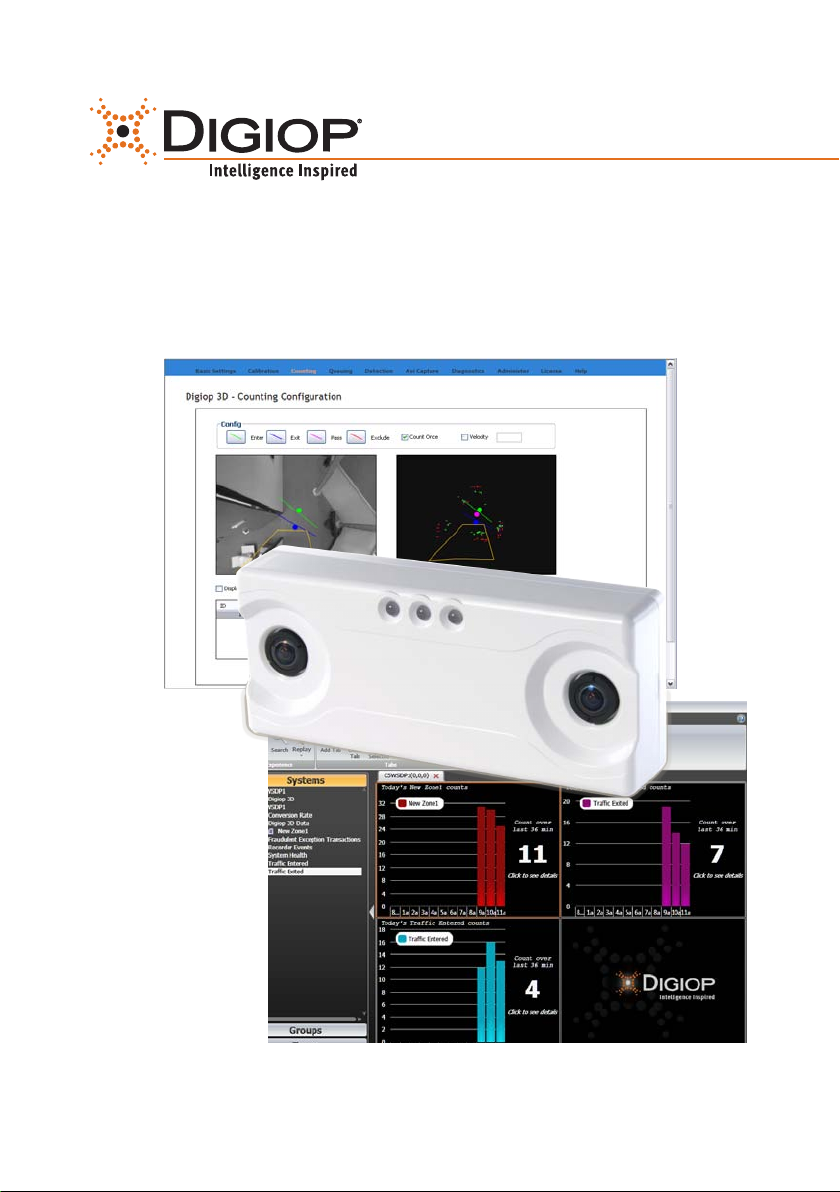
The DIGIOP® 3D camera oers multiple advantages over t raditional data collection devices and video analytic plat forms. The camera
consists of 2 lenses which gives it the ability to se e in stereo vision without the need of tradit ional scene calibration of 2D analytic
cameras. It ut ilizes this advanced stereoscopic c apability and object tr acking technology to provide accurate data under a broad
set of environmental conditions, such as high trac, dynamic lighting, and indoor and outdoor environment s. Based on the 3D
information, the system accurately distinguishe s between children, adults, and ot her objects such as shopping carts.
Combining this integrated intelligent camera into the DIGIOP ELEME NTS™ platform provides a ver y powerful counting solution with
video veric ation. Features include:
• Stereoscopic camera design (3D)
• 5 fps @ CIF resolution B/W video with 2.0 lux
• Provides queue and service point activit y monitoring data
• Real-time in-store data delivery to DIGIOP ELEMENTS ™ software with video verication
• Simple, intuitive web interface provid es full device conguration and management capabilitie s
• Extreme counting accurac y – typically greater than 95%
• Filters objec ts based on height, shape and size (i.e. children, shopping car ts and strollers as desired)
• Robust and accurate metrics across a broad set of environments: indoor/outdoor and high trac
• Adjusts automatically to environmental changes: lighting, temp erature, etc.
• Digital I/O and RS- 485 support
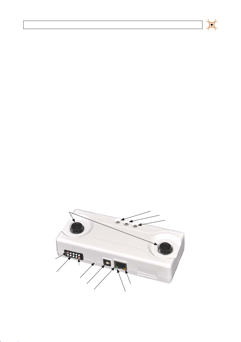
1.1 Controls and Indicators
Stereo Camera
Lenses
Pin 1
Pin 10
GPIO Panel
Reset but ton
Aux Power Port
Ethernet Port
Status LED 3
Status LED 2
Status LED 1
Ethernet Link LED
Ethernet Activit y LED
1DIGIOP® 3D Camera User Manual
Page 10
SECTION 1: OVERVIEW
1.1.1 LED Light Functions
Status LED 1 – Currently unused except during the boot sequence.
Status LED 2 – Blinks at a 3 second inter val to indicate the camera connec tion status with either a time sync server or data server.
If the LED is amber the camera cannot conne ct with either server, if the LED is green the camera can connect to at least one of thes e
servers.
Status LED 3 – If this LED is red, the DIGIOP ® 3D camera has rever ted back to its default factory s ettings and has an IP address of
192.168.1.7. This LED is also used wit h the manual reset button, for more information s ee “Using the Manual Reset But ton”.
The normal startup sequence is as follows:
1. All LEDs blink green.
2. Two LEDs illuminate red for 5 seconds.
3. Three LEDs illuminate red for 10 seconds.
4. Three LEDs blink amber.
5. One LED illuminates green for 1 se cond indicating the startup of the DIGIOP® b oot sequence.
6. One LED illuminates green and one LED illuminates amber for 15-20 seconds.
7. The middle LED blinks green or amber to indicate the server connec tion status.
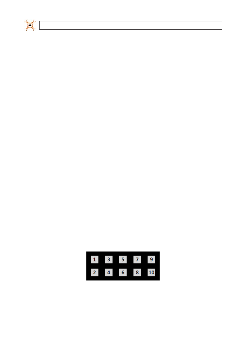
1.1.2 GPIO panel
The GPIO panel provid es a terminal block for 1 alarm input, 2 output and RS-485 controls.
GPIO Panel pins numbers
2
www.digiop.com
Page 11
SECTION 1: OVERVIEW
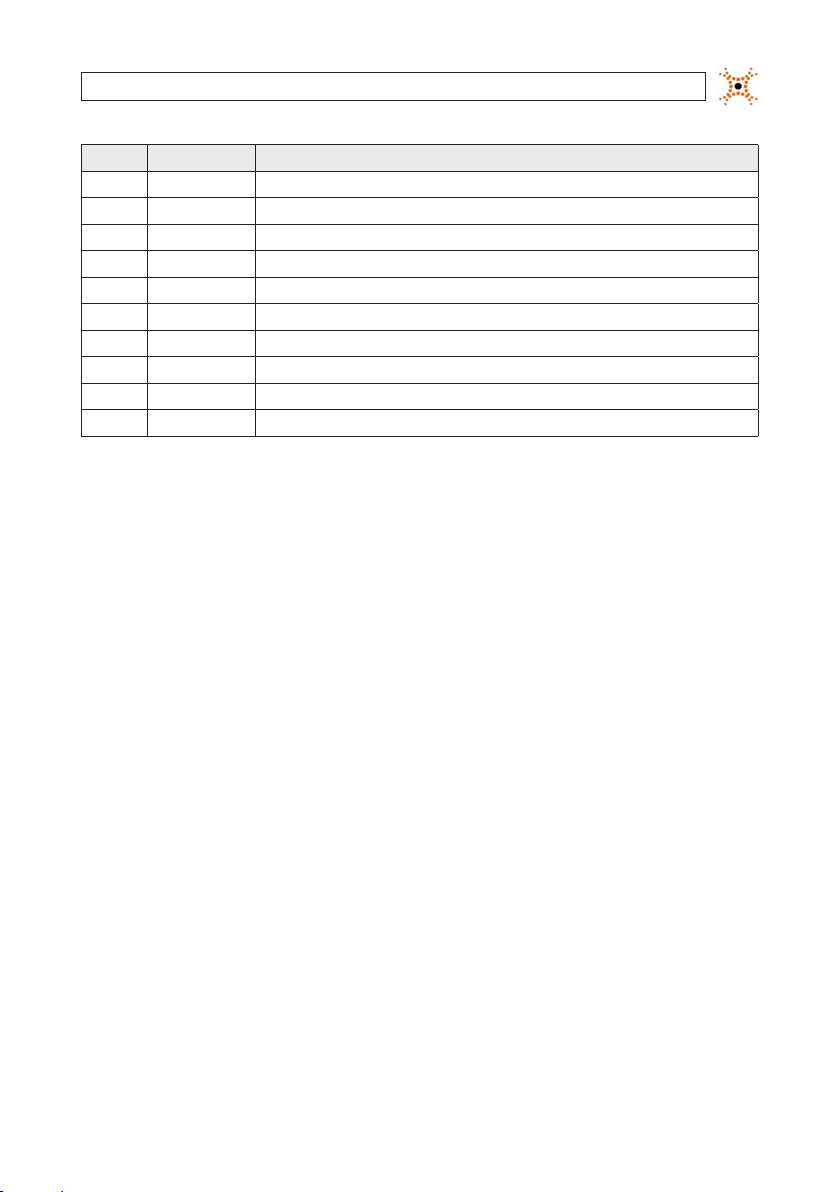
Pin N ame Funct ion
1 GND Ground fo r RS-485
2 GND Ground fo r RS-485
3 IN2_GND / R S485A Ground fo r opto-isola ted input 2 / RS4 85A
4 OUT2_G ND Ground fo r opto-isola ted output 2
5 IN2 / RS4 85B Opto-i solated input 2 / R S485B
6 OUT2 Opto-i solated open -collecto r output 2
7 IN1_GND Ground fo r opto-isola ted input 1
8 OUT1_GND Ground fo r opto-isola ted output 1
9 IN1 Opto-i solated input 1
10 OUT1 Opto-i solated open -collecto r output 1
1.2 Functional description
1.2.1 Default Conguration Parameters
DIGIOP® 3D camera ships with default conguration parameters. The se values, they can be found in the appendix of this document.
To reset the DIGIOP® 3D c amera to the default parameters, access the calibration page and click the Defaults button.
1.2.2 Saving Conguration Settings in the DIGIOP® 3D camera
Most pages in t he DIGIOP® 3D camera Conguration Application have Save, Prev iew, Reset, and Def ault buttons. The DIGIOP® 3D
camera has two methods to store conguration information:
Camera RAM – Temporary memor y used to preview the ee cts of conguration change s. All settings writ ten to this
memory are los t whenever the camera power is res et.
Flash Memor y – Permanent, non-volatile memor y used to save conguration change s. The values saved also become the
new values for the reset but ton.
The following but tons are used to save to each of the memory types:
Preview – Applie s changes to the camera RAM whic h allows you to preview the eect s of a change without overwr iting
the current settings. Changes will remain in eect until they are reset by using the re set button or the until the c amera is
power cycled. You can click save to keep the previe wed settings.
Save – Permanently saves all page changes or p reviewed settings to ash memory on the c amera. Saved values are applied
and become new reset values for the reset but ton.
3DIGIOP® 3D Camera User Manual
Page 12
SECTION 1: OVERVIEW
The following but tons are used to reset values and object s back to either their last saved or f actory default values:
Reset – Rese ts the previewed or changed values back to the las t saved values.
Default s – Resets values back to the f actory defaults. The values will not be permanently saved until you click Save.
1.2.3 DIGIOP® 3D camera and Oracle® Java™
DIGIOP® 3D camera uses Java applet s on most conguration applicat ion web pages. If you are connect ing to the DIGIOP® 3D camera
through Microsoft® Windows® Remote Desk top Services or a Citrix® server and using early versions of Java, some Java applet s may
not load. Ensure that you are using the latest version of Java.
1.2.4 Data Quality
When congured properly, the DIGIOP® 3D camera should achieve 95% or greater in counting accurac y over a sample of 100+
visitors. Typically, the error in counting is under count ing. When this device os congured properly:
• The lens is appropriate for the mounting height and mounting angle
• The DIGIOP® 3D camera can fully see people, unobs tructed, in both lenses
• The counting lines are p ositioned so that a person is tracked for a minimum of three feet (90 cm) prior to crossing a line
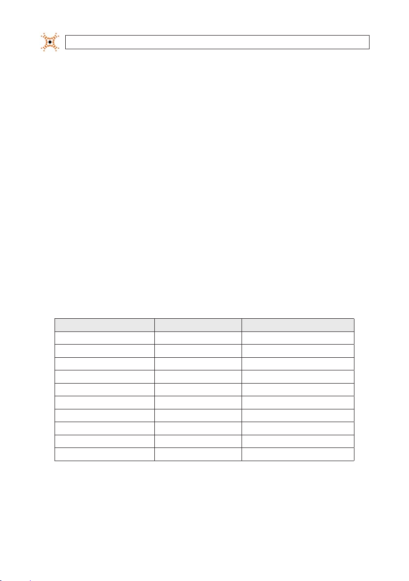
The following condi tions can impact system p erformance.
Condit ion Impac t Automat ed Detecti on
Lightin g level – too dark disable s counting yes
Lightin g level – too brigh t dis ables countin g yes
Calibrat ion Failure disable s counting yes
Shaking C amera unpredi ctable no
Tall Moving Obj ects over count ing no
Un-even S urface* und er counting no
Rain (heav y) under coun ting no
Dirt y/Scratched Le ns** under coun ting no
Transparen t/Translucent O bjects* ** unpred ictable no
Noisy Dat a unpredi ctable yes
* The DIGIO P® 3D camera ass umes that peo ple are walking on e ither a at or evenl y sloped sur face. All point s 4 feet on each sid e of the counting l ines should have a
maximum h eight variance of 12 in ches or 30 centim eters.
** Depen ding on the sever ity, this will ap pear as a calibrat ion failure and w ill be automati cally detec ted.
*** The D IGIOP® 3D camer a should not be mo unted so that it is a ttempting to co unt people thr ough glass.
4
www.digiop.com
Page 13

SECTION 1: OVERVIEW
1.2.5 XML Metric Data Delivery
Once congured and ins talled, the DIGIOP® 3D camera sends XML data packet s containing metric data to the congured delivery
address and por t at a congurable time interval and aggregation level. The data delivery address, por t, and delivery frequenc y are
set from the web-based conguration applic ation.
1.2.6 Data Buering
The DIGIOP® 3D camera will buer the count data for up to 10 days should a network or power outage occur that prevents it from
delivering to the ser ver. The device writes packets to vo latile memory every minute and saves data packets to non-volatile memor y
every three minutes. Buere d data is sent to the server in XML fo rmatted packets.
1.2.7 Shopping Cart and Object Filtering
The DIGIOP® 3D camera has three methods of ltering out unwanted objec ts to prevent them from being counte d and/or tracked:
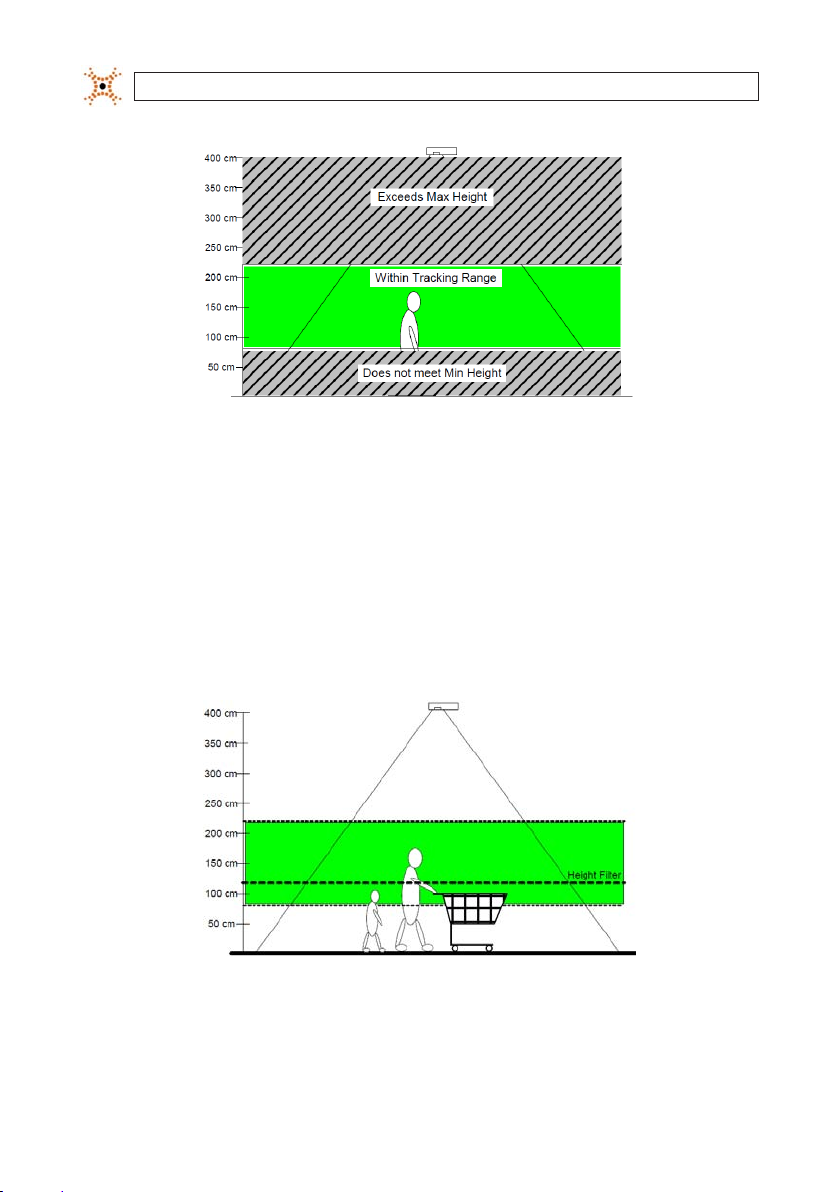
1. Dened Tracking Range – Prevents obje cts or parts of objects f rom being tracked based on minimum and maximum
height settings.
2. Shopping Cart – Eliminates shopping carts or objects similar to shopping car ts based on how well they t a pre-dened
model of a shopping c art.
3. Tall Objec ts – Eliminates balloons, ladders, and other tall objec ts by determining whether their average height (as
calculated by the DIGIOP® 3D) exceeds a thre shold height value congured in the DIGIOP ® 3D camera.
DEFINED TRACKING RANGE
The DIGIOP® 3D camera allows you to congure minimum and maximum height s for tracking. All object s that fall between the
minimum and maximum heights are tracked. O bjects outside of the range are exclude d from tracking. The maximum and minimum
height settings are set at 220 cm an d 70 cm by default. These parameter s can be found on the Tracking -> Segmentation subtab. DIGIOP® recommends that you not change these set tings.
5DIGIOP® 3D Camera User Manual
Page 14
SECTION 1: OVERVIEW
Tracking range height
1.2.8 Shopping Cart and Child Filtering
For shopping car t and child ltering, the DIGIOP® 3D camera uses the object height and an object-shape mo del. The camera
compares the obje ct height to a Height Filter threshold d ened in the Tracking->Basic sub tab. If the objec t is less than the height
specied in t he height lter or the object matche s the basic shape model for a shopping cart, the c amera does not count the objec t.
However, it will still track t he object. The same applies to the counting and tracking of children.
For example, a DIGIOP® 3D camera tracks a person pushing a shopping cart, and a child as t hree objects. Each of the three fall wit hin
the dened tr acking range.
6
People and shopping car t within the tracking range
www.digiop.com
Page 15
SECTION 1: OVERVIEW
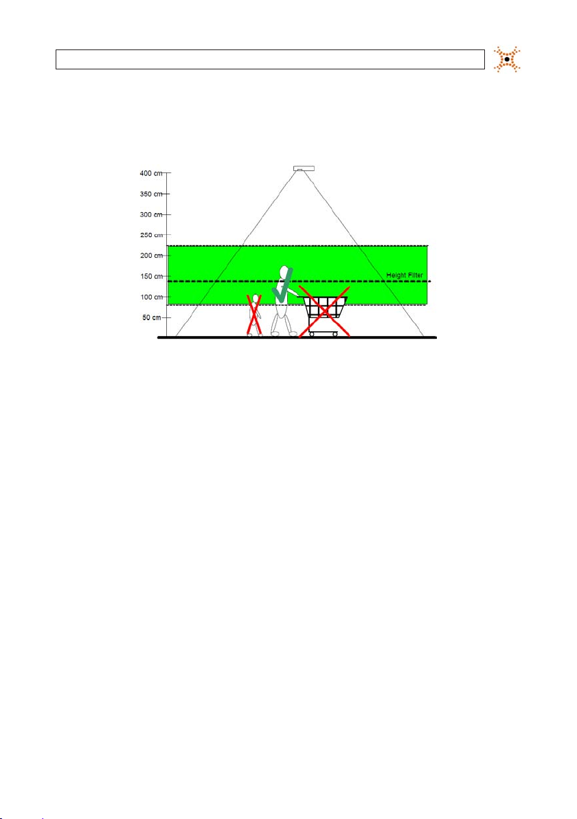
The camera compares the person, child, and the shopping cart to the shape model of a shopping car t The cart is excluded from
counting because it does not exceed the Height Filter and because it matches the shape mo del of a cart. The child is ltered out as
well based on the height lter.
Excluded objec ts
For more information on enabling car t ltering, see “Setting Object Filtering Options” later in this manual.
1.2.9 Tall Object Filtering
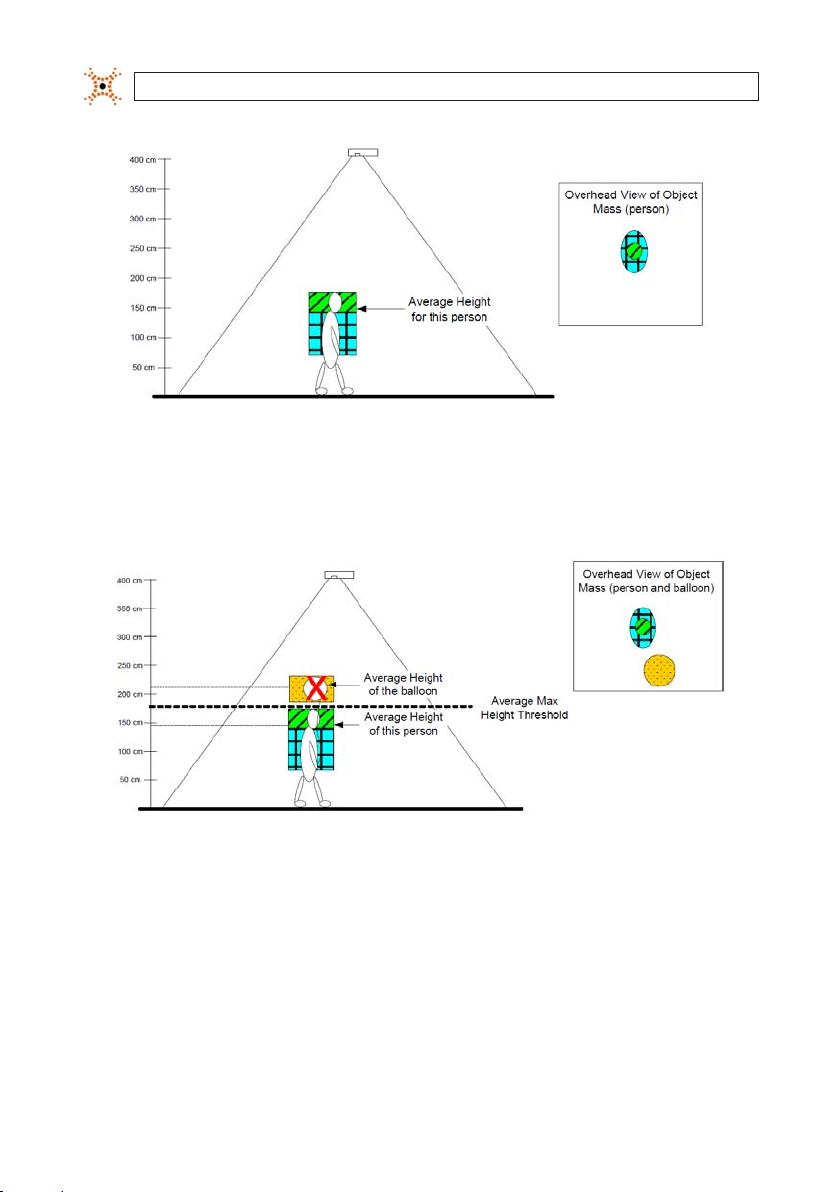
When ltering out t all object s, the DIGIOP® 3D camera uses an average height calculation, an e stimate of the average height of an
object based on all mass that the camera determines to be part of the object . Because most people are generally within one height
range (100 cm – 80 cm) and most other o bjects (balloons, ladder s, products, etc.) are above 180 cm. By def ault, the camera is
congured to lter out any object that has an average mass height above 180 cm. DIGIOP® recommends that you not change this
setting.
The camera begins tracking an object when the object exce eds the minimum tracking height. The colored boxes below show the
typical areas of a person that are t racked, and considered as part of the object ma ss, by a DIGIOP® 3D device. The DIGIOP® 3D cam era
estimates the height of all mass containe d in the green and blue boxes and calculates an aver age height. This average height is
always less than the actual height of the person. Once the DIGIOP® 3D camera calculates the average mass height of an objec t, it
compares the thre shold set on the Tracking -> Tracking sub tab -> Max Average Height eld.
7DIGIOP® 3D Camera User Manual
Page 16
SECTION 1: OVERVIEW
Object mass within cam era tracking range
Consider what happens when the DIGIOP® 3D camera encounters a person carr ying a balloon. The calculated average mass height
of the person is within the acceptable r ange so the person is eligible for counting. The balloon e xceeds the maximum average height
of 180 cm and is ineligible for counting.
8
Average mass height calculation for pe rson and balloon
www.digiop.com
Page 17

SECTION 2: INSTALLATION
SECTION 2
Installation
2.1 Setting the DIGIOP® 3D Camera IP Address
The DIGIOP® 3D camera is congured with the default IP address of 192.16 8.1.7. If the default settings are incompatible with your
network , use the following procedure to recongure these se ttings. Consult with you net work administrator for recommendations.
In general, the preferred method for changing the camera networ k conguration is:
1. Disconne ct your PC from all networ k connections.
2. Manually assign your PC an IP address of 192.168.1.10.
3. Connec t the DIGIOP® 3D camera direc tly to your PC.
4. Connec t the DIGIOP® 3D camera to the PoE injector. Once connected, you can change the IP address by using the
conguration application built into the D IGIOP® 3D camera.
Complete the steps in sections 2.1-2.4 to initially set the IP address for your camera:
2.1.1 Manually Set a Static IP Address on Your PC
Before conne cting the DIGIOP® 3D camera to p ower or to your PC, you must rst set the IP address on your P C.
As a best pr actice, DIGIOP® recommends setting your PC to use multiple st atic IP addresses. The rst static IP address should be a
192.168.1.### address to connec t to cameras that are shipped to you from DIGIOP. The second IP address should be an IP address
on the network where the DIGIOP® 3D camera will be ins talled. This will allow you to connect to the DIGIOP® 3D camera during the
installation af ter the camera is mounted and conne cted to the client networ k.
Complete the following steps to congure your PC to use multiple IP addresses:
1 Complete the Pre-Ins tallation Checklist in “Appendix B – Pre-Install Checklist ” of this manual.
2 Disconnect the Ethernet (CAT5) cable from your PC and disable any wireless connections that you may have.
3 Turn your PC on i f you have not already done so.
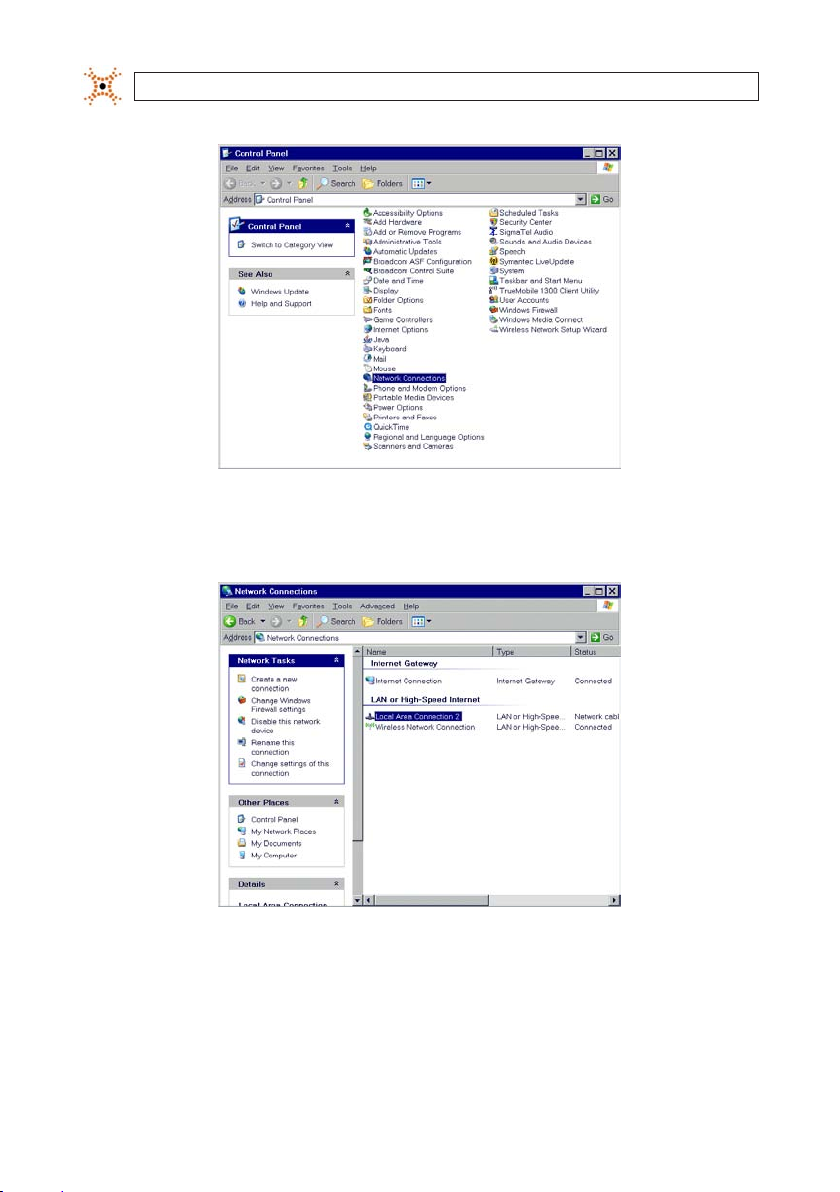
4 From t he desktop of the PC, click Star t and select Control Panel. The Control Panel opens.
9DIGIOP® 3D Camera User Manual
Page 18
SECTION 2: INSTALLATION
Typical Windows XP Control Panel
5. Double -click Network Connec tions. The Network Connections window will open.
Typical Windows XP Network Connections win dow
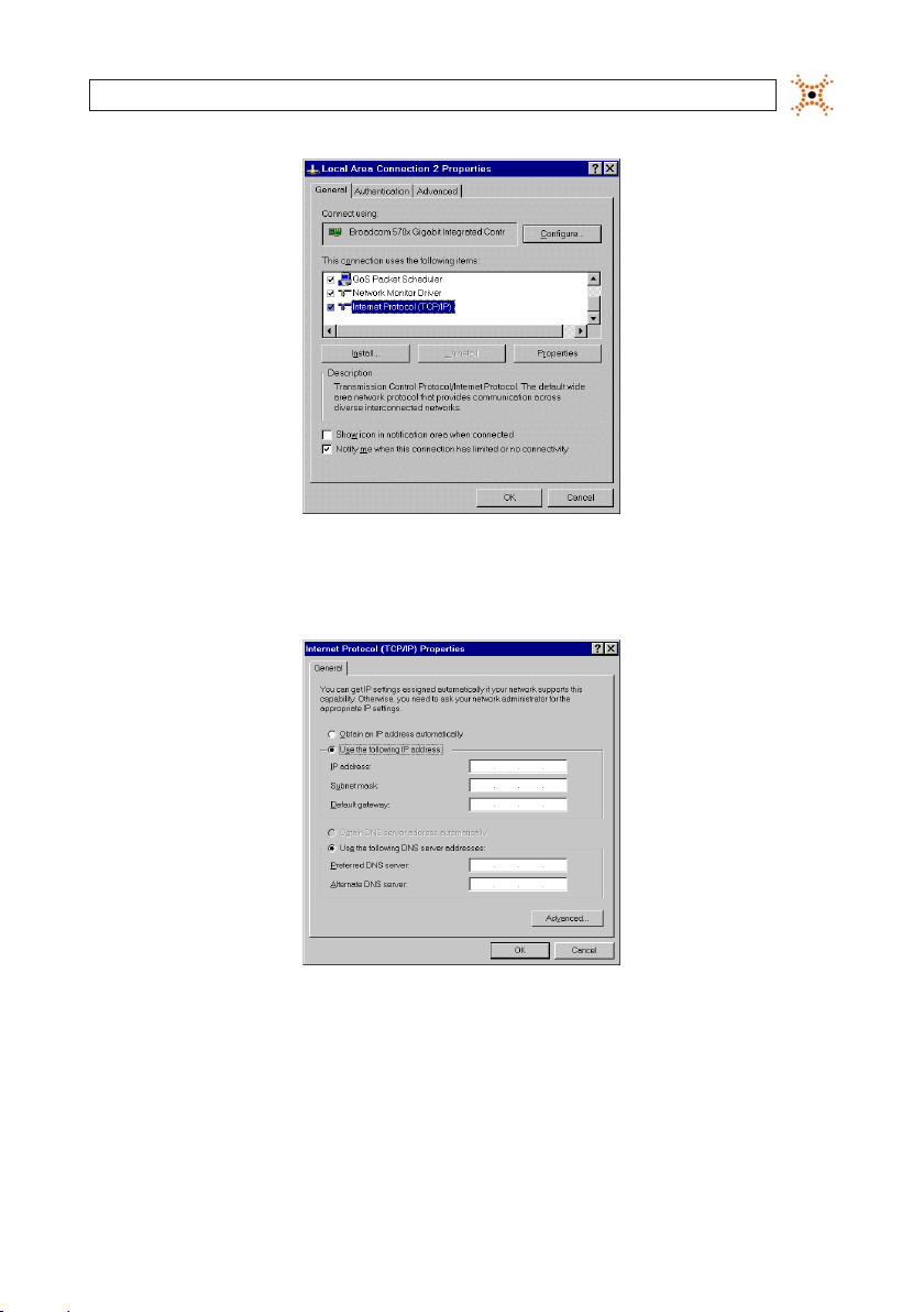
6. Double -click Local Area Connection. The Local Area Conne ction Properties dialog appear s.
10
www.digiop.com
Page 19
SECTION 2: INSTALLATION
Local Area Connections Proper ties window
7. Selec t Internet Protocol (TCP/IP) and click Properties. The Internet Protocol (TCP/ IP) Properties dialog box appears.
Internet Protocol (TCP/IP) Properties dialog box
8. Record the current set tings in this window so that you can change them back af ter you set the network par ameters on the
camera if necessary.
9. Selec t Use the following IP address and type an IP address for your computer to use (e.g. 192.168.1.10).
11DIGIOP® 3D Camera User Manual
Page 20
SECTION 2: INSTALLATION
NOTE
Only the last oc tet of the laptop IP address shoul d be dierent from that of the camera (e.g. camera = 192.168.1.7,
PC = 192.168.1.10).
10. Enter 255.255.255.0 in the Subnet Mask eld.
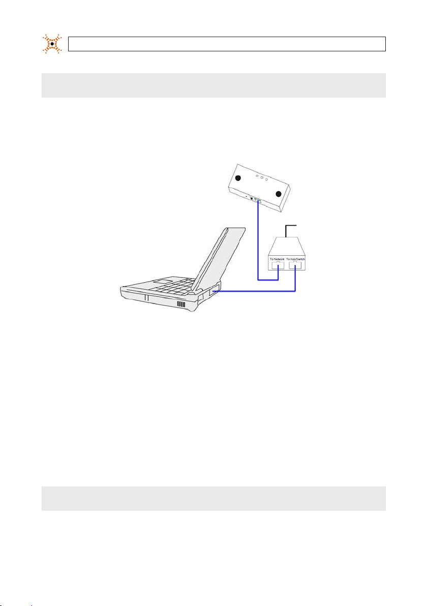
2.1.2 Connect the DIGIOP® 3D camera to your PC
To Power
Source
Typical Conguration for Initial IP address re- conguration
1. Plug the Power-over-Ethernet (PoE) injec tor or PoE switch to a power outlet.
2. Plug an Ethernet (CAT5e) cable from the “In” por t (outside por t) of the DIGIOP® 3D camera to the “Network” port of the PoE
injector or s witch.
3. Plug an Ethernet drop cable from the Switch port of the PoE injec tor into the Ethernet por t in your computer.
2.1.3 Set the IP Address of the DIGIOP® 3D camera
After set ting the IP address on your PC and connected it to the DIGIOP® 3D camera and PoE injector, setup t he IP address of the
camera as follows:
Before you can use the DI GIOP® 3D camera web pages, you must ins tall Java Runtime Environment (JRE 1.5.0_04 o r higher)
on your PC.
12
NOTE
www.digiop.com
Page 21
SECTION 2: INSTALLATION
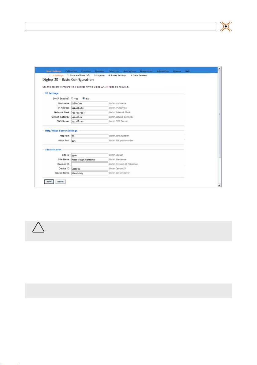
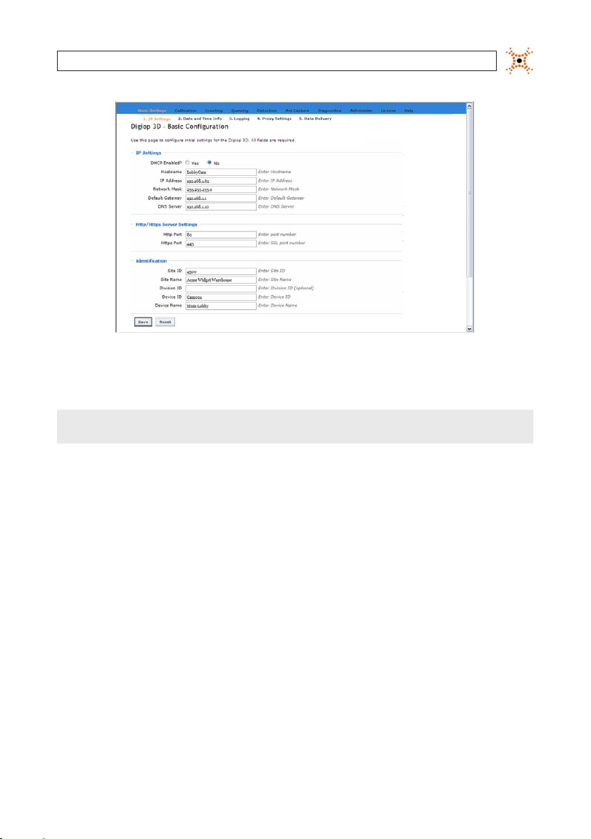
1. Open a web browser and enter http://192.168.1.7 into the URL address eld, then pre ss Enter. The DIGIOP® 3D camera
Conguration application Basic Se ttings – IP Settings page loads into the browser.
Basic DIGIOP® 3D camera Conguration – IP Set tings page
2. Enter the ne w IP address that the DIGIOP® 3D camer a into the IP Adress eld.
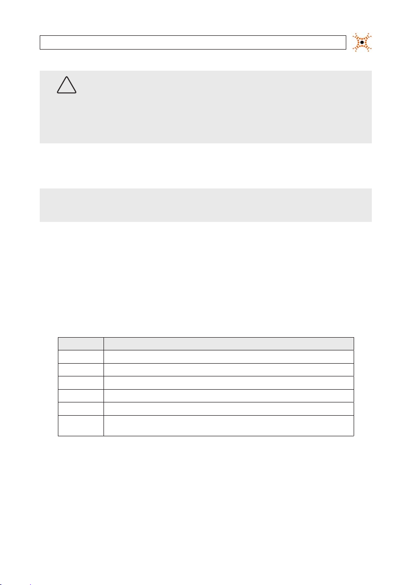
CAUTION
DIGIOP® stro ngly recommend s that you DO NOT USE DHCP to congu re your camera.
Use static IP addressin g only.
3. Enter the Network Mask, Default Gateway, and DNS Server (optional) addresse s for the network where your c amera
will be installed.
4. Set the p orts to use for HTT P and HTTPS communication in the HTTP Port and HTTPS Por t elds.
NOTE
Consult with your Net work Administrator for recommende d port settings for you r installation. The the HTTPS po rt option
requires a license that enab les encryption.
5. Enter the identication inf ormation (Site ID, Site Name, Device ID, Device Name), into the appropriate elds.
6. Click Save to s ave your changes.
13DIGIOP® 3D Camera User Manual
Page 22
SECTION 2: INSTALLATION
When you change the I P address on a DIGIOP® 3D camera and c lick Save, you will lose connectivit y to that camera for
!
WARNING
several seconds while it re-con gures itself with the new netwo rk settings. To reconnect to the camera, enter the new I P
address into the UR L address bar of the browser and press e nter to reconnect.
If you are assigning t he camera to a dierent subnet, you will lose connec tivity to the camera until you connect t he to the
camera to the assigned subne t and access it there, or until you modif y your PC‘s network settin gs to include the subnet.
The camera is now read y to be connected to the network using its new IP address and et work conguration. Disconnect all cables
and prepare for mounting the camera.
7. Complete the steps in this section for each additional DIGIOP® 3D camera being ins talled.
8. Set the network conguration of your PC back to its original s ettings.
2.2 Mount the DIGIOP® 3D camera
This sect ion describes some basic mounting guidelines f or mounting DIGIOP® 3D camera.
NOTE
!
WARNING
Before mountin g any camera(s), you should check the Camera/Lens Selection Tables in the app endix of this document
to ensure that you are using the ap propriate lens for your installa tion height and door width.
If you are mounting t he DIGIOP® 3D camera outdoors, refer to Eliminating Tracking D isabled Messages in the
appendix of th is document to congure the camera for outdoo r tracking.
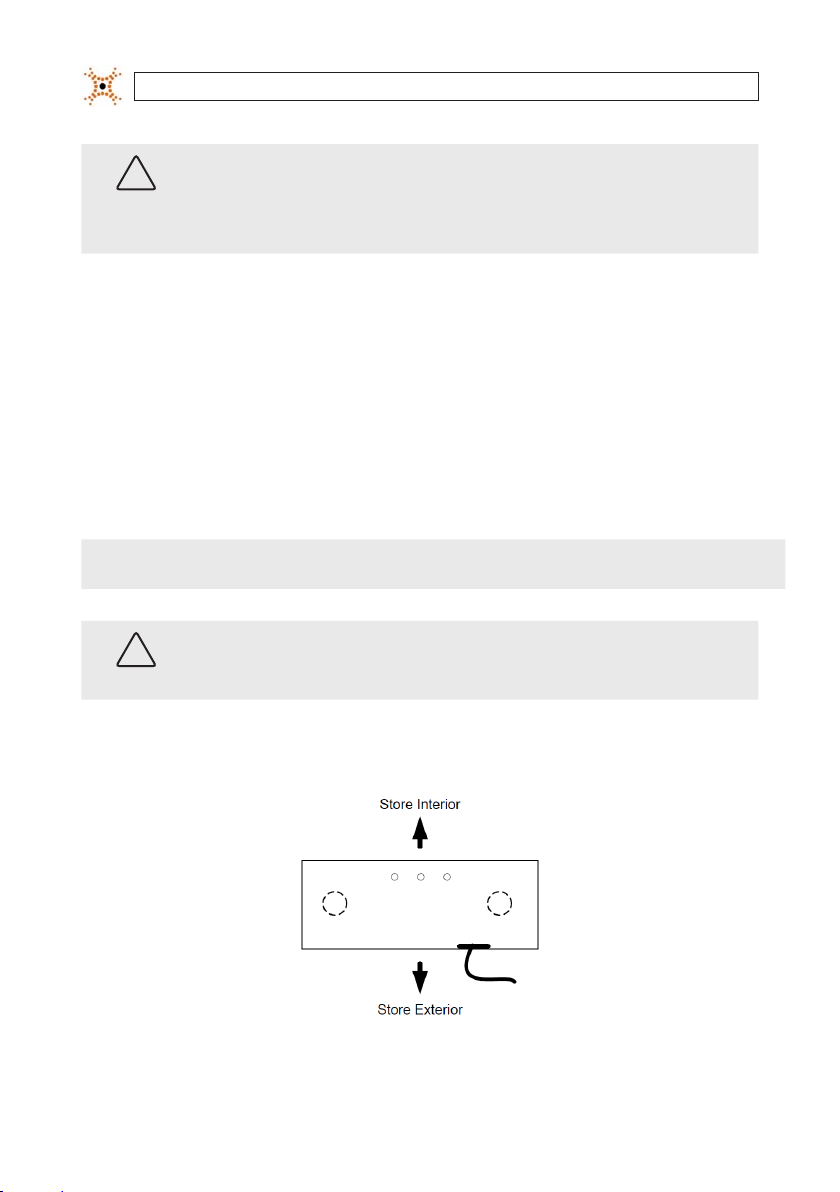
The camera should b e mounted so that the camera lens coverage area is of maximum width in respec t to the entry way (see the
gures Camera Orientation – Top View and Sample Coverage Area.
Camera Orientation – Top View
14
www.digiop.com
Page 23

SECTION 2: INSTALLATION
Sample coverage area
Camera can be ins talled via:
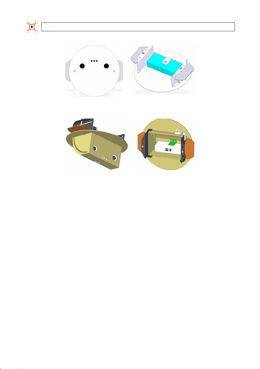
• Standard mounting bracket with a ¼”-20 threaded post.
• Surface mount (see Surface Mount) – Used for loc ations where a minimal disturbance to ceiling is required.
• Recess mount (se e Recess Mount) – Used for drop ceiling mounting. Mounting brac kets attach to the camera using 1/4”-20
threaded pos t.
• Mount at heights between 2.4 metre s (8 f eet) and 20 metres (65 feet) (with appropriate lens).
• Mounted in a downward lo oking orientation and level in both t ilt and yaw such that the camera is looking straight down (if
possible). The DIGIOP® 3D camera soft ware also supports mounting at angles in sites where 90 degre e downward looking
mounting is not pos sible (additional license re quired).
• Mounted over fairly level surface (mounting over stairs or highly sloped sur faces is not recommended).
• Mounted in such a way that the entry or e xit corridor is positione d at or very close to the center of the camera eld of view.
• Adequate space should be provided in the mounting bracket or mounting holes to allow for one 10/100BaseT CAT5e Ethernet
cable to be run above t he mounting location.
• When using recess mounting bracket s, a maintenance loop of at least 3 feet should b e stored in the ceiling above the mounting
location.
Surface mount bracket
15DIGIOP® 3D Camera User Manual
Page 24
SECTION 2: INSTALLATION
Recess mount example
Tilting-recess mount e xample
2.3 Connect the Camera to a Power-over-Ethernet (PoE) Net-
work
All DIGIOP® 3D cameras require connec tions to a LAN with Power-over-Etherne t (PoE) on 802.3af standards. PoE allows for a
combined power and ne twork connection using a standard CAT-5 Ethernet cable. This section describe s how to connect the
DIGIOP® 3D camera to the networ k/PoE cables. There are three recommended methods of connec tion:
• Connect using an end-span PoE switch.
• Connect using single-por t PoE Injector.
• Connect using multi-por t mid-span PoE Injector.
16
www.digiop.com
Page 25
SECTION 2: INSTALLATION
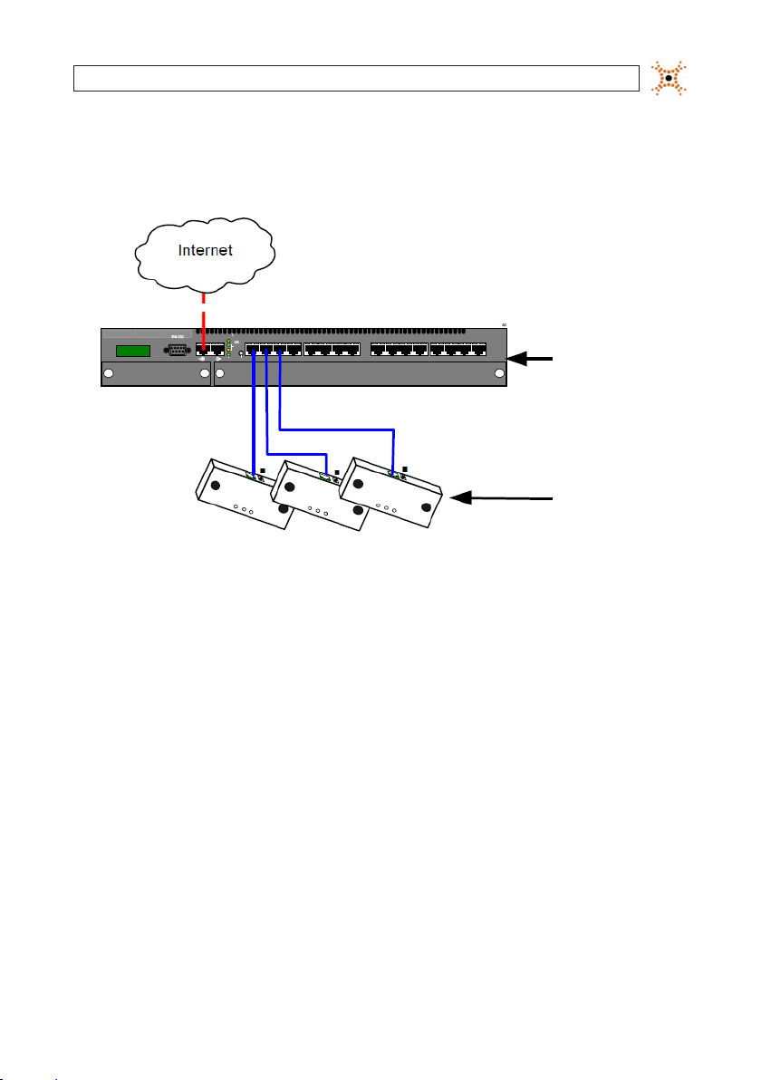
2.3.1 Connect using an end-span PoE switch
The following diagram show how the camera should be connected to an end-span PoE switch.
Data
Data and
Power
Ethernet end-span switch imple mentation
Ethernet
End-span
Switch
DIGIOP ® 3D Camera
17DIGIOP® 3D Camera User Manual
Page 26
SECTION 2: INSTALLATION
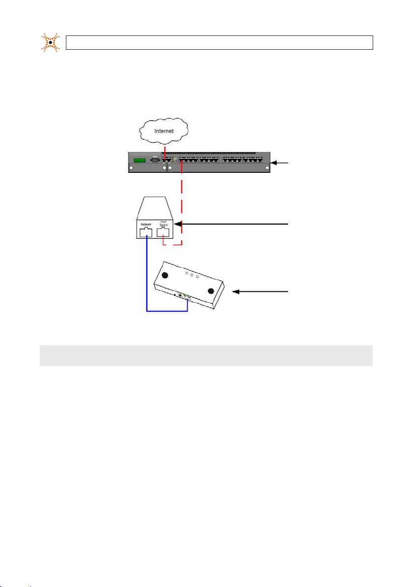
2.3.2 Connect Using Single-port PoE Injector
The following diagram shows how DIGIOP® equipment should be connected when using a Power-over-Ethernet Injector.
Data
Ethernet
Switch
Data
PoE
Injector
Data and
Power
DIGIOP ® 3D Camera
PoE Injector implemen tation
18
NOTE
No special cables a re required, all connections use standa rd CAT5e Etherne t cable.
www.digiop.com
Page 27

SECTION 2: INSTALLATION
2.3.3 Connect using multi-port mid-span PoE injector
The following diagram shows how DIGIOP® 3D camera should be conne cted when using a multi-por t mid-span PoE injector.
Ethernet
Switch
Data
Mid-span
PoE
Injector
NOTE
Data and
Power
DIGIOP ® 3D
Cameras
Mid-span PoE injector im plementation
After connec ting all cables, ensure that the net work lights are lit on the Etherne t ports of the DIGIOP ® 3D cameras. These
lights verif y that the components are connec ted.
19DIGIOP® 3D Camera User Manual
Page 28
SECTION 3: CONFIGURE THE DIGIOP® 3D CAMERA
SECTION 3
Congure the DIGIOP® 3D camera
The following se ctions describe how to con gure all required parameters wit hin the DIGIOP® 3D camera conguration application,
including:
1. Accessing the DIGIOP® 3D camera Conguration Applic ation.
2. Set ting the Date/Time options.
3.1 Access the DIGIOP® 3D camera conguration application
NOTE
To use the conguration appl ication, you must have Java Runtime Enviro nment version 1.5.0_04 or later install ed on your
computer.
When accessing the conguratio n application, use Microsof t® Internet Explorer® V 6.0 (or newer) or Moz illa® Firefox®.
1. Connec t the DIGIOP® 3D camera using one of the connection options shown in Se ction 4, “Connect Power-over-Ethernet
(PoE) System at the Site”.
2. Connec t a computer to the same networ k as the DIGIOP® 3D camera.
3. Open a web browser and typ e the IP Address of the DIGIOP® 3D camera in the Address Bar and press Enter. The congurat ion
application load s into the browser window.
3.2 Setup the Device Identication information
Metric data is s ent from the camera includes identifying information about the device in an XML p acket. You can use the
Identication group on the Basic Settings --> IP Settings sub -tab to set and edit this information.
NOTE
Complete the following steps to enter identi cation information for a device:
1. Click Basic Settings. The Basic Settings tab, IP Settings sub -tab appears.
If you are using the DIGIO P® Operational Database a nd the DIGIOP® Device Adapter to sto re metric data, set the Site ID. It is
used to register the device.
20
www.digiop.com
Page 29
SECTION 3: CONFIGURE THE DIGIOP® 3D CAMERA
Basic settings tab – IP set tings sub-tab
2. Type the Site ID, Site Name, Division ID, Device ID, and Device Name in the appropriate elds.
NOTE
The DIGIOP® D evice adapter will attempt to match the Site I D to a site ID in the Operational Database to au to-register the
camera to a site.
3. Click Save.
3.3 Set the Date/Time Options
Setting t he time in a DIGIOP® 3D camera requires connecting to t he time server. The time server may b e located on a local network,
or on the Internet .
1. Access the DIGIOP® 3D camera Conguration applicat ion.
2. Click Basic Settings. The Basic Settings page appears.
3. Click Date an d Time Info. The date and time settings appear.
21DIGIOP® 3D Camera User Manual
Page 30
SECTION 3: CONFIGURE THE DIGIOP® 3D CAMERA
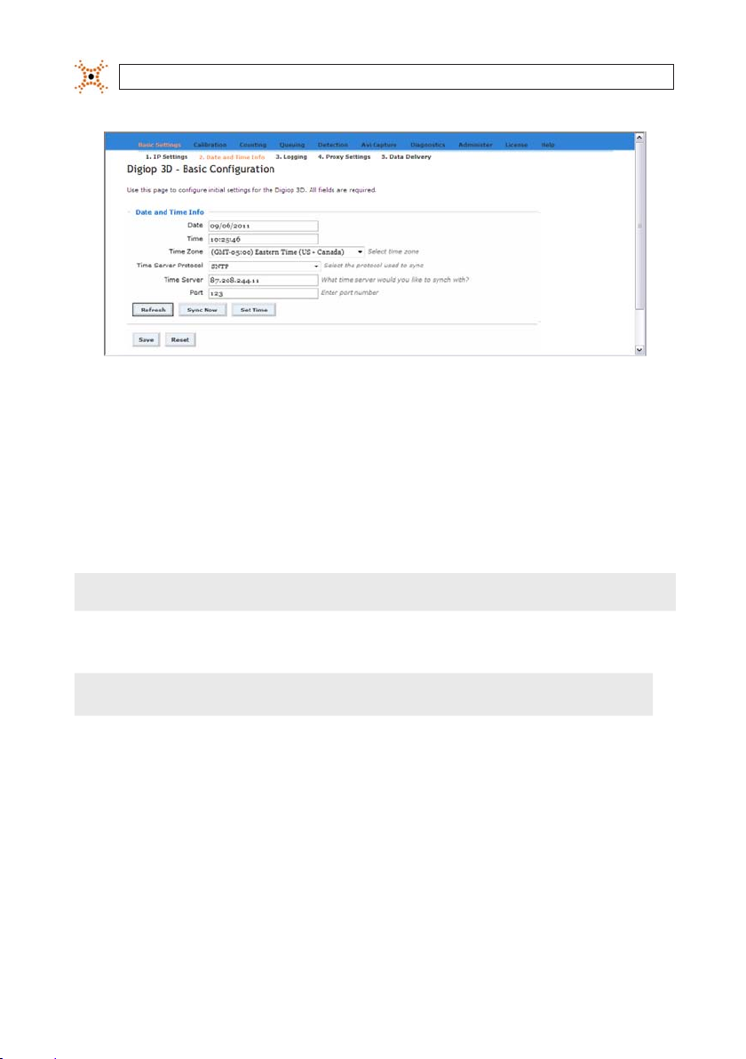
Date and Time Info tab
4. Click the Time Zone drop-down box and sele ct the appropriate time zone f rom the list. Set the time zone to the time zone
at the installation site.
5. Click the Time Server Protocol drop-down box and s elect the appropriate protocol. Enter the prefer red time server
protocol for your site. Consult with your network adminis trator for more information.
6. Enter the IP ad dress of a time server in the Time S erver eld.
NOTE
The time s erver serv ice will set the c amera time to UTC tim e, therefore t he time serve r can be running in a ny time zone.
7. Enter the Por t number from which the DIGIOP® 3D camera should at tempt to get a time synchronization.
NOTE
The time synchroni zation port and data deliver y port can be sent to the same IP Add ress and port if necessary. The defa ult
port numb er is 2000.
8. Click Save.
3.3.1 Testing Time Sync conguration
After you save the conguration settings for the time sync, c lick Sync Now to test the connection to the time sync server. When
you click Sync Now, a time sync re quest is sent to the IP address and port speci ed on the Date and Time Info p age. A success or
failure message is displayed at the top of the page depending on the synchronization outcome.
22
www.digiop.com
Page 31

SECTION 3: CONFIGURE THE DIGIOP® 3D CAMERA
3.3.2 Manually setting the system time
In some instance s, you may not have access to a time synchronization server and will need to manually set the time on the device.
Complete the following steps to manually set the time on the D3D-2500 camer a.
1. Click Date an d Time Info.
2. Enter the current date in the Date eld.
3. Enter the current time in the Ti me eld.
4. Click Set Time to set the time on the device to the date and time that you entered.
5. Click Save to up date the time.
3.4 Set the Data Delivery Address
1. Access the DIGIOP® 3D camera Conguration Applicat ion.
2. Click Basic Settings, the Basic Settings – IP Addre ss page loads.
3. Click Data Delivery. The Data Delivery opt ions appear.
23DIGIOP® 3D Camera User Manual
Page 32

SECTION 3: CONFIGURE THE DIGIOP® 3D CAMERA
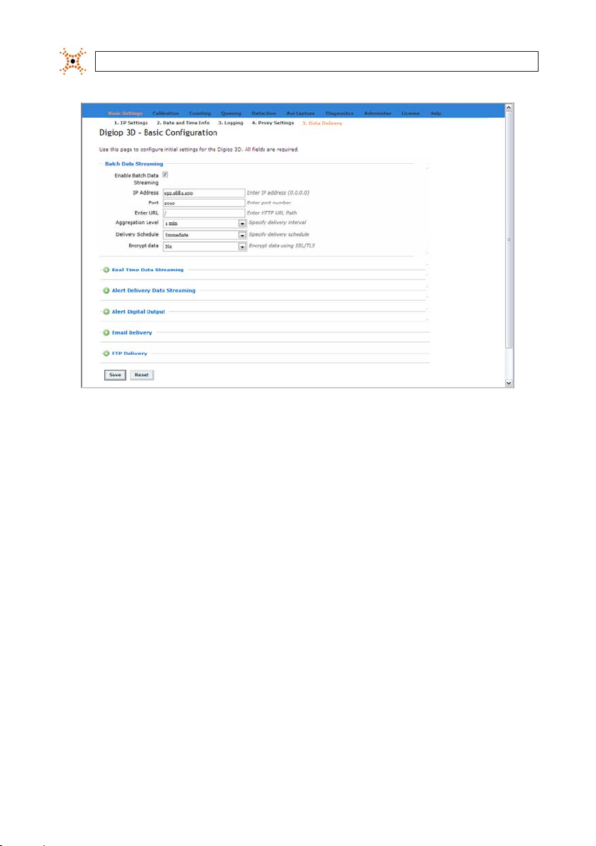
Basic Settings – Data Del ivery tab
NOTE
Batch Data Streaming is not a su pported method for the D IGIOP® D3D-2500 camera.
3.5 Optional Email Data Delivery
The Data Deliver y tab allows you to automatically send aggre gated daily metric data to an email account. Files are sent in SXML
format. Comple te the following steps to congure the email delivery:
1. Access the DIGIOP® 3D camera Conguration applicat ion.
2. Click Basic Settings, the Basic Settings – IP Address page loads.
3. Click Data Delivery. The Data Delivery opt ions appear.
4. Click Emai l Delivery to expand the email delivery opt ions.
24
www.digiop.com
Page 33

SECTION 3: CONFIGURE THE DIGIOP® 3D CAMERA
Basic Settings – Data Del ivery
5. Selec t the Enable Email Delivery check box to activate the Email Delivery elds.
6. Enter the re cipient’s email address in the Recipient eld.
7. Enter the sender’s email address in the Sender eld.
NOTE
Both the Recipi ent and Sender eld must contain the ema il address of a valid sender on the SMTP ser ver.
8. Enter the IP Address or Hos t Name of the SMTP Server in the SMTP Server eld.
25DIGIOP® 3D Camera User Manual
Page 34

SECTION 3: CONFIGURE THE DIGIOP® 3D CAMERA
!
WARNING
If you enter a Host Name f or the SMTP Server eld, you must also enter a valid D NS Server IP address in the IP Set tings group
on the Netwo rk tab.
9. Type the por t number used by the server in t he Port eld.
NOTE
If your SMTP Server doe s not require Authentication, skip steps 10 throu gh 12.
10. If your SMTP Server requires an Authenticat ion password, select the SMTP Server requires Authentication check box .
The User Name and Pass word elds become active.
11. Enter the user name for your SMTP Server in the User Name eld.
12. Enter the password for your SMTP Server in the Password eld.
13. Click the Aggregation Level drop-down arrow and select an aggregation level for the count repor t email (1 minute, 5 minute,
15 minute, 30 minute, 60 minute, and daily).
NOTE
Depending o n which option is selected, the camera will sen d an email listing the metric data fo r each 1 minute, 5 minute,
15 minute, 30 minute, or 60 minute time peri od over the previous 24 hours. For counting , if you select daily, the email will
contain a single enter and e xit count for the previous 24 hour period.
14. Type the time (in 24 hour notation) at which the DIGIOP® 3D camera should send the email in Deliver y Time eld.
The aggregate email contains data form midnight to midnight during the previous calendar day. For example, if the Deliver y
Time is set for 18:00, the c amera will send the count data for the previous day at 6 PM every day.
15. Click Save to save your changes. A conrmation message appears.
16. Click Yes to save your changes. An Info message appears at the top of the page.
17. Click Test Email Set tings to send a test email to the email address entered in the Recipient eld. A conrmat ion message
appears infor ming you that the email was successfully s ent.
NOTE
If you receive an error message, see the troublesho oting procedures in the appendix of t his document.
18. Check the email address in the Recipient eld to ensure that the test email arrives.
26
www.digiop.com
Page 35

SECTION 3: CONFIGURE THE DIGIOP® 3D CAMERA
Sample DIGIOP® 3D camera count data ema il attachment
3.6 Optional FTP data delivery
The DIGIOP® 3D camera can deliver metric les automatic ally to an FTP server at an hourly or daily interval. Files are s ent in XML
or pipe-delimited format. W hen FTP delivery is selec ted, the DIGIOP® 3D camera at tempts to use the passive FTP p rotocol. If the
delivery fails, the device then at tempts to use active FTP. Comp lete the following steps to congure the D IGIOP® 3D camera FTP
delivery:
1. Access the DIGIOP® 3D camera Conguration applicat ion.
2. Click Basic Settings, the Basic Settings – IP Address page loads.
3. Click Data Delivery. The Data Delivery opt ions appear.
27DIGIOP® 3D Camera User Manual
Page 36
SECTION 3: CONFIGURE THE DIGIOP® 3D CAMERA
Data Delivery options
4. Click FTP Delivery to expand the F TP Delivery section.
28
www.digiop.com
Page 37

SECTION 3: CONFIGURE THE DIGIOP® 3D CAMERA
FTP Delivery – expa nded
5. Click the Enable FTP Delivery che ck box to activate the FTP f unctionality.
29DIGIOP® 3D Camera User Manual
Page 38

SECTION 3: CONFIGURE THE DIGIOP® 3D CAMERA
6. Enter the IP ad dress of the FTP Server in the FTP Server eld.
7. Enter the F TP port to be used in the Por t eld. The port number is usually 21.
8. Dene the le naming convention for t he data les in the File Naming Convention eld. You can choo se to include several
variables from the DIGIOP® 3D camera by entering a “#” fo llowed by the one let ter variable. Any characters that you type
that are not immediately preceded by a “#” will b e included in the le name as normal tex t. See the table below for variable
denitions:
NOTE
Variabl e Denit ion
The interface prohib its you from using le names th at contain Microsoft Windows reser ved characters (/
,\,?,&,*,:,|,”,<,>). Additio nally, the DIGIOP® 3D camera prohibit s the uses of spaces in le names.
#S Inserts the Site Name f rom the Basic Settings t ab->IP Settings sub-tab.
#I Inserts the Site ID from the Basic Settings tab->IP Settings sub-t ab.
#D Insert s the Date of the data contained in the sent dat a le formatted YYMMDD.
#T Inserts the Time of the last data bucket included in the sent data le format ted HHMMSS.
#M Inser ts the MAC address of the DIGIOP ® 3D camera device sending the data le for matted XX-XX-XX-XX-XX-XX.
For the following e xamples, assume the site name is set to Grocery1 and the site ID is set to 987.
File Nami ng Conventio n Field Result ing File name
#S.PCNT.#I.# D.#T.#M.dat Gr ocery1.PCNT.987.090226.1400 00.00-b 0-9d-70-01-0 5.dat
#S_#I _#T Grocer y_987_14000 0
countdat a-#S-#I- #D#T.txt cou ntdata-Gro cery1-987-090226140 000.tx t
#T#D_#M.c sv 14000 0090226_ 00-b0- 9d-70-01-05.c sv
NOTE
The FTPS option is not a vailable at this time. In the FTPS eld , select No.
9. Enter the F TP user name required to login to the F TP server in the Username eld.
10. In the Password eld, enter the p assword for the Username you entere d in the previous step.
11. In the Director y eld, enter the destination directory for the FTP les. If this eld is lef t blank, les are delivered to the FTP
root directo ry of the user.
30
www.digiop.com
Page 39

SECTION 3: CONFIGURE THE DIGIOP® 3D CAMERA
12. Click the Aggregation Level drop-down list. Select the frequenc y at which the metric data will be s tored in the les. The
camera can store data in intervals of 5, 15, 30, and 60 minutes.
13. Click the Deliver y Format drop-down and select the for mat for the data les sent over FTP. There are two options, Pipe
Delimited and XML.
Pipe Delimited Format: The Pipe Delimited f ormat sends data for each repor t zone with the relevant information
separated by a pip e character “|”.
XML Format: The XML format sends metric data in an XML le similar to the XML packets that are sent ou t using the Batch
Data Streaming option. See the DIGIOP ® 3D camera Programmer Guide for more information on the XML format.
14. Click the Deliver y Schedule drop-down box and selec t the frequency at which the FTP le is delivered. You can have an
FTP le delivere d each hour or you can have the le delivered once daily at a scheduled time.
15. If you selected Daily in the previous step, enter a delivery time in the Delivery Time eld. The Delivery Time should be
entered in 24 hour notation (00 :00-23:59).
16. In the Maximum Retrie s eld, enter the maximum number of times the camera should at tempt to reconnect to the FTP
server to send the les when a failure occurs. If the Ma ximum Retries eld is set to zero, the camera will continue to ret ry
indenitely until it successfully s ends the le.
17. In the Retr y Interval eld, enter the length of time, in s econds, the camera will wait before attempting to re connect to the
FTP ser ver. T his value can range from 1 to 599 seconds.
18. Select the Por t Range check box if you are using an ac tive FTP server and want to limit the port range that is used for
connectio ns. Enter the port range into the Lowest Port eld and the Highest Port eld.
19. If you want to pass an IP address to your rewall that is dierent from the DIGIO P® 3D camera IP address and FTP server,
select the External IP Override checkbox, then enter the IP addre ss.
20. Click Test FTP Settings to verify that the camera can connect to the F TP server.
NOTE
This test does not veri fy that a le can be transferred to the ser ver. It only veries tha t the camera can log in to an FTP server
at the specied IP ad dress and port number usin g the username and password specied.
You may encounter the following erro rs when conguring the FTP delivery options:
— Failed to connect 36: Incorrec t Server IP Address
— Failed to connect 64: Incorrect Port Number
— Failed to connect 530 password not accepted: Incorrect Username and/or Password
21. Click Save to save the current s ettings
31DIGIOP® 3D Camera User Manual
Page 40

SECTION 4: CALIBRATING AND CONFIGURING CAMERA TRACKING
SECTION 4
Calibrating and conguring camera tracking
After your DIGI OP® 3D camera is congured for net work settings, mounte d, and connected to a networ k, you can tune the camera
parameters to achieve optimum per formance levels.
4.1 Calibration Page Overview
Calibration page
Featur e De scriptio n
Image gr oup
Show heigh t Displays t he height of obje cts as they ar e tracked thro ugh the DIGIOP ® 3D camera eld of v iew.
Unit Selec ts the unit of mea sure (centimeter s or inches) for t he height measur ement displays . If cm is selec ted, the height i s displayed
32
www.digiop.com
in centime ters. If in is se lected, the h eight is displaye d in inches.
Page 41

SECTION 4: CALIBRATING AND CONFIGURING CAMERA TRACKING
Featur e De scriptio n
Calibr ation grou p
Enable Pre view Enables a color co ded overlay to be d isplayed over the D IGIOP® 3D came ra image. This col or coding helps yo u to verify th at the
Miscel laneous gr oup
3D Zoom This eld s ets the scali ng for the real-w orld tracki ng image displaye d on the Counting a nd Queuing pag es. This eld is au tomati-
Bright ness Sets br ightness of th e camera image (au to-expo sure). If a scene is too dar k, you should inc rease the bri ghtness set ting. Note: It
Qualit y Adjust s the quality s ettings to be o ptimized for e ither indoor o r outdoor tra cking environ ments. If both o f these selec tions are
Filter g roup
Filter Car ts Enable this c heck box if you w ant the DIGIOP ® 3D camera to lter o ut shopping car ts.
Height Fil ter The Heigh t lter sets th e minimum height fo r object to be co unted by the sy stem. Objec ts that are shor ter than the he ight input
Backgr ound group
Counting Enable thi s check box to set t he DIGIOP® 3D c amera backgrou nd adaptation m ode for counti ng. Disable thi s check box for a ll other
Capture Click the capt ure button to c apture a new bac kground. The bac kground should b e empty (clear of all p eople and equi pment) when
Calculat e button Uses the g reen calibrat ion box to automat ically calcul ate the camera mo unting Height , X Rotation, and Y R otation.
Save but ton S aves the calibr ation sett ings to DIGIOP ® 3D camera ash me mory.
Reset bu tton Resto res the last sav ed DIGIOP® 3D ca mera congura tion (all paramet ers). This feature i s typically us ed when you are pr eviewing
camera is a ccurately cali brated. Numbe rs in upper lef t of the scre en show you the perce ntage of pixels t hat are undene d and in
good cali bration.
When Enab le Preview is not s elected, th e Height, Y Rotat ion, and X Rotati on elds initia lly show you the cur rently saved v alues for
the thre e parameters .
When Enab le Preview is sel ected the He ight, Y Rotatio n, and X Rotation elds show you the va lues that are cur rently being
preview ed on the DIGIOP ® 3D camera imag e.
Height – Co ntains the mou nting height of th e DIGIOP® 3D cam era.
Y Rotati on – Contains the Y r otation of the DI GIOP® 3D camer a.
X Rotati on – Contains the X r otation of the DI GIOP® 3D camer a.
cally set b ased on the hei ght and tilt retu rned by the DIGI OP® 3D camera c alibration.
is possib le to make the camer a image too brig ht or too dark and ne gatively impa ct the track ing system. I n typical sho pping and
banking e nvironments, t his settin g should not be abo ve 80 or below 40.
greyed ou t so that you cann ot change them, th en the sett ing have been cus tom set on the Qu ality tab of the D IGIOP® 3D came ra
Tracking pa ge. To enable the radi o buttons, yo u must access the Tra cking page (ht tp://<IP Address>/track ing.html) and ch ange
the Quali ty values bac k to the default v alues (Dynami c Range = 20,
Noise Thr eshold = 75, and Unde ned Thresho ld = 50).
Indoor : Sets the valu es for the Quali ty tab on the Trac king page to the f ollowing value s:
Min Dynam ic Range = 20
Noise Thr eshold =75
Undene d Threshold = 50.
Outdoo r: Sets the va lues for the Qua lity tab on the Tra cking page to th e following valu es:
Min Dynam ic Range = 20
Noise Thr eshold =95
Undene d Threshold = 50.
here may st ill be tracked b ut are not counted
modes (que uing, trackin g, combined cou nting and queuin g, etc.).
you click t he button. A ne w background sho uld be capture d each time you sav e a new calibrati on change.
NOTE: Cali bration may take u p to 2 minutes. Af ter the calibr ation complet es, the new calib ration value s are displayed in th e
Calibrat ion group and th e Calculate but ton becomes a ctive again. You mu st click Save to s ave the calibrat ion to ash memor y.
calibra tion changes an d decide to reve rt back to a prev iously saved ve rsion.
33DIGIOP® 3D Camera User Manual
Page 42

SECTION 4: CALIBRATING AND CONFIGURING CAMERA TRACKING
Featur e De scriptio n
Defaul ts button Reset s all tracking p arameters to f actory de faults. No te: You should reset t he parameter s after upgr ading if you are
upgradi ng from versio n 1.3 or earlier.
4.2 Automatically set camera height and rotation
For most installations, the DIGIO P® 3D camera can automatically calibrate its mounting height and X and Y rotation. DIGIOP®
recommends that you attempt auto calibr ation before manually setting the height and rotation values. Complete the following
steps to per form automatic calibration:
1. Access the DIGIOP® 3D camera Conguration applicat ion.
2. Click the Calibration tab. The Calibration tab appears.
Calibration page
3. Ensure that the area within the gre en calibration box contains only the o or – no pink shaded (undened) areas. If the box
includes displays, walls, other object s, or pink shaded areas, click the box and drag it to a dierent section of the image. If the
box contains only oor and no pink shaded areas, continue to step 4.
34
www.digiop.com
Page 43
SECTION 4: CALIBRATING AND CONFIGURING CAMERA TRACKING
If the green calibratio n box contains any objects other t han the oor, the calibration will not b e accurate. If you are unable
!
WARNING
to move the green box to a oo r only area and you have other cameras mounted a t the same height and rotation and yo u
were able to use automatic cal ibration for them, DIGIOP® su ggests that you manuall y input the calibration number s from
these cameras into the calib ration tab. To do this, select Enable Preview and ty pe the calibration results, click S ave, then
proceed to step 6.
If you do not have any ot her DIGIOP® 3D camera at the site, you shoul d measure the height and rotation, then enter th ese
numbers into the cal ibration page. To do this, select Enable Previ ew and type the calibration resul ts, then click Save.
You can click on the corners of the calibration box and re-size it, or click in the middle of the box , then move the entire box to
where it only covers the oor.
NOTE
To make calibration results m ore accurate, make the green calibration box as large as pos sible while still covering only th e
oor area.
Click Rese t, then click Save to return th e calibration box and the calibratio n data to the last saved values
4. Click Calculate. Af ter several seconds, the camera w ill automatically calculate the Height, X Rotation, and Y Rotation.
5. Inspec t the height and rotation numbers to ensure that they meet the following guid elines:
— Calculated height should be within 20% of visual height estimate.
— X and Y rotation should b e within 10 degrees of visual angle estimate.
6. Click the Enable Preview check box. This switches the c amera into a color-coded preview mode that allows you to verif y
that your calibration was successf ul. Use the legend below to interpret the calibration preview shading:
Color De nition
Green Re presents th e area that are sens ed as the oor.
Light Blue Represents t he areas calcula ted as 10 – 30 cm above th e oor.
Blue Repres ents the areas c alculated as 30 – 50 c m above the oor.
Yellow Repres ents the areas c alculated as 10 – 30 cm b elow the oor.
Red Repre sents the are as that calculat ed as 30 – 50 cm below t he oor.
Pink (Magent a) Represents t he areas w here the c amera can not determ ine the he ight. WARNING: The calib ration box cannot be placed
in these a reas.
Floor areas should be displayed as green shaded areas, especially in the center of the oor portion within the camera eld
of view. The numbers in the upper left of the image show the percent age of undened and green pixels. The shaded areas
may change to red or light blue as you look out from the center of the oor area. Use the following samples to assist you in
verifying the DIGIOP® 3D camera calibration:
35DIGIOP® 3D Camera User Manual
Page 44

SECTION 4: CALIBRATING AND CONFIGURING CAMERA TRACKING
Sampl e Image Adjust ment
Top Bot tom Corre ctive Act ion
Red Blue Increas e X
Blue Red Decrea se X
Left R ight Corre ctive Act ion
Blue Red Increas e Y
Red Blue Decrea se Y
Acceptable calibration
Reason:
: The majorit y of the oor area is
shaded green.
36
Increase X-axis value
Reason: The top of t he oor area is shaded
red, the bottom is shaded blue.
www.digiop.com
Page 45

SECTION 4: CALIBRATING AND CONFIGURING CAMERA TRACKING
Sampl e Image Adjust ment
Decreas e X-axis value
Reason: The top of t he oor area is shaded
blue, the bottom is shaded red and gre en.
Increase Y Axis Value
Reason: The left oor area is shaded blue,
the right area is shade d red.
Decreas e Y Axis Value
Reason: The left area of the oor is shaded
red, the right is shaded blue.
37DIGIOP® 3D Camera User Manual
Page 46

SECTION 4: CALIBRATING AND CONFIGURING CAMERA TRACKING
Sampl e Image Adjust ment
Increase Device Height
Reason: Mos t of the oor is shaded red.
Decreas e Device Height
Reason: Mos t of the oor is shaded blue.
7. When you are s atised with the calibration adjustment s, click Save to save the height, X rotation, and Y rotation to the ash
memory.
If you are not satis ed with the calibration adjus tments or the height is zero, click Calculate to retr y the calibration
procedure. If calibration numbers seem inaccurate again, or you can not adjust the green box for the oor, select the Preview
Mode check box, manually set the camera height and rotation, then Save the results.
8. Ensure the background is clear of all pe ople and object, then click Capture to capt ure a new background image using the
newly saved calibration set tings. This will allow the camera to track with bet ter accuracy.
4.3 Verify the Calibration
Complete the steps in this sect ion to verify that the device is correctly c alibrated.
38
www.digiop.com
Page 47

SECTION 4: CALIBRATING AND CONFIGURING CAMERA TRACKING
1. From the Calibration tab, selec t the Show Height check b ox.
2. By def ault, the height values are shown in centimeters. Tto view them in inches, uncheck the Metric( cm) check box.
3. Obser ve several people as they pass through the eld of view and verif y that the camera report s reasonable heights for all
individuals.
NOTE
The average height for wo men is 162 cm (64 inches) and average height fo r men is 176 cm (69 inches). As people move o
the edge of the camera, the ir height will be reported based on w hat the camera can see of the person. Height s should be the
most accurate when people a re direct under the camera.
4. If the height numbers are reasonable, continue to the nex t section. If the numbers are not reasonable, re-calibrate the
camera, then re-verify the calibration using t his procedure.
4.4 Setting Object Filtering Options
The Calibration t ab also contains track ltering options. These options allow you to congure the DIGIOP® 3D camera to eliminate
tracks created from shopping carts and to ignore track s that are below a certain height.
By default, the camera will count any obje ct that exceeds 120 cm (4 feet) in height. If you want to track shor ter objects (shopping
trolleys, children, s trollers, etc.), you can change the Height Filter se tting on the Calibration pag e.
NOTE
Cart Filtering
Complete the following steps to setup c art ltering:
1. Access the Calibration page.
2. Selec t the Filter Carts check box.
If you accessed the tracking. html page and changed the Sha pe Filter eld from one of the t wo defaults, 90 for Filter Car ts
Enabled, or 100 for Fi lter Carts Disabled, this check bo x is disabled
3. Click Save. The system will now lter out all shopping car ts.
Height Filtering
Complete the following steps to setup height ltering:
1. Access the Calibration page.
39DIGIOP® 3D Camera User Manual
Page 48

SECTION 4: CALIBRATING AND CONFIGURING CAMERA TRACKING
2. In the Height Filter eld, enter t he minimum height (cm) that a person must exceed to b e counted by the counting,
queueing, or ser vice applications. Objects shorter than this height may still be tracked but will not be counted when the y
cross counting line s and enter queue or service boxes. The default value for this eld is 120 cm.
3. Click Save. The system will now lter out all tracks shorter than the value entered in the height Filter eld.
4.5 Setting Background Adaptation
The DIGIOP® 3D camera will update its background image when objects remain in the area for ex tended periods of time. A set ting
on the tracking.html page determines how long the camera waits before it considers those objec ts to be part of the normal
background environment. This adaptation happens more quickly for counting applications than for queueing, service, and t racking
applications.
NOTE
If you have accessed the trackin g.html page and changed the U pdate Frequenc y eld from one of the two defau lts, 120 for
Counting or 300 a ll other applications, this che ck box is disabled.
Complete the following steps to set the b ackground adaptation:
1. Access the Calibration page.
2. If the site is a counting only site, sele ct the Counting check box. Other wise, leave the Counting check box blank.
NOTE
If a DIGIOP® 3D came ra is performing both Counting a nd Queuing/Service, do not select t he Counting check box.
3. Click Save to s ave the settings.
4.6 Ensure the tracking system is functioning properly
Once you have completed the steps in the previous sect ions, complete the following steps to ver ify that the camera is tracking
people:
1. Access the DIGIOP® 3D camera Conguration applicat ion.
2. Click either the Counting tab. The selec ted page appears.
40
www.digiop.com
Page 49

SECTION 4: CALIBRATING AND CONFIGURING CAMERA TRACKING
Conguration Application – Counti ng tab
3. Obser ve the two images. When a per son walks through the image on the left, a matching circle should be displaye d for them
in the right image.
Observe the actual vide o stream displayed in the left image space and the 3-D s tream displayed in the right image space to
ensure that the camera tracks p eople as they walk through the eld of view. Colored object s with circles around them should
be displayed in the 3D video stream.
Tracking image
41DIGIOP® 3D Camera User Manual
Page 50

SECTION 5: CONFIGURE COUNTING LINES
SECTION 5
Congure Counting Lines
Each DIGIOP® 3D c amera must have at least one count line (enter, exit, or pass) congured to begin sending count data to a server.
5.1 About drawing lines using a slow network connection
If you are using a slow net work connection to congure t he DIGIOP® 3D camera you may nd that it dicult to draw and move
counting lines in image sp ace. If you have this problem, click the Pause but ton on the Counting page to stop the live video stream
while you draw and position your count lines. Af ter you have nished drawing the lines, click Play to restar t the live video and test
your conguration.
5.2 Enter and Exit Lines
Enter and Exit lines allow the system to determine direction of travel f or the person passing through the camera eld of view. Enter
and Exit lines can be congured to count trac in any single direc tion. If you want to count people tr aveling in two direc tions, you
must create both an E nter and an Exit line. You can also create a pass line (described in the nex t section) which will count people
traveling in both dire ctions and place the count into the “enter” count for the zone.
Enter and Exit lines with d irectional indicators
The Count Once check box is use d to set the camera to count people only once if they cross Enter and Exit line s multiple times
while in the camera eld of view. If the Count Once box is not s elected, a single person can cause multiple Enter and Exit count s if
they stay in camera eld of view and cross enter and exit line s multiple times.
5.3 Pass Line
Pass lines should are us ed in environments where the direc tion of travel does not matter. For example, if you are counting the
number of people that pass by a store f ront, it usually doesn’t matter which direction they come from. It only matters that they
passed the s tore and had the opportunit y to enter.
42
www.digiop.com
Page 51

SECTION 5: CONFIGURE COUNTING LINES
Pass Lines with directional i ndicators
5.4 Counting Multiple Tracks as Shopping Units
The Shopping Unit s feature allows you to count multiple peop le walking together as a single enter or exi t count. This allows for
greater counting accuracy in environment s where high numbers of group shopper s visit the store. The Shopping Unit f unctionality
checks to ver ify that group of track s start at approximately the same time (Time Dierence) and that they st art within a certain
distance of one another (Start Track Max Dist ance). Once tracks pass this set of check s, they must also stay within a cer tain distance
of one another (Track Max Distance) through the DIGIOP® 3D camera eld of view. If tracks separate fur ther than the Track Max
Distance for more than two proce ssing frames, they are counted separately instead of as a single shopping unit.
Shopping Unit Parameter illus tration
Each track mus t remain within close proximity throughout the DIGIOP® 3D camera eld of view to be counted as a single shopping
unit. The examp les of types of behavior that me et the Shopping Unit constraint s shown here are counted as a single entrance or
exit. Types of behavior that fail the constraints are counted as separate entrances and exi ts:
43DIGIOP® 3D Camera User Manual
Page 52
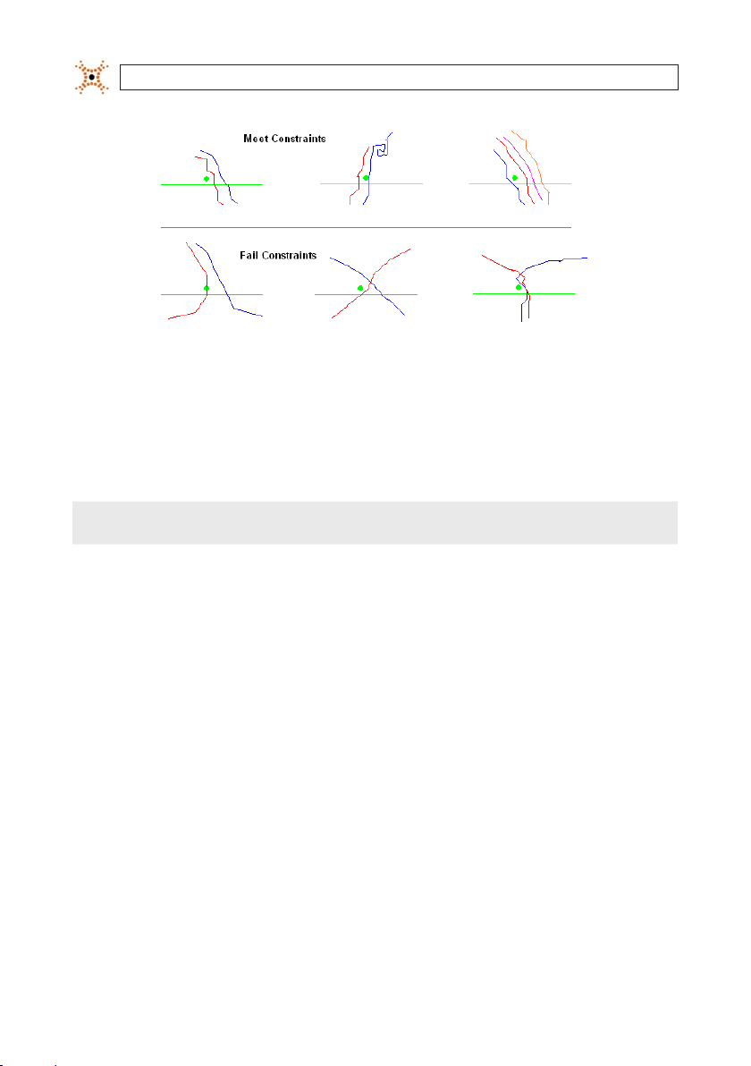
SECTION 5: CONFIGURE COUNTING LINES
Shopping Unit exa mples
5.5 Child Counting
When the Child Counting f eature is turned on, the zone will only count tracks that have eights below the Height Filter set on the
Calibration page. Any track with a height taller than the Height Filter will be excluded from the enter/exit counts.
NOTE
Occlusion issues occur mo re regularly due to the height and size of the t ypical child. This may decrease the DIGIOP ® 3D
camera tracking abili ty and therefore reduce counting accuracy.
5.6 Filtering counts based on velocity
The Velocity lter allows you to exclude fast moving track s from the enter/exit counts. This functionalit y is particularly usef ul in
corner shops within malls. These t ypes of stores typically have a high volume of “cut-through” trac. These track s are shoppers
who are taking the shortest distance to their destination and who are not actually shopping the corner store therefore they should
not be included in the enter/exit counts.
5.7 Exclusion Lines
Exclusion lines can be created to help dis card employee tracks or other activit y in areas where you do not want to count. If a track
touches any por tion of an exclusion line, the track is e xcluded from future count s. If the person crosse s enter, e xit, or pass lines prior
to crossing or touching an exclusion line, the person will be counte d.
5.8 Multiple Count Zone Support
The DIGIOP® 3D camera supports multiple count zones within a single dev ice. This allows you to count enters, exits, and passes for
multiple areas of interest. Consider, for example, an implementation in a mall environment where you have a DIGIO P® 3D camera
mounted so that the coverage area includes b oth the entrance and a three meter area outside the front of the store. You can create
44
www.digiop.com
Page 53

SECTION 5: CONFIGURE COUNTING LINES
two zones, one t hat contains enter and exit lines for the s tore, and one that contains a pass line perpendicular to the count line s for
counting people who pass by the store.
NOTE
Each zone can func tion as either an Enter/Exit zone or a Pass zone. You can not have a pass li ne in the same zone as Enter
and Exit line s. Note: Up to six zones (queuing, service, counting , or detection) can be added to each DIGIO P® 3D camera.
All zones func tion independently of one another. For example, if a device covers t wo separate doors, you can create one zone for
door 1 and one zone for door 2. You will then click on the name f or zone 1 and draw counting lines, then click on zone 2 and draw
the counting lines for that zone. The device will report sep arate enter and exit counts for each door.
If you want to obtain the sum of enters and exit s for both doors, you can create a single zone and draw a set of enter and exit lines
for door one and a set of enter and exit line s for door two. Since both sets of lines are part of t he same zone, the device will sum all
entrances through door one and door t wo into a single “Enter” count. The same is true with “Exit” counts.
5.9 Naming Reporting Zones
When you congure the DIGIOP® 3D camera, you should also give the report zone a desc riptive name so that you know what area
is being monitore d. For example, if you have two devices counting entrances at t he front and back doors you may want to name
the zone tracking entrances through the front doo r “Front Door Entrances” and the zone counting entrances t hrough the back door
“Back Door Entrances.” Complete the follow ing steps to name a reporting zone:
1. Access the conguration application from your web browser.
2. Click the Counting tab. The Counting page appear s.
3. Double -click the Name eld of the zone you want to rename in the zone list toward the bottom of the page.
4. Type a new zone name.
5. Click Save.
5.10 Drawing Enter, Exit, and Exclusion lines
Use the following guidelines when creating enter and exit lines:
• Do not place lines on or near the edge of the image space shown on the scre en. The DIGIOP® 3D camera must track a person fo r
a minimum distance be fore it can count them.
• Lines should be drawn on the oor bas ed on a customer’s foot position.
• Lines should be positioned such that the DIGIOP® 3D c amera sees the entire person (top of the head).
• Place the enter line at the point w here you consider an individual to have entered the location.
45DIGIOP® 3D Camera User Manual
Page 54

SECTION 5: CONFIGURE COUNTING LINES
• Place the exit line at the point where you consider an individual to have exi ted the location.
• Do not use pass line s in the same zone with enter or exit lines.
• Make sure that the direc tional circle on the enter or exit line is turned in the direction of t rac ow.
To draw counting lines:
1. Access the DIGIOP® 3D camera Conguration applicat ion.
2. Click the Counting tab to view the current counting conguration.
Conguration Application – Counti ng tab
3. Right click in the zone list. A pop -up menu appears.
46
www.digiop.com
Zone List box
Page 55

SECTION 5: CONFIGURE COUNTING LINES
4. Selec t New from the pop-up menu. A new zone appears and t he zone name is active for editing.
Zone List box with New Zone
5. Type the name for t he new zone in the Name eld.
Zone List box with New Zone renamed
6. (Optional) If you need to map zones bac k to specic IDs within your company, click the E xternal ID eld and typ e the ID for
the zone. This ID will be sent with the XML pac ket so that you can map the count data based on your specic ne eds.
7. Click the Enter button in the button bar and draw an enter line on the lef t image.
The DIGIOP® 3D cam era has a Minimum Track Distance setting that requi res the total track distance to be at least 90 cm
!
WARNING
(~36 in) for the m to be counted by any counting lines. This all ows the camera to prevent short tracks fro m being counted.
Tracks must move at least 90 cm in to tal distance, not 90 cm prior to crossing a count lin e.
DIGIOP® recommen ds this setting remain at 90 cm fo r all applications. For info rmation on changing th is setting refer to the
Advance Options sec tion of this manual.
47DIGIOP® 3D Camera User Manual
Page 56

SECTION 5: CONFIGURE COUNTING LINES
Button Bar
The enter line should be drawn with the directional circle in t he direction of the trac ow t hat you want to count. You can rotate
the Enter and Ex it lines in any direction to count trac ows in various environments.
Enter (green) and Exit (blue) lines with trac ow indicator s
!
WARNING
If you draw two exit (or enter) line s in such a way that they count trac ows in opp osite directions, the system will sum
the enters and exit s and report the total trac count as eithe r an exit or enter count.
8. Click the E xit button in the but ton bar and draw an exit line on the image.
48
www.digiop.com
Page 57

SECTION 5: CONFIGURE COUNTING LINES
NOTE
Acceptable use of ente r/exit lines:
Unacceptable use of lines
You can draw multiple enter, exit, and excl usion lines within a single came ra. When drawing multiple lines around a si ngle
entrance way, they should overlap sl ightly. Identical line types direc tly in front of or behind one a nother have no eect on the
resulting counts an d should not be drawn.
If you need to move the lin e 1 pixel at a time, click the line to select i t, then use the arrow keys on your keyboard to move th e
line.
Lines are in between secu rity cameras
The lines are too long and two enter lines
were used so both enters and exits will be
recorded as entrances.
The lines are too long and there are two enter
lines overlapping the same area so enters are
double counted.
49DIGIOP® 3D Camera User Manual
Page 58

SECTION 5: CONFIGURE COUNTING LINES
9. Click the E xclusion button to draw any e xclusion lines. Exclusion lines can be used to eliminate the counting of people who
enter certain areas of the camera coverage area. After a per son crosses an exclusion line their future count s are ignored.
10. To ne tune line placement, click and drag the line to t he desired location. Then sele ct the line and use the square handles on
either size to resize t he line.
NOTE
If you need to move the lin e 1 pixel at a time, click the line to select i t, then use the arrow keys on your keyboard to move th e
line.
11. Click Save to permanently save the settings to the camera, or clic k Preview to save the sett ings until the camera is reset or
unplugged.
5.11 Adding Filter Zones to Count Zones
Filter zones help you to eliminate false counts f rom employees, customers, and doors. If you are installing the DIGIOP® 3D camera in
an environment where the following trac patterns occur, you should congure a lter zone:
• Cross Trac – Customers cross the counting lines multiple times while they are shopping.
• Employee Trac – Employees cross counting lines to open the door for customers.
• Door Swing – The doors swing to the inter ior of the store and cross counting line s.
5.11.1 How does a Filter Zone work?
For Enter counts, t he Filter Zone denes the area where tracks star t.
For Exit counts, the Filter Zone denes the area where t racks end.
Filter zone is drawn all the way up the exit line so that tracks
do not get droppe d because they are in between the end of
the lter zone and count line.
50
Filter zone ex tends all the way to the edge of the eld of view
to make sure all tracks leaving the store end in the lter zone.
Counting Zones with a Filter Zone (good conguration)
www.digiop.com
Page 59

Example s:
SECTION 5: CONFIGURE COUNTING LINES
Filter zone is too small. Tracks entering the store c an start
outside of the lter zone and track s leaving the store can end
before making i t to the lter zone.
Both of the trac ks in this sample would not be counted.
Counting Zones with a Filter Zone (bad conguration)
No Enter or Exit Count recorded because the track did no t
start in the lter zone.
No Enter or Exit Count recorded because the track did no t
end in the lter zone.
51DIGIOP® 3D Camera User Manual
Page 60

SECTION 5: CONFIGURE COUNTING LINES
One Enter Count recorded because the track started in the
lter zone and crossed the Enter line.
One Exit Count recorded because the track ende d in the lter
zone after crossing the ex it line.
5.11.2 Using Filter Zones in cameras mounted outside the store
In some installations, the DIGIOP® 3D c amera device might be mounted out side a store. To use lters zones for thes e installations,
set the zone t ype as an External Entrance. The External Entrance se tting reverses the lter zone logic so that trac ks that end in a
lter zone are counted as Entrances, and trac ks that start in the lter zone are counted as Ex its. When this option is used, t he lter
zone should be placed on t he other side of the counting lines so that t racks entering the store will cross the count lines, then enter
into the lter zone.
5.11.3 Adding a Filter Zone to a Count Zone
If you are adding a lter zone to a count zone, you should rs t create the enter and exit lines. Complete the following steps to add a
lter zone to a count zone:
1. Access the Counting tab.
2. Right-click on the Zone name in the list. A pop-up menu ap pears.
52
www.digiop.com
Page 61

SECTION 5: CONFIGURE COUNTING LINES
Counting tab with pop-up me nu
3. Selec t Filter. An orange lter zone appears in the image space.
4. Place your mous e cursor in the middle of the orange lter zone and click and drag to move i t to the general area where you
want to place your lter zone.
NOTE
If the DIGIOP® 3D ca mera is mounted outside the store, the lter zone sh ould be placed in between the cou nting lines and
the door.
5. Click the or ange lter zone. Several small orange square s appear, these squares are handles that allow you to resi ze the lter
zone to t your environment.
6. Click and drag each orange handle to reshape the zone to your spe cications. Since Filter zones are used to lter out fals e
counts from browsing trac within a store, place the lter zone in the entrance corridor and ex tend it to the exterior side of
the store. (See the following sample.)
NOTE
If the camera is mounted out side the store, the lter zone should be pl aced in between the counting line s and the door.
53DIGIOP® 3D Camera User Manual
Page 62

SECTION 5: CONFIGURE COUNTING LINES
Sample Filter Zone
7. If the DIGIOP® 3D camera is mounted outside of t he store, complete steps 8-11, otherwise click Save to save your change s
and skip steps 8-11.
8. Right-click the zone name and select Congure. The Counting Cong Parameter s dialog box appears.
Counting Cong Parameters dialog box
9. Selec t the Enable check box in the E xternal Entrance group.
10. Click OK. The Counting Cong Parameters dialog box closes.
11. Click Save to save your changes.
54
www.digiop.com
Page 63

SECTION 5: CONFIGURE COUNTING LINES
5.11.4 Filtering Tracks based on Velocity
Complete the following steps to exclude t racks that are traveling faster than a certain sp eed:
1. Access the Counting page.
2. Selec t the Velocity check b ox in the upper right corner.
3. Enter a value ( cm/se c) in the Velocity eld. A normal walking speed is between 90 – 140 cm/sec.
4. Click Save. The CAMERA will now exclude all track s that travel through the eld of view at a velocity that is higher than the
threshold.
5.12 Enabling Child Counting
Complete the following steps to set count lines to only count track s that are typically children (those that are below the height lter
set on the Calibration page):
1. Access the Counting page.
2. Right-click the zone name from the zone list. The right-click menu appears.
3. Selec t Congure. The Counting Cong Parameters dialog box appears.
4. Selec t the Enable box in the Child Counting group.
5. Click OK. The Counting Cong Parameters dialog box closes.
6. Click Save. The changes are saved an d the zone is set to only count tracks t hat are below the Height Filter sett ing on the
Calibration page.
NOTE
This feature requires purchase o f Advanced Firmware. .
5.13 Enabling Shopping Unit Counting
Complete the following steps to enable shopping unit counting:
55DIGIOP® 3D Camera User Manual
Page 64

SECTION 5: CONFIGURE COUNTING LINES
NOTE
See “Counting Multi ple Tracks as Shoppi ng Units” in this manual for mo re information on Shoppin g Unit functionalit y.
1. Access the Counting page.
2. Right-click the zone name from the zone list. The right-click menu appears.
3. Selec t Congure. The Counting Cong Parameters dialog box appears
4. Selec t Enable in the Shopping Unit group.
5. Enter the ma ximum time dierence, in milliseconds, allowed between the start times of track s to be counted as a shopping
unit in the Time Di erence eld. If two or more track s start at points in time t hat are greater than this threshold, they are not
counted as a shopping unit.
6. Type the maximum distance, in centimeters, allowed bet ween the starting points of track s to be counted as a shopping unit
in the Start Track Max Distance eld. If the s tart points of two or more tracks are further apart than this threshold, they are
not counted as a shopping unit.
7. Enter the ma ximum distance, in centimeters, that tracks are allowed to drift apar t after they are initially considered a
shopping unit in the Track Max Distance eld. If tracks separate, they will not be counte d as a shopping unit.
8. Click OK. The Counting Cong Parameters dialog box closes.
9. Click Save.
5.14 Verifying Count Line, Filter Placement, and Calibration
Viewing various trac maps from the counting page can help you tune the placement of counting lines base d on the actual ow
of trac. To use this feat ure, clear all existing trac maps and le t the camera run for 4 to 6 hours to allow ade quate trac to ow
through the tracking area. Then, use the maps to adjust your counting lines and lter zones.
NOTE
5.14.1 Types of Maps
This sect ion describes the variou s types of maps available in the DIGIOP® 3D camera.
56
www.digiop.com
All map data is cleared when t he camera is rebooted or the Clear Maps butto n is pressed.
It is important to cl ear the maps and allow the camera to run fo r 4-6 hours before adj usting counting and lter zones.
Viewing multiple d ays of data in the maps is not recommended beca use the high number of tracks repor ted may make the
maps dicult to read.
Page 65

SECTION 5: CONFIGURE COUNTING LINES
Map Name Desc ription
3-D Trackin g Shows t he real time view o f objects t hat are current ly being tracke d.
Trac Map
Start Sto p Map S hows the star t (green) and end (red) p oints of all tra cks. This map i s useful for p ositioning l ter zones.
Height Map
Dwell Map
Shows a colo r coded heat map of a ll tracks sinc e the last rese t. The brighter t he colors, the h igher the tra c volume. This map is u seful
for posi tioning zones .
Shows a colo r coded heat map of a ll track height s since the last r eset. The bri ghter the color, the t aller the objec t. This map is us eful for
verif ying correc t calibratio n settings .
Shows a colo r coded heat map th at displays the d well points of all t racks since t he last reset . Dwell points r epresent whe re people stop
and stan d in the same loca tion. This map is p rimarily use d for queueing an d service app lications.
5.14.2 Verifying Count Line placement
Complete the following steps to verif y the count line placement:
1. Access the Counting tab and click Clear Map s.
2. Allow the DIGIOP® 3D camera to run f or 4-6 hours depending on trac volume.
3. Access the Counting tab and select Trac Map from the drop-down box. The Trac Map appears in the right image space.
Counting page with Trac map
4. Verif y that the count lines are positioned in such a way that all trac has to cross the lines.
57DIGIOP® 3D Camera User Manual
Page 66

SECTION 5: CONFIGURE COUNTING LINES
5. Click Save.
5.14.3 Verifying Filter Zone placement
You should use the Start Stop Map to verify the placement of Filter zones. Filter zones allow you to dene the area that track s must
start or end in to be counted as an enter or an e xit. The Start Stop Map allows you to se e exactly where track s start and end so that
you can place the lter in the correct location.
Complete the following steps to verif y Filter Zone placement:
1. Clear the maps by resetting the camera, then r un the camera for 4-6 hours.
2. Access the Counting tab and selec t Start Stop Map from the drop -down box. The Start Stop Map appears in the right image
space.
Counting page with Start Stop map
3. Verif y that all starts and stops are included in the de sired lter zone and that the enter/exit lines have not been drawn too
close to the start and stop p oints.
4. Click Save.
58
www.digiop.com
Page 67

SECTION 5: CONFIGURE COUNTING LINES
5.14.4 Verifying calibration settings
Perform a nal calibration che ck using the Height Map while you are conguring your count and lter zones. Complete the
following steps to verify the calibration:
1. Access the Counting page and select Height Map from the drop-down.
Counting tab with Height map
2. Verif y that the colors through the main tracking area are the same or similar color of yellow. The main color change s should
be toward the edge s of the image space. If you notice that the color changes appear throughout the image space, or t hat they
happen unevenly from the top to bottom of the image space, you should check the Y rotat ion on the calibration page.
If you notice that color changes happen unevenly from the lef t to the right of the image space, check t he X rotation on the
calibration page.
The images below show what the height map look s like when various calibration problems occur:
59DIGIOP® 3D Camera User Manual
Page 68

SECTION 5: CONFIGURE COUNTING LINES
Decrease the Height value on the Cali bration page. Increase the He ight value on the Calibration page.
Decrease the X Rotation value on the Calib ration page. Increase the X Rotation value on the Calibrati on page.
Decrease the Y Rotation value on the Calib ration page. Increase the Y Rotation value on the Calibration p age.
60
www.digiop.com
Page 69

SECTION 5: CONFIGURE COUNTING LINES
5.15 Adding additional Counting Zones
If the DIGIOP® 3D camera covers multiple entrances and exits, you can create multiple zones to separately count at each entrance
and exit. For example, if you have a single camera that covers an entrance and the sidewalk ou tside, you can create one zone
to count customer entrances and one zone to count passes in front of the store entrance. Complete the following steps to add
additional zones to the device:
1. Access the conguration application from your web browser.
2. Click the Counting tab. The Counting page appear s.
3. Right click in the zone list. A pop -up menu appears.
Zone List box
4. Selec t New from the pop-up menu. A new zone appears and t he zone name is active for editing.
Zone List Box with New Zone
5. Enter the name for the new zone in the Name eld.
61DIGIOP® 3D Camera User Manual
Page 70

SECTION 5: CONFIGURE COUNTING LINES
Zone List Box with New Zone renamed
6. Complete the normal process f or drawing count lines.
5.16 Deleting Enter, Exit, Exclusion Lines, and Filter Zones
Complete the following steps if you want to delete a count line that is attached to a spec ic zone:
1. Access the Counting tab.
2. Verif y that the Display All check box is not selec ted.
3. Click the reporting zone to which the line or lter zone is attached. All lines and lter zones for the selected zone appear.
4. Click the line or lter zone to be deleted. Square handles appear on each end of the line.
5. Press the Delete key to remove the line.
NOTE
The Backspace key do es not delete count lines. Use only th e Delete key.
6. Click Save to s ave your changes.
5.17 Deleting Zones and All Attached Count Lines
Complete the following steps if you want to delete a reporting zone and all count lines that are attached to i t:
1. Access the Counting tab.
2. Verif y that the Display All check box is not selecte d.
3. Click the name of the reporting zone to be removed. The selected zone is highlighted.
62
www.digiop.com
Page 71

SECTION 5: CONFIGURE COUNTING LINES
4. Right-click on the name of the repor ting zone to be removed. A pop-up menu appears.
5. Selec t Delete. The zone and all attached lines are delete d.
6. Click Save to s ave your changes.
5.18 Conguring Digital Input/Output
The D3D-2500 camera can s end digital output to and receive inpu ts from the GPIO port . The GPIO port provides thre e input/output
streams in any combination. Each input/output must have a zone created on the counting page prior to conguring the options on
the Data Deliver y page.
5.18.1 Digital Output
Complete the following steps to congure digital output f or a count zone:
1. Create count line s as described in “Enter and E xit Lines”.
2. Click Basic Settings->Data Delivery.
3. Click to ex pand the Alert Digital Out put section of the scre en.
63DIGIOP® 3D Camera User Manual
Page 72

SECTION 5: CONFIGURE COUNTING LINES
4. Click the Digital I/O drop -down arrow and select O utput.
5. Click the Pu lse Style drop-down and select either NPN or PNP for the t ype of pulse to send.
6. Enter the Pu lse Length in milliseconds. This value sets the duration of the pulse t hat is sent after a count line is crosse d.
7. Type the After-Pulse Delay in milliseconds. This value sets the minimum time in between successive pulse aler ts.
8. Click the Zo ne ID drop-down and selec t the zone containing the count lines that are used to trigger puls e events.
9. Selec t Enters, Exits, or bot h check boxes to specif y whether pulse outputs are sent for enter and/or exit line events.
10. Click Save.
11. Connect the ex ternal device to the GPIO port.
5.18.2 Digital Input
The D3D-2500 camera accept s digital pulses from an ex ternal device through the GPIO por t. The camera receives the pulse and can
increment the enter and/or exit counts each time a pulse is received. Complete the following steps to setup digital input:
1. From the Counting tab, right-click in the zone list and selec t new. A new zone appears in the list. Do not c reate count or pass
lines for this zone.
2. Click Save.
3. Click Basic Settings->Data Delivery.
4. Click to ex pand the Alert Digit al Output section.
64
www.digiop.com
Page 73

SECTION 5: CONFIGURE COUNTING LINES
5. Click the Digital I/O drop -down arrow and select Input.
6. Click the Pu lse Style drop-down and select either NPN or PNP for the t ype of pulse to receive.
7. Enter the Puls e Length in milliseconds. This value sets the duration of the pulse that is received.
NOTE
Pulse length must be be tween 10 ms and 3000 ms.
8. Enter the Af ter-Pulse Delay in milliseconds. This value sets the minimum time in bet ween successive pulse alerts.
9. Click the Zo ne ID drop-down and selec t the zone to which pulse counts are assigned.
10. Select Enters, E xits, or both check boxes to specif y which counter increments when an input pulse is received.
11. Click Save.
12. Connect the ex ternal input to the GPIO port as described in Section 1:
65DIGIOP® 3D Camera User Manual
Page 74

SECTION 6: CONFIGURING QUEUING APPLICATIONS
SECTION 6
Conguring Queuing Applications
This sect ion describes how to congure the D3D-2500 to monitor queue ac tivity. Once congured, the D3D-2500 sends queue
data (number in queue, queue op en/closed stat s, etc.) to DIGIOP ELEMENTS™ software or to a data delivery IP addres s. Queue data
provides ver y useful statistic s, especially when associate d with information from other sources. Data is sent in XML format.
6.1 Queuing overview
The queuing feature uses three congurable zones:
• Queue count area: This (green and pink) zone is used to dene the area that the camera uses to calculate the queue length
and queue wait time me trics.
• Head zone: This (blue) zone is used to determine when a queue is open or closed. If a per son stands in the head zone for a
period of time e xceeding the open time setting (usually 10 seconds) the queue is considered to be open. If the head zone stays
unoccupied for a period of time exceeding the clos ed time setting (usually 30 seconds) the queue is considered clo sed.
• Tail zone: This (orange) zone is used to lter tracks that are used for wait t ime calculations.
The Queue count and Head zones have parameter s that can be accessed by clicking the Advanced button from the Queuing tab.
When generating queue metrics, the D3D-2500 only considers those track s that pass the counting constraints (minimum height,
maximum height, and c art lter) and a set of behavioral cons traints (minimum time in zone, proximity to another person in queue,
etc.). The D3D-2500 only generates queue metrics when the queue is open.
6.1.1 Head Zone functionality
The head zone allows the s ystem to determine when a queue is op en. When a person stands inside t he head zone for a designated
period of time, usually 10 seconds, the queue s tate is marked as open and the D3D-2500 begins counting anyone who enter s the
queue count area and mee ts the constraints for counting (describe d later). When the queue is in a closed state, no queue met rics are
counted.
6.1.2 Head Zone constraints
Open Time: S ets the minimum time, in seconds, that p erson must stand inside the head zone before the queue is considered
“open.” After this threshold is e xceeded, all tracks that meet the queue constraints and enter the queue are included in t he queue
length metric.
Closed Time: Sets the minimum time that the head zone must stay empt y before the D3D-2500 will close the queue an d stop
counting track s entering the queue.
66
www.digiop.com
Page 75

SECTION 6: CONFIGURING QUEUING APPLICATIONS
6.1.3 Queue Count Area functionality
After the head zone has been occupied by a person for the required period of time, the camera will begin to count all t racks that
pass a set of queue constraints. To be included in the queue count, a track must p ass the following constraint s:
• Must pass counting constraint s (minimum height, maximum height, and cart lter).
• Must be within t he queue count area (green and pink zone).
• Must be within t he queue count area for longer than the queue minimum time.
• The rst per son in the queue count area must be within a specied distance from people in the head zone (Track Dist eld o n
the advanced pop -up) for a specied amount of time ( Track Time on the advanced pop-up).
• Each additional person in the queue must be within a specied distance (Track Dist from the advanced pop-up) from either
the people in the head zone or any other people currently included in the queue. All pe ople counted in the queue must remain
within the Track Distance threshold for a sp ecied amount of time (Track Time f rom the advanced pop-up) before t hey are
considered to be part of the queue.
• For queue wait times to be counted, the track must also start out side of the queue count area or within the queue tail zone.
6.1.4 Queue Count Area constraints
Min time: Set s the minimum time that a person mus t remain in the queue count area before they are eligible to be counted in the
queue length.
Track Dist: Denes the maximum dis tance, in centimeters, that a person entering the queue must be from a person already in
the queue in order to be counted. If the distance between people in the queue meets he dis tance threshold for greater than the
time threshold ( Trac k Time) the track is considered in the queue. The track must also meet the counting constraint s in order to be
counted, other wise the track is not included in the queue length calculation.
Queue Minimum Track Distance
67DIGIOP® 3D Camera User Manual
Page 76

SECTION 6: CONFIGURING QUEUING APPLICATIONS
Track Time: The minimum time that a person in the queue must be within the Track Dist of another person cur rently in the queue
count area or head zone bef ore they will be added to the queue leng th.
Merge Time: The minimum time that a per son, who entered the queue zone, can ex it the queue zone, and then re-enter, and have
their wait time merged into the queue wait time.
Merge time example track
NOTE
The person must stay wi thin the camera eld-of-view for th e wait time to be merged. If the person e xits the eld-of-view,
then reenters the queue zo ne, the wait times is treated as two wait times i nstead of being merged into one.
6.1.5 Queue Tail Area
By default, the camera does not calculate wait time for a person if their track star ts inside the queue count area. In some
congurations a queue may extend to the edge of the D3D-2500 coverage area. In these situations, it is impossible for some tracks
to start outside of the zone b ecause the zone extends to (or near) the edge of the coverage area.
Tail areas are for conguring a zone of the coverage area within which, if a track starts, the wait time is recorde d.
6.1.6 Queue Exclusion area
Dening a Queue E xclusion area allows you to exclude wait time s and queue lengths for track s that enter the exclusion area. This
functionality is commonly used in customer service areas w here employees often move from behind a counter or ser vice desk to
the queue to assis t the customer. The employee’s wait time should not be counted in the wait time metrics, so the exclusion zone is
drawn. If any track enters an exclusion area before or af ter entering a queue area, the wait time for that track is excluded from the
metrics.
68
www.digiop.com
Page 77

SECTION 6: CONFIGURING QUEUING APPLICATIONS
Sample Queue Layout with E xclusion Are
6.1.7 About the Queue Length metric
The D3D-2500 calculates the queue length met ric based on individuals who pas sed counting constraints and queue zone
constraint s. The D3D-2500 sends data packets that contain the Average Queue Leng th, Max Queue Length, Minimum Queue
Length, and Number of Seconds Open. The D3D-2500 au tomatically calculates these metrics at the ag gregation level you selected
on the Data Deliver y tab. In order for a track to be counted in the queue length, it :
• Must be in a queue that is in the Open state.
• Must pass counting constraint s (minimum height, maximum height, and cart lter).
• Must be within t he queue count area (green and pink zone).
• Must be within t he queue count area for longer than the queue minimum time.
• The rst per son in the queue count area must be within a specied distance from people in the head zone (Track Dist. eld on
the advanced pop -up) for a specied amount of time ( Trac k Time on the advanced pop-up).
• Each additional person in the queue must be within a specied distance (Track Dist. from the advanced pop-up) from either
the people in the head zone or any other people currently included in the queue. All pe ople counted in the queue must remain
within the Track Distance threshold for a sp ecied amount of time (Track Time f rom the advanced pop-up) before t hey are
considered to be part of the queue.
For details on the se constraints, see Head Zone Constraints and Queue Count Area Constrai nts.
The following diagrams show examples of how the Queue zones calculate queue lengths in various scenario s.
69DIGIOP® 3D Camera User Manual
Page 78

SECTION 6: CONFIGURING QUEUING APPLICATIONS
Queue Length Repor ted as Zero Queue Length Repor ted as 1
The pers on has passed t he counting con straints an d is inside the que ue head,
which mean s the queue is ope n. However, the per son is not inside t he queue
count area, s o they are not incl uded in the queu e length metr ic at this time.
Queue Length Repor ted as 3 Queue Length Reported as Zero
The rs t person in the qu eue is standin g inside the queu e head but outs ide of
the queue c ount area becau se they are at the s ervice point . The last per son is
not consid ered to be a par t of the queue bec ause they are ou tside of the tr ack
distanc e threshold.
The pers on has passed t he counting con straints an d is inside the que ue head
area, which m eans the queue is o pen (assuming th e person in the c urrent
positi on was there for a t ime greater than t he Open Time).
The pers on is also inside t he queue count are a which means the y are being
counted as p art of the que ue (assume that the p erson has pas sed the counting const raints and wa s in the current lo cation for a ti me greater than th e
queue zone M inimum Time).
Even thou gh all tracks ar e within the tr ack distance th reshold, ther e is no one
in the queu e head, which means t hat no one is bein g served at the s ervice
point and t he queue is close d.
70
www.digiop.com
Page 79

SECTION 6: CONFIGURING QUEUING APPLICATIONS
6.1.8 About the Queue Wait Time Metric
The queue wait time metric retur ns the length of time between the time a person enter the queue count area and the time they
cross the pink line on t he queue count area. Note that not all tracks that enter the queue, even those included in the queue length
metric, will have a queue wait time. For a tr ack to have a queue wait time, it must:
• Pass all counting constraints (minimum height, ma ximum height, and cart lter).
• Start out side of the queue count area or within the tail zone.
• Be tracked cont inuously through the queue.
• Cross the pink queue exit line on the queue count area.
If a track meets all of these conditions, its wait time is sent in a metric packet at the aggregation level you selected in the Data
Delivery tab. O therwise, the wait time is discarded. The following drawings show how t he D3D-2500 handles various queue wait
time scenarios:
Queue wait time examp les
In the foll owing diagrams , the circles rep resent the Track D istance area.
In the repr esentation a bove, the indivi dual has a valid wai t time becaus e the
track s tarted out side of the count a rea. If the Debug c heck box is sele cted on
the Queue p age, the pers on has a track ID, and w ait time displaye d next to
them. Whe n the track cro sses the pink lin e, the wait time is nalized and sent
in a metri c packet. Then t he track ID and wa it time change to a g reen dot.
Althoug h all tracks are w ithin the tra ck distance th reshold, ther e is no one in
the queue h ead, meaning that t he queue is clos ed and all track s within the
queue coun t area are ignored . If the Debug ch eck box is selec ted, the disp lay
will not show a ny indicator fo r these track s.
71DIGIOP® 3D Camera User Manual
Page 80

SECTION 6: CONFIGURING QUEUING APPLICATIONS
The pers on passed th e counting cons traints, st arted out side the queue co unt
area and cro ssed the pink qu eue exit line. T he track wait t ime was sent in a
metric p acket. If the D ebug check box i s selected o n the queue page, t he dot
changes f rom the green “ track ID, wait tim e” format to a gre en dot.
Assume t hat all individua ls in this exampl e passed the co unting const raints.
The rs t person sta rts outsi de of the queue cou nt area and continu es through
the pink qu eue exit, at whi ch point their wa it time is sent ou t in a metric
packet. I f the Debug che ck box is selec ted, a green dot i s displayed.
The seco nd and fourt h people star t outside t he queue count area , currently
have valid wai t times, and have n ot yet crosse d the pink queue ex it line. If
the Debu g check box is sel ected, the ID a nd wait time is dis played. The thir d
person s tarts in side the queue cou nt area, so the wai t time is not valid.
The last p erson is in the qu eue count area but i s not within the Trac k Distance
thresho ld of another per son in the queue .
72
www.digiop.com
Page 81

SECTION 6: CONFIGURING QUEUING APPLICATIONS
Queue wait time examp les - Tail zone
In the foll owing diagrams , the circles rep resent the Track D istance area.
Assume t hat all individua ls in this exampl e passed the co unting const raints.
The rs t person sta rts inside of t he queue count ar ea and does not have a
valid wait t ime because t racks that s tart in the zon e are ltered fr om the wait
time calc ulations. The s econd and four th person s start out side the queue
count area, c urrently have va lid wait times, an d have not yet cros sed over the
pink queue e xit line. The th ird and fth p ersons both s tart insid e the queue
count area s o the wait time is no t valid (yellow). This e xample shows th at a
method i s needed to inc lude tracks t hat start in side the queue co unt area but
still have c omplete track s; otherwi se, valid wait ti mes are discard ed. See the
example o n the right to se e how the queue tail z one is used to inc rease the
wait time s ample size.
Assume t hat all individua ls in this exampl e passed the co unting const raints.
The rs t person sta rts inside of t he queue count ar ea and also inside t he tail
zone, then c ontinues thro ugh the pink queu e exit. Bec ause the track s tarted
in the tail zo ne, which dene s a specic are a in which wait tim es can be
calculat ed even if the tr ack originate s in the zone, the wai t time is nalize d
and writ ten to a metric p acket. The se cond and four th persons s tart outs ide
the queue c ount area, curre ntly have valid wai t times, and did no t yet cross
the pink qu eue exit line. Th e third perso n starts in side the queue co unt area
so the wai t time is not valid. T he last perso n in the queue count a rea starte d
within b oth the queue cou nt and tail zones, a nd therefore t he track has a
valid wait t ime; the wait tim e is nalized when t he track cros ses the pink
exit line .
6.1.9 Sample Queue zone congurations
The following samples show how queue zone s are generally drawn for grocery/retail and s erpentine queue environments.
Grocer y and Retail Queues
73DIGIOP® 3D Camera User Manual
Page 82

SECTION 6: CONFIGURING QUEUING APPLICATIONS
Grocery and Re tail queues are typically drawn with the head zone (blue zone) covering a person checking out at the register, and
extending b ack to cover the queue area adjacent to the checkout conveyor belt. The queue count area (green and pink zone) is
drawn to overlap with t he head zone and extend back to where qu eues form for each checkout . The pink line should be positioned
so that people in t he queue cross it when they move to the service point. The Tail zone is created at the back of t he queue count area
to allow wait time calculat ions for tracks that start in the back of t he queue.
Serpentine Queue Congurati on
Serpentine queues are congured with the head zone (blue zone) drawn where the front of the queue forms. The head zone must
be drawn large enough to encompass the rs t 3 or 4 people in the queue. The queue count area (green and pink zone) is drawn over
the entire queue area and completely overlap the head zone. The pink line should be p ositioned at the queue exit s o that all people
exiting the queue will cross the pink line before moving to a teller.
6.1.10 Notes about drawing queues on a slow network
If you are using a slow net work connection to congure t he D3D-2500 you may nd that it is dicult to draw and move zones in
image space. If you have this problem, click Pause on t he Queueing page to stop the live vide o stream while you draw and position
your zones. Af ter drawing the zones, click Play to restart the live video stream and test your conguration.
6.2 Creating a new Queue zone
To create a new queue zone in the D3D-2500, do the f ollowing:
74
www.digiop.com
Page 83

SECTION 6: CONFIGURING QUEUING APPLICATIONS
NOTE
!
WARNING
The camera unit must be prop erly installed and calibrated prior to com pleting any of the steps in this secti on.
Up to six zones (queuing, ser vice, counting, or detection) can be added to ea ch D3D-2500.
Each D3D-2500 captures a maximum of 1900 sa mples per day across all queue an d service zones. If the number of wait /
service times exceeds 1900, d ata collection stops until the ne xt day. Contact DIGIOP® if you are col lecting queue or service
times in ex tremely high trac environments, such as a t conferences or trade shows.
1. Open the D3D-2500 conguration applic ation using your web browser.
2. Click Que uing. The Queuing tab appears.
3. Right click on the white space under t he table headings in the Queue group. A right-click menu appears with New as the only
option.
4. Click Ne w to create a new queue zone. A new row appear s in the table and a blue head zone and green and pink queue count
area appears in the video image.
75DIGIOP® 3D Camera User Manual
Page 84
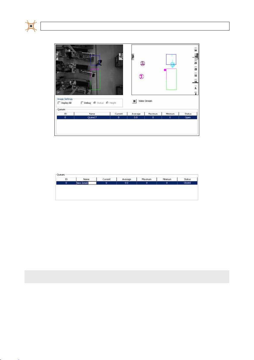
SECTION 6: CONFIGURING QUEUING APPLICATIONS
5. Double -click the Name eld for the new zone. A cursor appears in the Name eld.
6. Use the mouse to select the default zone name that was populated w hen you created the new zone.
7. In the Name eld, enter the new name for the Zone (Queue 1, Queue Lane 10, etc.).
8. Move the mou se cursor anywhere out side the name eld and left-click (or press Enter) to close edit mode.
9. Click anywhere in the newly add ed queue row to display the queue zone in the image.
10. Place your mouse cursor in the middle of the blue queue head zone, then click and drag to move it to the general area where
you want to place a head zone.
NOTE
To move the zone one pixel at a ti me, click the line to select it, then use the ar row keys on your keyboard to move the line.
11. Click the blue head zone. Several small blue boxes will appear. These boxes are handles that allow you to resize the head zone
to t your environment.
76
www.digiop.com
Page 85

SECTION 6: CONFIGURING QUEUING APPLICATIONS
12. Click and drag each blue handle to reshape the zone to your nee ds. Keep the following things in mind when you draw the
head zone:
— In banking, the head zone should encompass the front of the queue and the rst 3 or 4 pe ople in the queue.
— In grocery/retail, the head zone should encompass the person cur rently being served and the entire waiting area
immediately adjacent to the conveyor belt.
— Do not place or move head zones so that a portion of the zone is out side of the viewable image area in the applic ation.
— Draw the zones based on the locat ion on the oor where you want your queue. The D3D-2500 uses foot position to
determine an individual’s location in the image space.
13. Place the mouse cursor in t he middle of the green and pink queue count zone and click and drag to move it to the area where
you want to place your queue count area.
14. Click the green and pink queue count zone. Several small green squares appear, these boxes are handles that allow you to
resize the queue count zone to t your environment .
15. Click and drag each green handle to re shape the zone to your specications. Keep the following things in mind when you
draw the queue count area:
— The green zone mus t cover as much of the queuing area as possible and can overlap the blue zone if ne cessary.
— For queue wait times to be calculated, tracks must start outside of the queue count area. Do not draw your queu e count
area so large that it is impossible for trac ks to start outsid e of the zone. If a zone is close to the edge, make sure to place
the tail zone appropriately.
— Do not place or move queue count zones in such a way that a portion of the zone is outside of the viewable image area
in the application.
— Draw zones base d on the location on the oor where you want the queue. The D3D-2500 uses foot position to
determine the location of a pers on in the image space.
77DIGIOP® 3D Camera User Manual
Page 86

SECTION 6: CONFIGURING QUEUING APPLICATIONS
16. Click Save to save your conguration.
17. Repeat steps 1-15 with each additional queu e zone that is covered by the D3D-2500 camera.
18. Continue to “Adding a Queue Tail Zone” in the next se ction.
Note: A total of up to 6 zones of any t ype (counting, queuing, service, and dete ction) can be created in each D3D-2500 camera.
NOTE
Up to 6 zones of any typ e (counting, queui ng, service, and detection) can be created in each D3D-2500 unit.
6.2.1 Adding a Queue Tail zone
To add a queue tail zone to a queue.
1. Selec t a Queue from the Queues group on the Queuing tab of a D3D-2500 c amera.
2. Right click on the name of the queue where you want to add a tail. A pop -up menu appears.
78
www.digiop.com
Page 87

SECTION 6: CONFIGURING QUEUING APPLICATIONS
3. Selec t Tail. An orange box appear s in the left view window.
4. Click the box to move it to the appropriate area. Place the tail zone at the back of the queue count area where it overlaps
several feet of the queue count area.
NOTE
To move the zone 1 pixel at a time, cli ck the line to select it, then use the arrow keys o n your keyboard to move the line.
5. Selec t the orange box and click and drag the orange handles to resize the box as neede d.
6. Click Save to s ave your changes.
7. Continue to “Creating a Queue Exclusion Area” in the nex t section.
6.2.2 Creating a Queue Exclusion Area
The queue exclusion area is used to exclude employee wait time s. See “Queue Exclusion Area” on for mo re information. To create
a Queue Exclusion area:
1. Right-click a Queue from the Queuing tab, Queues group.
2. Selec t Exclude from the pop-up menu. A red E xclusion area appears on the scre en.
3. Click and drag the box to move it to the be st location.
4. Selec t the red box and click and drag the red handles to resize the box as needed.
5. Click Save to s ave your changes.
6. Continue to “S etting Advanced Options for Queues” in the ne xt section.
6.2.3 Setting Advanced Options for queues
The D3D-2500 has several cu stomizable parameters that determine how the queue should func tion in your environment. See
“Queuing Overview ” for more information. To access the Advance d Settings pop-up:
1. Open the D3D-2500 conguration applic ation using a web browser.
2. Click the Queuing tab.
79DIGIOP® 3D Camera User Manual
Page 88

SECTION 6: CONFIGURING QUEUING APPLICATIONS
3. Click the Advanced but ton in the lower right corner of the window. The Advanced sett ings pop-up appears.
Field Descr iption
Open Tim e Sets the minimum t ime that perso n must stand in side the head zone ( blue zone) befor e the queue count a rea is considere d to be
Closed T ime Set s the minimum tim e that the head zon e must stay empt y before th e queue zone will cl ose and stop coun ting track s entering the
Min Time Sets the mi nimum time that a p erson must re main in the queue co unt area or serv ice area before t hey can be count ed in the queue
Merge Tim e Th e minimum time th at a person, who ha s entered a zone, c an exit the zone a nd then re-en ter and have their wa it time merged i nto
Track Dist The maximum dis tance that a per son entering t he queue must be f rom a person a lready in the queu e to be counted. Se e “Queue
Track Time Th e minimum time tha t a person in the q ueue must be wit hin the Track Dist o f another pers on currently i n the queue count ar ea or
Filter Ti me The minimum t ime for which a tr ack must mee t the height and sha pe constrain ts to be counted i n the queue metr ics. DIGIOP ®
Discard F ront Entry Discards all qu eue metric s for tracks t hat cross the pi nk exit line pri or to appearing in t he queue. For ex ample, in a self- checkout
open. Af ter this thres hold is exceed ed, all track s that meet the qu eue constra ints and enter th e queue count area ar e included in the
queue leng th metric. D efault: 5 se conds.
queue coun t area. Default : 30 seconds.
length or s ervice time . For queues, tr acks must me et Track Dist and Trac k Time thresho lds. Defaul t: 5 seconds (queu e)
the queue w ait time or ser vice time. See “Q ueue Count Ar ea Constra ints”. Default : 30 seconds (queu e).
Count Ar ea Constrai nts”. Default: 2 50 centimeter s.
head zone be fore they will b e added to the qu eue length. De fault: 5 secon ds.
recomme nds that this el d not be changed by e nd users.
queue, st a may enter the que ue from the fr ont to assist cu stomers.
4. Adjust the settings as required for your installation. For most installations in banking and ret ail environments, the default
settings are appropriate.
5. Click OK to return to the Queuing t ab.
6. Click Save f rom the Queuing tab to save the change s to memory.
80
www.digiop.com
Page 89

SECTION 6: CONFIGURING QUEUING APPLICATIONS
7. Continue to “Analy zing Queue and Service Zone Func tionality” to check your zone conguration.
6.3 Verifying queue placement and camera calibration
You can view various trac maps from the queueing page that allow you to ne t une the placement of queue zones based o n the
actual ow of trac. To use this feature, DIGIOP® recommends that you clear all exis ting trac maps and let the D3D-2500 camera
run for 4 to 6 hours to allow adequate trac to ow through the trac king area. After 4-6 hour s of run time, you can use the maps to
adjust your queue zones.
NOTE
All map data is cleared when t he D3D-2500 is rebooted or when the Cle ar Maps button is pressed. After c learing map data, allow
the sensor to run for 4- 6 hours before adjusti ng counting and lter zones. Viewing m ap data accumulated over several days may
be dicult to read due to the h igh number of tracks.
6.3.1 Types of Maps
The type s of maps available from the system are lis ted in the table below.
Map Name De scriptio n
3-D Trackin g Show s the real time vi ew of object s that are curren tly being trac ked.
Trac Map Shows a color code d heat map of all trac ks since the las t reset. The b righter the colo rs, the higher t he trac volum e. This map is
Start Sto p Map Shows t he start (gree n) and end (red) point s of all tracks s ince the last reb oot or when the Cl ear Maps butto n was presse d. This map
Height Map Show s a color coded he at map of all track he ights since the l ast reset. T he brighter the c olor, the taller the o bject. Thi s map is useful
Dwell Map Show s a color coded he at map that display s the dwell point s of all track s since the last re set. This map is u seful for po sitioning th e
usefu l for position ing queue zones s o that all queue tr ac is counted.
is usef ul for positio ning the queue t ail and the queue he ad.
for veri fying corre ct calibra tion setti ngs.
queue head z one and the queue e xit. It is also u sed for posit ioning detec tion zones .
6.3.2 Verifying queue zone placement using Trac and Dwell maps
To verify the queue zone placement:
1. Access the Qu eueing tab and click Clear Maps.
2. Allow the D3D-2500 to run for 4-6 hours to accumulate track data.
3. Access the Counting tab and selec t Tr ac Map from the drop-down b ox. The Trac Map appears in t he right image space.
The colored areas show t he trac ow through the eld of view. The brighter the color, the higher the trac volume. Dark
blue represent s the lowest trac volume, black repre sents zero trac volume.
DIGIOP® 3D Camera User Manual 81
Page 90

SECTION 6: CONFIGURING QUEUING APPLICATIONS
4. Adjust the queue zones so that each one covers the colored areas of the trac map (see above).
5. Click Save to s ave the changes.
6. Selec t Dwell Map from the drop-down. Dwell maps show where people stopped as they travel through the trac king area.
7. Adjust the pink queue exit s o that it is optimally positioned. Consider the following e xample:
In grocery store installations, t ypically two dwell areas exis t: a small one at the service point and a larger one in the queue
area. There is usually a dis tinct break between these two areas. Position the queue e xit line in the break area.
8. Click Save to s ave the changes.
6.3.3 Verifying queue Tail placement using Start Stop maps
You should use the Start Stop Map to verify the placement of the Queue Tail. Tail zones allow you to dene an area in which it is
allowable for tracks to star t within and still be included in the queue wait time met rics. The Start Stop Map allows you to s ee exactly
where track s start and end so that you can place the Queue Tail in the correc t location.
82
www.digiop.com
Page 91

SECTION 6: CONFIGURING QUEUING APPLICATIONS
Yo verify Filter Zone placement:
1. Clear the maps, then allow the D3D-2500 to run for 4 -6 hours.
2. Access the Queueing tab and select Start Stop Map f rom the drop-down box. The Start Stop Map appears in the right
image space.
3. In the image s above, the mass of green dots at the back of the queue indicate where tracks started. Adjust the Queue Tail to
include a majorit y of these start points.
4. Click Save to s ave the changes.
6.3.4 Verifying calibration settings using Height maps
Perform a nal calibration che ck using the Height Map while you are conguring your queue zones. To verif y the calibration:
1. Access the Qu eueing page, then select Height Map from the drop -down.
DIGIOP® 3D Camera User Manual 83
Page 92

SECTION 6: CONFIGURING QUEUING APPLICATIONS
2. Verif y that the colors through the main tracking area are the same or similar color of yellow. The main color change s should
be toward the edge s of the image space. If you notice that the color changes appear throughout the image space or that they
happen unevenly from the top to bottom of the image space, check the Y-rotation on the calibration page.
If color changes occur unevenly from the left to the r ight of the image space, check the X-rotation on the calibration page.
The images below show height maps where calibr ation problems exist:
Height Map S amples with Bad Calibration
Decrease the Height value on the Cali bration page. Increase th e Height value on the Calibration page.
84
Decrease the X-rotation value on the
Calibration page.
www.digiop.com
Increase the X- rotation value on the
Calibration page.
Page 93

SECTION 6: CONFIGURING QUEUING APPLICATIONS
Decrease the Y-rotation value on the
Calibration page.
Increase the Y-rotation value on the
Calibration page.
85DIGIOP® 3D Camera User Manual
Page 94

SECTION 7: CONFIGURING SERVICE APPLICATIONS
SECTION 7
Conguring Service Point Activity Monitoring
This sect ion describes how to congure the D3D-2500 to monitor ser vice point activity. Once congure d, the camera sends service
data (service event start /en d time, number of people served, number of seconds occupied, etc.) to DIGIOP ELEMENTS™ sof tware or
to a data delivery IP address in XML for mat. Service points are created and congured f rom the Queuing tab.
7.1 Service Overview
The service feature uses a gre en congurable zone to represent a ser vice area. When a new service point is added, you can move,
reshape, and resize the zone to t the ser vice point. All green service point zones have minimum time and m erge time parameters
that can be accessed by clicking the Advanced button f rom the Queuing tab. When using ser vice metrics, the D3D-2500 only
considers those tracks that pass the counting constraints (minimum height, maximum height , and cart lter).
7.1.1 About the Service Metrics
The D3D-2500 camera calc ulates the service metric s based on individuals who have passed counting cons traints and service zone
constraint s. The D3D-2500 camera sends data packet s that contain the service statistics f or the data delivery time window. Thes e
statistics include the Number of People Ser ved, Number of Seconds Occupied, and individual Ser vice Times. The D3D-2500 camera
automatically calc ulates these metrics at the aggregation level you have selected on the Data Deliver y tab. In order for a track to be
counted in the ser vice metric, it:
• Must pass counting constraint s (minimum height, maximum height, and cart lter).
• Must be within t he service area (green zone).
• Must be within t he service area for longer than the set service minimum time.
• In order for a ser vice time to be calculated for a trac k, the track must star t outside of the service zone, enter the zone, and exit
the zone. Once the tr ack exits the zone, a serv ice event is sent in an XML packet.
NOTE
Tracks do not have to start ou tside of the service zone to be counted in the Secon ds Occupied metric. The Number Ser ved metric
requires the track to enter, but not exi t the service zone.
7.1.2 Service Area Constraints
Min time: The minimum time that a person must remain in the service area before they can be counte d have their service time
recorded.
Merge Time: The minimum time that a per son, who has entered the serv ice zone, can exit the zone and then re- enter and have
their service time merged into a single s ervice time.
86
www.digiop.com
Page 95

SECTION 7: CONFIGURING SERVICE APPLICATIONS
7.1.3 Service Exclusion areas
The Service E xclusion feature allows you create an exclusion area where the service time for tracks that enter the area are excluded.
This functionality is of ten used in customer ser vice areas where employees come out f rom behind a counter/service desk to assist
the customer. In these conguration, the employee exit s the employee area and enters the ser vice area. The employee service time
should not be counted in t he service time metric s, so an exclusion zone is used. If any track enters into this zone, before or af ter
entering a ser vice area, the service time for that t rack is discarded.
7.1.4 Samples of Service Time metrics
For the following s amples, assume that the Minimum Time fo r the Service Zone is 10 seconds and the Merge Time is 5 seconds.
87DIGIOP® 3D Camera User Manual
Page 96

SECTION 7: CONFIGURING SERVICE APPLICATIONS
Total time of t rack = 6 seconds
Second s Occupied = 5 sec onds
Number Se rved = 0
(Track did no t meet the minimu m time.)
There is no s ervice time b ecause the tr ack did not
meet the m inimum time for zo ne. However, the
number of s econds occupi ed is report ed regardless of whe ther a servi ce time is genera ted
Total time of t rack = 20 second s
Second s Occupied = 18 seco nds
Number Se rved = 1
This trac k reports a s ervice time o f 18 seconds since th e
track ex ceeded the zo ne minimum time.
Total time of t rack = 15 seconds
Second s Occupied = 3 sec onds
Number Se rved = 0
(Track did no t meet the zone mi nimum time.)
The trac k enters the zone a nd immediately e xits
for 10 seco nds prior to ree ntering the zone . The
time spen t outside of th e zone is not merge d
into the tot al time in the zone b ecause the t ime
betwe en the exit and t he next ente r exceeds the
merge thr eshold.
Total time of t rack = 20 second s
Second s Occupied = 19 secon ds
Number Se rved = 0
(Track hasn’ t exited the zon e.)
This trac k did not yet gener ate a service t ime
becaus e it did not exit t he zone. When the t rack
exits t he zone, a serv ice time is gener ated.
Total time of t rack = 20 second s
Second s Occupied = 15 seco nds
Number Se rved = 1
The trac k enters and exi ts the zone sev eral times,
but the ti me between t he exit and the n ext enter
is only one s econd, which is le ss than the merg e
time. The t ime outside t he zone is merged i nto
servi ce time for the tr ack. The ser vice time is
repor ted as 17 seconds (15 seco nds inside the
zone plus 2 s econds that is me rged into the
servi ce time). Merged tim e is not included in t he
second s occupied met ric.
7.1.5 Notes about drawing service zones using a slow network
connection
If the network connection you have to congure the D3D-2500 is slow, it may be time consuming to draw and move zones in the
image space. If you have this problem, click Pause on t he Queueing page to stop the live vide o stream while you draw and position
your zones, then click Play to restar t the live video and test your congur ation.
88
www.digiop.com
Page 97

SECTION 7: CONFIGURING SERVICE APPLICATIONS
7.2 Creating a new Service zone
To create a new service zone in t he D3D-2500:
NOTE
WARNING
The camera unit must be prop erly installed and calibrated prior to com pleting any of the steps in this secti on.
Up to six zones (queuing, ser vice, counting, or detection) can be added to ea ch D3D-2500.
!
Each D3D-2500 captures a maximum of 1900 sa mples per day across all queue an d service zones. If the number of wait /
service times exceeds 1900, d ata collection stops until the ne xt day. Contact DIGIOP® if you are col lecting queue or service
times in ex tremely high trac environments, such as a t conferences or trade shows.
1. Opens the D3D-2500 conguration application using your web browser.
2. Click Que uing to open the Queuing tab.
3. Right-click on the white space under the table headings in the Service group. A right-click menu appear s with New as the
only option.
4. Click New to create a new service zone. A new row appears in the Service Point s table and a green zone appears in the video
image.
89DIGIOP® 3D Camera User Manual
Page 98

SECTION 7: CONFIGURING SERVICE APPLICATIONS
5. Double -click the Name eld for the new zone.
6. Use the mouse to select the default zone name that was populated w hen you created the new zone.
7. Enter the ne w name for the Zone (Cashier01, Teller01, Checkout1, etc.) in the Name eld.
8. Move the mou se cursor anywhere out side of the name eld and left-click (or pre ss Enter) exit edit mode.
9. Click anywhere in the newly add ed service point row to display the service point zone in t he image.
10. Place your mouse cursor in the middle of the green service zone and click and drag to move it to the area where you want to
place your service point.
NOTE
To move the zone one pixel at a ti me, click the line to select it, then use the ar row keys on your keyboard to move the line.
11. Click the green service point zone. Several small green boxes appear, these boxes are handles that allow you to resize the
head zone for the environment.
12. Click and drag each green handle to re shape the zone as needed. When creating the zone, consider the following:
— In banking, a separate service zone should be created for each teller/wicket.
90
www.digiop.com
Page 99

SECTION 7: CONFIGURING SERVICE APPLICATIONS
— In grocery and retail, service points are often used for self- checkout lanes and specialit y kiosks to determine ser vice
times and utiliz ation.
— Do not place or move any par t of a service zones outside the viewable image area.
— Draw the zones based on the locat ion on the oor where you want your ser vice point. The D3D-2500 camera uses f oot
position to determine the location of a person in the image space.
13. Click Save to save your conguration.
14. Repeat steps 1-13 with each additional serv ice point zone in the D3D-2500 eld of view.
NOTE
Up to 6 zones of any typ e (counting, queuing, ser vice, and detection) can be created in eac h D3D -2500 unit.
15. Continue to “Creating a Service E xclusion Area” in the nex t section.
7.2.1 Creating a Service Exclusion area
The service exclusion area is use d to exclude employee service times. See “Ser vice Exclusion Areas” 1 for more information. To create
a Service E xclusion area:
1. Right-click a Service Point f rom the Queuing tab, Service Point s group.
2. Selec t Exclude from the pop-up menu. A red E xclusion area appears on the scre en.
3. Click and drag the box to move it to the loc ation where the Exclusion zone is needed.
4. Selec t the red box and click and drag the red handles to resize the box as needed.
5. Click Save to s ave your changes.
91DIGIOP® 3D Camera User Manual
Page 100

SECTION 7: CONFIGURING SERVICE APPLICATIONS
6. Continue to “S etting Advanced Options for Queues” in the ne xt section.
7.2.2 Setting Advanced options for Service Points
The D3D-2500 has several cu stomizable parameters that determine how the service point f unctions in your particular environment.
To access the Advanced Set tings pop-up:
1. Open the D3D-2500 conguration applic ation with your web browser.
2. Click the Queuing tab.
3. Click the Advanced but ton in the lower right corner of the window to open the Advanced Settings pop-up window.
Field Descr iption
Min Time Sets the mi nimum time that a p erson must re main in the queue co unt area or serv ice area before t hey can be count ed in the queue
Merge Tim e Th e minimum time th at a person, who ha s entered a zone, c an exit the zone a nd then re-en ter and have their wa it time merged i nto
length or s ervice time . For queues, tr acks must me et Track Dist and Trac k Time thresho lds. Defaul t: 5 seconds (queu e).
the queue w ait time or ser vice time. See “Q ueue Count Ar ea Constra ints”. Default : 30 seconds (queu e).
4. Adjust the settings as needed by your p articular installation. The de fault settings are appropriate for most queue and service
point applications in banking and retail environments.
5. Click OK to return to the Queuing t ab.
6. Click Save f rom the Queuing tab to save the change s to ash memory.
7. Continue to “Analy zing Queue and Service Zone Func tionality” to check your zone conguration.
92
www.digiop.com
 Loading...