

H.264 4/8/16-Channel DVR
User Manual
Products: BLK-DH200400D, BLK-DH200800D, BLK-DH201600D
PLEASE READ THIS MANUAL BEFORE USING YOUR RECORDER, and always follow the
instructions for safety and proper use. Save this manual for future reference.
BLK-DH20xx00D_RM
9/2/11

ii
www.digiop.com
CAUTION
Operate this system only in environments where the temperature and humidity is within the recommended range.
Operation in temperatures or at humidity levels outside the recommended range may cause electric shock and shorten the
life of the product. Refer to the specications for each system component for more information.
LEGAL NOTICE
DIGIOP™ products are designed to meet safety and performance standards with the use of specic DIGIOP
authorized accessories. DIGIOP disclaims liability associated with the use of non-DIGIOP authorized accessories.
The recording, transmission, or broadcast of any person’s voice without their consent or a court order is strictly
prohibited by law.
DIGIOP makes no representations concerning the legality of certain product applications such as the making,
transmission, or recording of video and/or audio signals of others without their knowledge and/or consent. We
encourage you to check and comply with all applicable local, state, and federal laws and regulations before
engaging in any form of surveillance or any transmission of radio frequencies.
Microsof t, Windows, Windows Media, and Inte rnet Explorer are either registered trademarks or trademarks of Microsoft
Corporation in the United States and/or other countries. Android is a trademark of Google Inc. Use of this trademark
is subject to Google Permissions. Apple, iPhone, iPod touch, and iPad are registered trademarks of Apple Inc. Intel and Pentium
are trademarks of Intel Corporation in the U.S. and/or other countries.
Other trademarks and trade names may be used in this document to refer to either the entities claiming the marks
and names or their products. DIGIOP, Inc. disclaims any proprietary interest in trademarks and trade names other
than its own.
No part of this document may be reproduced or distributed in any form or by any means without the express written
permission of DIGIOP, Inc.
© 2011 by DIGIOP, Inc. All Rights Reserved.
3850 Priority Way South Drive, Suite 200, Indianapolis, IN 46240
Sales/Support: 1.877.972.2522

iiiH.264 DVR User Manual
Table of Contents
SECTION 1 Introduction . . . . . . . . . . . . . . . . . . . . . . . . . . . . . . . . . . . . . . . . . . . . . . . . . . . . . . . . . . . . . . . . . . . . . . . 1
SECTION 2 Hardware Overview . . . . . . . . . . . . . . . . . . . . . . . . . . . . . . . . . . . . . . . . . . . . . . . . . . . . . . . . . . . . . . . . . 2
2.1 Front panel . . . . . . . . . . . . . . . . . . . . . . . . . . . . . . . . . . . . . . . . . . . . . . . . . . . . . . . . . . . . . . . . . . . . . . . . .2
2.2 Rear panel . . . . . . . . . . . . . . . . . . . . . . . . . . . . . . . . . . . . . . . . . . . . . . . . . . . . . . . . . . . . . . . . . . . . . . . . . .4
2.3 Remote Control . . . . . . . . . . . . . . . . . . . . . . . . . . . . . . . . . . . . . . . . . . . . . . . . . . . . . . . . . . . . . . . . . . . . . .5
SECTION 3 System Setup . . . . . . . . . . . . . . . . . . . . . . . . . . . . . . . . . . . . . . . . . . . . . . . . . . . . . . . . . . . . . . . . . . . . . . . 7
3.1 Starting the system for the rst time . . . . . . . . . . . . . . . . . . . . . . . . . . . . . . . . . . . . . . . . . . . . . . . . . . . . 7
3.1.1 Entering the SETUP menu . . . . . . . . . . . . . . . . . . . . . . . . . . . . . . . . . . . . . . . . . . . . . . . . . . . . . . . . .8
3.2 DISPLAY menu . . . . . . . . . . . . . . . . . . . . . . . . . . . . . . . . . . . . . . . . . . . . . . . . . . . . . . . . . . . . . . . . . . . . . .10
3.3 RECORD menu . . . . . . . . . . . . . . . . . . . . . . . . . . . . . . . . . . . . . . . . . . . . . . . . . . . . . . . . . . . . . . . . . . . . . .11
3.3.1 Recording Schedules . . . . . . . . . . . . . . . . . . . . . . . . . . . . . . . . . . . . . . . . . . . . . . . . . . . . . . . . . . . .13
3.4 DEVICE menu . . . . . . . . . . . . . . . . . . . . . . . . . . . . . . . . . . . . . . . . . . . . . . . . . . . . . . . . . . . . . . . . . . . . . . .14
3.4.1 ALARM OUT submenu . . . . . . . . . . . . . . . . . . . . . . . . . . . . . . . . . . . . . . . . . . . . . . . . . . . . . . . . . . .15
3.4.2 SPOT-OUT setup . . . . . . . . . . . . . . . . . . . . . . . . . . . . . . . . . . . . . . . . . . . . . . . . . . . . . . . . . . . . . . . .16
3.4.3 PTZ Setup . . . . . . . . . . . . . . . . . . . . . . . . . . . . . . . . . . . . . . . . . . . . . . . . . . . . . . . . . . . . . . . . . . . . .16
3.4.4 MOTION ZONE Setup . . . . . . . . . . . . . . . . . . . . . . . . . . . . . . . . . . . . . . . . . . . . . . . . . . . . . . . . . . . .17
3.5 STORAGE menu . . . . . . . . . . . . . . . . . . . . . . . . . . . . . . . . . . . . . . . . . . . . . . . . . . . . . . . . . . . . . . . . . . . . .18
3.6 SYSTEM menu . . . . . . . . . . . . . . . . . . . . . . . . . . . . . . . . . . . . . . . . . . . . . . . . . . . . . . . . . . . . . . . . . . . . . .19
3.7 SECURITY menu. . . . . . . . . . . . . . . . . . . . . . . . . . . . . . . . . . . . . . . . . . . . . . . . . . . . . . . . . . . . . . . . . . . . .22
3.8 NETWORK menu . . . . . . . . . . . . . . . . . . . . . . . . . . . . . . . . . . . . . . . . . . . . . . . . . . . . . . . . . . . . . . . . . . . .23
3.8.1 DHCP networks . . . . . . . . . . . . . . . . . . . . . . . . . . . . . . . . . . . . . . . . . . . . . . . . . . . . . . . . . . . . . . . . .25
3.8.2 ADSL (PPPoE) networks. . . . . . . . . . . . . . . . . . . . . . . . . . . . . . . . . . . . . . . . . . . . . . . . . . . . . . . . . .25
3.8.3 LAN networks . . . . . . . . . . . . . . . . . . . . . . . . . . . . . . . . . . . . . . . . . . . . . . . . . . . . . . . . . . . . . . . . . .26
3.8.4 DDNS option . . . . . . . . . . . . . . . . . . . . . . . . . . . . . . . . . . . . . . . . . . . . . . . . . . . . . . . . . . . . . . . . . . .26
3.8.5 Network ports . . . . . . . . . . . . . . . . . . . . . . . . . . . . . . . . . . . . . . . . . . . . . . . . . . . . . . . . . . . . . . . . .27
3.8.6 Network stream . . . . . . . . . . . . . . . . . . . . . . . . . . . . . . . . . . . . . . . . . . . . . . . . . . . . . . . . . . . . . . . .28
3.8.7 CONFIG menu . . . . . . . . . . . . . . . . . . . . . . . . . . . . . . . . . . . . . . . . . . . . . . . . . . . . . . . . . . . . . . . . . .28
3.9 Save setup . . . . . . . . . . . . . . . . . . . . . . . . . . . . . . . . . . . . . . . . . . . . . . . . . . . . . . . . . . . . . . . . . . . . . . . . .30
SECTION 4 Live, Search, and Playback . . . . . . . . . . . . . . . . . . . . . . . . . . . . . . . . . . . . . . . . . . . . . . . . . . . . . . . . . . . 31
4.1 SEARCH menu . . . . . . . . . . . . . . . . . . . . . . . . . . . . . . . . . . . . . . . . . . . . . . . . . . . . . . . . . . . . . . . . . . . . . .33
4.1.1 TIME-LINE search . . . . . . . . . . . . . . . . . . . . . . . . . . . . . . . . . . . . . . . . . . . . . . . . . . . . . . . . . . . . . . .34
4.1.2 EVENT search . . . . . . . . . . . . . . . . . . . . . . . . . . . . . . . . . . . . . . . . . . . . . . . . . . . . . . . . . . . . . . . . . .35
4.1.3 GO TO FIRST TIME search . . . . . . . . . . . . . . . . . . . . . . . . . . . . . . . . . . . . . . . . . . . . . . . . . . . . . . . . .36
4.1.4 GO TO LAST TIME search. . . . . . . . . . . . . . . . . . . . . . . . . . . . . . . . . . . . . . . . . . . . . . . . . . . . . . . . . .36
4.1.5 GO TO SPECIFIC TIME search . . . . . . . . . . . . . . . . . . . . . . . . . . . . . . . . . . . . . . . . . . . . . . . . . . . . . .36
4.2 ARCHIVE search . . . . . . . . . . . . . . . . . . . . . . . . . . . . . . . . . . . . . . . . . . . . . . . . . . . . . . . . . . . . . . . . . . . .36
4.3 PLAY mode . . . . . . . . . . . . . . . . . . . . . . . . . . . . . . . . . . . . . . . . . . . . . . . . . . . . . . . . . . . . . . . . . . . . . . . . .37

iv
www.digiop.com
SECTION 5 PTZ Control . . . . . . . . . . . . . . . . . . . . . . . . . . . . . . . . . . . . . . . . . . . . . . . . . . . . . . . . . . . . . . . . . . . . . . . . 39
SECTION 6 Backup . . . . . . . . . . . . . . . . . . . . . . . . . . . . . . . . . . . . . . . . . . . . . . . . . . . . . . . . . . . . . . . . . . . . . . . . . . . 40
6.1 Still image backup onto USB ash drive . . . . . . . . . . . . . . . . . . . . . . . . . . . . . . . . . . . . . . . . . . . . . . . .40
6.2 Video backup onto USB ash drive . . . . . . . . . . . . . . . . . . . . . . . . . . . . . . . . . . . . . . . . . . . . . . . . . . . . .40
6.3 Copy still images or video from the ARCHIVE list . . . . . . . . . . . . . . . . . . . . . . . . . . . . . . . . . . . . . . . . .41
6.4 Playing backed up video clips . . . . . . . . . . . . . . . . . . . . . . . . . . . . . . . . . . . . . . . . . . . . . . . . . . . . . . . . .42
SECTION 7 Firmware Upgrade . . . . . . . . . . . . . . . . . . . . . . . . . . . . . . . . . . . . . . . . . . . . . . . . . . . . . . . . . . . . . . . . . 43
SECTION 8 UMS Single Client Software . . . . . . . . . . . . . . . . . . . . . . . . . . . . . . . . . . . . . . . . . . . . . . . . . . . . . . . . . . 45
8.1 PC Requirements . . . . . . . . . . . . . . . . . . . . . . . . . . . . . . . . . . . . . . . . . . . . . . . . . . . . . . . . . . . . . . . . . . . .45
8.2 Installing the UMS Single Client . . . . . . . . . . . . . . . . . . . . . . . . . . . . . . . . . . . . . . . . . . . . . . . . . . . . . . .45
8.3 UMS Single Client initial display . . . . . . . . . . . . . . . . . . . . . . . . . . . . . . . . . . . . . . . . . . . . . . . . . . . . . . .46
8.4 Setup . . . . . . . . . . . . . . . . . . . . . . . . . . . . . . . . . . . . . . . . . . . . . . . . . . . . . . . . . . . . . . . . . . . . . . . . . . . . .48
8.4.1 General Setup . . . . . . . . . . . . . . . . . . . . . . . . . . . . . . . . . . . . . . . . . . . . . . . . . . . . . . . . . . . . . . . . . .48
8.4.2 Site Setup . . . . . . . . . . . . . . . . . . . . . . . . . . . . . . . . . . . . . . . . . . . . . . . . . . . . . . . . . . . . . . . . . . . . .49
8.4.3 Event Setup . . . . . . . . . . . . . . . . . . . . . . . . . . . . . . . . . . . . . . . . . . . . . . . . . . . . . . . . . . . . . . . . . . . .50
8.4.4 Event Search Setup . . . . . . . . . . . . . . . . . . . . . . . . . . . . . . . . . . . . . . . . . . . . . . . . . . . . . . . . . . . . .51
8.4.5 Record Setup . . . . . . . . . . . . . . . . . . . . . . . . . . . . . . . . . . . . . . . . . . . . . . . . . . . . . . . . . . . . . . . . . .52
8.4.6 Record Disk Setup . . . . . . . . . . . . . . . . . . . . . . . . . . . . . . . . . . . . . . . . . . . . . . . . . . . . . . . . . . . . . .52
8.4.7 Language Setup . . . . . . . . . . . . . . . . . . . . . . . . . . . . . . . . . . . . . . . . . . . . . . . . . . . . . . . . . . . . . . . .53
8.5 Connecting to a DVR . . . . . . . . . . . . . . . . . . . . . . . . . . . . . . . . . . . . . . . . . . . . . . . . . . . . . . . . . . . . . . . . .53
8.5.1 Bidirectional Audio . . . . . . . . . . . . . . . . . . . . . . . . . . . . . . . . . . . . . . . . . . . . . . . . . . . . . . . . . . . . .54
8.6 Remote Search mode and functions . . . . . . . . . . . . . . . . . . . . . . . . . . . . . . . . . . . . . . . . . . . . . . . . . . .54
8.6.1 Searching for and playing video recorded by the DVR . . . . . . . . . . . . . . . . . . . . . . . . . . . . . . . .56
8.6.2 Backing up video from the DVR on the UMS Single Client PC . . . . . . . . . . . . . . . . . . . . . . . . . . .57
8.6.3 Image capture . . . . . . . . . . . . . . . . . . . . . . . . . . . . . . . . . . . . . . . . . . . . . . . . . . . . . . . . . . . . . . . . .59
SECTION 9 UMS Multi Client Software . . . . . . . . . . . . . . . . . . . . . . . . . . . . . . . . . . . . . . . . . . . . . . . . . . . . . . . . . . 60
9.1 PC Requirements . . . . . . . . . . . . . . . . . . . . . . . . . . . . . . . . . . . . . . . . . . . . . . . . . . . . . . . . . . . . . . . . . . . .60
9.2 Installing the UMS Multi Client . . . . . . . . . . . . . . . . . . . . . . . . . . . . . . . . . . . . . . . . . . . . . . . . . . . . . . . .60
9.3 UMS Multi Client initial display . . . . . . . . . . . . . . . . . . . . . . . . . . . . . . . . . . . . . . . . . . . . . . . . . . . . . . . .61
9.4 Setup . . . . . . . . . . . . . . . . . . . . . . . . . . . . . . . . . . . . . . . . . . . . . . . . . . . . . . . . . . . . . . . . . . . . . . . . . . . . .63
9.4.1 General Setup . . . . . . . . . . . . . . . . . . . . . . . . . . . . . . . . . . . . . . . . . . . . . . . . . . . . . . . . . . . . . . . . . .63
9.4.2 Event Setup . . . . . . . . . . . . . . . . . . . . . . . . . . . . . . . . . . . . . . . . . . . . . . . . . . . . . . . . . . . . . . . . . . . .64
9.4.3 Event Search Setup . . . . . . . . . . . . . . . . . . . . . . . . . . . . . . . . . . . . . . . . . . . . . . . . . . . . . . . . . . . . .65
9.4.4 Record Setup . . . . . . . . . . . . . . . . . . . . . . . . . . . . . . . . . . . . . . . . . . . . . . . . . . . . . . . . . . . . . . . . . .65
9.4.5 Record Disk Setup . . . . . . . . . . . . . . . . . . . . . . . . . . . . . . . . . . . . . . . . . . . . . . . . . . . . . . . . . . . . . .66

vH.264 DVR User Manual
9.4.6 OSD Setup . . . . . . . . . . . . . . . . . . . . . . . . . . . . . . . . . . . . . . . . . . . . . . . . . . . . . . . . . . . . . . . . . . . . .67
9.4.7 Language Setup . . . . . . . . . . . . . . . . . . . . . . . . . . . . . . . . . . . . . . . . . . . . . . . . . . . . . . . . . . . . . . . .67
9.5 Connecting to a DVR . . . . . . . . . . . . . . . . . . . . . . . . . . . . . . . . . . . . . . . . . . . . . . . . . . . . . . . . . . . . . . . . .67
9.5.1 Bidirectional Audio . . . . . . . . . . . . . . . . . . . . . . . . . . . . . . . . . . . . . . . . . . . . . . . . . . . . . . . . . . . . .69
9.5.2 Capture . . . . . . . . . . . . . . . . . . . . . . . . . . . . . . . . . . . . . . . . . . . . . . . . . . . . . . . . . . . . . . . . . . . . . . .69
9.5.3 Record . . . . . . . . . . . . . . . . . . . . . . . . . . . . . . . . . . . . . . . . . . . . . . . . . . . . . . . . . . . . . . . . . . . . . . . .70
9.6 Remote playback and backup . . . . . . . . . . . . . . . . . . . . . . . . . . . . . . . . . . . . . . . . . . . . . . . . . . . . . . . . .70
9.6.1 Remote playback . . . . . . . . . . . . . . . . . . . . . . . . . . . . . . . . . . . . . . . . . . . . . . . . . . . . . . . . . . . . . . .70
9.6.2 Backing up video from the DVR on the UMS Multi Client PC . . . . . . . . . . . . . . . . . . . . . . . . . . .72
9.7 Local playback . . . . . . . . . . . . . . . . . . . . . . . . . . . . . . . . . . . . . . . . . . . . . . . . . . . . . . . . . . . . . . . . . . . . . .74
9.7.1 AVI backup during playback . . . . . . . . . . . . . . . . . . . . . . . . . . . . . . . . . . . . . . . . . . . . . . . . . . . . .75
SECTION 10 WebViewer . . . . . . . . . . . . . . . . . . . . . . . . . . . . . . . . . . . . . . . . . . . . . . . . . . . . . . . . . . . . . . . . . . . . . . . . 77
10.1 Connecting to the DVR with IE . . . . . . . . . . . . . . . . . . . . . . . . . . . . . . . . . . . . . . . . . . . . . . . . . . . . . . . .77
10.2 Setup . . . . . . . . . . . . . . . . . . . . . . . . . . . . . . . . . . . . . . . . . . . . . . . . . . . . . . . . . . . . . . . . . . . . . . . . . . . . .82
10.2.1 Setup Display . . . . . . . . . . . . . . . . . . . . . . . . . . . . . . . . . . . . . . . . . . . . . . . . . . . . . . . . . . . . . . . . . .82
10.2.2 Setup Record . . . . . . . . . . . . . . . . . . . . . . . . . . . . . . . . . . . . . . . . . . . . . . . . . . . . . . . . . . . . . . . . . .83
10.2.3 Setup Device . . . . . . . . . . . . . . . . . . . . . . . . . . . . . . . . . . . . . . . . . . . . . . . . . . . . . . . . . . . . . . . . . . .83
10.2.4 Setup Storage . . . . . . . . . . . . . . . . . . . . . . . . . . . . . . . . . . . . . . . . . . . . . . . . . . . . . . . . . . . . . . . . . .85
10.2.5 Setup System . . . . . . . . . . . . . . . . . . . . . . . . . . . . . . . . . . . . . . . . . . . . . . . . . . . . . . . . . . . . . . . . . .85
10.2.6 Setup Security . . . . . . . . . . . . . . . . . . . . . . . . . . . . . . . . . . . . . . . . . . . . . . . . . . . . . . . . . . . . . . . . .87
10.2.7 Setup Network . . . . . . . . . . . . . . . . . . . . . . . . . . . . . . . . . . . . . . . . . . . . . . . . . . . . . . . . . . . . . . . . .88
10.3 DVR Search. . . . . . . . . . . . . . . . . . . . . . . . . . . . . . . . . . . . . . . . . . . . . . . . . . . . . . . . . . . . . . . . . . . . . . . . .88
10.3.1 Playing recorded video . . . . . . . . . . . . . . . . . . . . . . . . . . . . . . . . . . . . . . . . . . . . . . . . . . . . . . . . . .90
10.4 Backup recorded video . . . . . . . . . . . . . . . . . . . . . . . . . . . . . . . . . . . . . . . . . . . . . . . . . . . . . . . . . . . . . . .90
10.4.1 Capture . . . . . . . . . . . . . . . . . . . . . . . . . . . . . . . . . . . . . . . . . . . . . . . . . . . . . . . . . . . . . . . . . . . . . . .91
SECTION 11 Specications . . . . . . . . . . . . . . . . . . . . . . . . . . . . . . . . . . . . . . . . . . . . . . . . . . . . . . . . . . . . . . . . . . . . . 92
APPENDIX A HDD Replacement . . . . . . . . . . . . . . . . . . . . . . . . . . . . . . . . . . . . . . . . . . . . . . . . . . . . . . . . . . . . . . . . . . 94
APPENDIX B Device Log . . . . . . . . . . . . . . . . . . . . . . . . . . . . . . . . . . . . . . . . . . . . . . . . . . . . . . . . . . . . . . . . . . . . . . . . 97
APPENDIX C DVR Setup Menu Components . . . . . . . . . . . . . . . . . . . . . . . . . . . . . . . . . . . . . . . . . . . . . . . . . . . . . . . 98

vi
www.digiop.com

1H.264 DVR User Manual
SECTION 1: INTRODUCTION
SECTION 1
Introduction
Features
• H.264 Video Compression
• Reliable File System
• Live and Event Pop-up
• VGA display interface (1280 x 1024)
• 4 Channel Audio Recording
• Bidirectional Audio
• Individual Channel Operation
• Motion Detection
• Automatic Video Input and Video Loss Detection
• Covert Camera Operation Provides Enhanced Security
• Built-In PTZ Camera Control
• User friendly operator interface
• Record scheduler
• Software upgradable
• Backup via USB ash drive, Network or DVD-R/W
• Exclusive le format backup
• AVI backup
• Network Access via WebViewer (embedded browser-based client), UMS Client (for monitoring a single DVR), UMS Multi Client
(for monitoring multiple DVRs concurrently), and smartphone apps for Apple® iPhone® and Android™.
Your DVR includes:
• DVR with DVD-R/W drive and hard disk drive (HDD)
• Software CD containing the UMS Client, UMS Multi Client, and the DVR user manual (this document)
• Remote Control
• Battery 1.5V (2 x AAA)
• Power Adaptor (12VDC, 5A) and cable
• Mouse
• Quick Start Guide document

2
www.digiop.com
SECTION 2: HARDWARE OVERVIEW
SECTION 2
Hardware Overview
2.1 Front panel
4/8/16 Channel DVR Front Panel
Table 1. Front Panel LED Indicators
No. Name Descript ion
A CH1~16 Indicates that the channel is b eing recorded.
B HDD Indicates that the system is accessing the hard disk .
C ALARM Indicates when a sensor is triggered or motion is detec ted.
D NETWORK Indicates that a net work client is connec ted.
E BACKUP Indicates that a USB or DVD -R/W stor age device is storing images or vide o.
F POWER Indicates that the system is switched on.
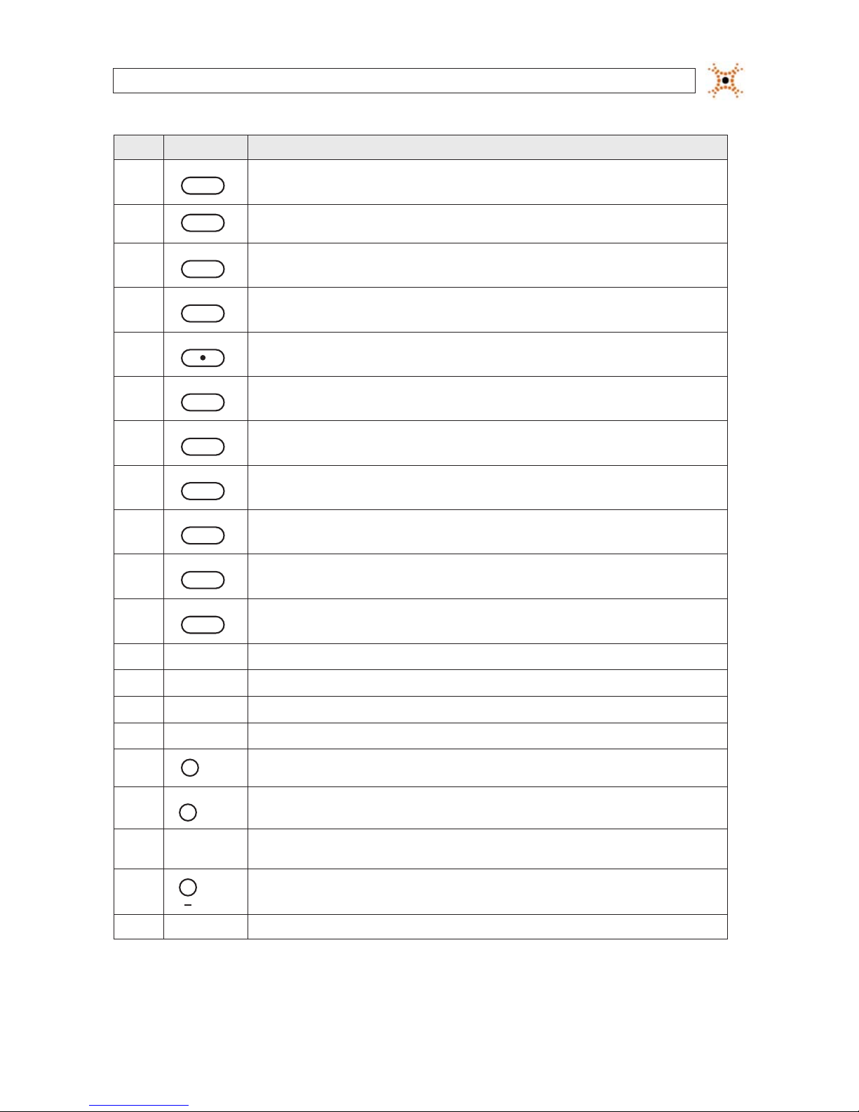
Table 2. Front Panel Buttons
No. Name Descript ion
1
Channel keys. For chann el 10, press the 0 key. For channel 11, press the +10 and 1 key. For channel 16, press the +10
and 6 key.
2
Press to rewind the vid eo in playback mode.
3
..
AUDIO
Press to selec t audio mode such as SINGLE (highlighte d channel), MIX (combin e all channels), or MUTE (all c hannels).
3H.264 DVR User Manual
No. Name Descript ion
4
..
AUDIO
Jump/step back ward. In playback mode, the play back position moves 60 seconds backward.
5
Press to fast forward the footage in playback m ode.
6
..
ALARM
Press to enable/disable ALARM operation.
7
..
ALARM
Jump/Step forward. In p layback mode, t he playback position moves 6 0 seconds for ward.
8
REC
Press to star t or stop manual recording.
9
/ ll
SEARCH
Press to open th e SEARCH menu in live display mode.
10
/ ll
SEARCH
Press to play/pause the recording in playb ack mode.
11
SETUP
Press to enter SE TUP menu.
12
SEQ
Enable/disable the automatic sequence display of channels in f ull screen, quad-split, and 9-split display mode.
13
PTZ
Press to contro l Pan/Tilt/ Zoom operations.
14
BACKUP
Press to capture live or playback mode v ideo in JPEG format.
15
t (LEFT)
Press to move lef t or to change the value s in Setup mode. When entering a p assword, it inserts a 4.
16
p (UP)
Press to move up th e menu in Setup mode. When entering a password, it insert s a 1.
17
u (RIGHT )
Press to move right or to change the values in Setup mode. When entering a p assword, it inserts a 2.
18
q (DOWN)
Press to move down the menu in Setup mode. When entering a p assword, it inser ts a 3.
19
SEL
Press to selec t desired menu item or to store the setup valu e.
20
ESC
Press f or temporar y storage of the changed value or to return to the previous menu scre en.
21 USB Port
Use with a USB ash drive to archive s till images and v ideos, and upgrade r mware, or use to connec t a USB mouse to
the DVR.
22
To open and close the inser t tray, press the button
23 DVD Drive To save vide o, insert a CD-R/DV D-R
SECTION 2: HARDWARE OVERVIEW

4
www.digiop.com
2.2 Rear panel
4-Channel DVR Rear Panel
8-Channel DVR Rear Panel
16-Channel DVR Rear Panel
Table 3. Rear Panel Connectors
No. Name Descript ion
1 VIDEO IN 16 connec tors for video inpu t.
2 CVBS
Spot out 1: Live view s creen.
Spot out 2: One channel screen w ith an event image.
3 AUDIO IN 4 RCA connectors for audio input.
4 AUDIO OUT RCA connector for au dio output.
5 VGA Connector for a VGA monito r.
6 RS-232 For factor y use only.
SECTION 2: HARDWARE OVERVIEW
5H.264 DVR User Manual
No. Name Descript ion
7 ETHERNET RJ- 45 connector for LAN connection.
8 SENSOR IN 4 connectors for sens or device conne ction.
9 AL ARM OUT Connec tor for alarm repor ting device. Provides simple On/O s witching by using a relay. 0.5A /125V, 1A/30V
10 RS-485 RS-485 control terminal
11 POWER SO CKET Connec t DC12V 5A adaptor
12 USB
Use with a USB ash drive to archive s till images and v ideos, and upgrade r mware, or use to connec t a USB mouse to the
DVR.
13 SATA Connector for e xternal SATA device
14 COOLING FAN
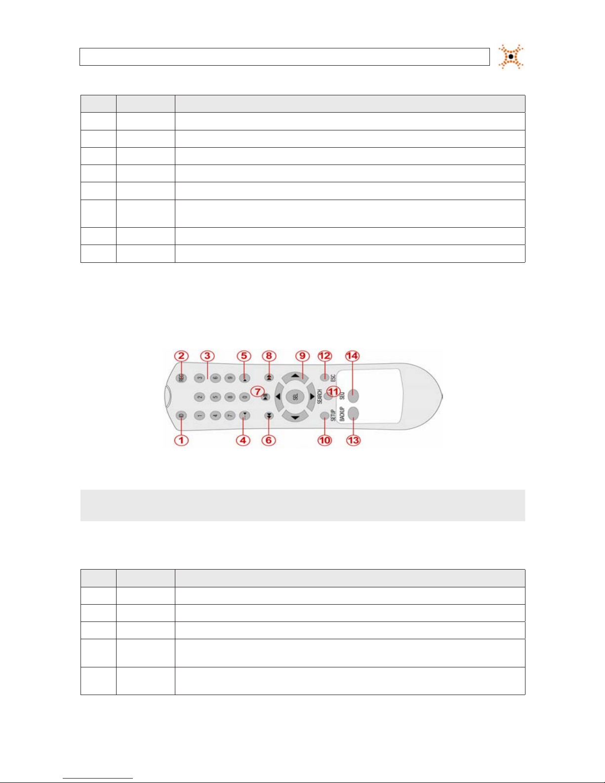
2.3 Remote Control
Typical Remote Control
NOTE
The remote control provided with your DVR may appear dierent from the one shown above. However, the buttons function as
described in the table below.
Table 4. Remote Control Button Functions
No. Name Function
1 ID When a remote cont rol ID number is se tup in DVR, press this bu tton before the number.
2 RE C To start and sto p manual recording.
3 0 .. 9 To select channel (1, 2, 3, ..) or to enter a DVR ID number.
4 F/RE W
During Playback – To move the p layback position 60 secon ds back.
During Pause – To move the playback position 1 frame back.
5 F/ADV
During Playback – To move the p layback position 60 secon ds forward.
During Pause – To move the playback position moves 1 frame for ward.
SECTION 2: HARDWARE OVERVIEW

6
www.digiop.com
No. Name Function
6 RE W To rewind the re cording. Pres s again to increas e the rewind spe ed.
7 PL AY/PAUSE To play or to p ause the recording in playback mode.
8 FF To fast forward the recordin g. Press again to increas e the fast forward spee d.
9
Direc tion
Buttons
Press to move to menu items or select a channel.
10 SETUP To open the SETUP menu.
11 SEARCH To go to the SEARCH menu.
12 ESC
During setup – To return to the previous menu screen.
During playback – To exit p layback mode
System lock – To lock a s ystem when pressin g ESC button f or 5 seconds.
System unlock – To unlock a sy stem when pressing ESC but ton for 5 seconds.
13 BACKUP To start a backup operations in live or playback mode.
14 SEQ To start auto se quencing the screen in full screen mode. ( Toggle)
SECTION 2: HARDWARE OVERVIEW
7H.264 DVR User Manual
SECTION 3
System Setup
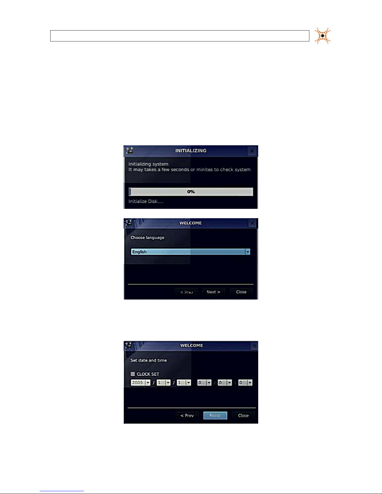
3.1 Starting the system for the rst time
When booting the system for the rst time, the following messages appear. After the initialization sequence completes, select your
preferred language and set the date and time.
When the Set date and time window opens, use the dropdown lists to show the correct date and time, then click Finish. The
date and time setting is used to timestamp recordings.
SECTION 3: SYSTEM SETUP
8
www.digiop.com
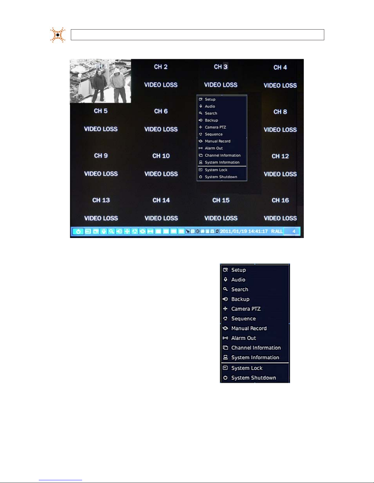
Typical System Desktop Display With One Camera Active
3.1.1 Entering the SETUP menu
1. To enter the SETUP menu, right click on the desktop or
press the SETUP button on the remote control, then click
the Setup
entry in the pop-up menu. A LOG-IN window
will open.
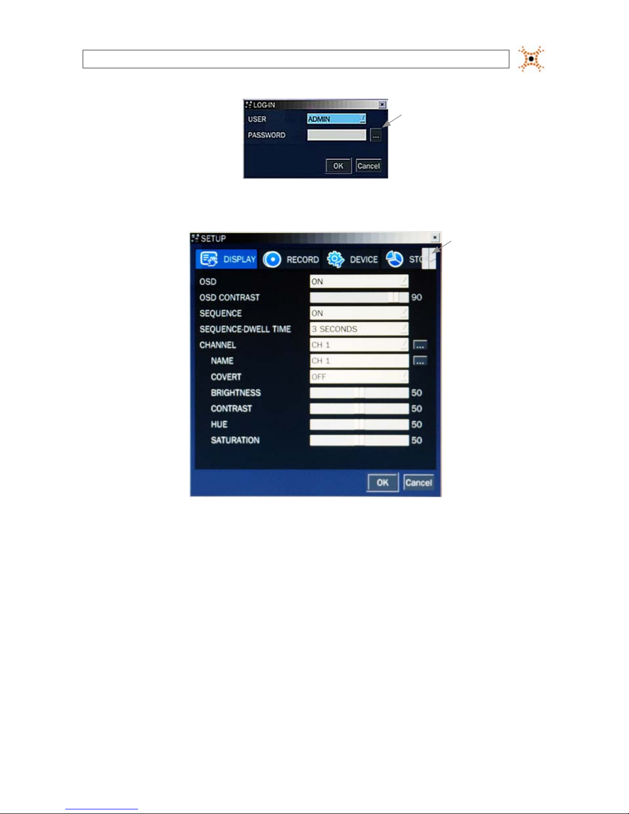
2. In the LOG-IN window, open the virtual keyboard and enter the PASSWORD, or use the direction buttons on the front panel.
The default password is “1111”. For improved security, DIGIOP recommends that you change the password at this time. You
can select a new password through the SECURITY tab in the SETUP menu.
SECTION 3: SYSTEM SETUP
9H.264 DVR User Manual
Virtual
Keyboard
Button
After entering the password, the SETUP window will open.
Shift
Tab List
Left/Right
Buttons
You can shift the tab list by clicking the left or right buttons in the upper-right corner of the window. Open a menu by
clicking the tab. To close the window, click Cancel. To save changes made to the menus before closing the window, click OK.
The SETUP menus include the following tabs:
— DISPLAY
— RECORD
— DEVICE
— STORAGE
— SYSTEM
— SECURITY
— NETWORK
— CONFIG
— QUICK SETUP
For a summary of the elements in each SETUP submenu (tab), refer to Appendix C.
SECTION 3: SYSTEM SETUP

10
www.digiop.com
SECTION 3: SYSTEM SETUP
Navigating the menus
Navigate through the menu items using the direction button, p, q, t, or u and change option values with the SEL
button. You can also navigate through the menu system, change option values, and click buttons with the mouse. Always
select (or click) OK to save new settings and close the SETUP menus. Press the ESC button at any time to exit the SETUP
menus.
NOTE
In the following descriptions of the SETUP menus, the instructions for navigating the system includes use of the front panel
buttons only. Using a mouse for menu navigation and setup of system options can be easier and faster.
3.2 DISPLAY menu
Opening the SETUP menu, or clicking the DISPLAY tab, opens the DISPLAY menu.
Open
Submenu
Button
Table 5. DISPLAY menu options
Item Descript ion
OSD Enable/disable the on-screen display.
OSD CONTR AST Set the visibili ty level of the OSD. (0 ~ 100)
SEQUENCE Enable/disable s equential display of video in f ull screen mode.
SEQ-DWELL TIME Set the dwell time of each quad-split or 9-channel display in sequential display mode. (3 - 60 seconds)
11H.264 DVR User Manual
SECTION 3: SYSTEM SETUP
Item Descript ion
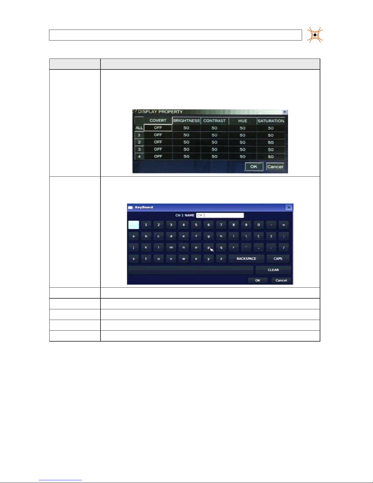
CHANNEL
Highlight the eld with the p or q bu ttons, use the t or u but tons to display a c hannel you want, t hen press SEL. You can
also highlight and select the submenu but ton to open the DiSPLAY PROPERTY window.
In the DiSPLAY PROPERTY window, use the p, q, t, and u buttons to highlight a par ameter, press SEL, use the p, q, t,
and u but tons to change the parameter v alue, then press SEL. Highlight t he OK button and pres s SEL to conrm the s ettings
and clos e the window.
NAME
Speci fy the channel name. Press SEL to open the vir tual keyboard, use the p, q, t, and u but tons and SEL button to enter
the channel name. Highlight the OK button and press SEL to conr m the settings and close th e keyboard window. The channel
name can have 10 characters at mos t.
COVERT Enable/disable display of the specied video channel in live display m ode.
BRIGHTNESS Change t he brightness value of the selected channel. (0 ~ 100)
CONTRAST Change the contras t value of the selected channel. (0 ~ 100)
HUE Change the hue value of the s elected channel. (0 ~ 100)
SATURATION Change the saturation value of the selected channel. (0 ~ 100)
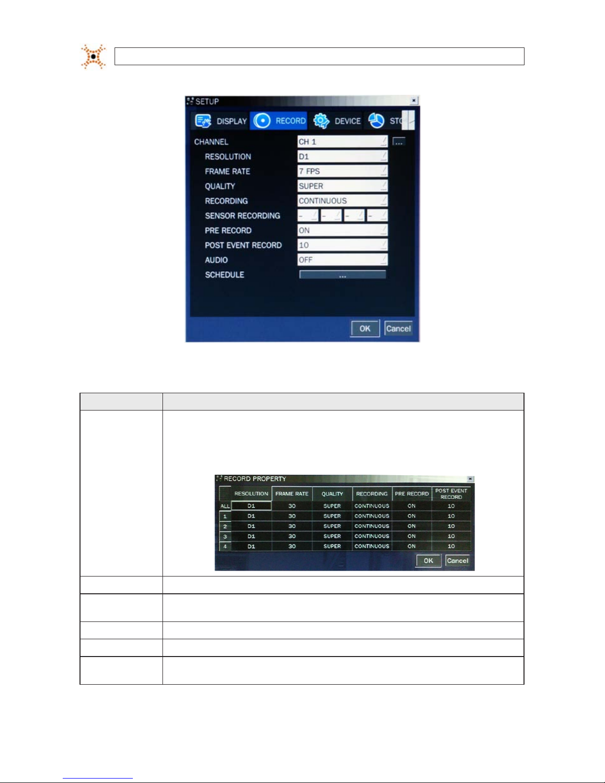
3.3 RECORD menu
Clicking the RECORD tab opens the RECORD menu.
12
www.digiop.com
SECTION 3: SYSTEM SETUP
Table 6. Menu Items in Recording Mode Setup
Menu Item D escription
CHANNEL
Highlight the eld with the p q buttons, use th e t u buttons to display a channel you want, then pre ss SEL. You can also
highlight and select the submenu button to open the RECORD PROPERTY window.
In the RECORD PROPERTY window, use the p, q, t, and u buttons to highlight a p arameter, press SEL, use the p, q, t,
and u but tons to change the parameter v alue, then press SEL. Highlight t he OK button and pres s SEL to conrm the s ettings
and clos e the window
.
RESOLUTION
Selec t either CIF, Half D1, or D1 using th e p, q, t, and u but tons.
FRAME RATE Set the frame rate for the specied channel. The sum of the frame rate value s from each channel cannot exce ed the maximum
frame rates f or a specic re cording resolutio n. The maximum video f rame rate is 120 fps.
QUALIT Y Selec t the recording quality for the specied channel. Options ar e: Network , Standard, High, Superior and Ultra.
RECORDING Assign the recording mode for each channel. Options are: Continuo us, By Motion, By Senso r, By Schedule, or Disable.
PRE RECORD Enable/dis able pre-event reco rding. Pre-event re cording time is 5 seconds (video from 5 s econds befo re the event is recorded
with the event t). Only intra-f rames are recorded during pre- event recording.

13H.264 DVR User Manual
SECTION 3: SYSTEM SETUP
13
Menu Item D escription
POST EVENT RE CORD Set the post event recording time duration fo r the specie d channel. (10 ~ 30 secon ds)
SENSOR R ECORDING
Enable s etting up to 4 sensor s for the spec ied channel using the p, q, t, or u but tons.
AUDIO Enable/disable audio recording for the specied channel. Available only on channel 1 through channel 4.
SCHEDULE Set the recording schedule. Press SEL to open the SCHEDULE window. .
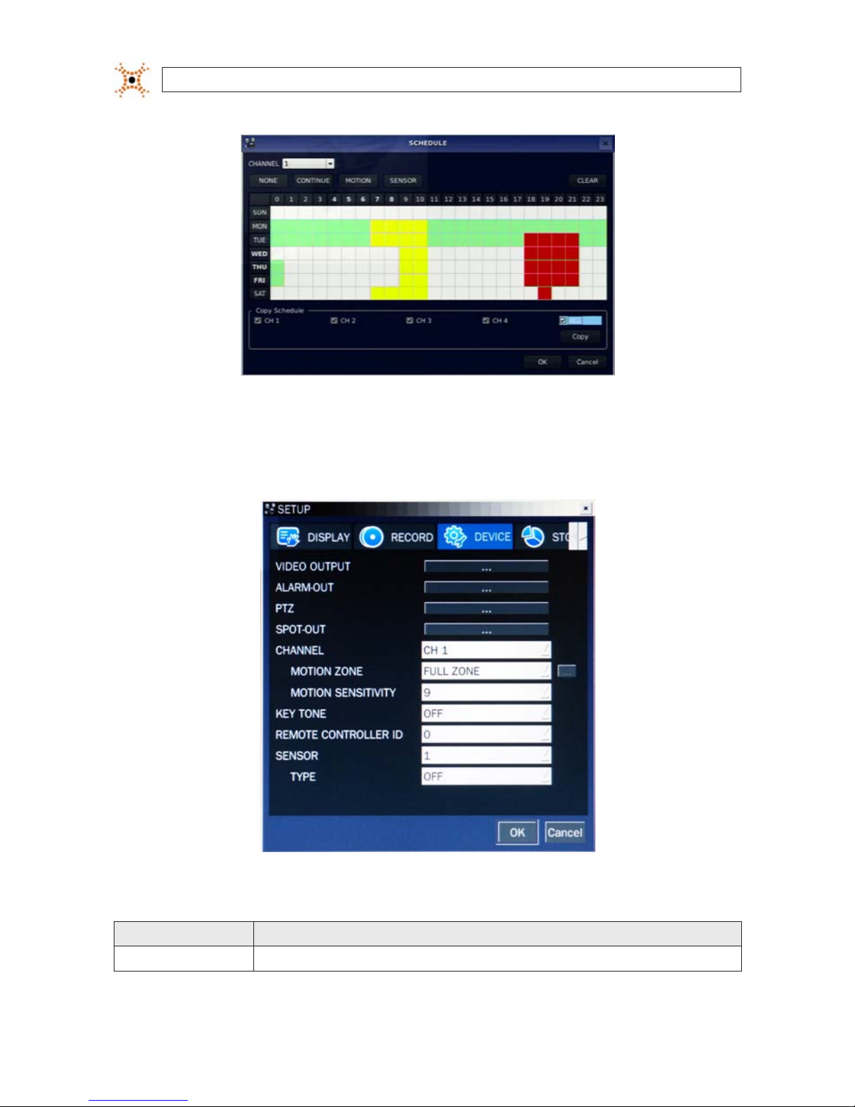
3.3.1 Recording Schedules
To setup a recording schedule, select SCHEDULE in the RECORD menu. Navigate through the items using the p , q, t, and u
buttons.
[CHANNEL]: Select the specic channel.
[SETUP]: Use
p and q buttons to highlight a record type (None, Continuous, Motion, Sensor), then press SEL to select it. Use the
p, q, t, and u buttons to highlight a timeslot in the schedule, then press SEL to apply the record type to that timeslot. Repeat
this to apply other record types to other time slots. Select the ALL option to apply the schedule to all cameras channels. You can
select or deselect any option by clicking it with a mouse, and you can select a block of timeslots by clicking and dragging the mouse
across them. Timeslots are color coded for the record type applied to them: CONTINUOUS - green, MOTION - yellow, and SENSOR red, None - white.
[COPY Schedule]: To copy the schedule setup on channel 1 to channel 2, select the channel 1 schedule, select COPY using the
p, q,
t,
and u buttons, select CH2 using the p, q, t, and u buttons, then press the SEL button.
To return to SETUP menu screen, press the ESC button.
14
www.digiop.com
SECTION 3: SYSTEM SETUP
3.4 DEVICE menu
Clicking the DEVICE tab opens the DEVICE menu. To return to SETUP menu, press the ESC button.
Table 7. Menu Items in Device Setup Screen
Item Descript ion
VIDEO OUT Opens a submenu to select the VGA vide o resolution: 1024 x 768 or 1280 x 1024
15H.264 DVR User Manual
SECTION 3: SYSTEM SETUP
Item Descript ion
ALARM OUT Set the sensor, motion, and vide o loss for each alarm.
PTZ Set the PTZ cam era speed, number, type and ID.
SPOT-OUT Set th e conguration for SPOT 2 monito ring only.
CHANNEL Selec t specied channel for motion zone setup.
MOTION ZONE Selec t either Full Zone or Par tial Zone for motion sensing.
MOTION SE NSITIVITY Set the motion sensitivity for the sp ecied channel. (1 ~ 9).
KEY TONE Enable/dis able tone when key is pressed. .
REMOTE CONTROL ID Sele ct an ID for the remote control.
1. Selec t ID number.
2. On the remote control, press the same number a s the ID set in the DVR.
3. An icon will be displayed on L ive screen that corresponds to the remote control. (0 ~ 99)
SENSOR Selec t sensor numb er. (1 ~ 4)
TYPE Set the type of sensor for the specie d channel. (OFF, N/O (normal op en), N/C (normal closed)).
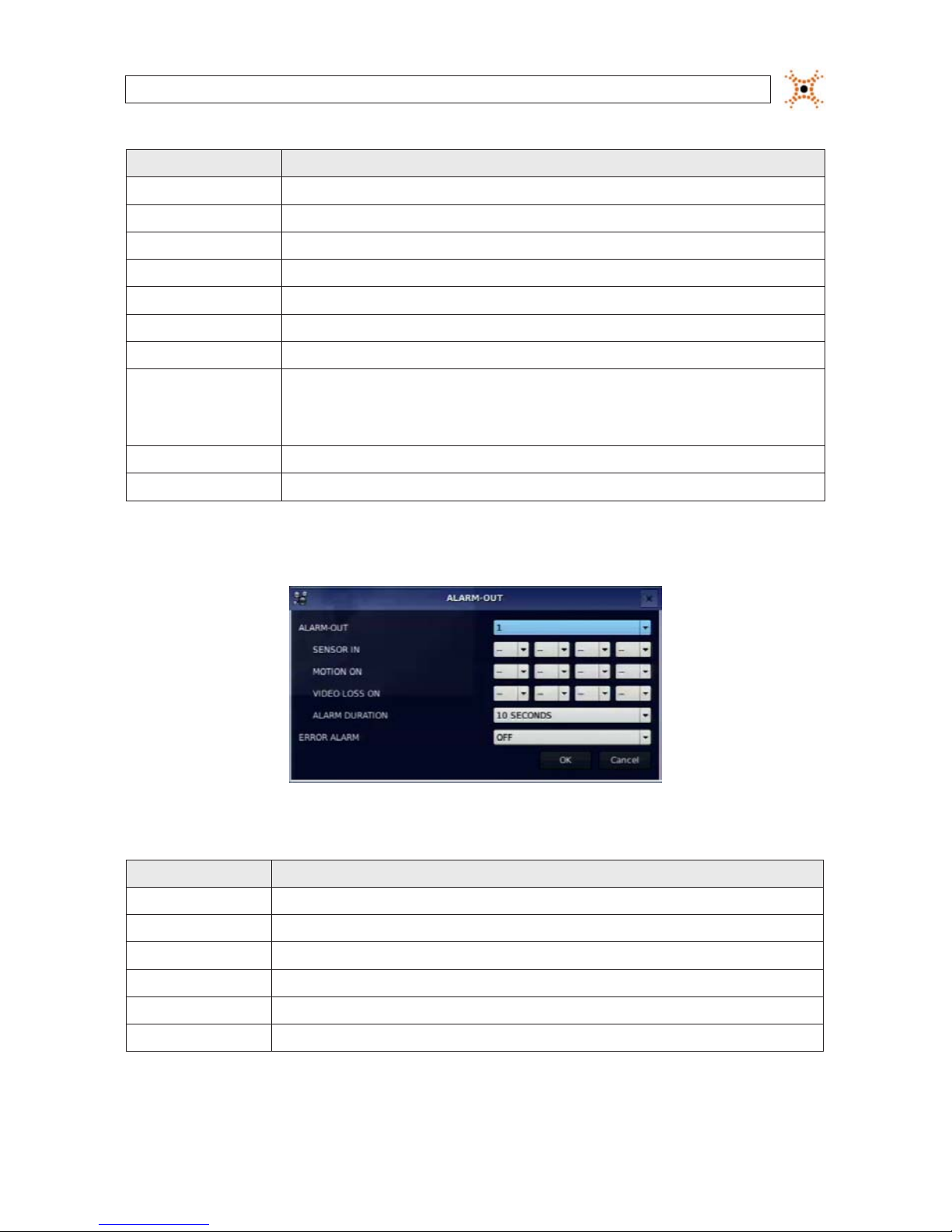
3.4.1 ALARM OUT submenu
Table 8. Menu Item in ALARM-OUT Setup Screen
Item Descripti on
ALARM OUT 1 only.
SENSOR IN Enable s etting 1 of 4 cameras f or each alarm.
MOTION ON Enable setting 1 of 4 cameras for each alarm.
VIDEO LOSS ON Enable set ting 1 of 4 cameras for each alarm.
ALARM DURATION Set the alarm dwell time. (5 ~ 6 0 seconds).
ERROR ALARM Set the error type for the alar m activation. (OFF, ALL, HDD ERROR , VIDEO LOSS).
16
www.digiop.com
SECTION 3: SYSTEM SETUP
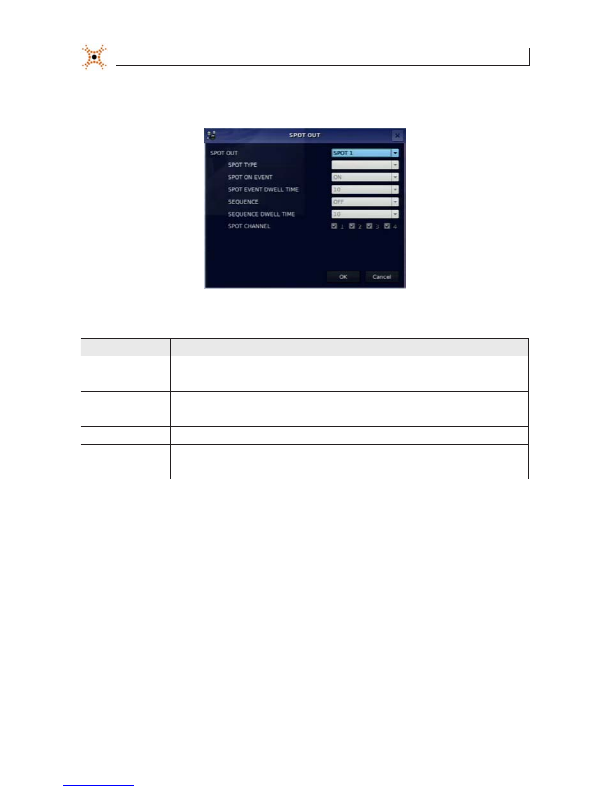
3.4.2 SPOT-OUT setup
Table 9. Menu Item in SPOT-OUT Setup Screen
Item Descript ion
SPOT OUT SPOT 2 only
SPOT TYPE SPOT 2 supports FUL L type.
SPOT ON EVENT Enable/disable display of the channel when an event is act ive. SPOT 2 displays when event is ac tive.
SPOT EVENT DWELL TIME Set the dwell time for the event activated c hannel (1 - 10 sec).
SEQUENCE Enable/disable sequential display of sp ot channel(s) in full s creen. If ON is selec ted, the spot channel is displaye d.
SEQUENCE-DWELL TIME Set the dwell time for the spot channel display (1-10 sec).
SPOT CHANNEL
Selec t a channel for spot monitoring. Press SEL and s elect channel using the p, q, t, and u butto ns, then press SEL.
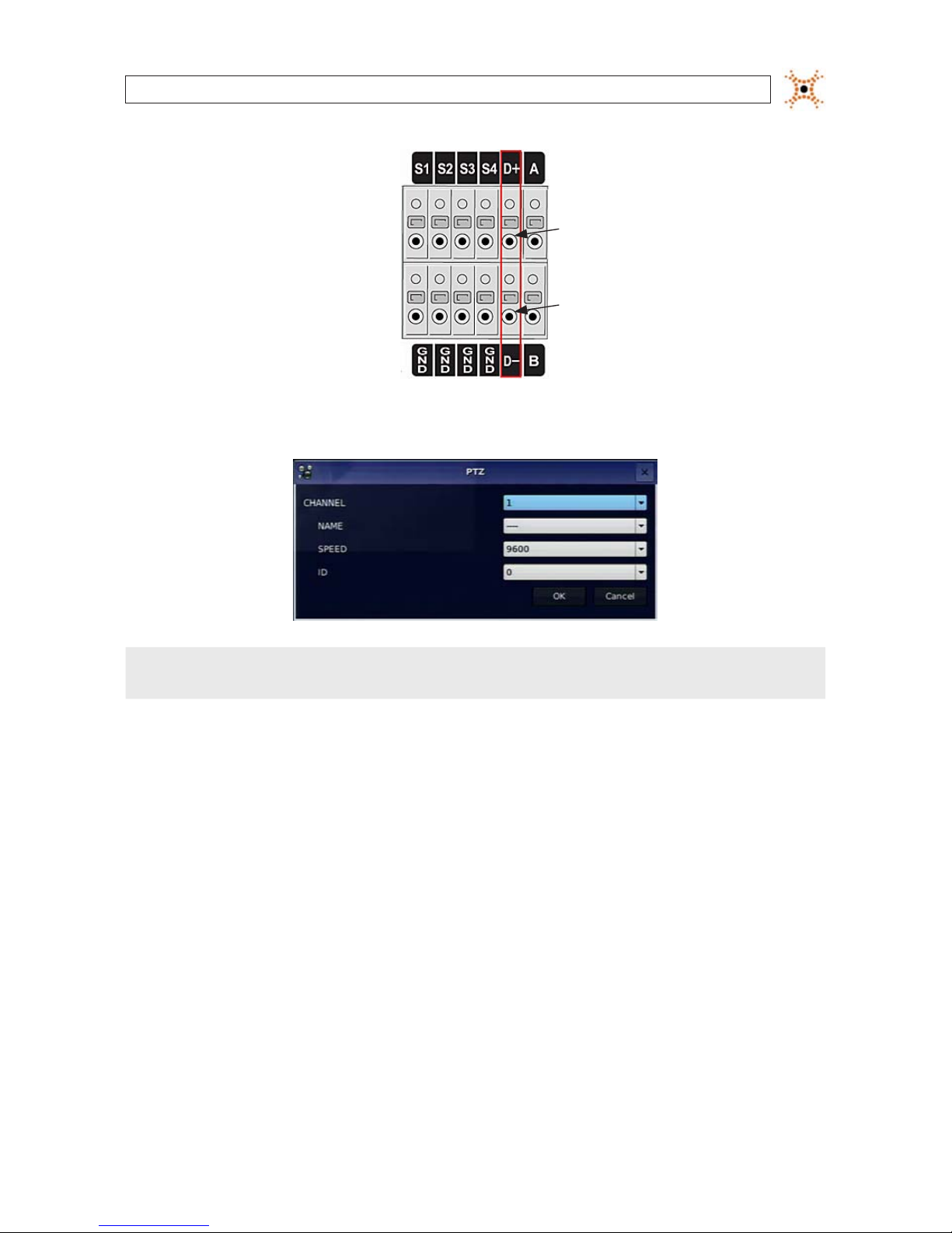
3.4.3 PTZ Setup
To control the PTZ functions of the camera, connect the PTZ controller to the RS-485 port on the back of the chassis with CAT 5 (or
equivalent) cable.
17H.264 DVR User Manual
SECTION 3: SYSTEM SETUP
RTS-485 D+
RTS-485 D-
Open the PTZ submenu by selecting the submenu button.
NOTE
Connect speed dome cameras that support RS-485 directly to the RS-485 port. If the camera is controlled through an RS-232C
interface, use an RS-232C to RS-485 signal converter.
Use the PTZ setup screen to select the following options for the camera PTZ controller:
CHANNEL: Channel connected to a PTZ device
NAME: Protocol type
SPEED: 19200, 14400, 9600, 4800, 2400
ID: 0 ~ 63
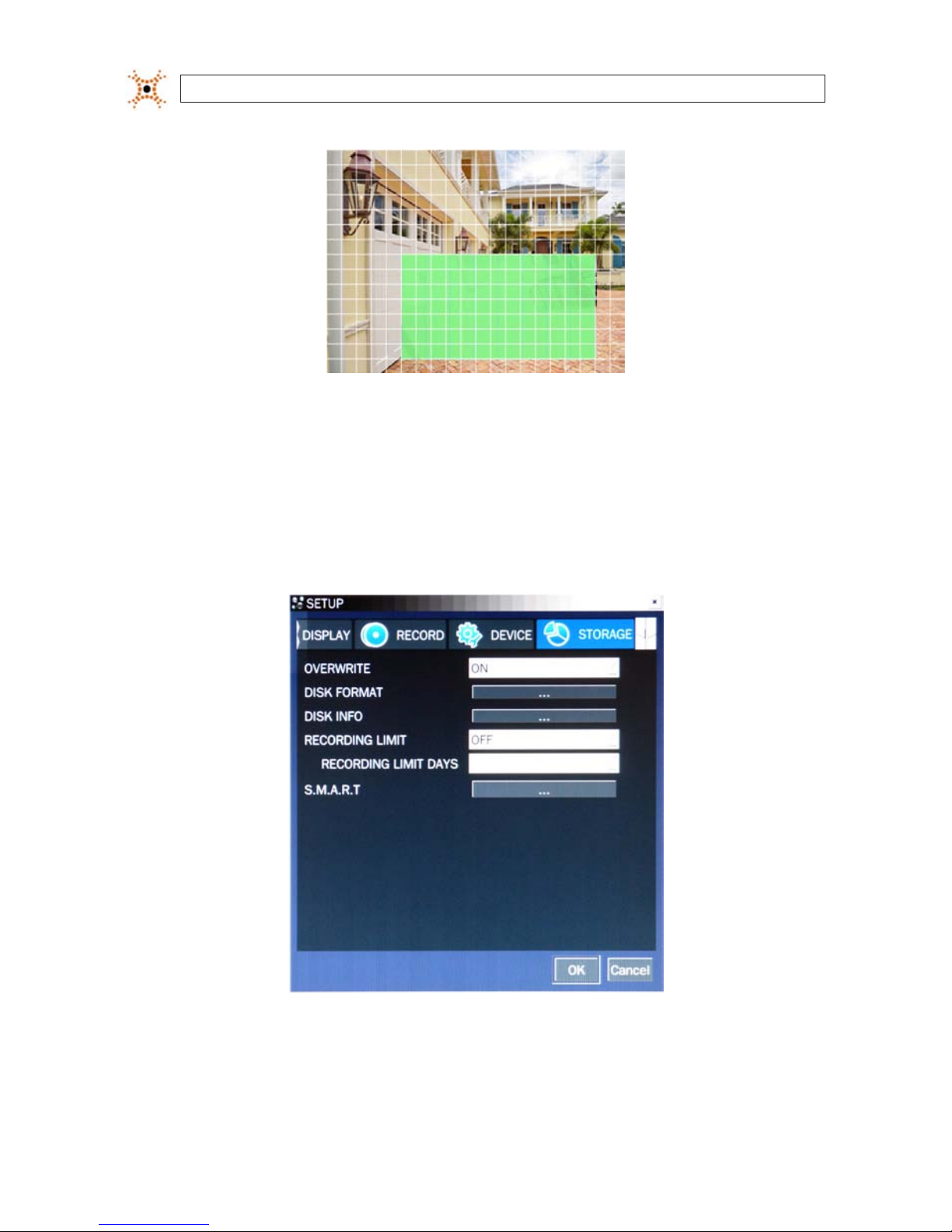
3.4.4 MOTION ZONE Setup
Select MOTION ZONE using the p, q, t, and u buttons, select either PARTIAL ZONE or FULL ZONE, then press SEL.
FULL ZONE: The motion sensor is active on the whole screen. Set the level of sensitivity for MOTION SENSITIVITY.
PARTIAL ZONE: The motion sensor is active in the set detection frame (highlighted in green). To select or deselect a block
for motion detection, use the
p, q, t, and u buttons to move to the block, then press SEL. Press ESC to return to the
DEVICE menu.
18
www.digiop.com
SECTION 3: SYSTEM SETUP
Partial Zone Detection Area (in green)
3.5 STORAGE menu
Clicking the STORAGE tab opens the storage menu. Navigate through the menu items using the p, q, t, and u buttons, press
SEL to select the item, use the
p, q, t, and u buttons to change the value, then press SEL again to conrm that value. Move to
the next item you want to change using the
p, q, t, and u buttons. To return to setup menu screen, press ESC.
19H.264 DVR User Manual
SECTION 3: SYSTEM SETUP
Table 10. Menu Items in STORAGE Setup Screen
Item Descript ion
OVERWRITE If enabled, the DVR will continue recording when the drive is full, overwriting the oldest information rst. If dis abled, record-
ing will s top when the hard drive is f ull.
DISK FORMAT Selec t YES or NO to format th e hard drive (disk). Caution: Formatting the hard dri ve will erase all information on the disk.
Archive all data that you may need before formatting the disk.
DISK INFO Hard dri ve information
RECORDING LIMIT Enable/disable a recording limit.
RECORDING LIMIT DAYS Set the recording limit in days (1- 90 days). If set to 1 day, data old er than 24 hours will b e removed.
S.M.A .R.T. Use to set the HDD temperature limit.
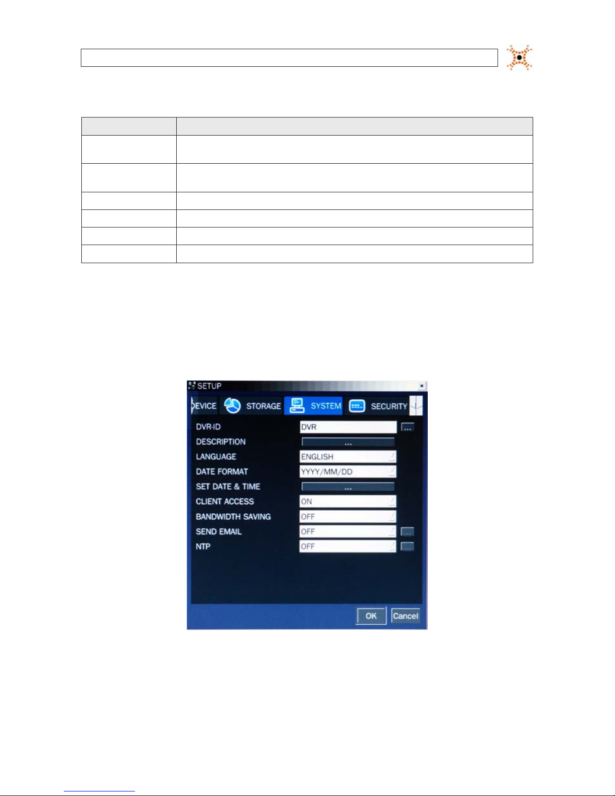
3.6 SYSTEM menu
Clicking the SYSTEM tab opens the system menu. Navigate through the menu items using the p, q, t, and u buttons, press SEL
to select the item, use the
p, q, t, and u buttons to change the value, then press SEL again to conrm that value. Move to the
next item you want to change using the
p, q, t, and u buttons. To return to SETUP menu screen, press the ESC button.
20
www.digiop.com
SECTION 3: SYSTEM SETUP
Table 11. Menu Items in SYSTEM Setup Screen
Item Descript ion
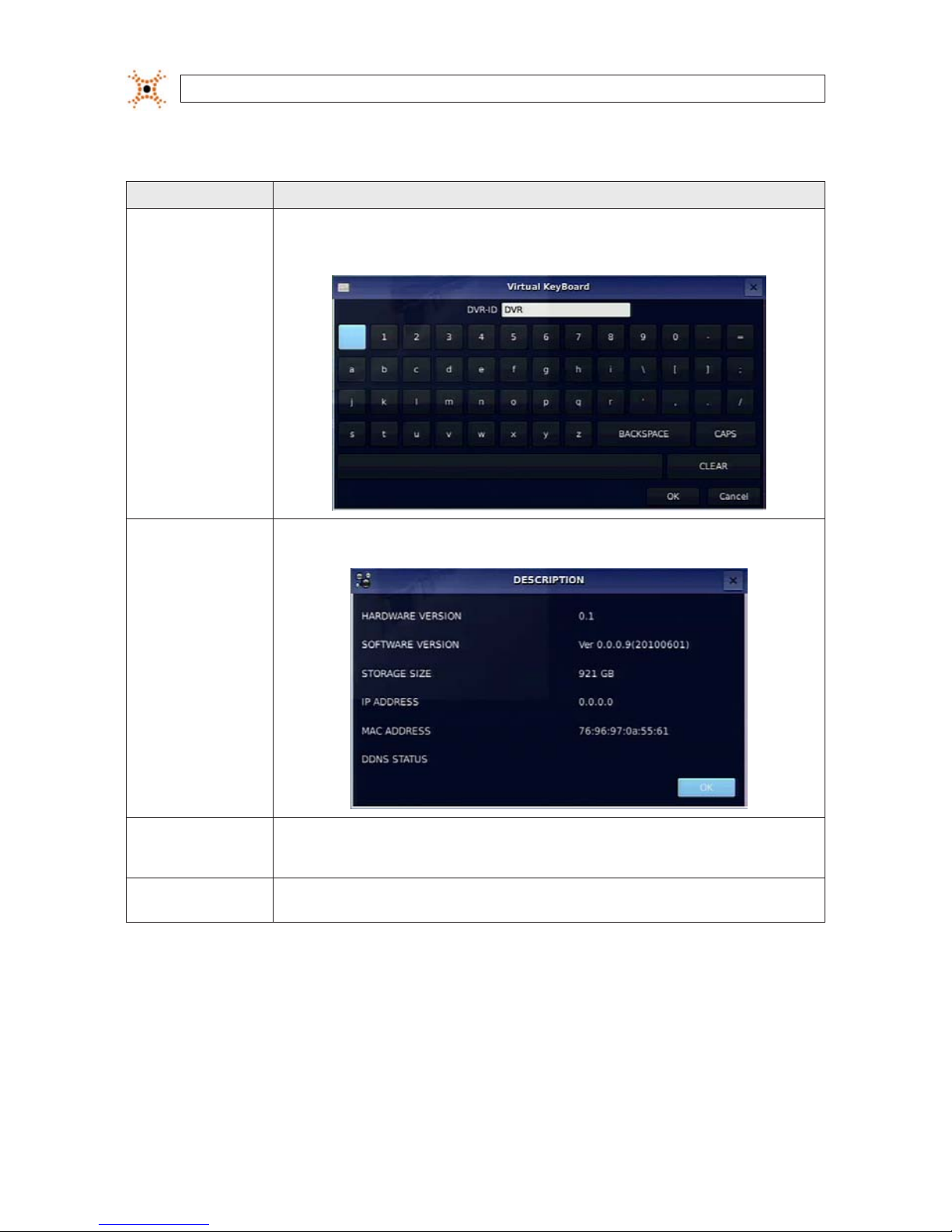
DVR ID
Selec t the submenu button to open the vir tual keyboard. Press SEL to open the virt ual keyboard, use the p, q, t, and
u and SEL buttons to enter t he DVR ID, then highlight the OK b utton and pre ss SEL to conrm your sele ction and clo se the
keyboard window. The DVR ID c an have a most 10 characters.
DESCRIPTION Press the SEL but ton to view system information (hardware version, sof tware ver sion, storage size, IP ad dress, MAC address,
and DDNS s tatus).
LANGUAGE
Selec t the display language using the p, q, t, and u but tons. When a language is selec ted, the scre en language
change s. Options inc lude: English, Korean, Jap anese, SP Chine se, TR Chinese, Czech, Finnish, French, Greek, Italian, Dutch,
Norse, Russian, Spanish, Turkish, Polish, Danish, Persian, Croatian, Ger man, Portuguese, Portu guese (Brazil), Arabic..
DATE FORMAT
Selec t the date format using the p, q, t, and u buttons. Options include: YYYY/MM/DD, MM/DD/Y YYY, DD/MM/YYYY,
YYY Y-MM-D D, MM-DD -YYY Y, DD-MM-YY YY.
21H.264 DVR User Manual
SECTION 3: SYSTEM SETUP
Item Descript ion
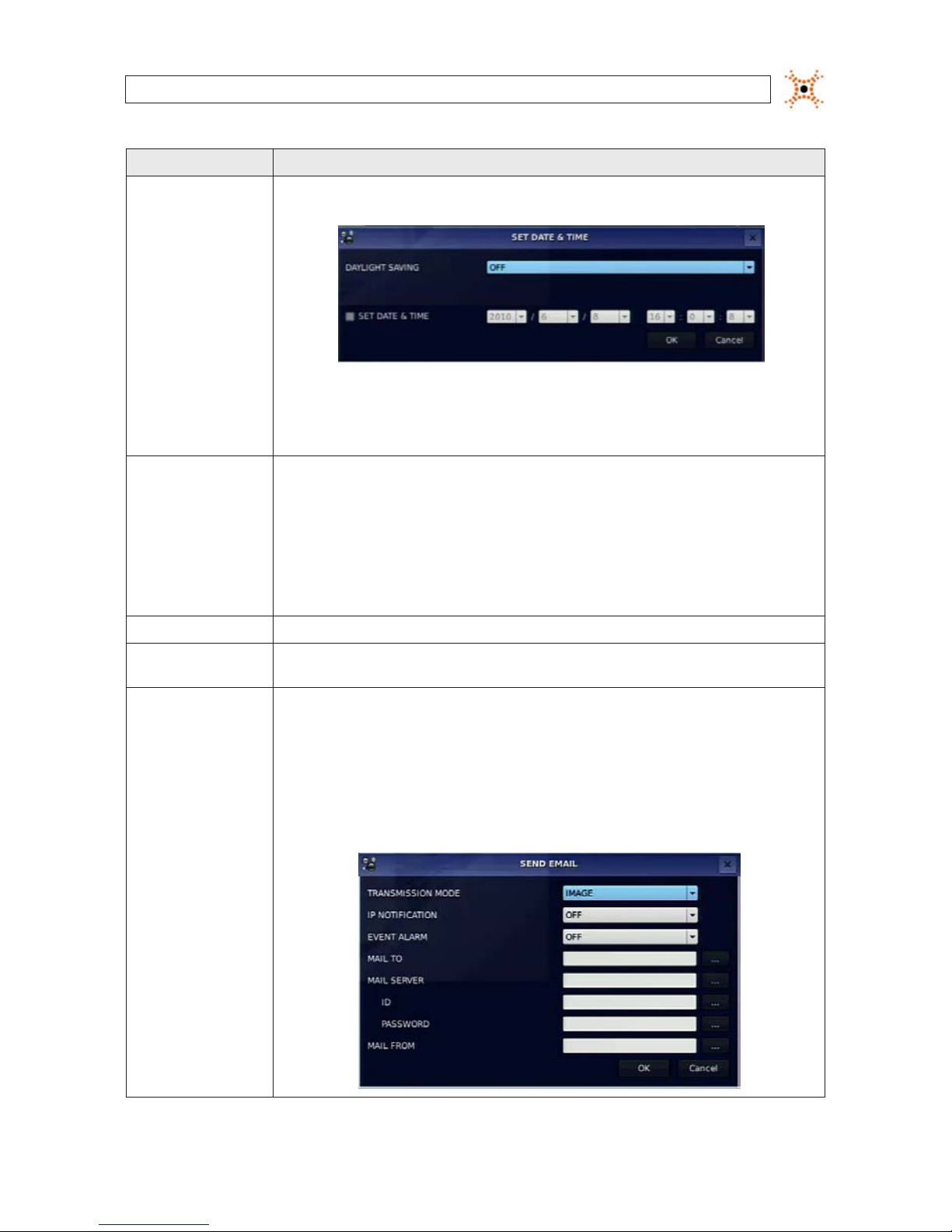
SET DATE & TIME
To set the date and tim e, move the cursor to SET DATE & TIME submenu but ton using the p, q, t, and u but tons, then
press t he SEL button.
In the SET DATE & TIME window, use th e t and u buttons to change the timestamp component value, then pres s SEL to
conrm i t and move to the next eld. To move to another eld without changing it, use the p and q buttons. Highlight
the OK button and press SEL to conrm your sele ction and clo se the window, or press ESC but ton to return to SYSTEM setup
menu.
DAY LIGHT SAVING: Move the cursor to DAYLIGHT SAVING using the p and q but tons, change t he option shown with the
t and u but tons, then pre ss SEL to conrm your sele ction. Sele ct the appropriate daylight savin g time zone using t he p,
q, t, and u but tons. If choo sing EU or OTHERS, s et the applicable conditions. The o ptions are:
USA: Applies the USA daylight saving time.
EU: Applie s the EU daylight saving time. Select the GMT AREA and the time dierence from standard time usin g the p, q,
t, and u but tons.
OTHERS: If the time zone is neither USA nor EU, set the BEGIN and END date and time of the daylight saving period using the
p, q, t, and u but tons, then press the SEL button. Pre ss the ESC but ton to return to SET DATE & TIME s etup menu.
CAUTION: Do not set the s tart time to 2 3:00 for DLS. DLS can’t be applied if the date of BEGIN and END is the same.
CLIENT ACCESS Enable/Disable remote access through net work client soft ware.
BANDWIDTH
SAVING
Enable/Disable only key frame transmission. “ON” mode is recommended for use on low-band width network s. Set to “OFF”
for nor mal use.
SEND EMAIL Enable/dis able the send email feat ure (ON/OFF).
TRANSMISSION MODE: When an alarm is triggere d, send an image of only the channel that triggered the alarm.
IP NOTIFIC ATION: Enable/disable sending email when the IP address of your DVR is changed.
EVENT AL ARM: When an alarm is triggered, enable/disable sending email repor ts of the channel that triggered t he alarm.
MAIL TO: Us e the virtual keybo ard to enter the email addre ss of the recipient.
MAIL SERVER: Use t he virtual keyboard to enter the mail s erver infor mation.
ID: Use the vir tual keyboard to spec ify the user ID for the mail server.
PASSWORD: Use the v irtual keyb oard to specify the connection password f or the mail ser ver.
MAIL FROM: Use the virt ual keyboard to specify the email addres s sent to the destination hos t.
22
www.digiop.com
SECTION 3: SYSTEM SETUP
Item Descript ion
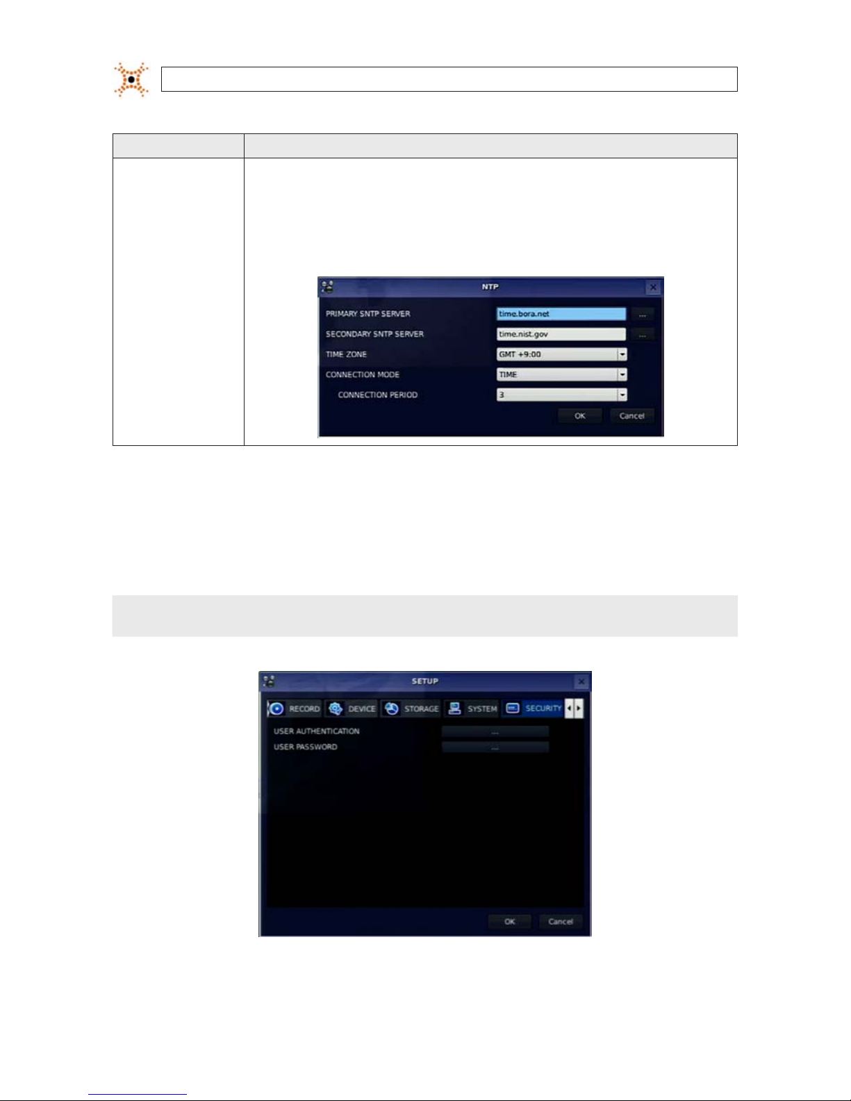
NTP NTP (Net work Time Protocol): Us e to synchroni ze the clocks of computer systems over variable-latency dat a network s.
PRIMARY SNTP SERVER: Use the vir tual keyboard to enter the address of the primary NTP time s erver.
SECONDARY SNTP SERVER: Use the vir tual keyboard to enter the address of the secondar y NTP time server.
TIME ZONE: Select the oset from GMT (Greenwich Mean Time).
CONNECTON MODE: Select an NTP time server connection mode (INTERVAL/TIME).
INTERVAL: Synchronize the clock by hours shown on the connection period option.
TIME: Synchronize the clock at t he time daily show n on the connec tion period m enu. CONNECTI ON PERIOD: 1 ~ 24.
3.7 SECURITY menu
Clicking the SECURITY tab opens the security menu. Navigate through the menu items using the p, q, t, and u buttons, press
SEL to select the item, use the
p, q, t, and u buttons to change the value, then press SEL again to conrm that value. Move to
the next item you want to change using the the
p, q, t, and u buttons. To return to setup menu screen, press the ESC button.
NOTE
You must be a user with Admin permissions to congure the SECURITY menu.
23H.264 DVR User Manual
SECTION 3: SYSTEM SETUP
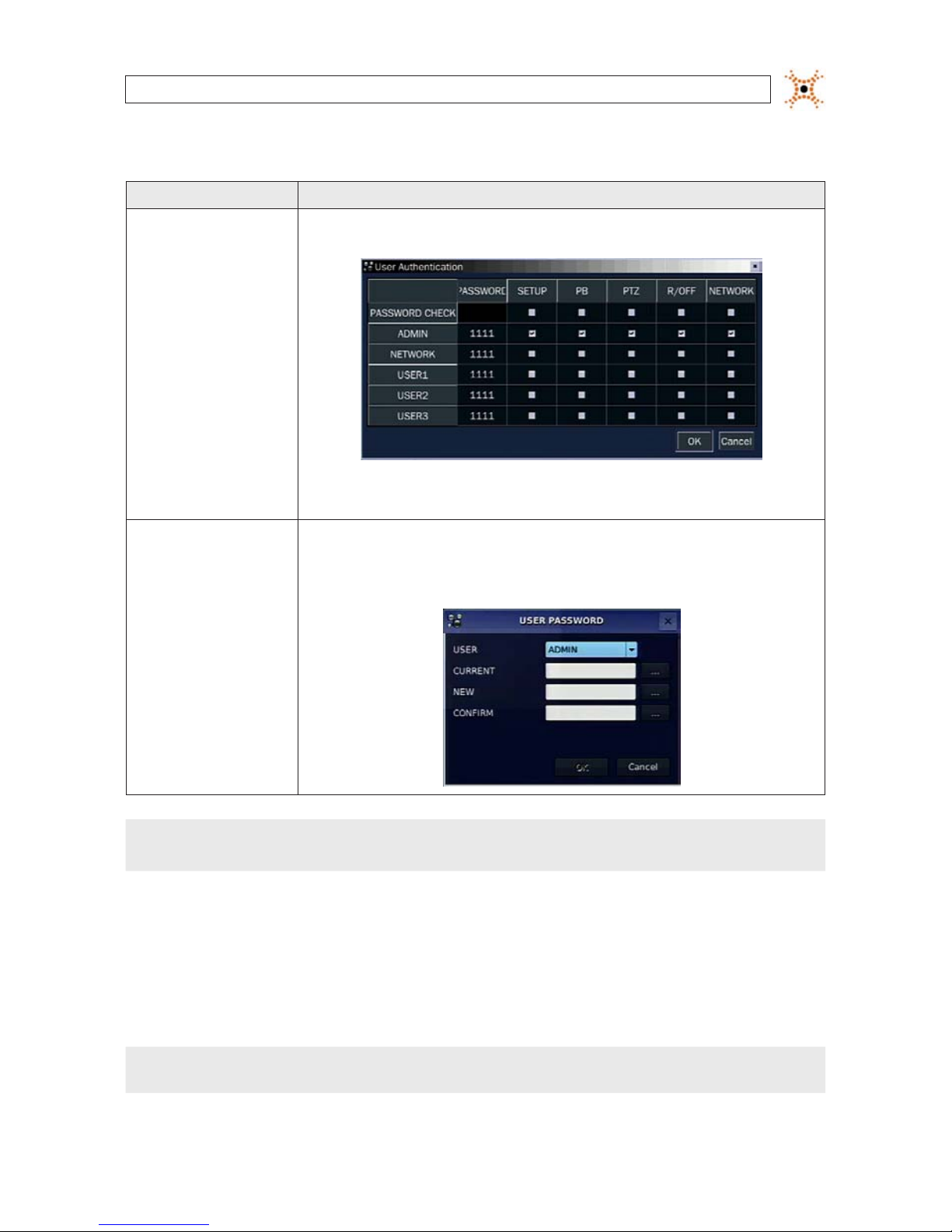
Table 12. Menu Items in PASSWORD Setup Screen
Item Descript ion
USER AUTHENTIC ATION PASSWORD CHECK: Select either V or nothing for the functions such as SETUP, PB (playback), PTZ, R/O FF (record o),
and Net work.
In the PASSWORD CHECK row, check or uncheck t he box to selec t for all users, o r check or uncheck the individual settings for each user. Pres s ESC to return to the SECURITY menu.
USER PASSWORD
In the USER PASSWORD window, move the cur sor to the USER eld with p and q but tons, then use the t and u
buttons to display the username. Op en the virtual keyboard fo r each subsequent entry to sp ecify the p asswords. Move
to the OK button and press SEL to conrm t he setting s and return to the SECURITY menu. The message “PASSWORD
CHANGED” will be displayed. The fac tory default password is 1111.
NOTE
For improved system security, it is strongly recommended that you change the factory default password during the initial setup
of your system.
3.8 NETWORK menu
Clicking the SECURITY tab opens the security menu. Navigate through the menu items using the p, q, t , and u buttons, press
SEL to select the item, use the p, q, t, and u buttons to change the value, then press SEL again to conrm that value. Move to
the next item you want to change using the
p, q, t , and u buttons. To return to setup menu screen, press ESC.
NOTE
You must be a user with Admin permissions to congure the NETWORK menu.
24
www.digiop.com
SECTION 3: SYSTEM SETUP
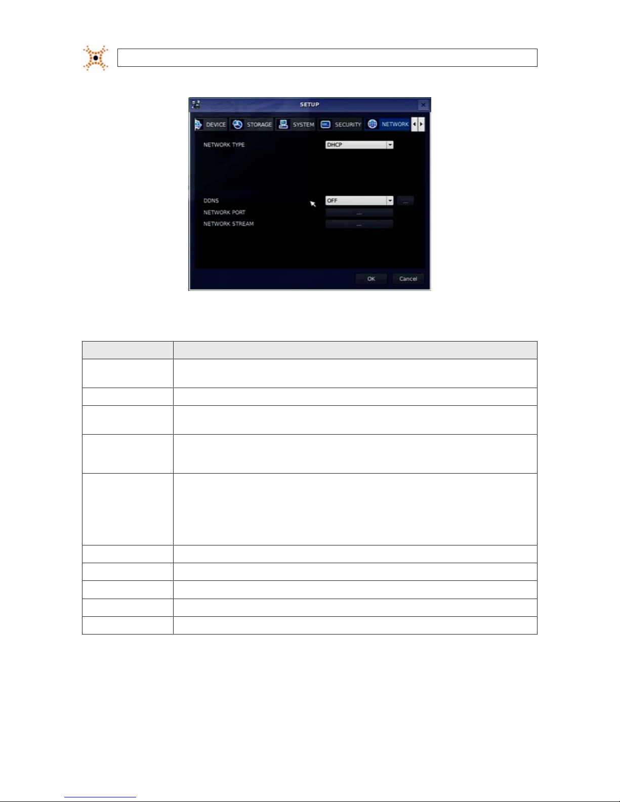
Table 13. Menu Items in the NETWORK menu
Item Description
NETWORK TYPE Select a typ e of network connec tion. Options are: DH CP, ADSL, LAN. NOTE: D epending on the selectio n, the options in t he
network menu will change app ropriately.
DHCP If selec ted, the DVR automatically acquires an IP address from a DHCP server. This address may c hange withou t notice.
ADSL (PPPoE) ID: Registere d ID is necessary for ADSL conn ection.
Password: A registered p assword is necessary for an ADSL connec tion.
LAN IP: Enter t he IP address as signed to the DVR . This address is xed until it is manually change.
GATEWAY: Enter the Gateway IP address assigned for the DVR.
SUBNET MASK: E nter the Subnet Mask for the subnet where the DVR is conne cted.
DDNS Enable/disable use of a do main name server through which you acce ss the DVR. If “ON ”, the DDNS server name appears in the
eld.
DDNS 1: Select one of the fo llowing DDNS server s: in USA, use ww w.ddnscenter.com, in Korea, use ww w.okddn s.com, or
if in the eu, or use w ww.bestd dns.com.
DDNS 2: Select this t ype to use a gener al-purpos e DDNS Server.
DDNS INTERVAL: Set t he connection interval (5 - 6 0 minutes).
NETWORK PORT Set a por t number for connec ting to network.
PORT Port number (default: 5445)
WEB PORT Web sever po rt number (def ault: 80)
PORT FORWARD Set the port f orwarding for connecting to network.
NETWORK STREAM Set t he value for net work streaming.

25H.264 DVR User Manual
SECTION 3: SYSTEM SETUP
3.8.1 DHCP networks
When the DHCP option is selected, the IP address and other network parameters are automatically assigned by the DHCP server. If
the network connection is reset, the assigned network parameters may change. ADSL and other network types that use a variable IP
address method use this process to acquire an IP address.
3.8.2 ADSL (PPPoE) networks
Select the ADSL (PPPoE) option when the DVR is connected to a network using PPPoE (Point-to-Point Protocol over Ethernet). If
the ADSL connection is not inputting the IP address and password through VDSL, or if DVR is installed in IP sharer, do not select this
option; select DHCP or LAN.

26
www.digiop.com
SECTION 3: SYSTEM SETUP
3.8.3 LAN networks
Select the NETWORK TYPE - LAN if:
• You are using with a xed IP address. See your network administrator to obtain network settings.
• The DVR is installed on an IP sharer that is connected thorough an ADSL modem. In this conguration, a user can assign a xed
IP address to the DVR from the IP sharer using the “DMZ” function. Enter the IP address set in DMZ into the IP address eld,
and Gateway of ADSL modem into the Gateway eld. Similarly, for Subnet Mask, DNS address, input relevant values for the
IP sharer.
Table 14. NETWORK - LAN menu options
Item Description
IP The xed IP address of the DVR hardware. .
SUBNET MASK The subnet mask fo r the LAN.
GATEWAY The IP address of t he Gateway.
1st DNS The IP address fo r the DNS server.
2nd DNS The IP ad dress for the DNS ser ver.
3.8.4 DDNS option
DDNS options include:
OFF: The DDNS option is not used.
SERVER1: This option allows you to choose one of three free DDNS servers: ddnscenter.com (USA), bestddns.com (EU and
other areas), and OKddns.com (Korea). To connect to a network with a domain name, user must register a MAC address and

27H.264 DVR User Manual
SECTION 3: SYSTEM SETUP
create a unique domain name to http://www.bestddns.com, http://www.okddns.com or http://www.ddnscenter.com. The
DDNS interval can be set from 5 to 60 minutes.
SERVER2: This option allows you to connect to a general purpose DDNS server. With this selection, you can enter a DDNS ID
and password.
3.8.5 Network ports
When you connect one or more DVRs to a network through an IP sharing device, each DVR must be assigned a unique TCP port
number for access from outside the LAN. Additionally, the IP sharing device must be congured to forward the assigned port to the
specic DVR.
NOTE
This port number is listed next to the Port menu option in the Network Setup screen. If you access the DVR only from within the
same LAN, the TCP port number does not need to be changed.

28
www.digiop.com
SECTION 3: SYSTEM SETUP
Network access beyond a router
To access the DVR beyond a router (rewall), you must open TCP ports for commands, for live channels, and for storage channels.
The default DVR port numbers 5445 and the web port number 80. If this port is not opened properly, you cannot access the DVR
outside a router.
3.8.6 Network stream
You can set the frame rate and bit rate for a network stream by channel. The total frame rate is CIF (352 × 288 ) at 120 fps. The bit
rate can be set to 128, 256, 384, 512 or 768.
3.8.7 CONFIG menu
Clicking the CONFIG tab opens the system conguration menu. Navigate through the menu items using the p , q, t, and u
buttons, press SEL to select the item, use the
p, q, t, and u buttons to change the value, then press SEL again to conrm that
value. Move to the next item you want to change using the
p, q, t , and u buttons. To return to the setup menu, press the ESC
button.

29H.264 DVR User Manual
SECTION 3: SYSTEM SETUP
Table 15. CONFIG menu items
Item Description
SAVE SETUP TO A USB Save the c urrent system conguration to the USB ash drive. Plug the ash drive into the USB por t on the front panel and p ress SEL
to star t the save process.
LOAD SETUP FROM
A USB
You can upload the conguration of DVR to another DVR using the USB ash drive. Plug the ash drive into the f ront panel USB port
and press SEL to start the loa ding process.
LOAD DEFAULT Selec t ON to reset th e system to the d efault set tings. The following items are not reset: language, DVR ID, Securit y User Authentica-
tion, Se curity User P/W, date format, DL S settings, net work settings, HDD over write, limit re cording, HDD serial number, and HDD
ERROR t ime.

30
www.digiop.com
SECTION 3: SYSTEM SETUP
Item Description
LOAD FACTORY
DEFAULT
Selec t ON to reset th e system to the f actory defaul t settings .
3.9 Save setup
When conguration changes are made, a SAVE SETUP conrmation window will open. Select YES to save the changes you made.

31H.264 DVR User Manual
SECTION 4: LIVE, SEARCH, AND PLAYBACK
SECTION 4
Live, Search, and Playback
In the Live screen, video inputs from the cameras are displayed the On-screen display (OSD) features as congured in the Display
Setup screen. OSD icons that indicate the status of the DVR are shown along the bottom of the screen.
Table 16. Status Indicator Icons in Live Viewing Screen
Icon Description
Power On/O button.
Lock/Unlock SETUP but ton.
Setup b utton. Click this bu tton to open the SETUP menu.

32
www.digiop.com
SECTION 4: LIVE, SEARCH, AND PLAYBACK
Icon Description
Audio button. Click this but ton to set the audio reception typ e: audio mute, single audio channel, or 4 audio channels. To set a sin gle
audio channel, r st select a speci c channel on the live screen.
Search button. Click this bu tton to open the search menu.
Backup but ton. Click this button to per form a backup.
PTZ but ton for control of PTZ camer as. When this button is clicke d, a PTZ control window will open.
Sequence but ton. Click this button to use a sequence fu nction.
Manual Re cord button. Click t his button to b egin recording.
Alarm- out function on/o button. When an alarm is in progress, click this but ton to stop reporting the alarm.
Click th e split screen icon to change the current split screen mode.
The cur rent date and time.
Remote co ntrol ID display. If a remote ID is not set, the me ssage “A(all)” is displaye d.
Display s the amount of recording space used on the hard disk from 0-99%.
Indicates that HDD is re cycled (full and over writing oldest data with new data).
Continuous recordin g in progress.
Manual re cording in progress. To set Manual recording mo de, press the Re cord button on the front panel.
Motion alarm re cording in progress.
Sensor recording in progre ss.
Indicates that the lock is set.
Audio mute. To set audio mute, press the Audio button on the f ront panel.
Single audio channel. To set audio single channel for t he selecte d channel only, press the Audio but ton on the front panel.
To mix audio channels, press the Audio but ton on the lef t side.

33H.264 DVR User Manual
SECTION 4: LIVE, SEARCH, AND PLAYBACK
Icon Description
Indicates that alarm is set. To set the alar m function, press the Alarm but ton on the front panel.
Indicates that the alarm output is ac tivated.
Alarm indicator. When an alarm is ac tivated (sensor or motion alarm) in the v ideo channel, this icon will be highlighte d bright red.
Indicates that a net work client is connec ted to the DVR.
Indicates that sequencing mode is enabled.
OSD menu
You can open the on-screen display menu with the mouse by right-clicking anywhere on the Live screen. Options in the OSD menu
are also represented by the icons in the tray at the bottom of the screen.
4.1 SEARCH menu
To open the SEARCH menu, press the SEARCH button on the front panel or click the SEARCH icon on the Live screen.

34
www.digiop.com
SECTION 4: LIVE, SEARCH, AND PLAYBACK
Recorded data can be searched in the following ways: TIMELINE, EVENT, GO TO FIRST TIME, GO TO LAST TIME, GO TO SPECIFIC TIME,
ARCHIVE, and LOG.
4.1.1 TIME-LINE search
The TIME-LINE search window is used to nd stored video by using the time line bar. Select TIME LINE in the SEARCH menu, then
select NEXT. A calendar window will open.
The highlighted days in the calendar window indicate that data was recorded at that time. The day selected is highlighted blue.
Select the day of interest, then select NEXT.

35H.264 DVR User Manual
SECTION 4: LIVE, SEARCH, AND PLAYBACK
Marker
In the TIME LINE window, the highlighted bars show the time of day when data was recorded. Drag the marker to the time when
you want to begin playing a recording, click the channel number of interest, then click NEXT to play the video. To expand the
timeline, click the icon in the upper-right corner between the t and u buttons. To stop the video playback, press the ESC button
on the front panel.
4.1.2 EVENT search
Use EVENT search to quickly nd recordings associated with specic events. To open the EVENT search window, select EVENT on
the SEARCH window, then select NEXT. A calendar window will open (see above).
The highlighted days in the calendar window indicate that video was recorded at that time. Select the day of interest, then select
NEXT.
In the Event list window, click the event of interest, then click NEXT to play the video. Press the ESC button to stop playing the video
and return to the event list window.
36
www.digiop.com
SECTION 4: LIVE, SEARCH, AND PLAYBACK
The submenu button in the upper right corner opens a channel selection window where you can select the specic channel you
want to play. Select the channel, the press the ESC button to return to the event list window.
4.1.3 GO TO FIRST TIME search
You can access from the oldest recorded data on the DVR by selecting GO TO FIRST TIME on the SEARCH window. Press the ESC to
return to the SEARCH window.
4.1.4 GO TO LAST TIME search
You can access from the last minute recorded data on the DVR by selecting GO TO LAST TME on the SEARCH window. Press the ESC
to return to the SEARCH window.
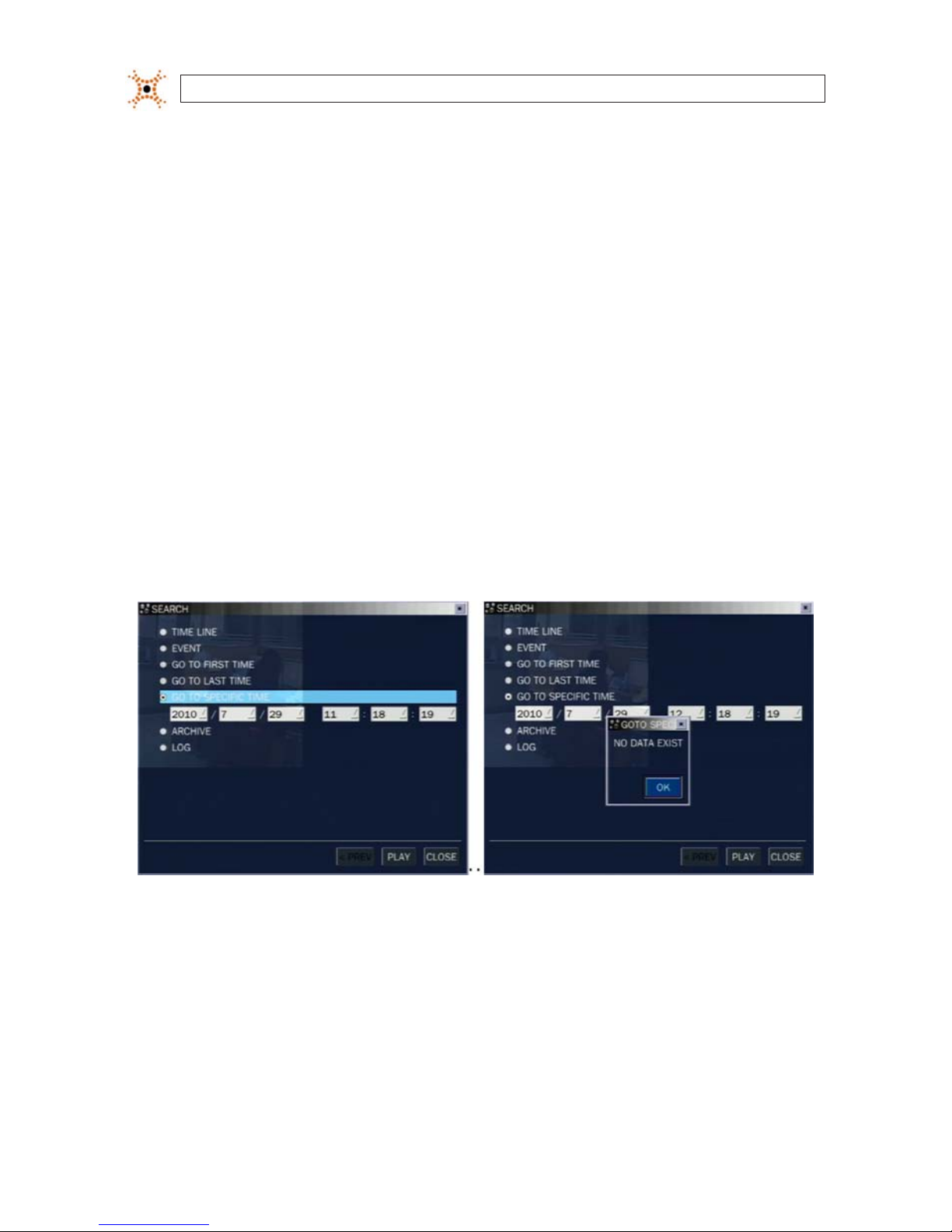
4.1.5 GO TO SPECIFIC TIME search
In the SEARCH window, select GO TO SPECIFIC TIME, then use the p, q, t, and u buttons to enter the starting time of the video
you want to play.
To stop playing video, press ESC. If no video was recorded at the time you entered, a NO DATA EXIST message will appear.
4.2 ARCHIVE search
To perform an archive search (search of recorded video), select ARCHIVE in the SEARCH window. A calendar window will open. The
highlighted days in the calendar window indicate that data recorded on those days was archived. Select the day when the data was
archived, then select NEXT.

37H.264 DVR User Manual
SECTION 4: LIVE, SEARCH, AND PLAYBACK
In the archive list, select the le entry you want to see, then select DISPLAY. In the ARCHIVE IMAGE window, select the media
location and format of the archive. To close the ARCHIVE IMAGE window, press ESC.
4.3 PLAY mode
Playing a recorded event changes the DVR mode from SEARCH to PLAY. While in PLAY mode, you can return to the SEARCH screen
by pressing the ESC button.
Playback controls are located at the bottom of the screen.

38
www.digiop.com
SECTION 4: LIVE, SEARCH, AND PLAYBACK
Table 17. Playback controls (PLAY Mode)
Icon Desc ription
Selec t to the previous menu s creen or search window, or exit f rom the menu.
t t
Selec t to rewind the recording. Select again to in crease the rew ind speed.
-- t
Jump/step back ward. The playb ack position moves 6 0 seconds back.
u / II
Selec t to play or pause a recording.
u --
Jump/step for ward. Playback posit ion moves 60 se conds ahead.
u u
Selec t to fast for ward the recording. Selec t again to increa se the fast forward speed.
Selec t to backup video.

39H.264 DVR User Manual
SECTION 5: PTZ CONTROL
SECTION 5
PTZ Control
To control the PTZ functions of the camera, select Camera PTZ on the OSD menu. Use the p, q, t, and u buttons to select the
channel of the PTZ camera and features you want to control.
Table 18. Button functions in PTZ control
Item Des cription
INITIALIZE Initialize the PTZ set tings of the selec ted camera.
PAN / TILT
Selec t PAN/TILT using the p q t and u button, t hen and press SEL. Adjus t the tilt (UP/
DOWN)/pan (LEFT/RIGHT) position using the p, q, t, and u buttons.
ZOOM / FOCUS
Selec t ZOOM/FOCUS using the p, q, t, and u but tons, then press SEL. Adjust the zoo m (UP/
DOWN)/fo cus (LEFT/RIGH T) position u sing the p, q, t, and u but tons.
OSD
Selec t OSD to enter the menu. Cont rol keys are Right, Lef t, UP, Down, Sele ct, Far (REW KEY), and
Near (FF KEY). Pre ss the ESC but ton to return to the previous menu. Press the PTZ bu tton to close
the OSD menu.
AUTOSCAN
Press t he right key (u) to star t auto scan. Pre ss the left ke y (t) to stop auto s can.
PRESE T
Selec t PRESET, then press th e left key (t). A number input wind ow will appear. Set the number (3
digit s) using the number key, then press the SEL to con rm the preset number for the c urrent position. Pr ess the right key (u) and enter the number (3 digit s) to go to the preset position. .
TOUR
Selec t TOUR and press t he right (u) key. A number inpu t window will open. Sele ct a number (1
digit) using a number key, then press SEL to start the tour. Pre ss the left (t) key to s top the tour.
Prese t the number of the tour gro up in the OSD menu.
NUMBER For the TOUR and PR ESET menu.
Press ESC to return to t he main menu.
The Preset, Tour, OSD, and Autoscan function are only available on some camera models.

40
www.digiop.com
SECTION 6: BACKUP
SECTION 6
Backup
Still images and video clips can be backed up in both Live mode and Playback mode, and written to a USB ash drive (with FAT32
format) or CD/DVD.
6.1 Still image backup onto USB ash drive
Still images can be captured and backed up onto the USB ash drive or CD/DVD while in Live mode or during video playback. To
initiate a backup, press the BACKUP button or select the BACK UP menu to launch the archive function.
1. If in Live mode, select the channel to backup the image from. The BACKUP window will open.
2. Select the media you want to save the image on. If you want to backup the image to a USB ash drive, insert the drive into
the USB port on the back or front of the DVR. If you want to backup to a CD or DVD, place a blank CD-R/W or DVD-R/W disk
into the DVD drive.
3. Select BACKUP. When the backup is complete, a message will appear. When the DVR backs up to a USB ash drive, it will
create a directory on the ash drive with a date-coded named in the format “YYYYMMDD” (ex. “20110210”) and write the
le there.
6.2 Video backup onto USB ash drive
Video can be archived onto the USB ash drive or CD/DVD while in playback mode. To perform the backup:
1. In playback mode, press the BACKUP button to launch the archiving function.
2. When the BACKUP window opens, select Video clip, then select Next.
3. In the BACKUP window, select the channel(s) you want to backup, the duration, and the le format (AVI or Huge Backup
[NFS]), then select Next.

41H.264 DVR User Manual
SECTION 6: BACKUP
4. Select the media you want to back the image onto. If you want to backup the image to a USB ash drive, insert the drive into
the USB port on the back or front of the DVR. If you want to backup to a CD or DVD, place a blank CD-R/W or DVD-R/W disk
into the DVD drive.
5. Select BACKUP. When the backup is complete, a message will appear. When the DVR backs up to a USB ash drive, it will
create a directory on the ash drive with a date-coded named in the format “YYYYMMDD” (ex. “20110210”) and write the
le there.
6.3 Copy still images or video from the ARCHIVE list
Video clips and images stored in the ARCHIVE list on your hard drive can be copied to a USB ash drive or a CD/DVD. To perform the
copy:
1. Use the p, q, t, u, and SEL buttons to open the SEARCH window and select ARCHIVE. A calendar window will open.
Dates highlighted in the calendar window indicate that archived data exists for that time.
2. In the calendar window, select a date, then select Next.
3. Scroll through the archive list and highlight the le of interest. Select DISPLAY.

42
www.digiop.com
SECTION 6: BACKUP
4. In the ARCHIVE IMAGED window, select the media (USB or CD/DVD-R). If you want to copy the le to a USB ash drive, insert
the drive into the USB port on the back or front of the DVR. If you want to backup to a CD or DVD, place a CD-R/W or DVDR/W disk into the DVD drive.
5. Select BACKUP to copy the le to the media drive.
6. When the backup is complete, select CLOSE button to return to the LOG list window.
6.4 Playing backed up video clips
Video clips are backed up from the DVR in AVI format. These les can be played in Microsoft® Windows® with Window Media®
Player and other players compatible with AVI formatted les.

43H.264 DVR User Manual
SECTION 7: FIRMWARE UPGRADE
SECTION 7
Firmware Upgrade
The rmware installed in your DVR will probably never need to be changed. If new rmware is released, however, upgrading the
rmware in your DVR may be recommended by DIGIOP.
The general instructions for upgrading rmware are included in this section. For additional information, specic instructions, and to
obtain a rmware upgrade le, contact DIGIOP Support at: 1.877.972.2522.
To upgrade the rmware in your DVR:
1. Obtain the rmware update le from DIGIOP Support. The rmware upgrade le is usually named:
“apph_xxxxxx.bin” where “xxxxxx” represents the revision level of the rmware.
2. Plug a USB ash drive into a PC and format it for FAT32, if necessary.
3. Create a new directory on the ash drive named “upgrade”.
4. Copy the rmware le to the upgrade directory on the ash drive.
5. Disconnect the ash drive from the PC and plug it into a USB port on the DVR.
6. Open the SETUP menu on the DVR, then open the SECURITY tab.
7. Select the User Password button.

44
www.digiop.com
SECTION 7: FIRMWARE UPGRADE
Submenu
Button
(Virtual
Keyboard)
8. In the USER PASSWORD window, select the USER ADMIN if not shown.
9. In the CURRENT eld, click the submenu button to open the virtual keyboard. Enter “12341234”, then select OK.
10. Return to the USER PASSWORD window and select OK. The DVR will restart and open a Diagnostics screen.
11. In the Diagnostic screen menu, select USB Upgrade.
NOTE
To exit the Diagnostics screen and restart the DVR, select Boot Application in the Diagnostic menu.
12. Follow the on-screen instructions to install the rmware upgrade. After the upgrade is completed, select Boot Application
to restart DVR.

45H.264 DVR User Manual
SECTION 8: UMS SINGLE CLIENT SOFTWARE
SECTION 8
UMS Single Client Software
UMS Single Client software is used to remotely monitor a single DVR. It can be used to display live images from your cameras, search
for and play back recorded data, monitor alarms, control PTZ devices, and capture and backup data.
NOTE
In a high bandwidth network, a maximum of four users can access one DVR simultaneously. In a low bandwidth network it is
recommended that only one user access the DVR at a time.
8.1 PC Requirements
For the UMS Single Client software, the minimum PC requirements are:
• CPU: Intel® Pentium® IV, 1.4 GHz or higher
• Memory: 512MB (1GB or larger is recommended.)
• VGA memory: 16 MB (64 MB or larger is recommended.)
• Resolution: 1024 x 768
• Supported operating systems: Microsoft® Windows® 2000, XP Professional, XP Home
• DirectX®: DirectX 8.1 or higher
8.2 Installing the UMS Single Client
1. Insert the provided CD in the CD drive. Open a le list of the CD, then double-click “UMSClient(xxxxxx).exe”
CD le list (typical)
2. After les are extracted, a Choose Destination Location window will open. Browse for the your preferred location, then click
“Next”.

46
www.digiop.com
SECTION 8: UMS SINGLE CLIENT SOFTWARE
3. Select the preferred program folder, then click “Next”. The setup status screen will open.
4. Select a Program Folder for the Start menu, then click Next. The UMS client will be installed and a UMS Client icon will
appear on the desktop.
5. Close the InstallShield window.
8.3 UMS Single Client initial display
To open the UMS Single Client, double-click the icon on the desktop, or open it through the Windows Start menu.

47H.264 DVR User Manual
SECTION 8: UMS SINGLE CLIENT SOFTWARE
Table 19. UMS Single Client window components
Button Function Description
WINDOW CONTROL
Buttons for expanding t he image to full screen (press ESC to re turn to
normal viewing), minimizing the window, expan ding window to full
screen, and closing the window.
DATE & TIME Displays the c urrent date and time.
CONNEC T/DISCONNECT Connect/disconnec t a DVR.
SEARCH Switches from Live mod e to Search mode.
KEYPAD
Selec t a channel. Click the channel button, or doub le-click the channel on
the Live view sc reen.
SPLIT-SCREEN MODE Selec t a split-screen mode 4 -, 9-, or 16-channel display.,
PAN/TILT/ZOOM/ FOCUS Control the PAN/TILT/ZOOM/FO CUS features on the remote camera.

48
www.digiop.com
SECTION 8: UMS SINGLE CLIENT SOFTWARE
Button Function Description
FUNCTIONS
CAPTURE: Capture a still image of the s creen.
PLAY/PAUSE Play/freeze live vide o
BACKUP: Initiate backup oper ation (record on/o).
PRESET: Select c amera position pre set.
SETUP: Open th e setup menus.
ALARM: The ON/O FF button of the alarm o utput of the DVR . When an
alarm is active, this button is red.
HDD USAGE DVR HDD space used Indicator.
NETWORK BANDWIDTH Shows the transfer red frames and net work bandwidth.
AUDIO Adjust the volume. Audio is on or muted by clicking the speaker icon.
LOG WINDOW
8.4 Setup
The UMS Single Client includes several setup options, including presets for the DVRs you want to connect to. To open the setup
menus, click the Setup button.
8.4.1 General Setup
When the Setup menu is opened, the General options are displayed.
General options include:
• Security Option: Set a password for security options. If set, you must enter the password when accessing any of the security
functions.

49H.264 DVR User Manual
SECTION
• Save Path: Specify the location backup and still image captures are saved.
• Automatic Reconnection: If a user selects this function, the client will automatically try to connect to the previously
connected IP address if the network connection is lost.
• Display Network Statistics: The client can display network status, bit rate and frame rate.
• Time Format: Select the format for displaying the time.
After entering all elds in the Site Additions window, click OK to save your entries and exit the Setup menus.
8.4.2 Site Setup
To open the Site menu, click the Site entry in the left frame of the Setup window.
Initially, no site (DVR) is listed. To add a site, click the Addition button.

50
www.digiop.com
SECTION 8: UMS SINGLE CLIENT SOFTWARE
In the Site Addition menu, enter:
• Model: Select N Series DVR, HD DVR if you are connecting to a BLK-DH200400D, BLK-DH200800D, or BLK-DH201600D DVR
• Site Name: Enter an appropriate name for the DVR you will connect to.
• IP Address: Enter the IP address and web port number (if other than 80).
• Port No: Enter the port number for the DVR. The default DVR port number is 5445.
• ID: Enter your login ID (login name).
• PASSWORD: Enter the password associated with the login ID. The default login ID and password are Admin and 1111.
• Channels: Enter the number of channels supported by your DVR (4, 8, or 16).
After entering all elds in the Site Additions menu, click OK to save your entries and exit the Setup menus.
8.4.3 Event Setup
To open the Event menu, click the Event entry in the left frame of the Setup window. The Event menu allows you to congure how
the client will display and log event information received from the DVR.

51H.264 DVR User Manual
SECTION 8: UMS SINGLE CLIENT SOFTWARE
In the Event Setup menu, set the following:
• Log Path: Click the browse button to identify where event log les are saved.
• Log Size: Set the maximum size in megabytes of the event log le space.
• Event Log: For each event type, select the checkbox to save the event data in the log le.
• Event Icon: For each event type, select the checkbox to display the event on live video.
• Event List: For each event type, select the checkbox to show the event in the Event List in live mode.
After entering all elds in the Site Additions menu, click OK to save your entries and exit the Setup menus.
8.4.4 Event Search Setup
The Event Search window is used to display a list of the logged events that occurred during a specied time period. Use the
dropdown lists to choose the From and To times, then browse to the location of the log le. To save the list of events to another le,
click Save. An event timestamp can be used to easily nd the video recordings of the event.

52
www.digiop.com
SECTION 8: UMS SINGLE CLIENT SOFTWARE
After entering all elds in the Event Search menu, click OK to save your entries and exit the Setup menus.
8.4.5 Record Setup
To open the Record menu, click the Record entry in the left frame of the Setup window. The Record menu allows you to congure
the conditions that trigger live video recording.
In the Record menu, set the following:
• Record Condition: Select Always or Event, then Auto record.
• Event: If Event was selected as the Record Condition, select the type of event and the duration of the recording.
• Channels: Select the channels to be recorded during the conditions selected above. |
After entering all elds in the Record menu, click OK to save your entries and exit the Setup menus.
8.4.6 Record Disk Setup
To open the Record Disk menu, click the Disk entry in the left frame of the Setup window. The Disk menu allows you to select the
location where recorded data is saved, and the amount of space on the disk to allocate for recordings.

53H.264 DVR User Manual
SECTION 8: UMS SINGLE CLIENT SOFTWARE
In the Disk menu, select the storage drive from the dropdown list, then enter the size of the storage buer in megabytes. Choose
either Replace oldest les or Stop recording when the disk is full. Click OK to save your entries and exit the Setup menus.
8.4.7 Language Setup
To open the Language menu, click the Language entry in the left frame of the Setup window. Choose the preferred on-screen
language from the dropdown list, then click OK to save the selection and close the Setup menu.
8.5 Connecting to a DVR
To connect to a DVR, click the Connect button. The Connect dialog window will open. The Connect window is lled by the entry
made in the Setup Site menu.
In the Connect window, use the dropdown lists to select the DVR you want to connect to, then click OK. A Live view window from
your DVR will be displayed.

54
www.digiop.com
SECTION 8: UMS SINGLE CLIENT SOFTWARE
8.5.1 Bidirectional Audio
The UMS Single Client supports bidirectional audio between the client PC and a DVR. To use bidirectional audio, the client PC must
have a microphone and speakers. At the DVR, connect a microphone to the audio-in connectors, and a pair of amplied speakers to
the audio-out connectors.
8.6 Remote Search mode and functions
After connecting to the DVR, the UMS Single Client can be used to search for and playback recorded video. Video clips can then be
backed up to a USB drive or local hard disk. To open the Search screen, click the Search button.

55H.264 DVR User Manual
SECTION 8: UMS SINGLE CLIENT SOFTWARE
Table 20. UMS Single Client Search window components
Button Function Description
WINDOW CONTROL
Buttons for expanding t he image to full screen (press ESC to re turn to
normal viewing), minimizing the window, expan ding window to full
screen, and closing the window.
DATE & TIME Displays the c urrent date and time.
CONNEC T/DISCONNECT Connect/disconnec t network connec tion.
LIVE Switche s from search mode to live mode.
KEYPAD
Selec t a channel. Click the channel button, or doub le-click the channel on
the live view screen.
SPLIT-SCREEN MODE Selec t a split-screen mode 4 -, 9-, or 16-channel display.,

56
www.digiop.com
SECTION 8: UMS SINGLE CLIENT SOFTWARE
Button Function Description
CALENDAR
In the calendar f rame, dates wi th recorded video are colored in light blue.
Click th e date of the recorded video you w ant to nd or play.
FUNCTIONS
CAPTURE: Capture a still image of the s creen/camera.
MARK IN: Set the s tart time at the marker position
MARK OUT: Set the end t ime at the marker position
SETUP: Display t he setup scre en of the network viewer.
BACKUP: B ackup the video clip f rom MARK IN time to MARK OUT time
HDD USAGE DVR HDD space used Indicator.
AUDIO Adjust the volume. The audio is on or muted by clicking the speaker icon.
TIMELINE Bar
Display s a timeline for the date selec ted in the calendar fr ame. Time spans
when video is re corded are marked in blue. To expand the display for an
hour when vide o was recorded, drag th e marker to the hour you want to
expand, then click the 0 - 60 but ton (locate d below the time line).
PLAYBACK BUTTONS
Use the playbac k buttons to control v ideo playback. The playbac k buttons
are labeled wit h the standard icons us ed for video play control.
8.6.1 Searching for and playing video recorded by the DVR
1. At the UMS Single Client, connect to the DVR.
2. Press the SEARCH button. The client will change from live mode to search mode.
3. In the calendar frame, click the date when video was recorded.
4. Drag the marker on the timeline to the time at which you want to play recorded video. To expand the hour within which the
marker lies, click the 0 - 60 button below the time line.
Marker
5. Click the PLAY button to begin playing video at the marker position.

57H.264 DVR User Manual
SECTION 8: UMS SINGLE CLIENT SOFTWARE
8.6.2 Backing up video from the DVR on the UMS Single Client PC
Video recorded in the DVR can be backed up on the PC where the UMS Single Client is installed. Video clips are saved in AVI format.
1. At the UMS Single Client, connect to the DVR.
2. Click the SEARCH button. The client will change from live mode to search mode.
3. In the calendar frame, click the date when the video was recorded.
4. Drag the marker on the timeline to the time at which you want to play recorded video.
Marker
To expand the hour within which the marker lies, click the 0 - 60 button below the time line.
5. Play the video to determine the time where you want to start backing up a clip, then pause the playback and click the MARK
IN button.
6. Continue playing the video to determine the time where you want to end the clip, then stop the playback and click the
MARK OUT button. The time span between the MARK IN and MARK OUT times will be highlighted in dark green.
Mark In Mark Out
7. Click the PLAY button to view the video clip you marked.

58
www.digiop.com
SECTION 8: UMS SINGLE CLIENT SOFTWARE
8. To backup the video clip you marked, stop the video playback, then press the BACKUP button. The Backup menu window
will open.
9. In the Backup menu, select the options you want, then click OK.
10. A pop-up window will appear when the backup operation is complete. Click OK to close the backup operation.
NOTE
Video backup can take several minutes to complete, depending on the number of channels selected and the duration of the clip.

59H.264 DVR User Manual
SECTION 8: UMS SINGLE CLIENT SOFTWARE
8.6.3 Image capture
A still image of a screen can be captured in either Live mode or Search mode, then saved as a BMP or JPEG le. To capture a still
image of the screen, click the Capture button. A Capture menu will open.
In the Capture menu, select the options you want, then click OK. An image of the screen will be saved at the location you specied.

60
www.digiop.com
SECTION 9: UMS MULTI CLIENT SOFTWARE
SECTION 9
UMS Multi Client Software
UMS Multi Client software can monitor several DVRs (sites) simultaneously. It can display to up 256 live video channels on one
screen, playback video clips, control PTZ cameras, monitor alarms, and be congured with 2-way audio communication through the
DVR.
NOTE
In a high bandwidth network, a maximum of four users can access one DVR simultaneously. In a low bandwidth network it is
recommended that only one user access the DVR at a time.
9.1 PC Requirements
For the UMS Multi Client software, the minimum PC requirements are:
• CPU: Intel® Pentium® IV, 2GHz or faster
• Memory: 512MB (1GB or larger is recommended.)
• VGA memory: 16MB (64MB or larger is recommended.)
• Resolution: 1024 x 768
• Disk space: 1GB
• Supported operating systems: Microsoft Windows 2000, XP Professional, XP Home, Vista (Some versions of Windows
Vista are incompatible. Contact DIGIOP for more information.)
• Network: 10/100BaseT network
• DirectX: DirectX 8.1 or higher
9.2 Installing the UMS Multi Client
1. Insert the provided CD in the CD drive. Open a le list of the CD, then double-click “UMSMClient(xxxxxx).exe”
CD le list (typical)
2. After les are extracted, a Choose Destination Location window will open. Browse for the your preferred location, then click
“Next”.

61H.264 DVR User Manual
SECTION 9: UMS MULTI CLIENT SOFTWARE
3. Select the program folder and click “Next”. The setup status screen is displayed.
4. Select a Program Folder for the Start menu, then click Next. The UMS Multi Client will be installed and a “UMS Multi Client”
icon will be displayed on the desktop.
5. Close the InstallShield window.
9.3 UMS Multi Client initial display
To open the UMS Multi Client, double click the icon on the desktop or open it through the Windows Start menu.

62
www.digiop.com
SECTION 9: UMS MULTI CLIENT SOFTWARE
Table 21. UMS Multi Client window components
Button Function Description
WINDOW CONTROL
Buttons for expanding t he image to full screen (press ESC to re turn to normal
viewing), minimizing the window, expanding window to f ull screen, and closing
the window.
SEARCH LOCAL Search for video les recorded on the loc al PC.
SEARCH REMOTE Search for video le s recorded on the DVR.
SITE CONT ROLS
Applie s control to site s selected in the site list below. These icons link to: ref resh
thumbnail, site addition, site delete, net nder (site modif y)
SITE LIS T
List of sites ad ded to the DVR. The site list appears in the pane b eneath the site
contro ls icons.
CONNEC T Click to co nnect to site s selected in the frame above.
DISCONNECT Click to disco nnect to site s selected in the frame above.
SETUP Open the setup menus
CAPTURE Capture a s till image of the screen.

63H.264 DVR User Manual
SECTION 9: UMS MULTI CLIENT SOFTWARE
Button Function Description
EVENT LIST Opens the list of events lo gged by the UMS Multi Client.
PAUSE Freezes the screen
ALARM
RECORD Enable/disable recordin g of live video.
SPEAKER, MICROPHO NE Controls for adjusting the volume of t he speaker and micropho ne.
PTZ FOCUS/ZOOM Buttons for contro lling PTZ camera focu s and zoom (in/out).
PTZ PAN/T ILT
Buttons for controlling PT Z camera pan (t u) and tilt (p q).
CHANNEL SPLIT Use to selec t the number of channels (1/4/9/16) shown on the sc reen.
SITE SPLIT Use to select the numb er of DVRs (1/4/9/16) shown on the sc reen.
9.4 Setup
The UMS Multi Client includes several setup options. To open the setup menus, click the Setup button.
9.4.1 General Setup
When the Setup menu is opened, the General options are displayed.

64
www.digiop.com
SECTION 9: UMS MULTI CLIENT SOFTWARE
General options include:
• Security Option: Set a password for security options. If set, you must enter the password when accessing any of the security
functions.
• Save Path: Specify the location backup and still image captures are saved.
• Automatic Reconnection: If a user selects this function, the client will automatically try to reconnect to the previously
connected IP address if the network connection is lost.
• Display Network Statistics: The client can display network status, bit rate and frame rate.
• Time Format: Select the format for displaying the time.
After entering all elds in the Site Additions window, click OK to save your entries and exit the Setup menus.
9.4.2 Event Setup
To open the Event menu, click the Event entry in the left frame of the Setup window. The Event menu allows you to congure how
the client will display and log event information received from the DVR.

65H.264 DVR User Manual
SECTION 9: UMS MULTI CLIENT SOFTWARE
In the Event Setup menu, set the following:
• Log Path: Click the browse button to identify where event log les are saved.
• Log Size: Set the maximum size in megabytes of the event log le space.
• Event Log: For each event type, select the checkbox to save the event data in the log le.
• Event Icon: For each event type, select the checkbox to display the event on live video.
• Event List: For each event type, select the checkbox to show the event in the Event List in live mode.
After entering all elds in the Site Additions menu, click OK to save your entries and exit the Setup menus.
9.4.3 Event Search Setup
The Event Search window is used to display a list of the logged events that occurred during a specied time period. Use the
drop-down lists to choose the From and To times, then browse to the location of the log le. To save the list of events to another
le, click Save. An event timestamp can be used to easily nd the video recordings of the event.
After entering all elds in the Event Search menu, click OK to save your entries and exit the Setup menus.
9.4.4 Record Setup
To open the Record menu, click the Record entry in the left frame of the Setup window. The Record menu allows you to select the
conditions in which live video from the cameras is recorded.

66
www.digiop.com
SECTION 9: UMS MULTI CLIENT SOFTWARE
In the Record menu, set the following:
• Record Condition: Select Always or Event, then Auto record.
• Event: If Event was selected as the Record Condition, select the type of event and the duration of the recording.
• Channels: Select the channels to be recorded during the conditions selected above.
After entering all elds in the Record menu, click OK to save your entries and exit the Setup menus.
9.4.5 Record Disk Setup
To open the Record Disk menu, click the Disk entry in the left frame of the Setup window. The Disk menu allows you to select the
location where recorded data is saved, and the amount of space on the disk to allocate for recordings.
In the Disk menu, select the storage drive from the dropdown list, then enter the size of the storage buer in megabytes. Choose
either Replace oldest les or Stop recording when the disk is full. Click OK to save your entries and exit the Setup menus.

67H.264 DVR User Manual
SECTION 9: UMS MULTI CLIENT SOFTWARE
9.4.6 OSD Setup
To open the OSD (On Screen Display) menu, click the OSD entry in the left frame of the Setup window. The OSD menu allows you to
select the kinds of information and events messages that appear on the scree. Each site you connect to can be congured dierently.
After selecting the preferred options in the OSD menu for each site, click OK to save your entries and exit the Setup menus.
9.4.7 Language Setup
To open the Language menu, click the Language entry in the left frame of the Setup window. Choose the preferred on-screen
language from the dropdown list, then click OK to save the selection and close the Setup menu.
9.5 Connecting to a DVR
To connect to a DVR for the rst time:
1. Click the Site Addition button. The Site Addition dialog window will open.

68
www.digiop.com
SECTION 9: UMS MULTI CLIENT SOFTWARE
Site Addition
Connect
2. In the Site Addition menu, enter:
— Model: Select N Series DVR, HD DVR if you are connecting to a BLK-DH200400D, BLK-DH200800D, or
BLK-DH201600D DVR
— Site Name: Enter an appropriate name for the DVR you will connect to.
— IP Address: Enter the IP address and web port number (if other than 80).
— Port No: Enter the port number for the DVR. The default DVR port number is 5445.
— ID: Enter your login ID (login name).
— PASSWORD: Enter the password associated with the login name. The default login ID and password are Admin and
1111.
3. After entering all elds in the Site Additions menu (see above) click OK to save your entries. An entry for the DVR you
added will appear in the site list frame (below the Site Addition icon).
4. Click the checkbox in the entry you added to the site list .
Select
Checkbox
5. Click the Connect button to connect to the DVR.

69H.264 DVR User Manual
SECTION 9: UMS MULTI CLIENT SOFTWARE
UMS Multi Client DVR Live View
9.5.1 Bidirectional Audio
The UMS Multi Client supports bidirectional audio between the client PC and a DVR. To use bidirectional audio, the client PC requires
connections for a microphone and speakers. At the DVR, connect a microphone to the audio-in connectors, and a pair of amplied
speakers to the audio-out connectors.
9.5.2 Capture
A still-image of a screen can be captured in either Live mode or Search mode and saved as BMP or JPEG le. To capture a still image
of the screen, click the Capture button. A Capture menu will open.
In the Capture menu, select the options you want, then click OK. An image of the screen will be saved at the location you
specied. By default, captured images are saved in the directory specied in the Setup / General menu. However, the Save Path
can be changed in the Capture menu if necessary.

70
www.digiop.com
SECTION 9: UMS MULTI CLIENT SOFTWARE
9.5.3 Record
Video recording of the live screen can be manually started and stopped by clicking the Record button. When video is being
recorded, the Record button is highlighted blue. To stop recording, click the Record button again. By default, recorded video is
saved in the path specied in the Setup / General menu.
9.6 Remote playback and backup
The UMS Multi Client can be used to search for and playback video clips in the DVR. Video clips can then be backed up to a local USB
drive or disk.
NOTE
The Event List may provide valuable information on when alarms and other events occurred. To open the Event List, click the
Events List button.
9.6.1 Remote playback
To search for and recorded video from the DVR:
1. At the UMS Multi Client, connect to the DVR.
2. Click the Remote playback button. The client will change from live mode to the Search mode.

71H.264 DVR User Manual
SECTION 9: UMS MULTI CLIENT SOFTWARE
Table 22. UMS Multi Client search window components
Button Function Description
FUNCTIONS
SETUP: Opens t he Setup menu
CAPTURE: Capture a still image of the s creen/camera.
EVENT LIST: Displays logge d DVR events.
MARK IN: Set the s tart time at the marker position
MARK OUT: Set the end t ime at the marker position
BACKUP: O pens a menu to backup the sect ion of video between the MARK IN
time and M ARK OUT time
AUDIO Adjust the volume. The audio is o n or muted by clicking the speaker icon.
MULTI-DVR DISPLAY
SPLIT-SCREEN
MODE
Display multiple DVRs
Selec t a split-scre en mode 1-, 4-, 9-, or 16- channel display.,
KEYPAD
Selec t a channel. Click the channel button, or doub le click the channel on the
live view screen.
CALENDAR
In the calendar f rame, days wit h recorded video are co lored in light tan. Click
the date of the recorded video you want to nd or play. The date colored blue
is the date date selected; the timeline shows when dat a was recorded on
that date.
TIMELINE Bar
Display s a timeline for the date selec ted in the calendar fr ame. Time spans
when video is re corded are marked in blue. To expand the display for an hour
when video was r ecorded, drag the mar ker to the hour you want to expand,
then click the 0 - 60 but ton (located below the time lin e).
PLAYBACK BUTTONS
Use the playbac k buttons to control v ideo playback. The playbac k buttons are
labele d with the standard icons use d for video play control.
3. Select the DVR (checkbox) of the unit you want to see recorded video from.
4. In the calendar frame, click the date when the video of interest was recorded.
5. Drag the marker on the timeline to the time at which you want to play recorded video. To expand the hour within which the
marker lies, click the 0 - 60 button above the timeline.
Marker
6. Click the PLAY button to begin playing video at the marker position.

72
www.digiop.com
SECTION 9: UMS MULTI CLIENT SOFTWARE
9.6.2 Backing up video from the DVR on the UMS Multi Client PC
Video recorded in the DVR can be backed up on the PC where the UMS Multi Client is installed. Video clips are saved in AVI or NFS
format.
1. At the UMS Multi Client, connect to the DVR.
2. Click the Remote playback button. The client will change from Live mode to the Search mode.
3. Select the DVR (checkbox) of the unit you want to see video from.
4. In the calendar frame, click the date when the video of interest was recorded.
5. Drag the marker on the timeline to the time at which you want to play recorded video.
Marker
To expand the hour within which the marker lies, click the 0 - 60 button above the timeline.

73H.264 DVR User Manual
SECTION 9: UMS MULTI CLIENT SOFTWARE
6. Play the video to determine the time where you want to start backing up a clip, then stop the playback and click the MARK
IN button.
7. Continue playing the video to determine the time where you want to end the clip, then stop the playback and click the
MARK OUT button. The time span between the MARK IN and MARK OUT times will be highlighted in dark green.
Mark In Mark Out
8. To backup the video clip, click the BACKUP button. The Backup menu window will open.
9. In the Backup menu, select the options you want, then click OK.
10. A pop-up window will appear when the backup operation is complete. Click OK to close the Backup operation.
NOTE
Video backup can take several minutes to complete, depending on the number of channels selected and the duration of the clip.

74
www.digiop.com
SECTION 9: UMS MULTI CLIENT SOFTWARE
9.7 Local playback
Use the Local Playback feature to play video recorded by the UMS Multi Client record feature and saved on the local PC. To play these
recordings:
1. Click the Local playback button. The playback window will open.
2. In the directory frame, select the site(s) you want to play recordings of. The calendar will indicate which days have recorded
video les on the local PC.
3. Click the day of the recording you want to play, then drag the marker to the time when video was recorded.
Click the 0 - 60 button above the timeline to expand the time scale.

75H.264 DVR User Manual
SECTION 9: UMS MULTI CLIENT SOFTWARE
4. Use the video play control buttons above the timeline to play the video.
9.7.1 AVI backup during playback
Video recorded by the UMS Multi Client is saved on the local PC in .NDB le format. To save the video clip of a recorded le in .AVI
le format (compatible with most media players), perform a backup operation:
1. Play the video le that contains the segment you want to save in .AVI format. (See Local playback above.)
2. Play the video to determine the time where you want to start backing up a clip, then stop the playback and click the MARK
IN button.
3. Continue playing the video to determine the time where you want to end the clip, then stop the playback and click the
MARK OUT button. The time span between the MARK IN and MARK OUT times will be highlighted in dark green.
Mark In Mark Out
4. To backup the video clip, press the BACKUP button. The Backup menu window will open.

76
www.digiop.com
SECTION 9: UMS MULTI CLIENT SOFTWARE
5. In the Backup menu, select the options you want, including the AVI le format, then click OK.
6. A pop-up window will appear when the backup operation is complete. Click OK to close the Backup operation.
NOTE
Video backup can take several minutes to complete, depending on the number of channels selected and the duration of the clip.
NOTE
If your media player cannot play the le backed-up in AVI le format, it probably doesn’t use the correct CODEC. Update your
H.264 CODEC and retry playing the le.

77H.264 DVR User Manual
SECTION 10: WEBVIEWER
SECTION 10
WebViewer
WebViewer is a Microsoft Internet Explorer® (IE) browser based DVR administrative tool. It is embedded in the DVR and loaded into
the browser when the DVR is accessed. The DVR can be accessed locally (on the same local network), or from a connection to the
Internet (remotely), depending on the network conguration. The URL (internet address) of the DVR is dierent depending the path
used to connect to it.
If your computer is on the same local network as the DVR you are accessing, the URL is the IP address shown in the DVR System
Information window. In the example shown below, the URL is the IP ADDRESS: 192.168.5.3.
If you are accessing your DVR remotely, your DVR may be addressed as a port forwarded through the router or device that connects
the network with the DVR to the Internet, or through an established DDNS web service connection such as WWW.OKDDNS.COM.
Refer to WWW.OKDDNS.COM for more information.
10.1 Connecting to the DVR with IE
After your DVR is setup on a local LAN, use IE to connect to it to verify the DVR connectability. This connection increases exibility for
monitoring and conguring your security system.
Before you can connect to the DVR with IE, the (default) security settings in IE are modied slightly to allow it to install an software
from the DVR.
1. At your PC, load IE.
2. Open the IE Tools pull-down menu and select Internet Options. Click the Security tab.

78
www.digiop.com
SECTION 10: WEBVIEWER
3. Click the Custom Level... button. In the Settings list, change the following settings from Disable to Prompt:
Download unsigned ActiveX controls
Initialize and script ActiveX controls not marked as safe for scripting
Click OK, then click YES in the Warning window.

79H.264 DVR User Manual
SECTION 10: WEBVIEWER
In the Internet Options window, click Apply, then click OK to close the window.
NOTE
If your computer operating system is Windows Vista or Windows 7, User Account Control can interfere with the normal
operation of the DVR user interface. To disable UAC, open the Control Panel > User Account > User Account window, clear the
Use User Account Control (UAC) to help protect your computer check box, then click OK.
A computer restart may be required.
4. In the IE URL eld, enter the IP address assigned to your DVR. Using the example shown above, enter:
192.168.5.3
5. If a message appears to load the Nadatel-WebViewer, click Install. Follow the prompts to Install the program.
After the WebViewer loads, the Connect screen will be available.

80
www.digiop.com
SECTION 10: WEBVIEWER
WebViewer
Status
Frame
WebViewer
View
Screen
Table 23. WebViewer Live window components
Button Func tion Descr iption
TIMES TAMP
Times tamp window. When WebViewer is not connected, it shows the P C time. When
WebViewer is connec ted and showing live video, it indicates the DVR timestamp.
When WebViewer is play ing video, it is the time stamp of the video frame.
CONNEC T / DISCONNECT Used to initiate a connection to a DVR, or disconnec t from a DVR.
SEARCH / LIVE Used to s witch between the search window and the live mode window.
CHANNEL SELEC T Used to selec t and display one c hannel.
SPLIT SCREEN SELECT Used to select the scre en split: 2x2, 3x3, 4x4
PAUSE / CAPTUR E
PAUSE: use to f reeze the screen in live mode, or fre eze playback.
CAPTURE: use to save a snapshot of the current screen.

81H.264 DVR User Manual
SECTION 10: WEBVIEWER
Button Func tion Descr iption
PTZ DIRECTIONAL
CONTRO l
Used to co ntrol the dire ction of the selec ted PTZ camer a.
MOTE Us e to mute audio during live mode or playbac k.
ZOOM / FOCUS Use to control the zoom and f ocus of the selected PTZ camera.
SETUP Use to o pen the Setup menu window.
6. Click the Connect button. A Connect Webpage Diaglog menu window will open.
In the Webpage Dialog menu, enter:
— Server address: For access across a local network (WebViewer PC on the same subnet as the DVR), use the DVR IP
address. For access from the internet, use the DDNS URL (if available) or router/modem IP address with forwarded
port number.
— Port: Port number of the DVR (default = 5445)
— ID: Username. The default username for the DVR is Admin.
— Password: Password for the user ID. For ID Admin, the default password is 1111.
7. Click Connect to connect to your DVR. After connecting to the DVR, the connection status will appear in the Status frame,
and the DVR camera views will appear in the view screen.

82
www.digiop.com
SECTION 10: WEBVIEWER
10.2 Setup
The Setup feature enables you to congure your DVR through WebViewer. The Setup menu system includes the following
submenus: Display, Record, Device, Storage, System, Security, and Network. Components in these submenus are similar to those in
the DVR SETUP submenus (refer to Section 3 for denitions).
To enter the Setup menus after connecting to your DVR, click the Setup button. To enter a submenu, click the submenu name listed
down the left side of the screen. To exit the Setup menus, click Viewer in the upper-right corner of the screen.
10.2.1 Setup Display
Use the Display submenu to setup the sequential viewing of the channel and adjust the video quality of the display.

83H.264 DVR User Manual
SECTION 10: WEBVIEWER
10.2.2 Setup Record
Use the Record submenu to setup the recording mode for each camera channel.
10.2.3 Setup Device
Use the Device submenu to setup the Device, Alarm out, PTZ, and Spot Out conguration. To enter the device submenus, click the
submenu entry under Device.
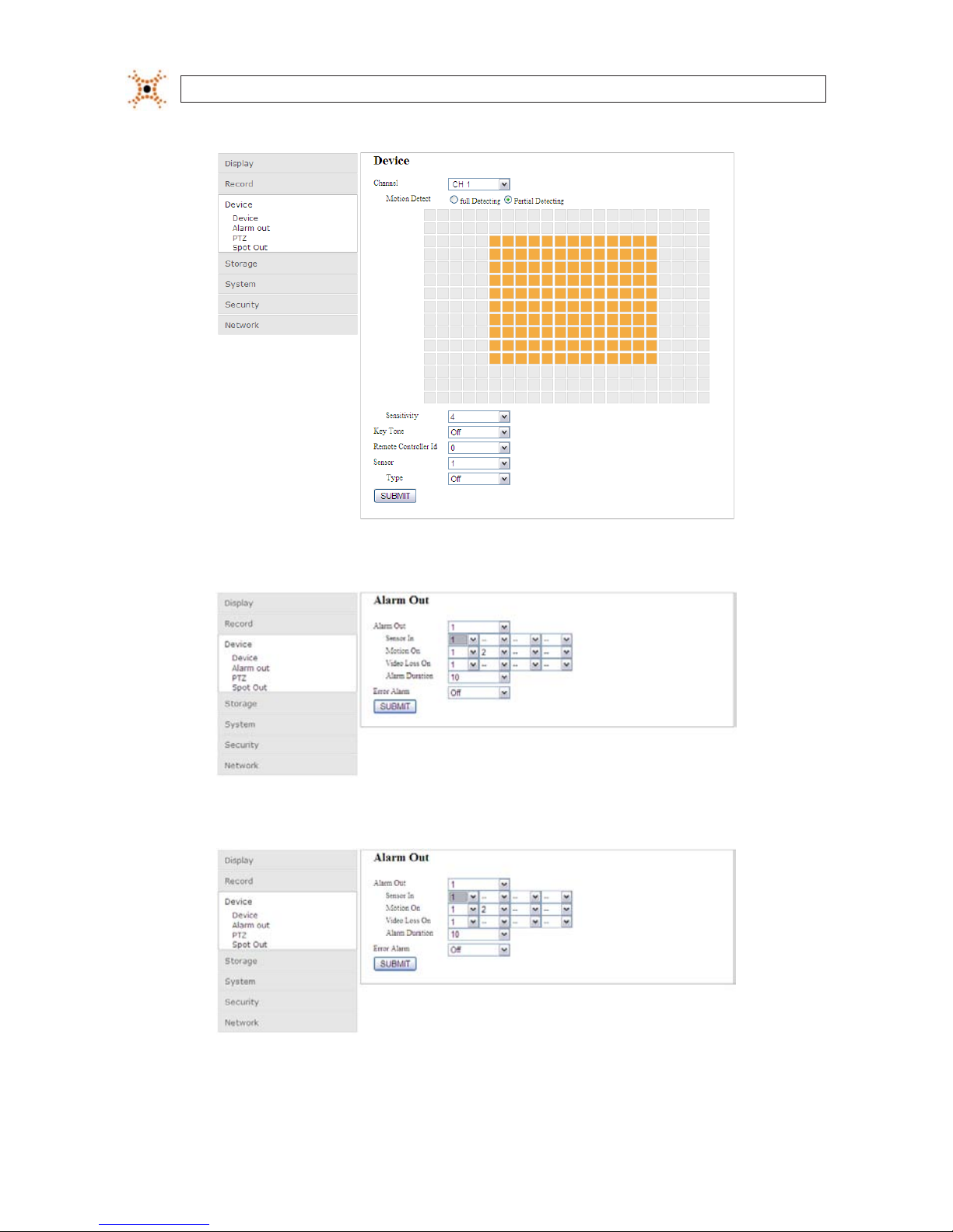
84
www.digiop.com
SECTION 10: WEBVIEWER
Device - Device submenu
Device - Alarm Out submenu
Device - PTZ submenu

85H.264 DVR User Manual
SECTION 10: WEBVIEWER
Device - Spot Out submenu
10.2.4 Setup Storage
Use the Storage submenu to setup the recording conguration of the DVR HDD.
10.2.5 Setup System
Use the System submenu to setup the system ID and access control, Date / Time, Send Email conguration, and NTP server access
credentials. To enter the System submenus, click the submenu entry under System.
System - System submenu

86
www.digiop.com
SECTION 10: WEBVIEWER
System - Description submenu
System - Date / Time submenu
System - Send Email submenu

87H.264 DVR User Manual
SECTION 10: WEBVIEWER
System - NTP submenu
10.2.6 Setup Security
Use the Security submenu to setup the user IDs, passwords, and permissions. To enter the Security submenus, click the submenu
entry under Security.
Security - User Authentication submenu
Security - User Password submenu

88
www.digiop.com
SECTION 10: WEBVIEWER
10.2.7 Setup Network
Use the Network submenu to setup the Network IP address, subnet, DNS/DDNS conguration, and ports assigned to the DVR.
Network - Network submenu
Network - Port submenu
10.3 DVR Search
In Search mode, you can watch video recorded by your DVR, backup video clips, and capture still images from recorded video. To
switch to Search mode, click the Search button on the Live mode display.

89H.264 DVR User Manual
SECTION 10: WEBVIEWER
WebViewer Search window
Table 24. WebViewer Search window components
Button Function Description
TIMES TAMP
Times tamp window. When WebViewer is not connected, it shows the P C time.
When WebViewer is connected and showing live video, it indicate s the DVR
times tamp. When WebViewer is in search mode or playing vide o, it shows the
times tamp of the vide o frame.
DISCONNECT Used to initiate a connect ion to a DVR, or disconnec t from a DVR.
LIVE / SEARCH Used to switch f rom the search mode window and t he live mode window.
CHANNEL SELEC T Used to s elect and display one c hannel.
SPLIT SCREEN SELECT Used to select the screen split : 2x2, 3x3, 4x4
BACKUP / C APTURE
BACKUP: use to bac kup recorded video.
CAPTURE: use to save a snapshot of the current screen.

90
www.digiop.com
SECTION 10: WEBVIEWER
Button Function Description
PLAY / STOP CONTROl
Used to play and pause video playback. Video is played star ting at the position of
the timeline marker. .
PLAYBACK MOTION
CONTROL
Used to co ntrol the playb ack of recorde d video from the position of the marker on
the timeline. Button function is (lef t to right, upper row to lower row): Fo rward,
Next frame, Forward j ump, Review, Previous frame, and Rewind jump.
CALENDAR
On the calendar frame, video was recorded on days co lored blue. The day sele cted
is highlighted.
TIMELINE The timeline shows fo r each channel when vide o was recorded o n the day selec ted.
10.3.1 Playing recorded video
1. Connect to the DVR (see above).
2. If WebViewer is in Live mode, slick Search to open the Search window.
3. In the calendar frame, click the day when the video you want to play was recorded. Sections of the timeline highlighted in
red indicate that live video was recorded on that channel at that time.
Marker Recorded Video Available
4. On the timeline, drag the marker to the time at which you want to play video, then click Play. The exact time position of the
marker is shown in the upper-left corner of the Search window.
5. To stop playing the video, click Stop.
10.4 Backup recorded video
Video clips (sections of video tracks) can be backed up and saved for playback on other devices. To backup a video clip, rst
determine the start time (From), the end time (To), and the channel of the recorded video you want to backup.

91H.264 DVR User Manual
SECTION 10: WEBVIEWER
1. Playback the recorded video you want to backup.
2. While watching the video, determine the exact starting timestamp and ending timestamp of the video clip you want to
backup.
3. Click Stop to stop the video playback.
4. Click Backup to open the backup menu. In the Backup window, edit the From (starting timestamp), To (ending
timestamp), and File (save to location) elds as needed.
Select the Channel of the video from the dropdown list, then click Ok to begin the backup operation. A progress bar will
appear showing the status of the backup. Allow the backup operation to complete before continuing.
5. To play the backed-up video le, open the le in an .AVI le compatible video player.
10.4.1 Capture
A snapshot of the screen image can taken in live mode, during pause, in playback mode, or when video playback is stopped. To take
a snapshot:
1. When connected to your DVR, click Capture. The parameter screen will open.
2. Click Ok. A snapshot of the screen image will be saved in .BMP format.

92
www.digiop.com
SECTION 11: SPECIFICATIONS
SECTION 11
Specications
Table 25. Specications
ITEM BLK-DH200 400D BLK-DH200800D BLK-DH201600D
Video
Input
Channel, Input Level 4 channel, composite 8 channel, composite 16 channel, composi te
Signal Format NTS C
Video Loss Che ck Yes
Output
Main Monitor Ou tput 1 VGA (1024 x 768 or 1280 x 1024 @ 60Hz),
Signal Format VGA
Spot 2
Audio
Input / Output 4 channel line input / 1 chann el line output
Audio CODEC G.711
Alarm
Sensor Input (N C/NO selec table) 4 channel (NC/N O selectab le)
Alarm Ou tput 1 alarm ou t by sensor, motion and vide o loss
Record
Compression H.264
Multi-Operation QUADPLE X (Playback/ Record/Networ k/Backup)
Resolution
D1 120 fps D1 120 fps D1 120 fps
Half-D1 120 fps Half-D1 240 fps Half-D1 240 fps
CIF 120 fps CIF 240 fps CIF 480 fps
Recording Quality G rade ECONOMY, STANDARD, HIGH, SUPERIOR, ULTRA
Recording Mode Continuous / Schedule / Motion/ Sensor/ Manual
Motion Detection Motion detec tion setup by grid
Recording by Channel Re solution Yes
Pre Reco rding 1 fps for 10 seconds be fore an event
Post Re cording 10 seconds to 3 minutes af ter an event
Display Fr ame Rate ( /Sec) 30 fps / chann el, 60 elds
Playback
Multi-Decoding 1, 4 1, 4, 8 1, 4, 8, 16
Search Mode Timeline, Event, Archive, Log

93H.264 DVR User Manual
SECTION 11: SPECIFICATIONS
ITEM BLK-DH200 400D BLK-DH200800D BLK-DH201600D
Storage
HDD
Inter face Type Serial ATA
Capacity of 1 HDD 2TB (maximum)
Internal HDD No. 1
File Sys tem NaFS
USB Port 2 (front 1, rear 1)
Backup
USB Flash drive Video and still image
Built-in DVD-R /W Video an d still image
Network Video and still image
User I/F
Menu Display GUI
Input Method Front panel but tons, remote control, mouse, keyboard controller
Serial port
Console 1 RS-232C (9-pin D-SUB connec tor)
PTZ cont rol & Keyboard DVR control 1 RS-485
Termination Yes
Network
Dynamic DNS Yes (free D DNS)
Network Interf ace 10/100/1000 Base-T Ethernet (RJ-45)
Dual Encoding f or Network Streaming Yes (CIF 120/100 fps)
Network Acce ss
Client Soft ware (1:1) Live, Search, Backup, PTZ camera control, remote s etup
Web Viewer (1:1) Live, Search, Backup, PT Z camera control
Multi-sites Monitoring Sy stem (1:n) Li ve, Search, Back up, PTZ camera control, remote setup
Features
DLS (Day Light Saving) Yes
Internal Beep By Alar m, Motion, Vide o Loss, HDD error
Multi-Language Yes
Firmware Upgr ade USB ash dr ive
NTP Yes
3G Mobile Yes
POS / ATM Yes (TBD)
Watermark Yes
Power Sou rce Power Su pply Voltage DC 12V 5A
Allowable Oper ating Temperature 41°F - 104°F (5°C - 40°C), Storage: 14° F - 122°F (-10°C - +50° C)
Allowable Oper ating Humidit y 0 - 90%
Weight / Gro ss weight 9 lbs (4.1 kg) / 13.6 lbs (6.2 kg)
Dimension (W x H x D) 14.9” x 13.3” x 2.8” (380 mm x 340 mm x 72 mm)

94
www.digiop.com
APPENDIX A: HDD REPLACEMENT
APPENDIX A
HDD Replacement
The hard disk drive (HDD) included in your system is a security grade device, factory tested and certied to be functional with all
operations of the DVR.
> > > OPENING THE DVR ENCLOSURE WILL VOID THE WARRANT Y < < <
If you need to change the HDD installed in your DVR, return the device to DIGIOP for a factory installation (preserves the warranty),
or refer to the HDD compatibility list in Appendix C for recommended HDD models. If installing an HDD, use the following
instructions.
> > > OPENING THE DVR ENCLOSURE WILL VOID THE WARRANT Y < < <
The HDD you install must be compatible with the DVR hardware. Refer to the HDD compatibility list in this appendix.
CAUTION
The DVR must be powered o when installing an HDD.
To install the HDD, do the following:
1. Power o the DVR and disconnect the power adapter.
2. Remove the DVR top cover.
3. With the front panel facing you, nd the HDD. It is located in the right-front corner.
4. Carefully disconnect the power/data cable connector from the HDD.
 Loading...